EP4491506A1 - Wing for an aircraft and high lift assembly - Google Patents
Wing for an aircraft and high lift assembly Download PDFInfo
- Publication number
- EP4491506A1 EP4491506A1 EP23184990.2A EP23184990A EP4491506A1 EP 4491506 A1 EP4491506 A1 EP 4491506A1 EP 23184990 A EP23184990 A EP 23184990A EP 4491506 A1 EP4491506 A1 EP 4491506A1
- Authority
- EP
- European Patent Office
- Prior art keywords
- bearing
- unit
- track
- roller
- engagement surface
- Prior art date
- Legal status (The legal status is an assumption and is not a legal conclusion. Google has not performed a legal analysis and makes no representation as to the accuracy of the status listed.)
- Pending
Links
Images




Classifications
-
- B—PERFORMING OPERATIONS; TRANSPORTING
- B64—AIRCRAFT; AVIATION; COSMONAUTICS
- B64C—AEROPLANES; HELICOPTERS
- B64C9/00—Adjustable control surfaces or members, e.g. rudders
- B64C9/34—Adjustable control surfaces or members, e.g. rudders collapsing or retracting against or within other surfaces or other members
-
- B—PERFORMING OPERATIONS; TRANSPORTING
- B64—AIRCRAFT; AVIATION; COSMONAUTICS
- B64C—AEROPLANES; HELICOPTERS
- B64C9/00—Adjustable control surfaces or members, e.g. rudders
- B64C9/14—Adjustable control surfaces or members, e.g. rudders forming slots
- B64C9/22—Adjustable control surfaces or members, e.g. rudders forming slots at the front of the wing
- B64C9/24—Adjustable control surfaces or members, e.g. rudders forming slots at the front of the wing by single flap
-
- B—PERFORMING OPERATIONS; TRANSPORTING
- B64—AIRCRAFT; AVIATION; COSMONAUTICS
- B64C—AEROPLANES; HELICOPTERS
- B64C3/00—Wings
-
- B—PERFORMING OPERATIONS; TRANSPORTING
- B64—AIRCRAFT; AVIATION; COSMONAUTICS
- B64C—AEROPLANES; HELICOPTERS
- B64C9/00—Adjustable control surfaces or members, e.g. rudders
- B64C9/02—Mounting or supporting thereof
-
- B—PERFORMING OPERATIONS; TRANSPORTING
- B64—AIRCRAFT; AVIATION; COSMONAUTICS
- B64C—AEROPLANES; HELICOPTERS
- B64C9/00—Adjustable control surfaces or members, e.g. rudders
- B64C9/14—Adjustable control surfaces or members, e.g. rudders forming slots
- B64C9/16—Adjustable control surfaces or members, e.g. rudders forming slots at the rear of the wing
-
- B—PERFORMING OPERATIONS; TRANSPORTING
- B64—AIRCRAFT; AVIATION; COSMONAUTICS
- B64C—AEROPLANES; HELICOPTERS
- B64C9/00—Adjustable control surfaces or members, e.g. rudders
- B64C9/14—Adjustable control surfaces or members, e.g. rudders forming slots
- B64C9/22—Adjustable control surfaces or members, e.g. rudders forming slots at the front of the wing
Definitions
- the present invention relates to a wing for an aircraft. Further aspects of the invention relate to a high lift assembly for such a wing, as well as to an aircraft comprising such a wing and/or comprising such a high lift assembly.
- the described wing for an aircraft comprises a main wing and a high lift assembly, the high lift assembly comprising a high lift body and a connection assembly movably connecting the high lift body to the main wing such that the high lift body is movable between a retracted position and at least one extended position (e.g. movable relative to the main wing).
- the high lift body may be or comprise a leading edge slat or a trailing edge flap of a wing for an aircraft.
- connection assembly comprises an elongate track that extends along a track longitudinal axis between a first end and a second end and has an intermediate portion between the first and second ends.
- the elongate track may have a curved or straight form along the track longitudinal axis. At least one, or both, of the first end and the intermediate portion of the elongate track is/are mounted to the high lift body.
- the first end may correspond to a front end of the connection assembly, e.g. the end positioned towards the intended direction of forward motion of the wing during flight of an aircraft.
- the first end may correspond to a rear end of the connection assembly, e.g. the end positioned away from the intended direction of forward motion of the wing during flight of an aircraft.
- the high lift body is or comprises a leading edge slat
- the first end may correspond to the front end of the connection assembly.
- the high lift body is or comprises a trailing edge flap
- the first end may correspond to the rear end of the connection assembly.
- the first end of the elongate track may be preferably mounted to either a leading edge slat, or to a trailing edge flap by any appropriate means, e.g. by an arrangement of spherical bearings, preferably in a fixed manner with respect to a chord plane.
- the elongate track may be preferably mounted to the main wing by a roller bearing, as will be described, such that the elongate track and either the leading edge slat or the trailing edge flap are moveable relative to the main wing.
- the elongate track may take the form of, for example, a C-shape, such that its surface lies opposite the circumferential surface of the roller bearing, wherein the distance between an upper surface and a lower surface of the elongate track is larger than a diameter of a roller bearing, such that the roller bearing may engage only one of the upper surface or the lower surface of the elongate track at any one time.
- the distance between the upper and lower surfaces of the elongate track is selected such that a clearance is provided between the roller bearing and either the upper surface or the lower surface of the elongate track, such that the roller bearing cannot engage with the upper and lower surfaces of the elongate track at the same time, thereby becoming wedged therein.
- the elongate track is mounted to the main wing by a roller bearing such that the track is movable along the track longitudinal axis, for example along a predefined path e.g. on the track longitudinal axis, such as between a stowed position which the high lift body is in the retracted position and a deployed position when the high lift body is in one of the at least one extended positions.
- the roller bearing comprises a plurality of bearing units that are mounted to the main wing and have a bearing surface that engages an engagement surface provided on the elongate track.
- Wings for aircraft comprising connection assemblies that movably connect a high lift body to the main wing are known to comprise tracks that are mounted to the main wing via a roller bearing. It is known that keeping such tracks short has the benefit that the front spar of the wing is not penetrated by the track, thus reducing the manufacturing complexity as well as the risk of leaks later in service.
- the roller bearing of known assemblies experiences a transfer of force from the wing to the elongate track, and thus the roller units of the roller bearing are often positioned as far apart as possible in order to maximise the lever arm therebetween, thus minimizing the transfer of force therethrough.
- This configuration requires additional rails to support the bearings, which can make the bearing more complex than necessary, while also requiring additional parts, which can add weight to a design.
- the object of the present invention is to provide a non-complex, lightweight and low maintenance design of a main wing and associated high lift body and connection assembly.
- the plurality of bearing units comprise a first end roller unit, an intermediate roller unit and a second end bearing unit, wherein the plurality of bearing units are positioned such that, relative to the track longitudinal axis, the intermediate roller unit is positioned between the first end roller unit and the second end bearing unit.
- the roller unit may be mounted to the main wing in any appropriate way, for example may be fixed or fastened to the main wing, for example may be bolted to the main wing.
- the absorbing of the loads may be done by the roller bearing.
- the elongate track and the roller bearing are configured such that in the retracted position load (in particular the main loads) is transferred (e.g. exclusively transferred) between the elongate track and the main wing (preferably between the elongate track and the roller bearing) via the first end roller unit (e.g. the principal loads are transferred, e.g.
- the elongate track and the roller bearing being configured such that in the retracted position (load bearing) contact is present (only) between the elongate track and the first end roller unit as well as between the elongate track and the second end bearing unit, whereas in the extended position (load bearing) contact is present (only) between the elongate track and the first end roller unit as well as between the elongate track and the intermediate roller unit.
- Having an intermediate roller unit permits the elongate track to be fully supported without the need for an additional rail. At the same time, the length of the track can be reduced while loads can be reduced in the retracted position, in particular during cruise flight.
- the elongate track further comprises a recessed portion which aligns with the intermediate roller unit in the retracted position such that the contact force between the intermediate roller and the engagement surface of the elongate track is reduced or eliminated, thereby avoiding the roller bearing overconstrained, thereby resulting in additional forces acting between the roller bearing and the elongate track.
- the lack of an additional rail, plus the configuration of the first and second roller/bearing units may permit a more compact arrangement, thus providing the possibility of easier incorporation of a drive mechanism in the connection assembly, such as a rack-and-pinion or a drive strut combined with a rotary drive. In this case, all or the majority of the load (e.g. the principal loads or main loads) between the wing and the elongate track may be absorbed by the first end roller unit and the second end bearing unit.
- the intermediate roller unit when the high lift body is in the retracted position, the intermediate roller unit may be configured to disengage with the engagement surface such that a clearance gap exists between the intermediate roller unit and the engagement surface, and the first end roller unit and the second end bearing unit are configured to engage the engagement surface.
- the second end bearing unit When the high lift body is in an extended position, the second end bearing unit may be configured to disengage with the engagement surface and the intermediate roller unit and the first end roller unit is configured to engage with the engagement surface. Allowing the first end roller unit and the second end bearing unit to engage the engagement surface when the high lift body is in the extended position may reduce the contact forces by increasing the length of the lever arm between the bearings.
- the elongate track (e.g. the engagement surface) may be configured to be simultaneously engaged by the first end roller unit and either the intermediate roller unit or the second end bearing unit. As such the elongate track may only simultaneously be engaged by two (e.g. exactly two) roller and/or bearing units (e.g. on one side thereof).
- the connection assembly comprises a second set of engagement surfaces (e.g. a mirrored set of engagement surfaces) as will be described further in more detail in the following paragraphs
- the elongate track may be simultaneously engaged by four (e.g. exactly four) roller and/or bearing units, which may correspond to two roller and/or bearing units per set of engagement surfaces. Limiting the number of roller and/or bearing units in engagement with the elongate track may reduce the risk of the elongate track being overconstrained.
- the recessed portion may define a discontinuity in the engagement surface dividing the engagement surface into a first engagement surface extending in a first direction parallel to the track longitudinal axis, and a second engagement surface extending in a second direction parallel to the track longitudinal axis, wherein the first end roller unit is configured to engage the first engagement surface, and the intermediate roller unit and second end bearing are configured to engage the second engagement surface.
- the forces acting on the elongate track may be more evenly distributed therealong.
- the recessed portion may comprise a graduated transition to the engagement surface in the form of a ramp.
- the contact forces may be reduced gradually as a roller and/or bearing unit progresses along the ramp, and may be completely removed e.g. where the roller and/or bearing unit disengages from the engagement surface.
- the recessed portion may be defined by a reduction in thickness of the elongate track, e.g. a part thereof.
- the elongate track may comprise a first and second flange connected by a web, so as to form a C-shape.
- the recessed portion may be defined by a reduction in thickness in one or both of the first and second flanges. Where both flanges comprise a reduction in thickness, the thickness reductions may be longitudinally aligned on the track longitudinal axis.
- the second end bearing unit may be a roller unit.
- the second end bearing unit may comprise a contact pad arrangement and may comprise at least one contact pad surface comprising a crowned surface, thus increasing the contact area therebetween.
- the second end bearing unit may comprise a conical or frustum-conically shaped bearing which, when engaged with the engagement surface, may comprise a longitudinal axis that is parallel with the track longitudinal axis.
- the second bearing unit may comprise a protrusion mounted to the main wing, and the elongate track may comprise a recess having a profile configured to receive and mate with the second bearing unit.
- the second end bearing unit may therefore be shaped so as to provide a guiding effect for engagement between the elongate track and the second end bearing unit.
- the elongate track may comprise a first and second internally oriented engagement surface and a first and second externally oriented engagement surface.
- the first internally oriented engagement surface may face the second internally oriented engagement surface, and the first externally oriented engagement surface may face away from the second externally oriented engagement surface.
- Each of the first end roller unit, the intermediate roller unit and the second end bearing unit may be configured to engage at least one of the first and second internally oriented engagement surfaces and the first and second externally oriented engagement surfaces.
- the plurality of bearing units may comprise a pair of first end roller units, one of the first end roller units may be configured to engage the first externally oriented engagement surface, and the other of the first end roller units may be configured to engage the second externally oriented engagement surface, and the intermediate roller unit and second end bearing unit may be configured to engage at least one of the first and second internally oriented engagement surfaces.
- the plurality of bearing units may comprise a pair of first end roller units, a pair of intermediate roller units, and a pair of second end bearing units, one of the first end roller units, intermediate roller units and second end bearing units configurable to engage the first externally oriented engagement surface and the other of the first end roller units, intermediate roller units and second end bearing units configurable to engage the second externally oriented engagement surface.
- Having a pair or several pairs of roller and/or bearing units may allow a much greater load to be taken by the roller/bearing units, and therefore may be useful in situations in which it is knows that loading will be particularly high.
- connection assembly may comprise a track having a first set of an engagement surface or surfaces and corresponding first end roller unit, intermediate roller unit and second end bearing unit, and also having a second set of an engagement surface or surfaces, corresponding first end roller unit, intermediate roller unit and second end bearing unit.
- the second set may be a mirror of the first set. Both the first and second set of roller/bearing units may be connected to the main wing.
- a further aspect relates to a high lift assembly for the wing as has been described in any of the preceding paragraphs.
- the high lift assembly comprises a high lift body, and a connection assembly configured for movably connecting the high lift body to the main wing such that the high lift body is movable between a retracted position and at least one extended position.
- the connection assembly comprises an elongate track that extends along a track longitudinal axis between a first end and a second end and has an intermediate portion between the first and second ends.
- the first end and/or the intermediate portion of the track is mounted to the high lift body, and the elongate track is configurable to be mounted to the main wing by a roller bearing such that the track is movable along the track longitudinal axis wherein the roller bearing comprises a plurality of bearing units, each of the bearing units being configurable to be mounted to the main wing and having a bearing surface configurable to engage an engagement surface provided on the elongate track.
- the plurality of bearing units comprises a first end roller unit, an intermediate roller unit and a second end bearing unit, and the plurality of bearing units are positioned such that, relative to the track longitudinal axis, the intermediate roller unit is positioned between the first end roller unit and the second end bearing unit.
- the elongate track and the roller bearing are configured such that in the retracted position main loads are transferred between the elongate track and the roller bearing via the first end roller unit and the second end bearing unit, whereas in the extended position main loads are transferred between the elongate track and the roller bearing via the first end roller unit and the intermediate roller unit.
- Another aspect relates to an aircraft comprising a wing according to any of the previous paragraphs, the wing comprising a high lift assembly as has been described.
- the elongate track has been described as being mounted to the main wing by a roller bearing, it may be possible to replace the roller bearing with a slider bearing.
- the first end roller unit, intermediate roller unit and second end bearing unit may each be represented by a slider bearing unit, such that sliding contact exists between the engagement surface and the slider bearing units, when contact therebetween is present.
- FIG. 1 an aircraft 1 according to an embodiment of the present invention is illustrated.
- the aircraft 1 comprises a wing 3 that is formed according to an embodiment of the present invention.
- connection assembly 9 relates to a first connection assembly 91
- the wing 3 comprises a second connection assembly 93 connecting the slat 7 to the main wing 5 in a position spaced apart from the first connection assembly 91 in a wing span direction 95, and wherein the second connection assembly 93 is formed as the first connection assembly 91.
- a wing thickness direction 67 is illustrated in Fig. 1
- connection assembly 9 is illustrated as connecting slat 7 to the main wing 5, it should also be understood that the connection assembly 9 may be used to connect a trailing edge flap 2 to the wing 5 of an aircraft.
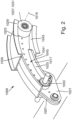
- Fig. 2 shows a connection assembly 1006 of a wing for an aircraft according to the prior art, which is configured to connect a slat to the main wing of an aircraft.
- the connection assembly 1006 may be used in combination with a wing 1 similar to that as described in Fig. 1 , where the wing 1 comprises a main wing 5, a slat 7, and a connection assembly 9 (according to the present disclosure) movably connecting the slat 7 to the main wing 5, such that the slat 7 is movable between a retracted position and at least one extended position.
- connection assembly 1006 comprises a slat track 1017 that extends along a track longitudinal axis 1019 between a front end 1021 and a rear end 1023 and has an intermediate portion 1025 between the front and rear ends 1021, 1023.
- the front end 1021 of the slat track 1017 is fixedly mounted to the slat 1007.
- the rear end 1023 and the intermediate portion 1025 of the slat track 1017 are movably mounted to the main wing 5 by a roller bearing 1027 such that the slat track 1017 is movable along the track longitudinal axis 1019.
- the roller bearing 1027 comprises a guide rail 1029 fixedly mounted to the main wing 5 and a first roller unit 1031 fixedly mounted to the rear end 1023 of the slat track 1017 and engaging the guide rail 1029.
- the roller bearing 1027 comprises a second roller unit 1033 that is fixedly mounted to the main wing 5 and that engages an engagement surface 1035 provided at the intermediate portion 1025 of the slat track 1017.
- the slat track 1017 has a profile comprising an upper flange portion 1039, a lower flange portion 1041 and at least one web portion 1043 connecting upper and lower flange portions 1039, 1041.
- the second roller unit 1033 is arranged in a recess 1045 between upper and lower flange portions 1039, 1041 and engages the engagement surface 1035 provided at the upper flange portion 1039 and at the lower flange portion 1041.
- Figure 3A schematically illustrates a main wing 5 of an aircraft comprising a high lift assembly in the retracted configuration
- Figure 3B shows cross sectional view X-X of Figure 3A
- the high lift assembly comprises a high lift body 7 and a connection assembly 9 which movably connects the high lift body 7 to the main wing 5.
- connection assembly 9 comprises an elongate track 17 that extends along a track longitudinal axis 19 between a first end 21 and a second end 23, and has an intermediate portion 25 located therebetween.
- the high lift body 7 is, in this example, mounted to the first end 21 of the elongate track 17, although may additionally or alternatively be mounted to the intermediate portion 25 thereof.
- the elongate track is also mounted to the main wing 5 by a roller bearing 8.
- the roller bearing 27 permits the track 17 to be moveable along the track longitudinal axis 17 relative to the main wing 5, and therefore also enables movement of the high lift body 7 relative to the main wing 5.
- the roller bearing 27 comprises a plurality of bearing units, in this example three bearing units 34a-c. Each of the bearing units 34a-c is mounted to the main wing 5 and may be mounted by any means possible.
- the bearing units 34a-c each comprise a roller bearing and therefore may be bolted to the main wing 5 so as to enable rotation relative thereto, in this example about a roller axis 20 extending in the axial direction of the roller bearing.
- each of the bearing units comprise a bearing surface 22 for engaging an engagement surface 35 of the elongate track 17.
- the track 17 comprises a first flange 24 and a second flange 26 connected by a web portion 28.
- the first and second flange 24, 26 and the web 28 are oriented in a C-shape to define a recess in which the roller/bearing units are at least partially or wholly located.
- the elongate track 17 may therefore comprise a first and a second internally oriented engagement surface 35a, 35b, which may face each other, and also may extend parallel to one another and optionally parallel to the track longitudinal axis 19.
- the bearing units 34a-c may be dimensioned such that contact is only possible between one of the engagement surfaces 35a, 35b at any one time.
- the bearing units 34a-c of this example are a first end roller unit 34a, an intermediate roller unit 34b and a second end roller unit 34c.
- the intermediate roller unit 34b is positioned between the first end roller unit 34a and the second end roller unit 34c relative to the track longitudinal axis 19 (e.g. positioned in the intermediate portion 25).
- the first end roller unit 34a is, in the retracted position, positioned at (e.g. adjacent) the first end 21 of the elongate track 17 while the second end roller unit 34c is positioned at the second end 23 of the elongate track 17.
- load in the retracted position, load is transferred between the elongate track 17 and the main wing 5 via the first end roller unit 34a and the second end bearing unit 34c. All the load, or substantially all the load, may be transferred between the main wing 5 and the elongate track 17 via the first and second end roller units 34a, 34c in the retracted position, or the principal load (e.g. the majority of the load) may be transferred via the first and second end roller units 34a, 34c.
- the principal load e.g. the majority of the load
- the elongate track 17 additionally comprises a recessed portion 30.
- the recessed portion 30 is present in both the first and second flanges 24, 26 of the elongate track 17.
- the recessed portion 30 extends into the track, and extends in the direction away from the roller axis 20 of the intermediate roller unit 34b. Since the recessed portion 30 extends away from the roller axis 20 of the intermediate roller 34b, it may cause a reduction or elimination in the contact force between the intermediate roller 34b and the engagement surface 35, and in some examples (such as this example) may permit disengagement of the intermediate roller 34b with the engagement surface 35 (e.g. with both engagement surfaces 35a, 35b) such that a clearance gap 52 exists therebetween.
- the loads between the main wing 5 and the elongate track 7 may be transferred through the first and second end bearing units 34a, 34c (in this example, roller units).
- first and second end bearing units 34a, 34c in this example, roller units.
- only two roller units in contact with the engagement surface 35a and/or 35b may transfer force between the main wing 5 and the elongate track 17, thereby avoiding additional forces as a result of the connection assembly 9 being overconstrained in the retracted position.
- the recessed portion 30 comprises a graduated transition to the engagement surface 35 on which it is located, which is illustrated in this way in the form of a ramp.
- the recessed portion may form part of the engagement surface 35 (meaning that it may be possible for the intermediate roller unit 34b to come into contact with part thereof). Additionally or alternatively, the recessed portion may represent a discontinuity in the engagement surface and divide the engagement surface into a first engagement surface extending in a first direction parallel to the track longitudinal axis, and a second engagement surface extending in a second direction parallel to the track longitudinal axis.
- connection assembly 9 and roller bearing 27 shown in Figure 3A are mirrored about the plane 32 extending parallel to the track longitudinal axis 19 and perpendicular to the roller axis 20.
- the connection assembly 9 comprises a second set of flanges 24a, 26a comprising a second set of engagement surfaces 35c, 35d and a second bearing 27a comprising a second set of bearing units 34d-f.
- a description of the mirrored connection assembly will not be provided, although the skilled reader will appreciate that it is as described above in relation to the connection assembly 9.
- the cross-section of the connection assembly 9, and the elongate track 17 of the connection assembly has a substantially pi ( ⁇ ) shape formed by the first C-shaped connected flanges 24, 26 and web portion 28, and equivalent mirrored C-shaped flanges 24a, 26a and web portion being separated by an intermediate space therebetween.
- the cross-sectional shape may be an I-shape, or a double T-shape, while still comprising both the first and mirrored C-shaped flanges 22, 24, 22a, 24a and web portion 28.
- the web portion 28 may be shared between the sets of flanges 22, 24, 22a, 24a.
- Figure 4A illustrates the high lift body 7 of Figure 3A in an extended position.
- Figure 4B illustrates cross section A-A of Figure 4B .
- the elongate track 17 has moved relative to the roller bearing 27.
- neither of the engagement surfaces 35a, 35b are in contact with the second end bearing unit 34c.
- the recessed portion 30 is no longer aligned along the track longitudinal axis 19 with the intermediate roller unit 34b (see also in Figure 4B , there is no gap illustrated between the intermediate bearing 33b on one side thereof, whereas on another side thereof a gap is present to prevent the intermediate bearing 34b from becoming wedged in the track 17), such that the intermediate roller unit 34 is in contact with one of the engagement surfaces 35a, 35b, as is the first end roller unit 34a.
- the first end roller unit 34a and the intermediate roller unit 34b transfer forces between the main wing 5 and the elongate track 17 (e.g. all the forces are transferred by the first end and intermediate roller units 34a, 34b, or the principal force is transferred by the first end and intermediate roller units 34a, 34b).
- forces e.g. all the forces are transferred by the first end and intermediate roller units 34a, 34b, or the principal force is transferred by the first end and intermediate roller units 34a, 34b.
- only two roller/bearing units are in contact with the engagement surface 35a and/or 35b, while the third is disengaged with the elongate track 17. This avoids additional forces as a result of the connection assembly 9 being over constrained.
- Figure 5A and 5B illustrate a further example of a connection assembly 9 in a wing of an aircraft.
- the example of Figures 5A and 5B is similar to that as previously described in relation to Figures 3A and 3B , and 4A and 4B , and for the sake of conciseness similar features will not be described again. Further, similar reference numerals will be used to refer to similar features of Figures 3A to 4B , augmented by 100.
- the second end bearing unit 134c is in the form of a pair of contact pads.
- the contact pads are joined by a web portion 137, such that the contact pads are defined by a single second end bearing unit 134c comprising two contact pads, each having a contact surface 138a,b configurable to contact an engagement surface 135a,b so as to enable sliding contact therebetween.
- the contact surface 138a,b is a crowned surface so as to maximise the contact area and spread out the stress concentrations in the contact area between the contact surfaces 138a, b and the respective engagement surface 135a,b.
- the second end bearing unit 234c comprises a portion that is in the shape of a frustum-cone.
- the central axis 240 of the frustum-cone is aligned with at least a part of the track longitudinal axis 219.
- the second end bearing unit 234c comprises the shape of both a frustum-cone and a cylinder, it may comprise the shape of a full cone, and/or may not comprise a cylindrical shaped section.
- the second end 223 of the elongate track 217 is chamfered so as to increase the distance between the first and second flanges 224, 226.
- the frustum-conical shape of the second end bearing unit 234c, and the chamfered second end 223 assist with aligning the second end bearing unit 234c with the elongate track 217 for example when the track 217 moves into contact with the second end bearing unit 234c into the retracted position.
- Figure 7 illustrates the second end bearing unit 334c as a protrusion (e.g. a cylindrical protrusion) mounted to the main wing (see Figure 3A ), while the elongate track 317 comprises a profile 342 (e.g. a recess) into which the second end bearing unit 334c may mate. Similar to Figure 6A , the profile may be chamfered so as to assist to guide the second end bearing unit 334c into the mating profile.
- a protrusion e.g. a cylindrical protrusion
- the profile 342 e.g. a recess
- Figures 8A and 8B, and 9A and 9B illustrate an example in which the roller bearing comprises a pair of first end roller units 434a, 436a, a pair of intermediate roller units 434b, 436b and a pair of second end roller units 434c, 436c.
- the elongate track 417 comprises a first and second externally oriented engagement surface 435a, 435b.
- the first end roller unit 434a and the second end roller unit 434c are in contact with engagement surface 435a, while the other first end roller unit 436c and the other second end roller unit 436c are in contact with engagement surface 435b.
- Both of the first and second externally oriented engagement surface 435a, 435b comprise a recessed portion, which is recessed so as to extend in a direction away from the roller axis of the intermediate roller unit 434b, 436b associated with the engagement surface 435a,b in which the recessed portion is located.
- the elongate track 417 may comprise a single set of roller/bearing units, which may be elongated so as to stretch between the previously defined first and second sets of engagement surfaces.
- the first and second sets of engagement surfaces may be merged to form just one engagement surface 435a, or may still be separated as two distinct engagement surfaces 435c, 435d. It should be noted that it is also possible for there to be a similar example in which a first and second set of roller/bearing units is possible, rather than single elongated roller/bearing units.
- Figures 9A and 9B illustrate the high lift body in an extended configuration. Similar to as previously described, in the retracted configuration the pair of intermediate bearing units 434b, 436b are disengaged from the respective engagement surface 435a,b, and in an extended configuration, the second end roller units 434c, 436c are disengaged from the respective engagement surface 435a,b.
- Figure 10 illustrates an example in which there are a pair of first end roller bearing units 534a, 536a but just a single intermediate roller bearing unit 534b and a single second end roller bearing unit 534c.
- the elongate track 517 comprises a first and second internally oriented engagement surface 535a, 535b and a first and second externally oriented engagement surface 535e, 535f.
- the pair of first end roller bearing units 534a, 536a engage the first and second externally oriented engagement surfaces 535e, 535f respectively, while the intermediate roller bearing unit 534b is configured to engage the first and second internally orientated engagement surfaces 535a, 535b, as is the second end roller bearing unit 534c. Since the intermediate roller bearing unit 534b is configured to engage the internally oriented engagement surfaces 535e, 535f, the recessed portion is located on the internally oriented engagement surfaces 535e, 535f.
Landscapes
- Engineering & Computer Science (AREA)
- Aviation & Aerospace Engineering (AREA)
- Mechanical Engineering (AREA)
- Bearings For Parts Moving Linearly (AREA)
- Automation & Control Theory (AREA)
Abstract
Described is a wing (3) for an aircraft (1), comprising a main wing (5) and a high lift assembly. The high lift assembly is also described as comprising a high lift body (7), and a connection assembly (9) movably connecting the high lift body (7) to the main wing (5), such that the high lift body (7) is movable between a retracted position (11) and at least one extended position (13, 15). The connection assembly (9) comprises an elongate track (17) that extends along a track longitudinal axis (19) between a first end (21) and a second end (23) and has an intermediate portion (25) between the first and second ends (21, 23). The first end (21) and/or the intermediate portion (25) of the track (17) is mounted to the high lift body (7) and the elongate track (17) is mounted to the main wing (5) by a roller bearing (27) such that the track is movable along the track longitudinal axis (19). The roller bearing (27) comprises a plurality of bearing units (34a-c), each of the bearing units (34a-c) being mounted to the main wing (5) and having a bearing surface (22) for engaging an engagement surface (35) provided on the elongate track (17). In addition, the plurality of bearing units (34a-c) comprises a first end roller unit (34a), an intermediate roller unit (34b) and a second end bearing unit (34c), and the plurality of bearing units (34a-c) are positioned such that, relative to the track longitudinal axis (19), the intermediate roller unit is positioned between the first end roller unit and the second end bearing unit. The elongate track (17) comprises a recessed portion wherein, in the retracted position, the recessed portion is configured to align along the track longitudinal axis (19) with the intermediate roller unit such that a contact force between the intermediate roller unit and the engagement surface (35) of the elongate track (17) is reduced.
Description
- The present invention relates to a wing for an aircraft. Further aspects of the invention relate to a high lift assembly for such a wing, as well as to an aircraft comprising such a wing and/or comprising such a high lift assembly.
- The described wing for an aircraft comprises a main wing and a high lift assembly, the high lift assembly comprising a high lift body and a connection assembly movably connecting the high lift body to the main wing such that the high lift body is movable between a retracted position and at least one extended position (e.g. movable relative to the main wing). The high lift body may be or comprise a leading edge slat or a trailing edge flap of a wing for an aircraft.
- The connection assembly comprises an elongate track that extends along a track longitudinal axis between a first end and a second end and has an intermediate portion between the first and second ends. The elongate track may have a curved or straight form along the track longitudinal axis. At least one, or both, of the first end and the intermediate portion of the elongate track is/are mounted to the high lift body.
- The first end may correspond to a front end of the connection assembly, e.g. the end positioned towards the intended direction of forward motion of the wing during flight of an aircraft. Alternatively, the first end may correspond to a rear end of the connection assembly, e.g. the end positioned away from the intended direction of forward motion of the wing during flight of an aircraft. Where the high lift body is or comprises a leading edge slat, then the first end may correspond to the front end of the connection assembly. Where the high lift body is or comprises a trailing edge flap, then the first end may correspond to the rear end of the connection assembly.
- The first end of the elongate track may be preferably mounted to either a leading edge slat, or to a trailing edge flap by any appropriate means, e.g. by an arrangement of spherical bearings, preferably in a fixed manner with respect to a chord plane. The elongate track may be preferably mounted to the main wing by a roller bearing, as will be described, such that the elongate track and either the leading edge slat or the trailing edge flap are moveable relative to the main wing. The elongate track may take the form of, for example, a C-shape, such that its surface lies opposite the circumferential surface of the roller bearing, wherein the distance between an upper surface and a lower surface of the elongate track is larger than a diameter of a roller bearing, such that the roller bearing may engage only one of the upper surface or the lower surface of the elongate track at any one time. I.e. the distance between the upper and lower surfaces of the elongate track is selected such that a clearance is provided between the roller bearing and either the upper surface or the lower surface of the elongate track, such that the roller bearing cannot engage with the upper and lower surfaces of the elongate track at the same time, thereby becoming wedged therein.
- The elongate track is mounted to the main wing by a roller bearing such that the track is movable along the track longitudinal axis, for example along a predefined path e.g. on the track longitudinal axis, such as between a stowed position which the high lift body is in the retracted position and a deployed position when the high lift body is in one of the at least one extended positions.
- The roller bearing comprises a plurality of bearing units that are mounted to the main wing and have a bearing surface that engages an engagement surface provided on the elongate track.
- Wings for aircraft comprising connection assemblies that movably connect a high lift body to the main wing are known to comprise tracks that are mounted to the main wing via a roller bearing. It is known that keeping such tracks short has the benefit that the front spar of the wing is not penetrated by the track, thus reducing the manufacturing complexity as well as the risk of leaks later in service. The roller bearing of known assemblies experiences a transfer of force from the wing to the elongate track, and thus the roller units of the roller bearing are often positioned as far apart as possible in order to maximise the lever arm therebetween, thus minimizing the transfer of force therethrough. This configuration requires additional rails to support the bearings, which can make the bearing more complex than necessary, while also requiring additional parts, which can add weight to a design.
- Therefore, the object of the present invention is to provide a non-complex, lightweight and low maintenance design of a main wing and associated high lift body and connection assembly.
- The object is achieved in that the plurality of bearing units comprise a first end roller unit, an intermediate roller unit and a second end bearing unit, wherein the plurality of bearing units are positioned such that, relative to the track longitudinal axis, the intermediate roller unit is positioned between the first end roller unit and the second end bearing unit. The roller unit may be mounted to the main wing in any appropriate way, for example may be fixed or fastened to the main wing, for example may be bolted to the main wing.
- Further, the absorbing of the loads (e.g. substantially all the loads or the principal loads or main loads, which may be the majority of the loads) between the main wing and the elongate track may be done by the roller bearing. The elongate track and the roller bearing are configured such that in the retracted position load (in particular the main loads) is transferred (e.g. exclusively transferred) between the elongate track and the main wing (preferably between the elongate track and the roller bearing) via the first end roller unit (e.g. the principal loads are transferred, e.g. exclusively transferred, between the elongate track and the main wing via the first end roller unit) and the second end bearing unit, whereas in the extended position load (in particular the main loads) is transferred between the elongate track and the main wing (preferably between the elongate track and the roller bearing) via the first end roller unit and the intermediate roller unit. This might be achieved by the elongate track and the roller bearing being configured such that in the retracted position (load bearing) contact is present (only) between the elongate track and the first end roller unit as well as between the elongate track and the second end bearing unit, whereas in the extended position (load bearing) contact is present (only) between the elongate track and the first end roller unit as well as between the elongate track and the intermediate roller unit.
- Having an intermediate roller unit permits the elongate track to be fully supported without the need for an additional rail. At the same time, the length of the track can be reduced while loads can be reduced in the retracted position, in particular during cruise flight.
- According to a preferred embodiment, the elongate track further comprises a recessed portion which aligns with the intermediate roller unit in the retracted position such that the contact force between the intermediate roller and the engagement surface of the elongate track is reduced or eliminated, thereby avoiding the roller bearing overconstrained, thereby resulting in additional forces acting between the roller bearing and the elongate track. Further, the lack of an additional rail, plus the configuration of the first and second roller/bearing units may permit a more compact arrangement, thus providing the possibility of easier incorporation of a drive mechanism in the connection assembly, such as a rack-and-pinion or a drive strut combined with a rotary drive. In this case, all or the majority of the load (e.g. the principal loads or main loads) between the wing and the elongate track may be absorbed by the first end roller unit and the second end bearing unit.
- According to a preferred embodiment, when the high lift body is in the retracted position, the intermediate roller unit may be configured to disengage with the engagement surface such that a clearance gap exists between the intermediate roller unit and the engagement surface, and the first end roller unit and the second end bearing unit are configured to engage the engagement surface. When the high lift body is in an extended position, the second end bearing unit may be configured to disengage with the engagement surface and the intermediate roller unit and the first end roller unit is configured to engage with the engagement surface. Allowing the first end roller unit and the second end bearing unit to engage the engagement surface when the high lift body is in the extended position may reduce the contact forces by increasing the length of the lever arm between the bearings.
- The elongate track (e.g. the engagement surface) may be configured to be simultaneously engaged by the first end roller unit and either the intermediate roller unit or the second end bearing unit. As such the elongate track may only simultaneously be engaged by two (e.g. exactly two) roller and/or bearing units (e.g. on one side thereof). Where the connection assembly comprises a second set of engagement surfaces (e.g. a mirrored set of engagement surfaces) as will be described further in more detail in the following paragraphs, the elongate track may be simultaneously engaged by four (e.g. exactly four) roller and/or bearing units, which may correspond to two roller and/or bearing units per set of engagement surfaces. Limiting the number of roller and/or bearing units in engagement with the elongate track may reduce the risk of the elongate track being overconstrained.
- The recessed portion may define a discontinuity in the engagement surface dividing the engagement surface into a first engagement surface extending in a first direction parallel to the track longitudinal axis, and a second engagement surface extending in a second direction parallel to the track longitudinal axis, wherein the first end roller unit is configured to engage the first engagement surface, and the intermediate roller unit and second end bearing are configured to engage the second engagement surface. In providing a divided set of engagement surfaces, the forces acting on the elongate track may be more evenly distributed therealong.
- The recessed portion may comprise a graduated transition to the engagement surface in the form of a ramp. As such, the contact forces may be reduced gradually as a roller and/or bearing unit progresses along the ramp, and may be completely removed e.g. where the roller and/or bearing unit disengages from the engagement surface.
- The recessed portion may be defined by a reduction in thickness of the elongate track, e.g. a part thereof. The elongate track may comprise a first and second flange connected by a web, so as to form a C-shape. The recessed portion may be defined by a reduction in thickness in one or both of the first and second flanges. Where both flanges comprise a reduction in thickness, the thickness reductions may be longitudinally aligned on the track longitudinal axis.
- The second end bearing unit may be a roller unit. The second end bearing unit may comprise a contact pad arrangement and may comprise at least one contact pad surface comprising a crowned surface, thus increasing the contact area therebetween.
- The second end bearing unit may comprise a conical or frustum-conically shaped bearing which, when engaged with the engagement surface, may comprise a longitudinal axis that is parallel with the track longitudinal axis. The second bearing unit may comprise a protrusion mounted to the main wing, and the elongate track may comprise a recess having a profile configured to receive and mate with the second bearing unit. The second end bearing unit may therefore be shaped so as to provide a guiding effect for engagement between the elongate track and the second end bearing unit.
- The elongate track may comprise a first and second internally oriented engagement surface and a first and second externally oriented engagement surface. The first internally oriented engagement surface may face the second internally oriented engagement surface, and the first externally oriented engagement surface may face away from the second externally oriented engagement surface. Each of the first end roller unit, the intermediate roller unit and the second end bearing unit may be configured to engage at least one of the first and second internally oriented engagement surfaces and the first and second externally oriented engagement surfaces.
- The plurality of bearing units may comprise a pair of first end roller units, one of the first end roller units may be configured to engage the first externally oriented engagement surface, and the other of the first end roller units may be configured to engage the second externally oriented engagement surface, and the intermediate roller unit and second end bearing unit may be configured to engage at least one of the first and second internally oriented engagement surfaces.
- The plurality of bearing units may comprise a pair of first end roller units, a pair of intermediate roller units, and a pair of second end bearing units, one of the first end roller units, intermediate roller units and second end bearing units configurable to engage the first externally oriented engagement surface and the other of the first end roller units, intermediate roller units and second end bearing units configurable to engage the second externally oriented engagement surface. Having a pair or several pairs of roller and/or bearing units may allow a much greater load to be taken by the roller/bearing units, and therefore may be useful in situations in which it is knows that loading will be particularly high.
- The connection assembly may comprise a track having a first set of an engagement surface or surfaces and corresponding first end roller unit, intermediate roller unit and second end bearing unit, and also having a second set of an engagement surface or surfaces, corresponding first end roller unit, intermediate roller unit and second end bearing unit. The second set may be a mirror of the first set. Both the first and second set of roller/bearing units may be connected to the main wing.
- A further aspect relates to a high lift assembly for the wing as has been described in any of the preceding paragraphs. The high lift assembly comprises a high lift body, and a connection assembly configured for movably connecting the high lift body to the main wing such that the high lift body is movable between a retracted position and at least one extended position. The connection assembly comprises an elongate track that extends along a track longitudinal axis between a first end and a second end and has an intermediate portion between the first and second ends. The first end and/or the intermediate portion of the track is mounted to the high lift body, and the elongate track is configurable to be mounted to the main wing by a roller bearing such that the track is movable along the track longitudinal axis wherein the roller bearing comprises a plurality of bearing units, each of the bearing units being configurable to be mounted to the main wing and having a bearing surface configurable to engage an engagement surface provided on the elongate track.
- According to this aspect, the plurality of bearing units comprises a first end roller unit, an intermediate roller unit and a second end bearing unit, and the plurality of bearing units are positioned such that, relative to the track longitudinal axis, the intermediate roller unit is positioned between the first end roller unit and the second end bearing unit. The elongate track and the roller bearing are configured such that in the retracted position main loads are transferred between the elongate track and the roller bearing via the first end roller unit and the second end bearing unit, whereas in the extended position main loads are transferred between the elongate track and the roller bearing via the first end roller unit and the intermediate roller unit.
- Another aspect relates to an aircraft comprising a wing according to any of the previous paragraphs, the wing comprising a high lift assembly as has been described.
- It should be noted that, although in the above description the elongate track has been described as being mounted to the main wing by a roller bearing, it may be possible to replace the roller bearing with a slider bearing. In this example, the first end roller unit, intermediate roller unit and second end bearing unit may each be represented by a slider bearing unit, such that sliding contact exists between the engagement surface and the slider bearing units, when contact therebetween is present.
- Figure 1
- is a perspective view of an aircraft, showing a wing of the aircraft;
- Figure 2
- is a connection assembly according to the prior art;
- Figures 3A & 3B
- are views of the disclosed connection assembly in a first configuration;
- Figures 4A & 4B
- are views of the disclosed connection assembly in a second configuration;
- Figures 5A & 5B
- are views of another example of the disclosed connection assembly;
- Figures 6A & 6B
- are views of a further example of the disclosed connection assembly;
- Figure 7
- is a schematic view of an engagement profile of the elongate track for the second end bearing;
- Figures 8A & 8B
- are views of yet another example of the disclosed connection assembly;
- Figures 9A & 9A
- are views of a still further example of the disclosed connection assembly;
- Figure 10
- is a final example of the disclosed connection assembly.
- In
Fig. 1 an aircraft 1 according to an embodiment of the present invention is illustrated. The aircraft 1 comprises awing 3 that is formed according to an embodiment of the present invention. - As shown in
Fig. 1 , theconnection assembly 9 relates to a first connection assembly 91, and thewing 3 comprises a second connection assembly 93 connecting theslat 7 to themain wing 5 in a position spaced apart from the first connection assembly 91 in awing span direction 95, and wherein the second connection assembly 93 is formed as the first connection assembly 91. Additionally illustrated inFig. 1 is awing thickness direction 67. While, inFig. 1 , theconnection assembly 9 is illustrated as connectingslat 7 to themain wing 5, it should also be understood that theconnection assembly 9 may be used to connect a trailing edge flap 2 to thewing 5 of an aircraft. -
Fig. 2 shows aconnection assembly 1006 of a wing for an aircraft according to the prior art, which is configured to connect a slat to the main wing of an aircraft. Theconnection assembly 1006 may be used in combination with a wing 1 similar to that as described inFig. 1 , where the wing 1 comprises amain wing 5, aslat 7, and a connection assembly 9 (according to the present disclosure) movably connecting theslat 7 to themain wing 5, such that theslat 7 is movable between a retracted position and at least one extended position. - According to the prior art, the
connection assembly 1006 comprises aslat track 1017 that extends along a tracklongitudinal axis 1019 between afront end 1021 and arear end 1023 and has anintermediate portion 1025 between the front andrear ends front end 1021 of theslat track 1017 is fixedly mounted to theslat 1007. Therear end 1023 and theintermediate portion 1025 of theslat track 1017 are movably mounted to themain wing 5 by a roller bearing 1027 such that theslat track 1017 is movable along the tracklongitudinal axis 1019. The roller bearing 1027 comprises aguide rail 1029 fixedly mounted to themain wing 5 and a first roller unit 1031 fixedly mounted to therear end 1023 of theslat track 1017 and engaging theguide rail 1029. The roller bearing 1027 comprises asecond roller unit 1033 that is fixedly mounted to themain wing 5 and that engages an engagement surface 1035 provided at theintermediate portion 1025 of theslat track 1017. As shown inFigs. 3-5 , theslat track 1017 has a profile comprising anupper flange portion 1039, alower flange portion 1041 and at least oneweb portion 1043 connecting upper andlower flange portions second roller unit 1033 is arranged in arecess 1045 between upper andlower flange portions upper flange portion 1039 and at thelower flange portion 1041. -
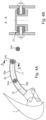
Figure 3A schematically illustrates amain wing 5 of an aircraft comprising a high lift assembly in the retracted configuration, whileFigure 3B shows cross sectional view X-X ofFigure 3A . As illustrated the high lift assembly comprises ahigh lift body 7 and aconnection assembly 9 which movably connects thehigh lift body 7 to themain wing 5. - The
connection assembly 9 comprises anelongate track 17 that extends along a tracklongitudinal axis 19 between afirst end 21 and asecond end 23, and has anintermediate portion 25 located therebetween. Thehigh lift body 7 is, in this example, mounted to thefirst end 21 of theelongate track 17, although may additionally or alternatively be mounted to theintermediate portion 25 thereof. - Illustrated best in
Figure 3B , the elongate track is also mounted to themain wing 5 by a roller bearing 8. Theroller bearing 27 permits thetrack 17 to be moveable along the tracklongitudinal axis 17 relative to themain wing 5, and therefore also enables movement of thehigh lift body 7 relative to themain wing 5. As illustrated inFigure 3A , theroller bearing 27 comprises a plurality of bearing units, in this example three bearingunits 34a-c. Each of the bearingunits 34a-c is mounted to themain wing 5 and may be mounted by any means possible. In this example, the bearingunits 34a-c each comprise a roller bearing and therefore may be bolted to themain wing 5 so as to enable rotation relative thereto, in this example about aroller axis 20 extending in the axial direction of the roller bearing. Here, each of the bearing units comprise a bearingsurface 22 for engaging anengagement surface 35 of theelongate track 17. - Illustrated in
Figure 3B , thetrack 17 comprises afirst flange 24 and asecond flange 26 connected by aweb portion 28. The first andsecond flange web 28 are oriented in a C-shape to define a recess in which the roller/bearing units are at least partially or wholly located. Theelongate track 17 may therefore comprise a first and a second internally orientedengagement surface longitudinal axis 19. In order to avoid jamming of the bearingunits 34a-c, in some examples (such as the example ofFigures 3A and 3B where the bearing units are in the form of roller bearings) thebearing units 34a-c may be dimensioned such that contact is only possible between one of theengagement surfaces - The bearing
units 34a-c of this example are a firstend roller unit 34a, anintermediate roller unit 34b and a secondend roller unit 34c. Here theintermediate roller unit 34b is positioned between the firstend roller unit 34a and the secondend roller unit 34c relative to the track longitudinal axis 19 (e.g. positioned in the intermediate portion 25). The firstend roller unit 34a is, in the retracted position, positioned at (e.g. adjacent) thefirst end 21 of theelongate track 17 while the secondend roller unit 34c is positioned at thesecond end 23 of theelongate track 17. - In this example, in the retracted position, load is transferred between the
elongate track 17 and themain wing 5 via the firstend roller unit 34a and the secondend bearing unit 34c. All the load, or substantially all the load, may be transferred between themain wing 5 and theelongate track 17 via the first and secondend roller units end roller units - The
elongate track 17 additionally comprises a recessedportion 30. The recessedportion 30 is present in both the first andsecond flanges elongate track 17. The recessedportion 30 extends into the track, and extends in the direction away from theroller axis 20 of theintermediate roller unit 34b. Since the recessedportion 30 extends away from theroller axis 20 of theintermediate roller 34b, it may cause a reduction or elimination in the contact force between theintermediate roller 34b and theengagement surface 35, and in some examples (such as this example) may permit disengagement of theintermediate roller 34b with the engagement surface 35 (e.g. with bothengagement surfaces clearance gap 52 exists therebetween. Thus, the loads between themain wing 5 and theelongate track 7 may be transferred through the first and secondend bearing units engagement surface 35a and/or 35b may transfer force between themain wing 5 and theelongate track 17, thereby avoiding additional forces as a result of theconnection assembly 9 being overconstrained in the retracted position. - In this example the recessed
portion 30 comprises a graduated transition to theengagement surface 35 on which it is located, which is illustrated in this way in the form of a ramp. The recessed portion may form part of the engagement surface 35 (meaning that it may be possible for theintermediate roller unit 34b to come into contact with part thereof). Additionally or alternatively, the recessed portion may represent a discontinuity in the engagement surface and divide the engagement surface into a first engagement surface extending in a first direction parallel to the track longitudinal axis, and a second engagement surface extending in a second direction parallel to the track longitudinal axis. - As clearly illustrated in
Figure 3B , theconnection assembly 9 androller bearing 27 shown inFigure 3A are mirrored about theplane 32 extending parallel to the tracklongitudinal axis 19 and perpendicular to theroller axis 20. As such, theconnection assembly 9 comprises a second set offlanges engagement surfaces connection assembly 9. - Illustrated herein, the cross-section of the
connection assembly 9, and theelongate track 17 of the connection assembly has a substantially pi (π) shape formed by the first C-shapedconnected flanges web portion 28, and equivalent mirrored C-shapedflanges flanges web portion 28. In this case, theweb portion 28 may be shared between the sets offlanges -
Figure 4A illustrates thehigh lift body 7 ofFigure 3A in an extended position.Figure 4B illustrates cross section A-A ofFigure 4B . Here, theelongate track 17 has moved relative to theroller bearing 27. In the extended position, neither of theengagement surfaces end bearing unit 34c. Further, the recessedportion 30 is no longer aligned along the tracklongitudinal axis 19 with theintermediate roller unit 34b (see also inFigure 4B , there is no gap illustrated between the intermediate bearing 33b on one side thereof, whereas on another side thereof a gap is present to prevent theintermediate bearing 34b from becoming wedged in the track 17), such that the intermediate roller unit 34 is in contact with one of theengagement surfaces end roller unit 34a. As such, in the illustrated extended position, the firstend roller unit 34a and theintermediate roller unit 34b transfer forces between themain wing 5 and the elongate track 17 (e.g. all the forces are transferred by the first end andintermediate roller units intermediate roller units engagement surface 35a and/or 35b, while the third is disengaged with theelongate track 17. This avoids additional forces as a result of theconnection assembly 9 being over constrained. -
Figure 5A and 5B illustrate a further example of aconnection assembly 9 in a wing of an aircraft. The example ofFigures 5A and 5B is similar to that as previously described in relation toFigures 3A and 3B , and4A and 4B , and for the sake of conciseness similar features will not be described again. Further, similar reference numerals will be used to refer to similar features ofFigures 3A to 4B , augmented by 100. - In contrast to the previous Figures, the second
end bearing unit 134c is in the form of a pair of contact pads. Although twocontact pads 134c are illustrated inFigures 5A and 5B , the contact pads are joined by aweb portion 137, such that the contact pads are defined by a single secondend bearing unit 134c comprising two contact pads, each having acontact surface 138a,b configurable to contact an engagement surface 135a,b so as to enable sliding contact therebetween. In this example, thecontact surface 138a,b is a crowned surface so as to maximise the contact area and spread out the stress concentrations in the contact area between thecontact surfaces 138a, b and the respective engagement surface 135a,b. - A similar idea is illustrated in
Figures 6A and 6B in which the secondend bearing unit 234c comprises a portion that is in the shape of a frustum-cone. In this example thecentral axis 240 of the frustum-cone is aligned with at least a part of the tracklongitudinal axis 219. It should be noted that, although in this example the secondend bearing unit 234c comprises the shape of both a frustum-cone and a cylinder, it may comprise the shape of a full cone, and/or may not comprise a cylindrical shaped section. In addition, thesecond end 223 of theelongate track 217 is chamfered so as to increase the distance between the first and second flanges 224, 226. The frustum-conical shape of the secondend bearing unit 234c, and the chamferedsecond end 223 assist with aligning the secondend bearing unit 234c with theelongate track 217 for example when thetrack 217 moves into contact with the secondend bearing unit 234c into the retracted position. -
Figure 7 illustrates the secondend bearing unit 334c as a protrusion (e.g. a cylindrical protrusion) mounted to the main wing (seeFigure 3A ), while theelongate track 317 comprises a profile 342 (e.g. a recess) into which the secondend bearing unit 334c may mate. Similar toFigure 6A , the profile may be chamfered so as to assist to guide the secondend bearing unit 334c into the mating profile. -
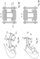
Figures 8A and 8B, and 9A and 9B , illustrate an example in which the roller bearing comprises a pair of firstend roller units intermediate roller units end roller units elongate track 417 comprises a first and second externally orientedengagement surface Figure 8A , the firstend roller unit 434a and the secondend roller unit 434c are in contact withengagement surface 435a, while the other firstend roller unit 436c and the other secondend roller unit 436c are in contact withengagement surface 435b. Both of the first and second externally orientedengagement surface intermediate roller unit engagement surface 435a,b in which the recessed portion is located. It this example, theelongate track 417 may comprise a single set of roller/bearing units, which may be elongated so as to stretch between the previously defined first and second sets of engagement surfaces. As illustrated inFigure 8B , the first and second sets of engagement surfaces may be merged to form just oneengagement surface 435a, or may still be separated as twodistinct engagement surfaces -
Figures 9A and 9B illustrate the high lift body in an extended configuration. Similar to as previously described, in the retracted configuration the pair ofintermediate bearing units respective engagement surface 435a,b, and in an extended configuration, the secondend roller units respective engagement surface 435a,b. -
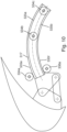
Figure 10 illustrates an example in which there are a pair of first endroller bearing units 534a, 536a but just a single intermediateroller bearing unit 534b and a single second endroller bearing unit 534c. Here theelongate track 517 comprises a first and second internally orientedengagement surface engagement surface roller bearing units 534a, 536a engage the first and second externally orientedengagement surfaces roller bearing unit 534b is configured to engage the first and second internally orientatedengagement surfaces roller bearing unit 534c. Since the intermediateroller bearing unit 534b is configured to engage the internally orientedengagement surfaces engagement surfaces
Claims (15)
- A wing (3) for an aircraft (1), comprisinga main wing (5) anda high lift assembly comprisinga high lift body (7), anda connection assembly (9) movably connecting the high lift body (7) to the main wing (5), such that the high lift body (7) is movable between a retracted position (11) and at least one extended position,wherein the connection assembly (9) comprises an elongate track (17, 217) that extends along a track longitudinal axis (19, 219) between a first end (21) and a second end (23) and has an intermediate portion (25) between the first and second ends (21, 23),wherein the first end (21) and/or the intermediate portion (25) of the track (17, 217) is mounted to the high lift body (7),wherein the elongate track (17,217) is mounted to the main wing (5) by a roller bearing (27) such that the track is movable along the track longitudinal axis (19, 219),wherein the roller bearing (27) comprises a plurality of bearing units (34a-c), each of the bearing units (34a-c) being mounted to the main wing (5) and having a bearing surface (22) for engaging an engagement surface (35) provided on the elongate track (17, 217),characterised in thatthe plurality of bearing units (34a-c) comprises a first end roller unit (34a), an intermediate roller unit (34b) and a second end bearing unit (34c), wherein the plurality of bearing units (34a-c) are positioned such that, relative to the track longitudinal axis (19, 219), the intermediate roller unit (34b) is positioned between the first end roller unit (34a) and the second end bearing unit (34c), andwherein the elongate track and the roller bearing are configured such that in the retracted position main loads are transferred between the elongate track (17, 217) and the roller bearing (27) via the first end roller unit (34a) and the second end bearing unit (34c), whereas in the extended position main loads are transferred between the elongate track (17, 217) and the roller bearing (27) via the first end roller unit (34a) and the intermediate roller unit (34b).
- The wing (3) according to claim 1, wherein in the retracted position, the intermediate roller unit (34b) is configured to disengage with the engagement surface (35) such that a clearance gap (52) exists between the intermediate roller unit (34b) and the engagement surface (35), and the first end roller unit (34a) and the second end bearing unit (34c) are configured to engage the engagement surface (35); and
wherein in an extended position, the second end bearing unit (34c) is configured to disengage with the engagement surface (35) and the intermediate roller unit (34b) and the first end roller unit (34a) is configured to engage with the engagement surface (35). - The wing (3) according to claim 1 or 2, wherein the engagement surface (35) is configured to be simultaneously engaged by the first end roller unit (34a) and either the intermediate roller unit (34) or the second end bearing unit (34c).
- The wing (3) according to any preceding claim, wherein the elongate track (17, 217) comprises a recessed portion (30) wherein, in the retracted position, the recessed portion (30) is configured to align along the track longitudinal axis (19, 219) with the intermediate roller unit (34b) such that a contact force between the intermediate roller unit (34b) and the engagement surface (35) of the elongate track (17, 217) is eliminated or reduced.
- The wing (3) according to claim 4, wherein the recessed portion (30) defines a discontinuity in the engagement surface (35) dividing the engagement surface (35) into a first engagement surface (35a) extending in a first direction parallel to the track longitudinal axis (19, 219), and a second engagement surface (35b) extending in a second direction parallel to the track longitudinal axis (19, 219), wherein the first end roller unit (34a) is configured to engage the first engagement surface (35a), and the intermediate roller unit (34b) and second end bearing (34c) are configured to engage the second engagement surface (35b).
- The wing (3) according to claim 4 or 5, wherein the recessed portion (30) comprises a graduated transition to the engagement surface (35) in the form of a ramp.
- The wing (3) according to any preceding claim, wherein the second end bearing unit (34c) is a roller unit.
- The wing (3) according to any preceding claim, wherein the second end bearing unit (34c) comprises a contact pad arrangement comprising at least one contact pad surface comprising a crowed surface.
- The wing (3) according to any preceding claim, wherein the second end bearing unit (34c) comprises a conical or frustum-conically shaped bearing which, when engaged with the engagement surface (35), comprises a longitudinal axis (240) that is parallel with the track longitudinal axis (19, 219).
- The wing (3) according to any preceding claim, wherein the second bearing unit (34c, 1340, 234c) comprises a protrusion mounted to the main wing (5), and the elongate track (17, 217) comprises a recess having a profile (342) configured to receive and mate with the second end bearing unit (34c, 1340, 234c).
- The wing (3) according to any preceding claim, wherein the elongate track (17, 217) comprises a first and second internally oriented engagement surface (535a, 535b) and a first and second externally oriented engagement surface (535e, 535f), the first internally oriented engagement surface (535a) facing the second internally oriented engagement surface (535b), and the first externally oriented engagement surface (535e) facing away from the second externally oriented engagement surface (535f), and wherein each of the first end roller unit (534a, 536a), the intermediate roller unit (534b, 536b) and the second end bearing unit (534c, 536c) is configured to engage at least one of the first and second internally oriented engagement surfaces (535a, 535b) and the first and second externally oriented engagement surfaces (535e, 535f).
- The wing (3) according to claim 11, wherein the plurality of bearing units (34a-c) comprises a pair of first end roller units (534a, 536a), one of the first end roller units (534a) configured to engage the first externally oriented engagement surface (535e), and the other of the first end roller units (536a) configured to engage the second externally oriented engagement surface (535f), and the intermediate roller unit (534b) and second end bearing unit (534c) being configured to engage at least one of the first and second internally oriented engagement surfaces (535a, 535b).
- The wing (3) according to claim 11, wherein the plurality of bearing units comprises a pair of first end roller units, a pair of intermediate roller units, and a pair of second end bearing units, one of the first end roller units, intermediate roller units and second end bearing units configurable to engage the first externally oriented engagement surface and the other of the first end roller units, intermediate roller units and second end bearing units configurable to engage the second externally oriented engagement surface.
- A high lift assembly for the wing according to any of claims 1 to 13, the high lift assembly comprisinga high lift body (7), anda connection assembly (9) configured for movably connecting the high lift body (7) to the main wing (5), such that the high lift body (7) is movable between a retracted position (11) and at least one extended position (13, 15),wherein the connection assembly (9) comprises an elongate track (17, 217) that extends along a track longitudinal axis (19, 219) between a first end (21) and a second end (23) and has an intermediate portion (25) between the first and second ends (21, 23),wherein the first end (21) and/or the intermediate portion of the track (17, 217) is mounted to the high lift body (7),wherein the elongate track (17, 217) is configurable to be mounted to the main wing by a roller bearing (27) such that the track (17, 217) is movable along the track longitudinal axis (19, 219);wherein the roller bearing (27) comprises a plurality of bearing units (34a-c), each of the bearing units (34a-c) being configurable to be mounted to the main wing (5) and having a bearing surface configurable to engage an engagement surface (35) provided on the elongate track (17, 217);characterized in thatthe plurality of bearing units (34a-c) comprises a first end roller unit, an intermediate roller unit and a second end bearing unit, wherein the plurality of bearing units (34a-c) are positioned such that, relative to the track longitudinal axis (19, 219), the intermediate roller unit is positioned between the first end roller unit and the second end bearing unit; andwherein the elongate track and the roller bearing are configured such that in the retracted position main loads are transferred between the elongate track (17, 217) and the roller bearing (27) via the first end roller unit and the second end bearing unit, whereas in the extended position main loads are transferred between the elongate track (17, 217) and the roller bearing (27) via the first end roller unit and the intermediate roller unit.
- An aircraft (1) comprising a wing (3) according to any of claims 1 to 13, and/or comprising a high lift assembly according to claim 14.
Priority Applications (3)
| Application Number | Priority Date | Filing Date | Title |
|---|---|---|---|
| EP23184990.2A EP4491506A1 (en) | 2023-07-12 | 2023-07-12 | Wing for an aircraft and high lift assembly |
| CN202410340502.2A CN119305719A (en) | 2023-07-12 | 2024-03-25 | Wing for aircraft, high lift component and aircraft |
| US18/769,024 US12589858B2 (en) | 2023-07-12 | 2024-07-10 | Wing for an aircraft and high lift assembly |
Applications Claiming Priority (1)
| Application Number | Priority Date | Filing Date | Title |
|---|---|---|---|
| EP23184990.2A EP4491506A1 (en) | 2023-07-12 | 2023-07-12 | Wing for an aircraft and high lift assembly |
Publications (1)
| Publication Number | Publication Date |
|---|---|
| EP4491506A1 true EP4491506A1 (en) | 2025-01-15 |
Family
ID=87280709
Family Applications (1)
| Application Number | Title | Priority Date | Filing Date |
|---|---|---|---|
| EP23184990.2A Pending EP4491506A1 (en) | 2023-07-12 | 2023-07-12 | Wing for an aircraft and high lift assembly |
Country Status (3)
| Country | Link |
|---|---|
| US (1) | US12589858B2 (en) |
| EP (1) | EP4491506A1 (en) |
| CN (1) | CN119305719A (en) |
Cited By (1)
| Publication number | Priority date | Publication date | Assignee | Title |
|---|---|---|---|---|
| DE102024132505A1 (en) * | 2024-11-07 | 2026-05-07 | Airbus Operations Gmbh | Wings for an airplane |
Families Citing this family (2)
| Publication number | Priority date | Publication date | Assignee | Title |
|---|---|---|---|---|
| USD1072708S1 (en) * | 2023-12-29 | 2025-04-29 | Aerojones Aviation Technology Co., Ltd. | Aircraft |
| WO2025199474A1 (en) * | 2024-03-22 | 2025-09-25 | Odys Aviation, Inc. | Flap drive mechanism |
Citations (2)
| Publication number | Priority date | Publication date | Assignee | Title |
|---|---|---|---|---|
| GB1572004A (en) * | 1978-03-30 | 1980-07-23 | Hawker Siddeley Aviation Ltd | Aircraft wings |
| US20110168849A1 (en) * | 2008-09-03 | 2011-07-14 | Simon John Parker | Slat support assembly |
-
2023
- 2023-07-12 EP EP23184990.2A patent/EP4491506A1/en active Pending
-
2024
- 2024-03-25 CN CN202410340502.2A patent/CN119305719A/en active Pending
- 2024-07-10 US US18/769,024 patent/US12589858B2/en active Active
Patent Citations (2)
| Publication number | Priority date | Publication date | Assignee | Title |
|---|---|---|---|---|
| GB1572004A (en) * | 1978-03-30 | 1980-07-23 | Hawker Siddeley Aviation Ltd | Aircraft wings |
| US20110168849A1 (en) * | 2008-09-03 | 2011-07-14 | Simon John Parker | Slat support assembly |
Cited By (1)
| Publication number | Priority date | Publication date | Assignee | Title |
|---|---|---|---|---|
| DE102024132505A1 (en) * | 2024-11-07 | 2026-05-07 | Airbus Operations Gmbh | Wings for an airplane |
Also Published As
| Publication number | Publication date |
|---|---|
| CN119305719A (en) | 2025-01-14 |
| US12589858B2 (en) | 2026-03-31 |
| US20250019062A1 (en) | 2025-01-16 |
Similar Documents
| Publication | Publication Date | Title |
|---|---|---|
| US12589858B2 (en) | Wing for an aircraft and high lift assembly | |
| US9296473B2 (en) | Slat support assembly | |
| US8181913B2 (en) | Slat support funk plate | |
| CN110546065B (en) | Aircraft wing and connection assembly therein and aircraft with such a wing | |
| US10919616B2 (en) | Guidance assembly for an airfoil leading edge high-lift device carrier track | |
| EP2755889B1 (en) | Landing flap device | |
| EP2316727B1 (en) | High-lift device track | |
| US12037116B2 (en) | High-lift device connection assembly as well as wing and aircraft equipped therewith | |
| US10994830B2 (en) | Flap actuating system for use in an aircraft | |
| EP4741284A1 (en) | Wing for an aircraft | |
| US20190367157A1 (en) | System for driving a flap arrangement between a retracted position and an extended position | |
| US20190127047A1 (en) | Carriage for supporting and guiding a flap and airfoil flap system for use in an aircraft | |
| US20240286731A1 (en) | Wing for an aircraft | |
| US12539959B2 (en) | Wing for an aircraft with a slat assembly | |
| US7004432B2 (en) | Aircraft flap extension mechanism | |
| US11338907B2 (en) | Actuation assemblies for flight control surfaces | |
| CN119305717A (en) | Wing, high lift component, roller unit and aircraft for aircraft | |
| CN114080351A (en) | Connection assembly for an aircraft wing slat | |
| EP4574653A1 (en) | Wing for an aircraft | |
| CN114802713A (en) | Wing of an aircraft, aircraft and connection assembly for a wing | |
| EP4424592A1 (en) | Wing for an aircraft | |
| EP4491507A1 (en) | Wing for an aircraft | |
| US11208194B2 (en) | Assembly for warping of an aerodynamic structure | |
| CN113518745A (en) | Leading edge device of a wing and a wing having such a leading edge device |
Legal Events
| Date | Code | Title | Description |
|---|---|---|---|
| PUAI | Public reference made under article 153(3) epc to a published international application that has entered the european phase |
Free format text: ORIGINAL CODE: 0009012 |
|
| STAA | Information on the status of an ep patent application or granted ep patent |
Free format text: STATUS: THE APPLICATION HAS BEEN PUBLISHED |
|
| AK | Designated contracting states |
Kind code of ref document: A1 Designated state(s): AL AT BE BG CH CY CZ DE DK EE ES FI FR GB GR HR HU IE IS IT LI LT LU LV MC ME MK MT NL NO PL PT RO RS SE SI SK SM TR |
|
| STAA | Information on the status of an ep patent application or granted ep patent |
Free format text: STATUS: REQUEST FOR EXAMINATION WAS MADE |
|
| 17P | Request for examination filed |
Effective date: 20250715 |