EP2755889B1 - Landing flap device - Google Patents
Landing flap device Download PDFInfo
- Publication number
- EP2755889B1 EP2755889B1 EP12750366.2A EP12750366A EP2755889B1 EP 2755889 B1 EP2755889 B1 EP 2755889B1 EP 12750366 A EP12750366 A EP 12750366A EP 2755889 B1 EP2755889 B1 EP 2755889B1
- Authority
- EP
- European Patent Office
- Prior art keywords
- guide
- flap
- lift
- lift flap
- rail
- Prior art date
- Legal status (The legal status is an assumption and is not a legal conclusion. Google has not performed a legal analysis and makes no representation as to the accuracy of the status listed.)
- Not-in-force
Links
Images


Classifications
-
- B—PERFORMING OPERATIONS; TRANSPORTING
- B64—AIRCRAFT; AVIATION; COSMONAUTICS
- B64C—AEROPLANES; HELICOPTERS
- B64C9/00—Adjustable control surfaces or members, e.g. rudders
- B64C9/02—Mounting or supporting thereof
-
- B—PERFORMING OPERATIONS; TRANSPORTING
- B64—AIRCRAFT; AVIATION; COSMONAUTICS
- B64C—AEROPLANES; HELICOPTERS
- B64C9/00—Adjustable control surfaces or members, e.g. rudders
- B64C9/14—Adjustable control surfaces or members, e.g. rudders forming slots
- B64C9/16—Adjustable control surfaces or members, e.g. rudders forming slots at the rear of the wing
-
- B—PERFORMING OPERATIONS; TRANSPORTING
- B64—AIRCRAFT; AVIATION; COSMONAUTICS
- B64C—AEROPLANES; HELICOPTERS
- B64C3/00—Wings
- B64C3/38—Adjustment of complete wings or parts thereof
- B64C3/54—Varying in area
Definitions
- the invention relates to a buoyancy flap arrangement with a buoyancy flap bearing device for guiding and adjusting a buoyancy flap. Furthermore, the invention relates to a wing for an aircraft with such a lift flap assembly. Finally, the invention relates to an aircraft provided with such a wing.
- a drive and guide device for a valve disposed on an aircraft wing flap is known.
- the known drive and guide device has a slide formed by a carriage, on which the flap is movably held, wherein the carriage is movable on a support and guide rail and can be driven by means of an actuator.
- the actuator acts via a lever mechanism with a drive lever and a drive rod.
- a lift flap mechanism for adjusting a lift flap associated with a wing by means of a drive system.
- the known lift flap mechanism is supported on one of a plurality of flap supports secured to the wing and has a steering lever assembly for forming a main connection mechanism and a guide lever for forming a shunt mechanism.
- an airfoil for an aircraft wherein an inner trailing edge flap as the first lift flap and a second trailing edge flap as the second lift flap are arranged in the spanwise side by side, with a suspension between the trailing edge flaps an engine is located.
- the trailing edge flaps are each divided into three sections - a front flap, a center flap and a rear flap - which are not laterally juxtaposed but in succession in the direction of flight and are arranged one behind the other in the retracted state and partly in succession.
- both trailing edge flaps on Auftriebsklappenlagervorraumen which are designed to adjust all three sections.
- a guide device with a curved guide rail is provided for the mutual guidance of the front flap and the middle flap a guide device with a curved guide rail and behind it for mutual guidance of the middle flap and the rear flap.
- the invention has for its object to provide a Auftriebsklappenan Aunt with a buoyancy flap bearing device for guiding and adjustment of lift flaps available that allows improvements in space, manufacturability and / or weight optimizations.
- buoyancy flap assembly Uses of the buoyancy flap assembly are the subject of the dependent claims.
- the invention provides a lift flap assembly according to claim 1, comprising a first lift flap and a laterally disposed second lift flap and a lift flap bearing device disposed between the first and second lift flap.
- the buoyancy flap bearing device is configured to guide and displace the first lift flap and the second lift flap, and is provided with first guide means for guiding the first lift flap and second guide means for guiding the second lift flap, the first and second guide means each having two curved guide rails.
- the first guide device is arranged on a first side of the lift flap bearing device and the second guide device is arranged on a second side opposite to the first side.
- a drive device is provided for the simultaneous adjustment of the first and the second guide device.
- At least one of the guide means comprises a guide slide, which is displaceably guided by means of a first Schienenanlenkung on a first curved guide rail of the guide means and slidably guided by a second Schienenanlenkung on a second curved guide rail.
- the at least one guide carriage has a first flap attachment region with at least one first flap attachment device and a second flap attachment region with at least one second flap attachment device, wherein the first and the second flap attachment device differ from one another are spaced, wherein the first and the second flap mounting portion of the guide carriage are mounted in a direction transverse to a direction guided by the guide device extending direction relatively movable together.
- first and the second guide means are each provided with the guide carriage, wherein the first guide carriage of the first guide means and the second guide carriage of the second guide means are interconnected by means of a transverse connection.
- a base body or base body which can be fastened to a wing which has on a first side the first and the second guide rail of the first guide device and on an opposite second side the first and the second guide rail of the second guide device.
- a carriage arrangement formed by the first guide carriage, the second guide carriage and the cross connection surrounds the base body.
- the drive device arranged in the main body engages the carriage arrangement, in particular at the cross connection.
- At least one of the rail links as a detection element for detecting the associated guide rail has at least one roller which engages at least one roller track of the associated guide rail and / or that at least one of the Schienanlenkungen as a detection element has at least one sliding block, which on a slide of the associated guide rail attacks.
- At least one of the rail linkages with the associated guide rail is in positive engagement to receive lateral lateral forces.
- first rail linkage is slidably supported on a first support surface on the first guide rail
- second rail linkage is slidably supported on a second support surface on the second guide rail, wherein the first support surface is larger than the second support surface and / or the first support surface extends in the direction of displacement over a greater distance than the second support surface.
- the invention provides an aircraft wing provided with such a lift flap assembly.
- the invention provides an aircraft provided with such a wing.
- the lift flaps are preferably landing flaps.
- guiding means for guiding the two flaps are provided in the middle, between two flaps, on both sides at least two curved guide rails for adjustment and preferably a drive for the common adjustment of the lift flaps are provided.
- At least one carriage or guide carriage is provided on which at least one lift flap can be suspended in a swinging manner.
- the guide carriage is preferably subdivided into at least two lift flap attachment regions, which are movable relative to one another, so as to compensate for tilting and / or bending of the lift flaps fastened thereto.
- a base body or base body is provided, on both sides of the guide means are provided with a plurality of curved guide rails and which can be attached to a wing structure, such as a wing.
- a carriage assembly is provided which engages around this body and thus contributes to the stiffening. This makes it unlikely that buoyancy flaps drift from their guides on the body.
- Such a carriage arrangement can be further used to engage a drive for driving together several lift flaps.
- such a carriage arrangement can be used for fastening an aerodynamic fairing for the guide body, which can then be adjusted together with the carriage arrangement and with the buoyancy flaps. This can improve the overall aerodynamics; Slits and gaps can be reduced in the different positions.
- a lateral fixation of the lift flaps is provided for the purpose of receiving transverse loads. This can be achieved, for example, via a positive engagement of a rail linkage which can be connected to the lift flaps to the assigned guide rail.
- a third guide rail e.g. on one of the horizontal sides, e.g. Top or bottom, be provided, which is fixed by a guide member in the longitudinal direction but preferably fixed in the lateral direction is positively detected.
- the Schienenanlenkungen on the at least two curved guide rails is preferably designed differently.
- one of the rail linkages on a first rail is slidably received on the associated guide rail so that it is supported on a larger longitudinal support surface.
- This can be achieved, for example, by a roller arrangement having a plurality of rollers, by an elongate sliding block or by a plurality of sliding blocks which follow one another in the longitudinal direction.
- On the other guide rail is preferably a smaller and lighter rail linkage provided, for example, has only a role or only a smaller sliding block.
- the rail linkages may for example comprise roller and / or sliding blocks, wherein the guide rails are each formed complementary.
- the rail articulations surround a guide rail, as well as embodiments in which the guide rails can detect detection elements - e.g. Roller or sliding blocks - embrace.
- the engagement between the guide rail and associated detection element can be designed for lateral fixation as a form-fitting engagement; for example via corresponding complementary profilings (e.g., projection-rebound formations) of sensing elements and guide rail profiles.
- metal for the guide rails and metal and / or composite materials are provided for the main body.
- a drive device may for example comprise a motor-driven spindle, which is connected via a spindle nut and a connecting rod with an arrangement guided in the guide devices.
- the drive device preferably engages in a transverse connection between two carriages guided laterally by a base body.
- FIG. 1 an airfoil 10 is shown which forms part of an aircraft 12.
- the wing 10 In the area of its trailing edge, the wing 10 has a lift flap arrangement 14 with a plurality of lift flaps 16, 18, 20.
- the lift flaps 16, 18, 20 are, for example, landing flaps, which are extended in the start phase and / or landing phase to increase the buoyancy of the wing 10, and retracted at higher flight speeds in order to optimize the flight operation.
- the lift flap assembly 14 includes a first lift flap 16, a second lift flap 18 and a third lift flap 20 and a first lift flap bearing device 22 between the first lift flap 16 and the second lift flap 18 and a second lift flap storage device between the second lift flap 18 and the third lift flap 20.
- the first lift flap 16 is supported at its end opposite the lift flap bearing device 22 in a lift flap bearing device 26, and the third lift flap 20 is supported in a lift flap bearing device 28 at its end opposite the second lift flap bearing device 24.
- the first lift flap 16 is formed by an inner flap which is mounted at its inner end directed toward the fuselage at an inner lift flap bearing device 26 and at its outer end toward the free end of the wing 10 in the first lift flap bearing device 22.
- the second buoyancy flap 18 is, for example, a central landing flap, which is mounted with its inner end directed towards the fuselage in the first lift flap bearing device 22 and with its outer end directed toward the free end of the wing 10 in the second lift flap bearing device 24.
- the third lift flap 20 is, for example, an outer flap which is mounted with its inner end directed towards the fuselage in the second lift flap bearing device 24 and with its outer end directed toward the free end of the wing 10 in an outer lift flap bearing device 28.
- the lift flap bearing devices 22, 24 and the lift flap bearing devices 26, 28 have guide means 30, 32, which schematically to clarify the function in Fig. 2 are shown in more detail.
- Fig. 2 shows in profile cross-section the trailing edge region of the wing 10 with the wing profile 34 and the second lift flap 18, in a fully retracted position 36 for normal flight - shown in solid lines -, a fully extended position 37 for maximum lift, for example, during the landing approach , and is shown in an intermediate position 38.
- the adjusting movement of the lift flap 18 is guided by the guide devices 30, 32 on the lift flap bearing devices 22, 24 or lift flap bearing devices 26, 28 and driven by a drive in the respective lift flap bearing device 22, 24 explained in more detail later.
- the guide devices 30, 32 have a first curved guide rail 40 and a second curved guide rail 42.
- the first guide rail 40 is, for example, an upper guide rail; and the second guide rail 42 is, for example, a lower guide rail.
- the guide rails 40, 42 have such a curvature and such a course that upon displacement of the guide means 30, 32 mounted Auftriebsklappen 16, 18, 20 each desired Verstelllagen - position of the lift flap 16, 18, 20 in the longitudinal direction of the aircraft 12 and inclination of the Lifting flap 16, 18, 20 with respect to the wing 10 - can be reached.
- buoyancy flap bearing devices 22, 24 based on the exemplary representation of Fig. 3 to 18 explained in more detail.
- the construction of the first lift flap bearing device 22 and the second lift flap bearing device 24 is basically similar and comparable and will therefore be explained in more detail below solely on the basis of the example of the first lift flap bearing device 22.
- the second buoyancy flap bearing device 24 has a very similar construction.
- the buoyancy flap bearing device 22 has a base body 46, a carriage assembly 48 and a drive device 50.
- the main body 46 is connected with its front end portion 52 fixed to the structure of the wing 10, so that the base body 46 is arranged stationary.
- the carriage assembly 48 is slidably guided relative to the main body 46 in the longitudinal direction of the guide means 30, 32.
- lift flaps 16, 18 are fastened with their respective end portions of the carriage assembly 48 (see, eg Fig. 18 ).
- the in the Fig. 4 . Fig. 9 and Fig. 18 Drive device 50 is used to drive the movement of the carriage assembly 48 so as to drive the motor the carriage assembly 48 fastened lift flaps 16, 18 together to adjust.
- first guide means 30 for guiding the first lift flap 16 and on its first side 54 opposing second side 56 - for example, directed to the free end of the wing 10 toward the outer side - provided with a second guide means 32 for guiding the second lift flap 18.
- Both the first guide device 30 and the second guide device 32 each have the first guide rail 40 and the second guide rail 42.
- the first guide means 30 and the second guide means 32 may be mirror images of each other, or may be somewhat different from each other to allow differential movement of the lift flaps 16, 18 mounted on the first lift flap bearing apparatus 22.
- the carriage assembly 48 which without the main body 46 in Fig. 7 is shown in more detail, has a first guide carriage 58, a second guide carriage 60 and a transverse connection 62 which connects the first guide carriage 58 with the second guide carriage 60.
- the first guide carriage 58 is guided in the first guide rail 40 and the second guide rail 42, which are arranged on the first side 54 on the base body 46, so that the first guide means 30 through this first guide rail 40, the second guide rail 42 and the first guide carriage 58 is formed. Accordingly, the second guide device 32 is formed by the arranged on the second side 56 of the guide rails 40, 42 and the guided therein second guide carriage 60.
- Each of the guide carriages 58, 60 has a first flap attachment portion 64 and a second flap attachment portion 66 which are hinged to a degree movable relative to one another.
- first flap attachment portion 64 is formed by a main slider body 68
- second flap attachment portion 66 may be formed by a swing arm 70.
- the first flap attachment region 64 is preferably provided with a first rail linkage 72 for pivoting the guide carriage 58, 60 on the first guide rail 40 and further provided with a second rail linkage 74 for pivoting the guide carriage 58, 60 on the second guide rail 42.
- the rail linkages 72, 74 have detection elements or engagement elements for detecting the respective guide rails 40, 42.
- a first detection element 76 has a roller arrangement 80 with a plurality of rollers, which engage in the channel-like first embodiment of the guide rail 40 in this exemplary embodiment and are thus covered by the first guide rail 40 in the side.
- a second detection element 48 on a single roller 82 which engages in the here also channel-like second guide rail 42 and is detected by the second guide rail 42 on both sides for guidance.
- the first flap attachment region 64 is guided in the guide rails 40, 42.
- the first detection element 46 leads in such a way that larger loads and torques can be introduced into the first guide rail, while the second detection element 78 serves for directional guidance and further support.
- the second flap attachment portion 66 is hinged to the first flap attachment portion 64 so that it can swing out about a vertical axis A relative to the first flap attachment portion 64 toward the left or right side as shown by arrows.
- the swing arm 70 is articulated by two spherical bearings 84 on the main carriage body 78.
- the first flap attachment portion 64 has a first flap fastener 86 for securing a front end portion of the corresponding lift flap 16, 18 to the first flap attachment portion 64.
- the first flap fastener 86 as a flap fastener 86 has a bore for a fastening bolt 85 (see FIG Fig. 14 and 16 ) on.
- the second flap attachment portion 66 includes a second flap fastener 88 that is longitudinally spaced from the first flap fastener 86.
- the second flap fastening device 88 serves for attachment to the area located further back of the corresponding lift flap 16, 18 and can also have a corresponding bore.
- the guide elements 94, 96 are connected by connecting rods 98, 100 to the cross-connection 62.
- the connecting rods 98, 100 are articulated to the guide elements 94, 96 and the transverse connection 62 such that differences in height and inclinations of the transverse connection 62 to the third guide rail 92 can be compensated, but torques about a vertical axis and lateral loads are supported.
- the cross-link 62 is formed as a rod member or elongated plate member and connects the two main carriage body 68 or more generally the first flap attachment portion 64 of the first guide carriage 58 and the first flap attachment portion 64 of the second guide carriage 60 together.
- the carriage arrangement 48 is thus designed such that that it encompasses the base body 46. As a result, even with the use of lightweight materials stiffening can be achieved.
- Fig. 8 the guide of the respective guide carriage 58 in the first guide rail 40 and the second guide rail 42 by means of the detection elements 76, 78 is shown.
- the drive device 50 further engages the cross link 62 to drive the movement of the carriage assembly 48 longitudinally along the guide rails 40, 42.
- this has the drive means 50 an electric motor 102 with connected gear 104 and a rotationally driven by the gear 104 spindle 106.
- a spindle nut 108 is movable in the direction of the axis of rotation of the spindle 106 by rotation thereof.
- This spindle nut 108 is connected to the transverse connection 62 by means of a connecting strut 110.
- the entire drive device 50 is received and secured within the body 46.
- the guide rails 40, 42 are preferably formed of metal, for example aluminum.
- the carriage assembly 48 is preferably formed of metal, in particular of aluminum.
- the cross-connection 62 which can also be referred to as a spindle arm, can be made of extruded aluminum in order to enable a high degree of bending capability.
- the main carriage body 68 may be made of milled aluminum to allow high load resistance and load transfer.
- the swing arm 70 may be made of forged aluminum to accommodate movements within the lift flap assembly 14.
- Fig. 10 shows a partial sectional view through the rear edge portion of the wing 10 and the Auftriebsklappenan elbow 14, wherein the section is selected so that the second guide means 32 with the first guide rail 40, the second guide rail 42 and guided therein Schienenanlenkungen 72, 74 can be seen.
- a movable cowling 110 of an aerodynamic cowling 112 may be secured to the carriage assembly 48.
- the complete aerodynamic fairing 112 is in Fig. 12 shown again without the other parts of the buoyancy flap bearing device 22.
- the aerodynamic fairing 112 has the movable cowling 110 and a stationary cowling 114 which is fixedly attached to the body 46.
- the two trim parts 110, 114 have overlapping areas 116, so that gaps can be minimized.
- Fig. 13 shows a further section through the rear portion of the wing 10 and the lift flap assembly 14, wherein the entire first lift flap bearing device 22 with base body 46 and carriage assembly 48 including the second guide carriage 60 is shown.
- Fig. 14 can be at this guide carriage 60, the second buoyancy flap 18 hinged, which is shown here in profile to show the internal structure of the lift doors 16, 18, 20.
- the lift flaps 16, 18, 20 are preferably made of composite materials such as e.g. fiber-reinforced plastics or made of metal or in a hybrid construction in which composite materials and metals are used in combination. Also other components of the lift flap bearing apparatus, such as e.g.
- At least one of the guide carriages - in particular the second guide carriage 60 -, at least one of the flap attachment areas - in particular the second flap attachment area 66, the swing arm 70, at least one of the trim parts - in particular the movable trim part 110 and / or the stationary trim part 114 - and / or Cladding 112 may be made of composite materials, such as fiber reinforced plastics or of metal, or in a hybrid construction, wherein composite material (s) and metal (s) are used in combination, to be produced.
- a main body of the lift flap 16, 18, 20 is provided with a plurality of transverse bars 118 for stiffening.
- the Auftriebsflappen 16, 18, 20 is carried out in the Auftriebsklappenan Aunt 14 shown here alone on the lateral end portions and on the side end surfaces. Therefore, no articulation points on wide surfaces of the lift doors 16, 18, 20 are necessary, so that the structure can be simplified.
- Fig. 15 1 shows an embodiment of the lift flap bearing apparatus 22 where only a lower slide is connected to the lift flaps 16, 18, 20, whereas the lift flaps 16, 18, 20 otherwise engage directly with the guide rails 40, 42.
- this embodiment is also possible in principle, but has the in Fig. 15 indicated disadvantage that bending of the wing 10 lead to a load in the guide means 30, 32, so that there is a higher wear and the risk of misalignment.
- Fig. 16 shows for comparison a schematic diagram of the basis of Fig. 3 to 14 explained preferred embodiment with the encompassing carriage assembly 48, which provides a stiffening due to the gripping and the lateral fixation, wherein the connection of the lift flaps 16, 18, 20 via the compensating guide carriage 58, 60 can be done.
- Fig. 17 and Fig. 18 show once again the function of these balancing guide carriages 58, 60 and the overall construction of the lift flap bearing apparatus 22.
- the structure of the lift flap bearing devices 26, 28, which support the inner end of the inner lift flap 16 and the outer end of the outer lift flap 20, is not shown in detail, it follows from the detailed construction of the lift flap bearing device 22 by omitting one of the guide means and the drive means 50.
- the lift flap bearing devices 26, 28 are simply formed by one of the guide means 30, 32 with the correspondingly curved guide rails 40, 42, to which either directly, as in FIG Fig. 15 indicated or by intermediate storage of the guide carriage 58, 60, the buoyancy flap 18, 20 is guided.
- the lift flap assembly 14 shown here with only two actuators for the adjustment of three lift flaps 16, 18, 20 comes from.
- Fig. 19 and 20 show comparisons of known wings 10a (as used in the Airbus aircraft A320) with an inventive design of the wing 10, wherein the Fig. 19a and the Fig. 20a the known wing 10 a and the Fig. 19b and the Fig. 20b show the wing 10 according to the embodiment of the invention.
- the lift flap arrangement 14a of the known wing 10a has two lift flaps 16a, 18a, which are each adjustable and driven from a central region of the lift flaps 16a, 18a become; and with a construction as they are basically in the EP 0 503 158 A1 or the WO 03/008266 A1 is explained.
- lift flap assembly 14 having only two lift flaps, for example the first lift flap 16 and the second lift flap 18 and only one lift flap bearing device 22 therebetween.
- Embodiments with more than three lift flaps are also conceivable, wherein preferably one buoyancy flap bearing device 22, 24 is provided for jointly storing and driving between each two adjacent lift flaps.
- detection elements 76, 78 are used as detection elements 76, 78 for detecting the guide rails 40, 42 roller assemblies 80 and rollers 82.
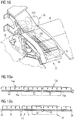
- the Fig. 21 to 30 On the other hand, further possible embodiments of the detection elements 76, 78 and profiles of the guide rails 40, 42 adapted thereto are shown. In this case, sliding blocks 120 are used as detection elements 76, 78.
- FIGS. 21 . 22 and 24 show an embodiment in which a guide rail 122 is detected on the outside by the associated Schienenanlenkung 72, 74 with two sliding blocks 120.
- FIGS. 23 and 25 On the other hand, embodiments in which C-shaped guide rail profiles or U-shaped guide rail profiles 124 include a sliding block 120 guided therein.
- the Fig. 21 . 22 and 23 show a positive detection between sliding block 120 and guide rail 122, so that at the same time a lateral fixation within the guide device 30, 32 can be reached.
- the FIGS. 24 and 25 show embodiments with which a purely frictional engagement between guide rail 122 and sliding block 120 has been realized so that lateral movements can be compensated.
- the Fig. 21 shows in three individual representations Fig. 21a, Fig. 21b and Fig. 21c as the corresponding embodiments of FIGS. 22 to 25 can be realized in the Auftriebsklappenlagervorraum 22.
- the corresponding guide rails 40, 42 are replaced by the guide rails 122 ( Fig. 21b ) and the Schienenanlenkungen 72, 74 are replaced by the detection between Gleitstein 120 and guide rail 122 ( Fig. 21c ).
- Fig. 26 shows an alternative guide rail assembly 126, wherein the first guide rail 40 and the second guide rail 42 each have the encompassing guide rail profile 124.
- FIGS. 22 to 25 Either a positive detection or a frictional detection (without positive locking) is provided.
- Fig. 27 on the other hand shows an embodiment of the Schienenanlenkung 72, 74, in which one side of the sliding block 120 is designed for positive detection and another side for frictional engagement.
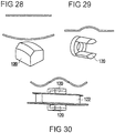
- Fig. 28 shows, for example in a schematic representation and in perspective view of a design of the sliding block 120 with one side flat side and a rounded side.
- Fig. 29 shows an embodiment of the sliding block 120 (designed as encompassing sliding block), wherein the flat areas combined with convex areas.
- Fig. 30 shows an embodiment of the sliding block 120 with a viewed in the longitudinal direction of the sliding block 120 initially convex, then concave and finally convex configuration.
- the last-mentioned embodiment of the sliding block 120 is the most preferred, since this makes it possible to support the sliding block 120 against rotation and / or support on a larger support area, and yet a relatively small contact surface is used.
Description
Die Erfindung betrifft eine Auftriebsklappenanordnung mit einer Auftriebsklappenlagervorrichtung zur Führung und Verstellung einer Auftriebsklappe. Weiter betrifft die Erfindung einen Tragflügel für ein Flugzeug mit einer solchen Auftriebsklappenanordnung. Schließlich betrifft die Erfindung ein mit einem solchen Tragflügel versehenes Flugzeug.The invention relates to a buoyancy flap arrangement with a buoyancy flap bearing device for guiding and adjusting a buoyancy flap. Furthermore, the invention relates to a wing for an aircraft with such a lift flap assembly. Finally, the invention relates to an aircraft provided with such a wing.
Aus der
Aus der
Aus der
Eine weitere vergleichbare Klappenlagervorrichtung zur Führung unterschiedlicher hintereinander angeordneter Sektionen einer Hinterkantenklappe ist aus der
Aus der
Der Erfindung liegt die Aufgabe zugrunde, eine Auftriebsklappenanordnung mit einer Auftriebsklappenlagervorrichtung zur Führung und Verstellung von Auftriebsklappen zur Verfügung zu stellen, die Verbesserungen hinsichtlich Bauraum, Herstellbarkeit und/oder Gewichtsoptimierungen ermöglicht.The invention has for its object to provide a Auftriebsklappenanordnung with a buoyancy flap bearing device for guiding and adjustment of lift flaps available that allows improvements in space, manufacturability and / or weight optimizations.
Diese Aufgabe wird mit einer Auftriebsklappenanordnung nach Anspruch 1 gelöst. Vorteilhafte Ausgestaltungen sind Gegenstand der Unteransprüche. VorteilhafteThis object is achieved with a lift flap arrangement according to
Verwendungen der Auftriebsklappenanordnung sind Gegenstand der Nebenansprüche.Uses of the buoyancy flap assembly are the subject of the dependent claims.
Die Erfindung schafft eine eine Auftriebsklappenanordnung nach Anspruch 1, umfassend eine erste Auftriebsklappe und eine seitlich dazu angeordnete zweite Auftriebsklappe sowie eine zwischen der ersten und der zweiten Auftriebsklappe angeordnete Auftriebsklappenlagervorrichtung. Die Auftriebsklappenlagervorrichtung ist zur Führung und Verstellung der ersten Auftriebsklappe und der zweiten Auftriebsklappe ausgebildet und mit einer ersten Führungseinrichtung zum Führen der ersten Auftriebsklappe und einer zweiten Führungseinrichtung zum Führen der zweiten Auftriebsklappe versehen, wobei die erste und die zweite Führungseinrichtung jeweils zwei gekrümmte Führungsschienen aufweisen.The invention provides a lift flap assembly according to
Dabei ist vorgesehen, dass die erste Führungseinrichtung auf einer ersten Seite der Auftriebsklappenlagervorrichtung angeordnet ist und die zweite Führungseinrichtung auf einer der ersten Seite entgegengerichteten zweiten Seite angeordnet ist.In this case, it is provided that the first guide device is arranged on a first side of the lift flap bearing device and the second guide device is arranged on a second side opposite to the first side.
Besonders bevorzugt ist, dass eine Antriebseinrichtung zum gleichzeitigen Verstellen der ersten und der zweiten Führungseinrichtung vorgesehen ist.It is particularly preferred that a drive device is provided for the simultaneous adjustment of the first and the second guide device.
Vorzugsweise ist vorgesehen, dass wenigstens eine der Führungseinrichtungen einen Führungsschlitten aufweist, der mittels einer ersten Schienenanlenkung verschiebbar an einer ersten gekrümmten Führungsschiene der Führungseinrichtung verschiebbar geführt ist und mittels einer zweiten Schienenanlenkung verschiebbar an einer zweiten gekrümmten Führungsschiene verschiebbar geführt ist.It is preferably provided that at least one of the guide means comprises a guide slide, which is displaceably guided by means of a first Schienenanlenkung on a first curved guide rail of the guide means and slidably guided by a second Schienenanlenkung on a second curved guide rail.
Gemäß einer Ausgestaltung der Erfindung ist vorgesehen, dass der wenigstens eine Führungsschlitten einen ersten Klappenbefestigungsbereich mit wenigstens einer ersten Klappenbefestigungseinrichtung und eine zweiten Klappenbefestigungsbereich mit wenigstens einer zweiten Klappenbefestigungseinrichtung aufweist, wobei die erste und die zweite Klappenbefestigungseinrichtung voneinander beabstandet sind, wobei der erste und der zweite Klappenbefestigungsbereich des Führungsschlittens in quer zu einer durch die Führungseinrichtung geführten Verstellrichtung verlaufenden Richtung relativ beweglich zueinander aneinander befestigt sind.According to one embodiment of the invention, it is provided that the at least one guide carriage has a first flap attachment region with at least one first flap attachment device and a second flap attachment region with at least one second flap attachment device, wherein the first and the second flap attachment device differ from one another are spaced, wherein the first and the second flap mounting portion of the guide carriage are mounted in a direction transverse to a direction guided by the guide device extending direction relatively movable together.
Es ist bevorzugt, dass die erste und die zweite Führungseinrichtung jeweils mit dem Führungsschlitten versehen sind, wobei der erste Führungsschlitten der ersten Führungseinrichtung und der zweite Führungsschlitten der zweiten Führungseinrichtung mittels einer Querverbindung miteinander verbunden sind.It is preferred that the first and the second guide means are each provided with the guide carriage, wherein the first guide carriage of the first guide means and the second guide carriage of the second guide means are interconnected by means of a transverse connection.
Besonders bevorzugt ist, dass ein an einem Tragflügel befestigbarer Grundkörper oder Grundkörper vorgesehen ist, der auf einer ersten Seite die erste und die zweite Führungsschiene der ersten Führungseinrichtung und auf einer entgegengerichteten zweiten Seite die erste und die zweite Führungsschiene der zweiten Führungseinrichtung aufweist.It is particularly preferred that a base body or base body which can be fastened to a wing is provided which has on a first side the first and the second guide rail of the first guide device and on an opposite second side the first and the second guide rail of the second guide device.
Vorzugsweise ist vorgesehen, dass eine durch den ersten Führungsschlitten, den zweiten Führungsschlitten und die Querverbindung gebildete Schlittenanordnung den Grundkörper umgreift.It is preferably provided that a carriage arrangement formed by the first guide carriage, the second guide carriage and the cross connection surrounds the base body.
Bei einer vorteilhaften Ausgestaltung ist vorgesehen, dass die in dem Grundkörper angeordnete Antriebseinrichtung an der Schlittenanordnung, insbesondere an der Querverbindung, angreift.In an advantageous embodiment, it is provided that the drive device arranged in the main body engages the carriage arrangement, in particular at the cross connection.
Es ist bevorzugt, dass wenigstens eine der Schienenanlenkungen als Erfassungselement zum Erfassen der zugeordneten Führungsschiene wenigstens eine Rolle aufweist, die an wenigstens einer Rollenbahn der zugeordneten Führungsschiene angreift und/oder dass wenigstens eine der Schienanlenkungen als Erfassungselement wenigstens einen Gleitstein aufweist, der an einer Gleitbahn der zugeordneten Führungsschiene angreift.It is preferred that at least one of the rail links as a detection element for detecting the associated guide rail has at least one roller which engages at least one roller track of the associated guide rail and / or that at least one of the Schienanlenkungen as a detection element has at least one sliding block, which on a slide of the associated guide rail attacks.
Besonders bevorzugt ist, dass wenigstens eine der Schienenanlenkungen mit der zugeordneten Führungsschiene in formschlüssigen Eingriff ist, um seitliche Querkräfte aufzunehmen.It is particularly preferred that at least one of the rail linkages with the associated guide rail is in positive engagement to receive lateral lateral forces.
Vorzugsweise ist vorgesehen, dass die erste Schienenanlenkung verschiebbar auf einer ersten Stützfläche an der ersten Führungsschiene abgestützt ist, während die zweite Schienenanlenkung verschiebbar auf einer zweiten Stützfläche an der zweiten Führungsschiene abgestützt ist, wobei die erste Stützfläche größer als die zweite Stützfläche ist und/oder wobei sich die erste Stützfläche in Verschieberichtung über eine größere Strecke als die zweite Stützläche erstreckt.It is preferably provided that the first rail linkage is slidably supported on a first support surface on the first guide rail, while the second rail linkage is slidably supported on a second support surface on the second guide rail, wherein the first support surface is larger than the second support surface and / or the first support surface extends in the direction of displacement over a greater distance than the second support surface.
Gemäß eines weiteren Aspekts schafft die Erfindung einen mit einer solchen Auftriebsklappenanordnung versehenen Tragflügel für ein Flugzeug.In another aspect, the invention provides an aircraft wing provided with such a lift flap assembly.
Gemäß eines weiteren Aspekts schafft die Erfindung ein mit einem solchen Tragflügel versehenes Flugzeug.In another aspect, the invention provides an aircraft provided with such a wing.
Die Auftriebsklappen sind vorzugsweise Landeklappen.The lift flaps are preferably landing flaps.
In einer besonders bevorzugten Ausgestaltung der Erfindung sind in der Mitte, zwischen zwei Landeklappen, Führungseinrichtungen zum Führen der beiden Landeklappen vorgesehen, wobei beidseitig wenigstens zwei gekrümmte Führungsschienen zur Verstellung und vorzugsweise ein Antrieb zur gemeinsamen Verstellung der Auftriebsklappen vorgesehen sind.In a particularly preferred embodiment of the invention, guiding means for guiding the two flaps are provided in the middle, between two flaps, on both sides at least two curved guide rails for adjustment and preferably a drive for the common adjustment of the lift flaps are provided.
Vorteile der Erfindung oder vorteilhafter Ausgestaltungen davon sind insbesondere:
- Es ist nur ein geringerer Bauraum für die Lagervorrichtung und die Verstelleinrichtung zum Lagern und Verstellen der Auftriebsklappen nötig;
- Die Auftriebsklappenlagervorrichtung ist von der Struktur her leichter als bisher bekannte Auftriebsklappenlagerungen und -verstellungen;
- Die Auftriebsklappenanordnung lässt sich leichter herstellen; insbesondere wird eine einfachere Montage ermöglicht und/oder lässt sich Montagezeit einsparen;
- Aufgrund des kompakten Aufbaus lässt sich eine kleinere Kopffläche und damit ein geringerer Luftwiderstand und so eine bessere Aerodynamik erreichen;
- Eine geforderte Landeklappenposition im ausgefahrenen Zustand mit bester Aerodynamik lässt sich leichter erfüllen als mit bisher bekannten Lager- und/oder Verstelleinrichtungen;
- Es lässt sich eine optimale Lagerung für sogenannte Vielholmer-Landeklappen und/oder Verbundwerkstoff-Landeklappen mit Querholmversteifungen erreichen.
- There is only a smaller space for the storage device and the adjustment for storing and adjusting the lift flaps necessary;
- The lift flap bearing apparatus is structurally lighter than previously known lift flap bearings and adjustments;
- The buoyancy flap assembly is easier to manufacture; in particular, a simpler installation is made possible and / or installation time can be saved;
- Due to the compact design, a smaller head surface and thus a lower air resistance and thus achieve better aerodynamics;
- A required flap position in the extended state with the best aerodynamics can be easier to meet than with previously known storage and / or adjustment;
- It can be an optimal storage for so-called Vielholmer landing flaps and / or composite flaps with Querholmversteifungen reach.
Gemäß einer bevorzugten Ausgestaltung ist wenigstens ein Wagen oder Führungsschlitten vorgesehen, an dem sich wenigstens eine Auftriebsklappe schwingend aufhängen lässt. Vorzugsweise ist der Führungsschlitten hierzu in wenigstens zwei Auftriebsklappenbefestigungsbereiche unterteilt, die beweglich zueinander sind, um so Verkantungen und/oder Verbiegungen der daran befestigten Auftriebsklappen auszugleichen.According to a preferred embodiment, at least one carriage or guide carriage is provided on which at least one lift flap can be suspended in a swinging manner. For this purpose, the guide carriage is preferably subdivided into at least two lift flap attachment regions, which are movable relative to one another, so as to compensate for tilting and / or bending of the lift flaps fastened thereto.
Vorzugsweise ist ein Grundkörper oder Basiskörper vorgesehen, an dem beidseitig Führungseinrichtungen mit mehreren gekrümmten Führungsschienen vorhanden sind und der an einer Flügelstruktur, beispielsweise einem Tragflügel, befestigt werden kann.Preferably, a base body or base body is provided, on both sides of the guide means are provided with a plurality of curved guide rails and which can be attached to a wing structure, such as a wing.
Vorzugsweise ist eine Schlittenanordnung vorgesehen, die diesen Grundkörper umgreift und somit zur Versteifung beiträgt. Dadurch ist es wenig wahrscheinlich, dass Auftriebsklappen aus ihren Führungen am Grundkörper driften.Preferably, a carriage assembly is provided which engages around this body and thus contributes to the stiffening. This makes it unlikely that buoyancy flaps drift from their guides on the body.
Eine solche Schlittenanordnung lässt sich weiter zum Angreifen eines Antriebes zum gemeinsamen Antreiben mehrere Auftriebsklappen nutzen.Such a carriage arrangement can be further used to engage a drive for driving together several lift flaps.
Weiter lässt sich eine solche Schlittenanordnung zur Befestigung einer aerodynamischen Verkleidung für den Führungskörper nutzen, die sich dann mit der Schlittenanordnung und mit den Auftriebsklappen gemeinsam verstellen lässt. Dadurch lässt sich insgesamt die Aerodynamik verbessern; Schlitze und Spalte lassen sich in den unterschiedlichen Stellungen verringern.Furthermore, such a carriage arrangement can be used for fastening an aerodynamic fairing for the guide body, which can then be adjusted together with the carriage arrangement and with the buoyancy flaps. This can improve the overall aerodynamics; Slits and gaps can be reduced in the different positions.
Vorzugsweise ist eine seitliche Fixierung der Auftriebsklappen zwecks Aufnahme von Querlasten vorgesehen. Dies lässt sich beispielsweise über einen formschlüssigen Angriff einer mit den Auftriebsklappen verbindbaren Schienenanlenkung an der zugeordneten Führungsschiene erreichen.Preferably, a lateral fixation of the lift flaps is provided for the purpose of receiving transverse loads. This can be achieved, for example, via a positive engagement of a rail linkage which can be connected to the lift flaps to the assigned guide rail.
Alternativ oder zusätzlich kann zur seitlichen Fixierung eine dritte Führungsschiene, z.B. an einer der horizontalen Seiten, z.B. Oberseite oder Unterseite, vorgesehen sein, die durch ein Führungselement in Längsrichtung verschiebbar aber in seitlicher Richtung fixiert vorzugsweise formschlüssig erfasst wird.Alternatively or additionally, for lateral fixation, a third guide rail, e.g. on one of the horizontal sides, e.g. Top or bottom, be provided, which is fixed by a guide member in the longitudinal direction but preferably fixed in the lateral direction is positively detected.
Die Schienenanlenkungen an den wenigstens zwei gekrümmten Führungsschienen ist vorzugsweise unterschiedlich ausgestaltet. Beispielsweise ist eine der Schienenanlenkungen an einer ersten Schiene verschiebbar an der zugeordneten Führungsschiene derart aufgenommen, dass sie sich auf einer größeren längsgerichteten Stützfläche abstützt. Dies kann z.B. durch eine Rollenanordnung mit mehreren Rollen, durch einen länglichen Gleitstein oder durch in Längsrichtung aufeinanderfolgende mehrere Gleitsteine erreicht werden. An der weiteren Führungsschiene ist vorzugsweise eine kleinere und leichtgewichtigere Schienenanlenkung vorgesehen, die z.B. nur eine Rolle oder nur einen kleinere Gleitstein aufweist.The Schienenanlenkungen on the at least two curved guide rails is preferably designed differently. For example, one of the rail linkages on a first rail is slidably received on the associated guide rail so that it is supported on a larger longitudinal support surface. This can be achieved, for example, by a roller arrangement having a plurality of rollers, by an elongate sliding block or by a plurality of sliding blocks which follow one another in the longitudinal direction. On the other guide rail is preferably a smaller and lighter rail linkage provided, for example, has only a role or only a smaller sliding block.
Die Schienenanlenkungen können beispielsweise Rollen- und/oder Gleitsteine aufweisen, wobei die Führungsschienen jeweils komplementär ausgebildet sind. Es sind sowohl Ausführungen denkbar, bei denen die Schienenanlenkungen eine Führungsschiene umgreifen, als auch Ausführungen denkbar, bei denen die Führungsschienen Erfassungselemente - z.B. Rollen- oder Gleitsteine - umgreifen. Der Eingriff zwischen Führungsschiene und zugeordnetem Erfassungselement kann zur seitlichen Fixierung als formschlüssig Eingriff ausgebildet sein; beispielsweise über entsprechende Komplementärprofilierungen (z.B. Vorsprung-Rücksprungausbildungen) von Erfassungselementen und Führungsschienenprofilen.The rail linkages may for example comprise roller and / or sliding blocks, wherein the guide rails are each formed complementary. Embodiments are conceivable in which the rail articulations surround a guide rail, as well as embodiments in which the guide rails can detect detection elements - e.g. Roller or sliding blocks - embrace. The engagement between the guide rail and associated detection element can be designed for lateral fixation as a form-fitting engagement; for example via corresponding complementary profilings (e.g., projection-rebound formations) of sensing elements and guide rail profiles.
Als Materialien sind vorzugsweise Metall für die Führungsschienen und Metall und/oder Verbundwerkstoffe für den Grundkörper vorgesehen.As materials preferably metal for the guide rails and metal and / or composite materials are provided for the main body.
Eine Antriebseinrichtung kann beispielsweise eine motorgetriebene Spindel aufweisen, die über eine Spindelnuss und eine Verbindungsstange mit einer in den Führungseinrichtungen geführten Anordnung verbunden ist. Vorzugsweise greift die Antriebseinrichtung an einer Querverbindung zwischen zwei seitlich von einem Grundkörper geführten Schlitten an.A drive device may for example comprise a motor-driven spindle, which is connected via a spindle nut and a connecting rod with an arrangement guided in the guide devices. The drive device preferably engages in a transverse connection between two carriages guided laterally by a base body.
Ausführungsbeispiele der Erfindung werden im Folgenden anhand der beigefügten Zeichnungen näher erläutert. Dabei zeigen:
- Fig. 1
- eine schematische perspektivische Darstellung eines Tragflügels mit einer Auftriebsklappenanordnung mit mehreren Auftriebsklappen sowie mit mehreren Auftriebsklappenlagervorrichtungen;
- Fig. 2
- eine schematische Querschnittsdarstellung durch den Tragflügel von
Fig. 1 zur Verdeutlichung der durch die Auftriebsklappenlagervorrichtung geführten Verstellbewegung der Auftriebsklappen; - Fig. 3
- eine erste perspektivische Ansicht einer Auftriebsklappenlagervorrichtung;
- Fig. 4
- eine zweite perspektivische Ansicht einer Auftriebsklappenlagervorrichtung;
- Fig. 5
- eine schematische perspektivische Darstellung eines Grundkörpers der Auftriebsklappenlagervorrichtung;
- Fig. 6
- eine weitere perspektivische Darstellung des Grundkörpers der Auftriebsklappenlagervorrichtung;
- Fig. 7
- eine schematische perspektivische Ansicht einer Schlittenanordnung der Auftriebsklappenlagervorrichtung der
Fig. 3 und 4 ; - Fig. 8
- eine perspektivische schematische Darstellung eines Teils der Schlittenanordnung von
Fig. 7 in Eingriff mit einer Führungseinrichtung des Grundkörpers vonFig. 5 ; - Fig. 9
- eine schematische perspektivische Schnittdarstellung durch den hinteren Bereich des Tragflügels von
Fig. 1 auf Höhe einer Längsmittelachse durch die Auftriebsklappenlagervorrichtung; - Fig. 10
- eine weitere geschnittene perspektivische Darstellung durch den hinteren Bereich des Tragflügels auf einer weiteren Schnittebene zur Darstellung der Einbindung des Führungskörpers;
- Fig. 11
- eine weitere perspektivische Schnittdarstellung vergleichbar der
Fig. 9 auf einer weiteren Schnittebene zur Darstellung einer Anbindung eines beweglichen Verkleidungsteils;und 10 - Fig. 12
- eine Verkleidung zur aerodynamischen Einhausung der Auftriebsklappenlagervorrichtung mit einem stationären Verkleidungsteil und einem beweglichen Verkleidungsteil;
- Fig. 13
- eine perspektivische Schnittdarstellung vergleichbar zu den Darstellungen von
Fig. 9 bis Fig. 11 , wobei der Schnitt auf einer weiteren Ebene geführt ist, um die Anordnung eines Führungsschlittens in dem Tragflügel darzustellen; - Fig. 14
- eine vergleichbare Darstellung wie die
Fig. 9 undbis 1113 , geschnitten auf einer weiteren Längsschnittebene zur Darstellung der Anlenkung der Auftriebsklappe; - Fig. 15
- eine Rückansicht auf eine Auftriebsklappenlagervorrichtung in einer Ausführungsform ohne seitliche Führungsschlitten;
- Fig. 16
- eine vergleichbare Darstellung wie die Darstellung von
Fig. 15 , wobei die Auftriebsklappenlagervorrichtung mit einer umgreifenden Schlittenanordnung mit zwei seitlichen Führungsschlitten abgebildet ist; - Fig. 17
- eine perspektivische schematische Darstellung der Schlittenanordnung mit angelenkter Auftriebsklappe;
- Fig. 18
- eine schematische weitere perspektivische Darstellung der Auftriebsklappenlagervorrichtung mit Details zum Führungsschlitten;
- Fig. 19
- zwei Rückansichten auf einen bekannten Tragflügel (
Fig. 19a ) und auf einen Tragflügel gemäß einer Ausführungsform der Erfindung (Fig. 19b ), die mit Auftriebsklappenlagervorrichtungen gemäß Ausgestaltungen der Erfindung versehen ist; - Fig. 20
- eine Draufsicht auf den bekannten Tragflügel (
Fig. 20a ) und den Tragflügel in einer erfindungsgemäßen Ausbildung (Fig. 20b ) für einen weiteren Vergleich; - Fig. 21
- eine perspektivische Darstellung einer Auftriebsklappenlagervorrichtung (
Fig. 21a ) gemäß einer weiteren Ausführungsform der Erfindung und zwei Details (Fig. 21b und Fig. 21c ) zu einer Führungseinrichtung derselben; - Fig. 22
- eine schematische perspektivische Darstellung eines Teils einer Führungseinrichtung der weiteren Ausführungsform in Eingriff mit einer Schienenanlenkung;
- Fig. 23
- eine Darstellung vergleichbar zu
Fig. 22 gemäß einer weiteren Ausführungsform; - Fig. 24
- eine Darstellung vergleichbar der
Fig. 22 und 23 gemäß noch einer weiteren Ausführungsform; - Fig. 25
- eine Darstellung vergleichbar der
Fig. 22 für noch eine weitere Ausführungsform;bis 24 - Fig. 26
- eine schematische Darstellung einer Führungseinrichtung gemäß noch einer weiteren Ausführungsform der Erfindung;
- Fig. 27
- eine schematische Darstellung eines Gleitsteins als Eingreifselement für eine Schienenanlenkung gemäß noch einer weiteren Ausgestaltung der Führungseinrichtung;
- Fig. 28
- eine schematische und perspektivische Darstellung von Konturen eines Erefassungselements gemäß einer weiteren Ausführungsform der Führungseinrichtung;
- Fig. 29
- eine schematische Kontur und ein Erfassungselement gemäß noch einer weiteren Ausführungsform einer Führungseinrichtung; und
- Fig. 30
- eine schematische Kontur eines weiteren Erfassungselements und eine perspektivische Darstellung des Eingriffs des Erfassungselements an einer Führungsschiene.
- Fig. 1
- a schematic perspective view of an airfoil with a Auftriebsklappenanordnung with several lift flaps and with several buoyancy flap bearing devices;
- Fig. 2
- a schematic cross-sectional view through the wing of
Fig. 1 to clarify the guided by the Auftriebsklappenlagervorrichtung adjustment movement of the lift flaps; - Fig. 3
- a first perspective view of a buoyancy flap bearing device;
- Fig. 4
- a second perspective view of a buoyancy flap bearing device;
- Fig. 5
- a schematic perspective view of a main body of the buoyancy flap storage device;
- Fig. 6
- a further perspective view of the main body of the buoyancy flap bearing device;
- Fig. 7
- a schematic perspective view of a carriage assembly of the buoyancy flap bearing device of
3 and 4 ; - Fig. 8
- a perspective schematic representation of a portion of the carriage assembly of
Fig. 7 in engagement with a guide device of the main body ofFig. 5 ; - Fig. 9
- a schematic perspective sectional view through the rear portion of the wing of
Fig. 1 at the height of a longitudinal central axis by the buoyancy flap bearing device; - Fig. 10
- a further sectional perspective view through the rear portion of the wing on a further cutting plane to illustrate the involvement of the guide body;
- Fig. 11
- another perspective sectional view comparable to
FIGS. 9 and 10 on a further sectional plane for representing a connection of a movable trim part; - Fig. 12
- a cowl for aerodynamically housing the buoyancy flap bearing device with a stationary cowling and a movable cowling;
- Fig. 13
- a perspective sectional view comparable to the representations of
Fig. 9 to Fig. 11 wherein the cut is guided on a further plane to illustrate the arrangement of a guide carriage in the wing; - Fig. 14
- a comparable representation as the
Fig. 9 to 11 and13 , cut on a further longitudinal sectional plane to illustrate the articulation of the lift flap; - Fig. 15
- a rear view of a buoyancy flap bearing device in an embodiment without lateral guide slide;
- Fig. 16
- a comparable representation as the representation of
Fig. 15 wherein the buoyancy flap bearing apparatus is depicted with a wrap-around carriage assembly having two lateral guide carriages; - Fig. 17
- a perspective schematic representation of the carriage assembly with hinged lift flap;
- Fig. 18
- a schematic further perspective view of Auftriebsklappenlagervorrichtung with details of the guide carriage;
- Fig. 19
- two rear views of a known wing (
Fig. 19a ) and on a wing according to an embodiment of the invention (Fig. 19b ) provided with lift flap bearing devices according to embodiments of the invention; - Fig. 20
- a top view of the known wing (
Fig. 20a ) and the wing in an embodiment according to the invention (Fig. 20b ) for a further comparison; - Fig. 21
- a perspective view of a buoyancy flap bearing device (
Fig. 21a ) according to a further embodiment of the invention and two details (Fig. 21b and Fig. 21c ) to a guide device of the same; - Fig. 22
- a schematic perspective view of a portion of a guide device of the further embodiment in engagement with a rail linkage;
- Fig. 23
- a representation comparable to
Fig. 22 according to a further embodiment; - Fig. 24
- a representation comparable to
FIGS. 22 and 23 according to yet another embodiment; - Fig. 25
- a representation comparable to
FIGS. 22 to 24 for still another embodiment; - Fig. 26
- a schematic representation of a guide device according to yet another embodiment of the invention;
- Fig. 27
- a schematic representation of a sliding block as an engagement element for a rail linkage according to yet another embodiment of the guide device;
- Fig. 28
- a schematic and perspective view of contours of an Erefassungselements according to another embodiment of the guide device;
- Fig. 29
- a schematic contour and a detection element according to yet another embodiment of a guide device; and
- Fig. 30
- a schematic contour of another detection element and a perspective view of the engagement of the detection element on a guide rail.
In
Die Auftriebsklappen 16, 18, 20 sind beispielsweise Landeklappen, die in der Startphase und/oder Landephase ausgefahren werden, um den Auftrieb des Tragflügels 10 zu vergrößern, und bei größeren Fluggeschwindigkeiten eingefahren werden, um den Flugbetrieb zu optimieren.The lift flaps 16, 18, 20 are, for example, landing flaps, which are extended in the start phase and / or landing phase to increase the buoyancy of the
Die Auftriebsklappenanordnung 14 weist eine erste Auftriebsklappe 16, eine zweite Auftriebsklappe 18 und eine dritte Auftriebsklappe 20 sowie eine erste Auftriebsklappenlagervorrichtung 22 zwischen der ersten Auftriebsklappe 16 und der zweiten Auftriebsklappe 18 und eine zweite Auftriebsklappenlagervorrichtung zwischen der zweiten Auftriebsklappe 18 und der dritten Auftriebsklappe 20 auf. Die erste Auftriebsklappe 16 ist an ihrem der Auftriebsklappenlagervorrichtung 22 entgegengesetzten Ende in einer Auftriebsklappenlagereinrichtung 26 gelagert, und die dritte Auftriebsklappe 20 ist an ihrem der zweiten Auftriebsklappenlagervorrichtung 24 entgegengerichteten Ende in einer Auftriebsklappenlagereinrichtung 28 gelagert.The
Z.B. ist die erste Auftriebsklappe 16 durch eine innere Landeklappe gebildet, die an ihrem zu dem Flugzeugrumpf hin gerichteten inneren Ende an einer inneren Auftriebsklappenlagereinrichtung 26 und an ihrem äußeren, zum freien Ende des Tragflügels 10 hin gerichteten Ende in der ersten Auftriebsklappenlagervorrichtung 22 gelagert ist. Die zweite Auftriebsklappe 18 ist beispielsweise eine mittlere Landeklappe, die mit ihrem inneren, zu dem Flugzeugrumpf hin gerichteten Ende in der ersten Auftriebsklappenlagervorrichtung 22 und mit ihrem äußeren, zu dem freien Ende des Tragflügels 10 hin gerichteten Ende in der zweiten Auftriebsklappenlagervorrichtung 24 gelagert ist. Die dritte Auftriebsklappe 20 ist beispielsweise eine äußere Landeklappe, die mit ihrem inneren, zu dem Flugzeugrumpf hin gerichteten Ende in der zweiten Auftriebsklappenlagervorrichtung 24 und mit ihrem äußeren, zu dem freien Ende des Tragflügels 10 hin gerichteten Ende in einer äußeren Auftriebsklappenlagereinrichtung 28 gelagert ist.For example, the
Die Auftriebsklappenlagervorrichtungen 22, 24 sowie die Auftriebsklappenlagereinrichtungen 26, 28 weisen Führungseinrichtungen 30, 32 auf, die schematisch zur Verdeutlichung der Funktion in
Hierzu weisen die Führungseinrichtungen 30, 32 eine erste gekrümmte Führungsschiene 40 und eine zweite gekrümmte Führungsschiene 42 auf. Die erste Führungsschiene 40 ist beispielsweise eine obere Führungsschiene; und die zweite Führungsschiene 42 ist beispielsweise eine untere Führungsschiene. Die Führungsschienen 40, 42 haben eine derartige Krümmung und einen derartigen Verlauf, dass bei Verschiebung der an den Führungseinrichtungen 30, 32 gelagerten Auftriebsklappen 16, 18, 20 die jeweils gewünschten Verstelllagen - Position der Auftriebsklappe 16, 18, 20 in Längsrichtung des Flugzeuges 12 und Neigung der Auftriebsklappe 16, 18, 20 bezüglich des Tragflügels 10 - erreichbar sind.For this purpose, the
Weiter ist in
Im Folgenden wird eine bevorzugte Ausgestaltung der Auftriebsklappenlagervorrichtungen 22, 24 anhand der beispielhaften Darstellung der
Die Auftriebsklappenlagervorrichtung 22 weist einen Grundkörper 46, eine Schlittenanordnung 48 und eine Antriebseinrichtung 50 auf.The buoyancy
Der Grundkörper 46 ist mit seinem vorderen Endbereich 52 fest mit der Struktur des Tragflügels 10 verbindbar, so dass der Grundkörper 46 stationär angeordnet ist.The
Die Schlittenanordnung 48 ist relativ zu dem Grundkörper 46 in Längsrichtung verschiebbar an den Führungseinrichtungen 30, 32 geführt. Die in
Die in den
Wie aus den
Die Schlittenanordnung 48, die ohne den Grundkörper 46 in
Der erste Führungsschlitten 58 ist in der ersten Führungsschiene 40 und der zweiten Führungsschiene 42 geführt, die auf der ersten Seite 54 an dem Grundkörper 46 angeordnet sind, so dass die erste Führungseinrichtung 30 durch diese erste Führungsschiene 40, die zweite Führungsschiene 42 und den ersten Führungsschlitten 58 gebildet ist. Entsprechend ist die zweite Führungseinrichtung 32 durch die auf der zweiten Seite 56 angeordneten Führungsschienen 40, 42 sowie den darin geführten zweiten Führungsschlitten 60 gebildet.The
Jeder der Führungsschlitten 58, 60 weist einen ersten Klappenbefestigungsbereich 64 und einen zweiten Klappenbefestigungsbereich 66 auf, die in gewissem Maße beweglich zueinander angelenkt sind.Each of the
Beispielsweise ist der erste Klappenbefestigungsbereich 64 durch einen Hauptschlittenkörper 68 gebildet und der zweite Klappenbefestigungsbereich 66 kann durch einen Schwingarm 70 gebildet sein.For example, the first
Der erste Klappenbefestigungsbereich 64 ist vorzugsweise mit einer ersten Schienenanlenkung 72 zum Anlenken des Führungsschlittens 58, 60 an der ersten Führungsschiene 40 versehen und weiter mit einer zweiten Schienenanlenkung 74 zum Anlenken des Führungsschlittens 58, 60 an der zweiten Führungsschiene 42 versehen. Die Schienenanlenkungen 72, 74 weisen Erfassungselemente oder Eingreifelemente zum Erfassen der jeweiligen Führungsschienen 40, 42 auf.The first
In dem in den
Wie in
Beispielsweise ist der Schwingarm 70 durch zwei sphärische Lager 84 an dem Hauptschlittenkörper 78 angelenkt.For example, the
Der erste Klappenbefestigungsbereich 64 weist eine erste Klappenbefestigungseinrichtung 86 auf, um einen vorderen Endbereich der entsprechenden Auftriebsklappe 16, 18 an dem ersten Klappenbefestigungsbereich 64 zu befestigen. Beispielsweise weist die erste Klappenbefestigungseinrichtung 86 als Klappenbefestigungseinrichtung 86 eine Bohrung für einen Befestigungsbolzen 85 (siehe
Wie aus den Darstellungen der
Die Querverbindung 62 ist als Stangenelement oder längliches Plattenelement ausgebildet und verbindet die beiden Hauptschlittenkörper 68 oder allgemeiner den ersten Klappenbefestigungsbereich 64 des ersten Führungsschlittens 58 und den ersten Klappenbefestigungsbereich 64 des zweiten Führungsschlittens 60 miteinander. Insgesamt ist die Schlittenanordnung 48 somit derart ausgebildet, dass sie den Grundkörper 46 umgreift. Dadurch ist auch bei Verwendung von leichtgewichtigen Materialien eine Versteifung erreichbar.The cross-link 62 is formed as a rod member or elongated plate member and connects the two
Eine zusätzliche Versteifung und seitliche Fixierung ergibt sich durch die weitere Führung der Schlittenanordnung 48 an der dritten Führungsschiene 92, die auch eine seitliche Fixierung der Schlittenanordnung 48 sowie ein Abstützen gegenüber Verkantungen ermöglicht. Verkantungen der Auftriebsklappen 16, 18 relativ zu dem Tragflügel 10 oder der Auftriebsklappenlagervorrichtung 22 lassen sich über die schwingende Aufhängung der Klappenbefestigungsbereiche 64, 66 ausgleichen.An additional stiffening and lateral fixation results from the further guidance of the
In
Wie aus
Wie aus
Die gesamte Antriebseinrichtung 50 ist innerhalb des Grundkörpers 46 aufgenommen und befestigt.The
Als Material für den Grundkörper 46 kommen Metall oder Verbundmaterialien, wie insbesondere kohlenstofffaserverstärktes Kunststoffmaterial, in Betracht. Die Führungsschienen 40, 42 sind vorzugsweise aus Metall ausgebildet, beispielsweise aus Aluminium.As the material for the
Die Schlittenanordnung 48 ist vorzugsweise aus Metall ausgebildet, insbesondere aus Aluminium. Dabei kann die auch als Spindelarm bezeichenbare Querverbindung 62 aus extrudiertem Aluminium gefertigt sein, um eine hohe Biegefähigkeit zu ermöglichen. Der Hauptschlittenkörper 68 kann aus gefrästem Aluminium gefertigt sein, um eine hohe Lastbeständigkeit und Lastübertragung zu ermöglichen. Der Schwingarm 70 kann aus geschmiedetem Aluminium gefertigt sein, um Bewegungen innerhalb der Auftriebsklappenanordnung 14 auszugleichen.The
Die entsprechenden Einzelteile und die Anbindung der Auftriebsklappen 16, 18 sind auch gut aus den
Wie aus
Wie aus der weiteren Schnittdarstellung von
Die Auftriebsklappen 16, 18, 20 sind vorzugsweise aus Verbundmaterialien wie z.B. faserverstärkte Kunststoffe oder aus Metall oder in einer Hybridbauweise hergestellt, in der Verbundmaterialien und Metalle kombiniert eingesetzt werden. Auch andere Bauteile der Auftriebsklappenlagervorrichtung, wie z.B. wenigstens einer der Führungsschlitten - insbesondere der zweite Führungsschlitten 60 -, wenigstens einer der Klappenbefestigungsbereiche - insbesondere der zweite Klappenbefestigungsbereich 66 -, der Schwingarm 70, wenigstens eines der Verkleidungsteile - insbesondere das bewegliche Verkleidungsteil 110 und/oder das stationäre Verkleidungsteil 114 - und/oder die Verkleidung 112 können aus Verbundmaterialien, wie z.B. faserverstärkten Kunststoffen oder aus Metall, oder in einer Hybridbauweise, wobei Verbundmaterial(ien) und Metall(e) kombiniert eingesetzt werden, hergestellt sein.The lift flaps 16, 18, 20 are preferably made of composite materials such as e.g. fiber-reinforced plastics or made of metal or in a hybrid construction in which composite materials and metals are used in combination. Also other components of the lift flap bearing apparatus, such as e.g. at least one of the guide carriages - in particular the second guide carriage 60 -, at least one of the flap attachment areas - in particular the second
Wie weiter am besten aus
Der Aufbau der Auftriebsklappenlagereinrichtungen 26, 28, die das innere Ende der inneren Auftriebsklappe 16 bzw. das äußere Ende der äußeren Auftriebsklappe 20 lagern, ist nicht näher dargestellt, ergibt sich aus dem ausführlich erläuterten Aufbau der Auftriebsklappenlagervorrichtung 22 durch Weglassen einer der Führungseinrichtungen und der Antriebseinrichtung 50. Somit sind die Auftriebsklappenlagereinrichtungen 26, 28 einfach durch eine der Führungseinrichtungen 30, 32 mit den entsprechend gekrümmten Führungsschienen 40, 42 gebildet, an die entweder unmittelbar, wie in
Obgleich sich diese bekannte Konstruktion bereits bestens im Einsatz zur Verbesserung der Aerodynamik bewährt hat, ist klar zu sehen, dass die erfindungsgemäß ausgebildete Auftriebsklappenanordnung 14 einen noch geringeren Bauraum und eine noch bessere aerodynamische Einbindung der Auftriebsklappenanordnung 14 in den Tragflügel 10 ermöglicht.Although this known construction has already proven its worth in use for improving aerodynamics, it can clearly be seen that the
Selbstverständlich sind bei weiteren nicht näher dargestellten Ausführungsformen auch abweichende Anzahlen von Auftriebsklappen 16, 18, 20 möglich. Es wäre auch eine Auftriebsklappenanordnung 14 denkbar, die lediglich zwei Auftriebsklappen, beispielsweise die erste Auftriebsklappe 16 und die zweite Auftriebsklappe 18 und nur eine Auftriebsklappenlagervorrichtungen 22 dazwischen aufweist. Auch sind Ausführungen mit mehr als drei Auftriebsklappen denkbar, wobei vorzugsweise zwischen jeweils zwei benachbarten Auftriebsklappen je eine Auftriebsklappenlagervorrichtung 22, 24 zum gemeinsamen Lagern und Antreiben vorgesehen ist.Of course, in other embodiments, not shown, different numbers of lift flaps 16, 18, 20 possible. It would also be conceivable to have a
Bei den zuvor anhand der
Die
Die
Die
Bei den Ausführungsformen der
Auch bezüglich der Flächengestaltung in Längsrichtung des Gleitsteines 120 kann es Anpassungen geben.
- 1010
- TragflügelHydrofoil
- 10a10a
- Tragflügel (Stand der Technik)Wing (prior art)
- 1212
- Flugzeugplane
- 1414
- AuftriebsklappenanordnungLift flap assembly
- 14a14a
- Auftriebsklappenanordnung (Stand der Technik)Lifting flap arrangement (prior art)
- 1616
- erste Auftriebsklappefirst lift flap
- 16a16a
- erste Auftriebsklappe (Stand der Technik)first lift flap (prior art)
- 1818
- zweite Auftriebsklappesecond lift flap
- 18a18a
- zweite Auftriebsklappe (Stand der Technik)second lift flap (prior art)
- 2020
- dritte Auftriebsklappethird lift flap
- 2222
- erste Auftriebsklappenlagervorrichtungfirst lift flap bearing device
- 2424
- zweite Auftriebsklappenlagervorrichtungsecond lift flap bearing device
- 2626
- AuftriebsklappenlagereinrichtungLift flaps storage facility
- 2828
- AuftriebsklappenlagereinrichtungLift flaps storage facility
- 3030
- erste Führungseinrichtungfirst guide device
- 3232
- zweite Führungseinrichtungsecond guide device
- 3434
- Flügelprofilairfoil
- 3636
- eingefahrene Stellungretracted position
- 3737
- ausgefahrene Stellungextended position
- 3838
- Zwischenstellungintermediate position
- 4040
- erste Führungsschienefirst guide rail
- 4242
- zweite Führungsschienesecond guide rail
- 4444
- Spoilerspoiler
- 4646
- Grundkörperbody
- 4848
- Schlittenanordnungcarriage assembly
- 5050
- Antriebseinrichtungdriving means
- 5252
- vorderer Endbereichfront end area
- 5454
- erste Seitefirst page
- 5656
- zweite Seitesecond page
- 5858
- erster Führungsschlittenfirst guide carriage
- 6060
- zweiter Führungsschlittensecond guide carriage
- 6262
- Querverbindungcross connection
- 6464
- erster Klappenbefestigungsbereichfirst flap attachment area
- 6666
- zweiter Klappenbefestigungsbereichsecond flap attachment area
- 6868
- HauptschlittenkörperMain carriage body
- 7070
- Schwingarmswing arm
- 7272
- erste Schienenanlenkungfirst rail linkage
- 7474
- zweite Schienenanlenkungsecond rail linkage
- 7676
- erstes Erfassungselementfirst detection element
- 7878
- zweites Erfassungselementsecond detection element
- 8080
- Rollenanordnungroller assembly
- 8282
- Rollerole
- 8484
- sphärische Lagerspherical bearings
- 8585
- Befestigungsbolzenmounting bolts
- 8686
- erste Klappenbefestigungseinrichtungfirst flap fastening device
- 8888
- zweite Klappenbefestigungseinrichtungsecond flap fastening device
- 9090
- dritte Seitethird page
- 9292
- dritte Führungsschienethird guide rail
- 9494
- erstes Führungselementfirst guide element
- 9696
- zweites Führungselementsecond guide element
- 9898
- Verbindungsstangeconnecting rod
- 100100
- Verbindungsstangeconnecting rod
- 102102
- Elektromotorelectric motor
- 104104
- Getriebetransmission
- 106106
- Spindelspindle
- 108108
- Spindelnussspindle nut
- 110110
- bewegliches Verkleidungsteilmovable paneling part
- 112112
- aerodynamische Verkleidungaerodynamic fairing
- 114114
- stationäres Verkleidungsteilstationary paneling
- 116116
- überlappende Bereicheoverlapping areas
- 118118
- Querholmecrossbars
- 120120
- Gleitsteinslide
- 122122
- Führungsschieneguide rail
- 124124
- FührungsschienenprofilGuide rail section
- 126126
- FührungsschienenanordnungTrack assembly
- AA
- Hochachsevertical axis
Claims (14)
- Lift flap arrangement (14), comprising a first lift flap (16; 18) and a second lift flap (18; 20) laterally adjacent to the first lift flap, characterized by a lift flap bearing device (22, 24) for guiding and adjusting the first lift flap (16; 18) and the second lift flap (18; 20), wherein said lift flap bearing device comprises a first guide means (30) for guiding the first lift flap (16; 18) and a second guide means (32) for guiding the second lift flap (18; 20), characterized in that
the first and the second guide means (30, 32) each comprise a first curved guide rail (40) and a second curved guide rail (42), wherein the first guide means (30) is arranged on a first side (54) of the lift flap bearing device (22, 24) and the second guide means (32) is arranged on a second side (56) opposed to the first side (54). - Lift flap arrangement according to claim 1, characterized in that there is provided a lift device (50) for simultaneously adjusting the first and the second guide means (30, 32).
- Lift flap arrangement (14) according to any one of the preceding claims, characterized in that at least one of the guide means (30, 32) comprises a guide block (58, 60) slidably guided along a first curved guide rail (40) of the guide means (30, 32) by means of a first rail linkage (72) and slidably guided along a second curved guide rail (32) by means of a second rail linkage (74).
- Lift flap arrangement (14) according to claim 3, characterized in that the at least one guide block (58, 60) has a first flap mounting portion (64) with at least a first flap mounting device (86), and a second flap mounting portion (66) with a second flap mounting device (88), wherein said first and second flap mounting devices (86, 88) are spaced from each other, wherein the first and the second flap mounting portion (64, 66) of the guide block (58, 60) are fixed to one another in a manner movable relative to each other in a direction running transversely to an adjusting direction guided by the guiding means (30, 32).
- Lift flap arrangement (14) according to any one of the claims 3 or 4, characterized in that the first and the second guide means (30, 32) are each provided with the guide block (58, 60), wherein the first guide block (58) of the first guide means (30) and the second guide block (32) of the second guide means (32) are firmly and preferably rigidly connected to one another by means of a cross connection (62).
- Lift flap arrangement (14) according to any one of the preceding claims, characterized in that there is provided a basic body (46) that can be fixed to a wing (10) and has the first and the second guide rail (40, 42) of the first guide means (30, 32) on a first side (54) and the first and the second guide rail (40, 42) of the second guide means (32) on an opposing second side (56).
- Lift flap arrangement (14) according to claim 5 and claim 6, characterized in that a slide assembly (48) comprising the first guide block (58), the second guide block (60) and the cross connection (62) surrounds the basic body (46).
- Lift flap arrangement (14) according to claim 2 and claim 7, characterized in that the driving means (50) arranged in the basic body (46) engages the slide assembly (48), in particular the cross connection (62).
- Lift flap arrangement (14) according to any one of the claims 3 to 8, characterized that at least one of the rail linkages (72, 74) comprises a roller (82) engaging at least one roller bed of the associated guide rail (40, 42).
- Lift flap arrangement (14) according to any one of the claims 3 to 9, characterized in that at least one of the rail linkages (72, 74) comprises at least one slide block (120) engaging a slide track of the associated guide rail (40, 42).
- Lift flap arrangement (14) according to any one of the claims 3 to 10, characterized in that at least one of the rail linkages (72, 74) is positively engaged with the associated guide rail (40, 42) in order to receive lateral transverse forces.
- Lift flap arrangement (14) according to any one of the claims 3 to 11, characterized in that the first rail linkage (72) is supported for displacement on a first supporting surface on the first guide rail (40), whereas the second rail linkage (74) is supported for displacement on a second supporting surface on the second guide rail (42), wherein the first supporting surface is larger than the second supporting surface and/or wherein the first supporting surface extends a longer distance in the displacement direction than the second supporting surface.
- Wing (10) for an airplane (12), comprising a lift flap arrangement (14) according to any one of the claims 1 to 12.
- Airplane (12), comprising at least one wing (10) according to claim 13 and/or a lift flap arrangement (14) according to any one of the claims 1 to 12.
Applications Claiming Priority (2)
| Application Number | Priority Date | Filing Date | Title |
|---|---|---|---|
| DE102011082888.5A DE102011082888B4 (en) | 2011-09-16 | 2011-09-16 | Lifting flap arrangement, wings and aircraft |
| PCT/EP2012/066245 WO2013037610A1 (en) | 2011-09-16 | 2012-08-21 | Lift flap device |
Publications (2)
| Publication Number | Publication Date |
|---|---|
| EP2755889A1 EP2755889A1 (en) | 2014-07-23 |
| EP2755889B1 true EP2755889B1 (en) | 2017-11-29 |
Family
ID=46724412
Family Applications (1)
| Application Number | Title | Priority Date | Filing Date |
|---|---|---|---|
| EP12750366.2A Not-in-force EP2755889B1 (en) | 2011-09-16 | 2012-08-21 | Landing flap device |
Country Status (5)
| Country | Link |
|---|---|
| US (1) | US9452823B2 (en) |
| EP (1) | EP2755889B1 (en) |
| CN (1) | CN104024106B (en) |
| DE (1) | DE102011082888B4 (en) |
| WO (1) | WO2013037610A1 (en) |
Families Citing this family (22)
| Publication number | Priority date | Publication date | Assignee | Title |
|---|---|---|---|---|
| US10400818B2 (en) | 2007-12-06 | 2019-09-03 | Roller Bearing Company Of America, Inc. | Track roller bearings with rolling elements or liners |
| CN103558019B (en) * | 2013-11-05 | 2016-03-09 | 中国航空工业集团公司西安飞机设计研究所 | A kind of three slide rail wing flap test methods simulating wing distortion |
| EP3025955B1 (en) * | 2014-11-26 | 2019-06-19 | Airbus Defence and Space GmbH | High lift system |
| GB2533311A (en) * | 2014-12-15 | 2016-06-22 | Airbus Operations Ltd | A track container |
| EP3310651B1 (en) | 2015-06-18 | 2019-08-07 | BAE Systems PLC | Aircraft wing system |
| US10633079B2 (en) * | 2015-06-18 | 2020-04-28 | Bae Systems Plc | Aircraft wing system |
| USD868627S1 (en) | 2018-04-27 | 2019-12-03 | Jetoptera, Inc. | Flying car |
| WO2017065858A2 (en) | 2015-09-02 | 2017-04-20 | Jetoptera, Inc. | Ejector and airfoil configurations |
| US10464668B2 (en) | 2015-09-02 | 2019-11-05 | Jetoptera, Inc. | Configuration for vertical take-off and landing system for aerial vehicles |
| EP3187413B1 (en) * | 2015-12-30 | 2019-07-03 | Airbus Defence and Space GmbH | Aircraft wing with spoiler |
| WO2018005534A1 (en) * | 2016-06-30 | 2018-01-04 | Bombardier Inc. | Assemblies and methods for deploying a trailing edge flap of an aircraft |
| ES2878314T3 (en) | 2017-04-26 | 2021-11-18 | Asco Ind Nv | Guide assembly for a track carrying the aerodynamic leading edge lift device |
| EP3501977B1 (en) | 2017-12-19 | 2021-08-11 | Asco Industries NV | Deployment system for an airfoil high lift leading edge device |
| FR3087515B1 (en) * | 2018-10-22 | 2021-01-29 | Airbus Operations Sas | DRY RUBBER SLIDE WITH INCLINED CONTACT SURFACES |
| US11441482B2 (en) * | 2019-06-04 | 2022-09-13 | Rohr, Inc. | Single track translating inlet |
| CN110803276B (en) * | 2019-12-05 | 2023-01-03 | 江西洪都航空工业集团有限责任公司 | Flexibly deformable wing mechanism and assembly method |
| US11731753B2 (en) * | 2020-03-24 | 2023-08-22 | Airbus Operations Gmbh | Wing for an aircraft |
| US11560214B2 (en) * | 2020-09-15 | 2023-01-24 | The Boeing Company | Telescoping mechanisms for control of aerodynamic surfaces |
| CN112238933A (en) * | 2020-10-15 | 2021-01-19 | 中国商用飞机有限责任公司 | Sliding device for guiding movement of trailing edge flap of airplane |
| EP4144636A1 (en) * | 2021-09-01 | 2023-03-08 | Airbus Operations, S.L.U. | Aircraft lifting surface |
| CN113968336A (en) * | 2021-12-06 | 2022-01-25 | 中国商用飞机有限责任公司 | Torsion tube device with sealing structure and aircraft with same |
| CN114396425B (en) * | 2022-02-18 | 2023-02-03 | 中国商用飞机有限责任公司 | Roller device with adjustable supporting rigidity |
Citations (1)
| Publication number | Priority date | Publication date | Assignee | Title |
|---|---|---|---|---|
| US2502315A (en) * | 1946-02-26 | 1950-03-28 | Beech Aircraft Corp | Operating mechanism for high lift devices for airplanes |
Family Cites Families (26)
| Publication number | Priority date | Publication date | Assignee | Title |
|---|---|---|---|---|
| US2202430A (en) * | 1938-01-25 | 1940-05-28 | Arado Flugzeugwerke Ges Mit Be | Means for shifting flaps on aircraft |
| US2836380A (en) * | 1955-04-25 | 1958-05-27 | Boeing Co | Airplane wing with slotted flap, cove lip door, and spoiler |
| US2938680A (en) * | 1957-07-02 | 1960-05-31 | North American Aviation Inc | Multiple position airfoil slat |
| US3480235A (en) * | 1968-02-29 | 1969-11-25 | Syscon Inc | Multiple slotted air-foil system for aircraft |
| US3583660A (en) * | 1969-08-18 | 1971-06-08 | Lockheed Aircraft Corp | Lift and control augmenter for airfoils |
| DE2100733A1 (en) * | 1970-01-12 | 1971-07-15 | Hawker Siddeley Aviation Ltd., Kingston-Upon-Thames, Surrey (Grossbritannien) | Device on aircraft wings |
| GB1339331A (en) * | 1971-03-12 | 1973-12-05 | British Aircraft Corp Ltd | Aircraft |
| IT1129034B (en) * | 1979-10-19 | 1986-06-04 | British Aerospace | IMPROVEMENT IN VARIABLE BENDING WINGS FOR AIRCRAFTS |
| US4471927A (en) * | 1981-09-29 | 1984-09-18 | The Boeing Company | Trailing edge flap assembly |
| DE3527497A1 (en) * | 1985-07-31 | 1987-02-12 | Airbus Gmbh | WING WITH EXTENDABLE FLAP AND CHANGEABLE BURNER |
| EP0230061B1 (en) * | 1986-01-24 | 1990-02-07 | The Boeing Company | Trailing edge flaps |
| DE3641247A1 (en) * | 1986-12-03 | 1988-06-16 | Messerschmitt Boelkow Blohm | LANDING VALVE GUIDE RAIL FAIRING FOR AIRCRAFT |
| DE3713465A1 (en) * | 1987-04-22 | 1988-11-10 | Messerschmitt Boelkow Blohm | TANDEM LAND-FOLDED TROLLEY |
| US5163534A (en) * | 1990-04-25 | 1992-11-17 | British Aerospace Plc | Lubricating apparatus |
| DE4107556C1 (en) * | 1991-03-08 | 1992-05-14 | Deutsche Airbus Gmbh, 2000 Hamburg, De | |
| US5544847A (en) * | 1993-11-10 | 1996-08-13 | The Boeing Company | Leading edge slat/wing combination |
| US5788190A (en) * | 1996-10-22 | 1998-08-04 | The Boeing Company | Slotted cruise trailing edge flap |
| US6598834B2 (en) * | 2000-02-14 | 2003-07-29 | Aerotech Services Inc. | Method for reducing fuel consumption in aircraft |
| GB0031442D0 (en) * | 2000-12-22 | 2001-02-07 | Bae Systems Plc | An aircraft flap mechanism |
| DE10133920B4 (en) * | 2001-07-12 | 2004-05-13 | Eads Deutschland Gmbh | Lift flap mechanism |
| DE102004006940B4 (en) * | 2004-02-12 | 2009-02-26 | Airbus Deutschland Gmbh | Landing flap guide for aircraft |
| GB0906074D0 (en) * | 2009-04-08 | 2009-05-20 | Airbus Uk Ltd | Track container |
| DE102009039967A1 (en) * | 2009-09-03 | 2011-03-10 | Airbus Operations Gmbh | Adjustment mechanism for the kinematic guidance of an adjusting body when it is adjusted to a supporting structural part, adjusting mechanism for kinematic adjustment of a high-lift body and high-lift system with such adjustment mechanism |
| FR2952348B1 (en) * | 2009-11-10 | 2012-03-09 | Airbus Operations Sas | CROCODILE AERODYNAMIC GOVERNMENT FOR AIRCRAFT |
| WO2011156347A2 (en) * | 2010-06-07 | 2011-12-15 | Lam Aviation, Inc. | Flap panel shuttle system and method therefor |
| US9016623B2 (en) * | 2011-11-30 | 2015-04-28 | The Boeing Company | Jam protection and alleviation for control surface linkage mechanisms |
-
2011
- 2011-09-16 DE DE102011082888.5A patent/DE102011082888B4/en not_active Expired - Fee Related
-
2012
- 2012-08-21 WO PCT/EP2012/066245 patent/WO2013037610A1/en active Application Filing
- 2012-08-21 US US14/345,054 patent/US9452823B2/en active Active
- 2012-08-21 CN CN201280045247.4A patent/CN104024106B/en not_active Expired - Fee Related
- 2012-08-21 EP EP12750366.2A patent/EP2755889B1/en not_active Not-in-force
Patent Citations (1)
| Publication number | Priority date | Publication date | Assignee | Title |
|---|---|---|---|---|
| US2502315A (en) * | 1946-02-26 | 1950-03-28 | Beech Aircraft Corp | Operating mechanism for high lift devices for airplanes |
Also Published As
| Publication number | Publication date |
|---|---|
| EP2755889A1 (en) | 2014-07-23 |
| WO2013037610A1 (en) | 2013-03-21 |
| DE102011082888A1 (en) | 2013-03-21 |
| CN104024106B (en) | 2016-08-24 |
| CN104024106A (en) | 2014-09-03 |
| DE102011082888B4 (en) | 2016-01-07 |
| US9452823B2 (en) | 2016-09-27 |
| US20150060607A1 (en) | 2015-03-05 |
Similar Documents
| Publication | Publication Date | Title |
|---|---|---|
| EP2755889B1 (en) | Landing flap device | |
| EP1205383B1 (en) | Mechanism for modifying the camber of at least a part of an aircraft wing | |
| DE10133920B4 (en) | Lift flap mechanism | |
| DE4107556C1 (en) | ||
| DE102004062998B4 (en) | Wing, in particular wing of an aircraft, with variable profile shape | |
| EP2178748B1 (en) | High lift system for an aircraft | |
| DE2907912C2 (en) | Transverse drive body with variable profiling, in particular nose parts of aircraft wings | |
| DE102012006187B4 (en) | Flap arrangement and aircraft with at least one flap arrangement | |
| EP1636086B1 (en) | Wing, especially a carrier wing of an aeroplane, having an adaptable profile | |
| DE10339030B4 (en) | Support structure for an extendable and retractable flap and its use | |
| DE102011105912A1 (en) | A wing with a main wing and a high-lift body and method for performing adjustment movements of a high-lift body relative to a main wing | |
| EP2280867B1 (en) | Lateral coupling device for holding and guiding at least one aerodynamic body in relation to the main wing of an aircraft, wing and aircraft comprising the same | |
| EP3656660A1 (en) | Leading edge slat arranged on the airfoil of an aircraft | |
| DE102005016638A1 (en) | Wing flap mechanism for adjusting an aerodynamic wing flap associated with a wing | |
| EP3774542B1 (en) | Aircraft passenger seat with a movable supported seat pan | |
| EP2357121A2 (en) | Spoiler device with guiding unit for tolerance compensation | |
| EP2883787B1 (en) | Drive mechanism for a deformable wing leading edge structure | |
| EP2411268B1 (en) | Aerofoil comprising a high lift flap | |
| DE10328540B4 (en) | Actuating device for a rudder flap arranged on the trailing edge of the wing of an aircraft | |
| WO2002047976A2 (en) | Aerodynamic wing with at least partially variable curvature and structural joints | |
| DE3530862C2 (en) | ||
| DE3133961A1 (en) | Operating arrangement for wing flaps | |
| DE102008061395A1 (en) | Motor vehicle, has panel or door rotatably supported around rotational axis, and influencing parts influencing torsional moment provided on panel or door depending on opening position of panel or door | |
| DE19819308A1 (en) | Wing trailing edge tongue in an aircraft suspension wing |
Legal Events
| Date | Code | Title | Description |
|---|---|---|---|
| PUAI | Public reference made under article 153(3) epc to a published international application that has entered the european phase |
Free format text: ORIGINAL CODE: 0009012 |
|
| 17P | Request for examination filed |
Effective date: 20140410 |
|
| AK | Designated contracting states |
Kind code of ref document: A1 Designated state(s): AL AT BE BG CH CY CZ DE DK EE ES FI FR GB GR HR HU IE IS IT LI LT LU LV MC MK MT NL NO PL PT RO RS SE SI SK SM TR |
|
| RAP1 | Party data changed (applicant data changed or rights of an application transferred) |
Owner name: AIRBUS DEFENCE AND SPACE GMBH Owner name: AIRBUS OPERATIONS GMBH |
|
| DAX | Request for extension of the european patent (deleted) | ||
| 17Q | First examination report despatched |
Effective date: 20160713 |
|
| GRAP | Despatch of communication of intention to grant a patent |
Free format text: ORIGINAL CODE: EPIDOSNIGR1 |
|
| INTG | Intention to grant announced |
Effective date: 20170807 |
|
| RIN1 | Information on inventor provided before grant (corrected) |
Inventor name: PEREZ-SANCHEZ, JUAN Inventor name: SEACK, OLIVER Inventor name: ENDER, TOBIAS Inventor name: HAVAR, TAMAS |
|
| GRAS | Grant fee paid |
Free format text: ORIGINAL CODE: EPIDOSNIGR3 |
|
| GRAA | (expected) grant |
Free format text: ORIGINAL CODE: 0009210 |
|
| AK | Designated contracting states |
Kind code of ref document: B1 Designated state(s): AL AT BE BG CH CY CZ DE DK EE ES FI FR GB GR HR HU IE IS IT LI LT LU LV MC MK MT NL NO PL PT RO RS SE SI SK SM TR |
|
| REG | Reference to a national code |
Ref country code: CH Ref legal event code: EP |
|
| REG | Reference to a national code |
Ref country code: AT Ref legal event code: REF Ref document number: 950116 Country of ref document: AT Kind code of ref document: T Effective date: 20171215 |
|
| REG | Reference to a national code |
Ref country code: IE Ref legal event code: FG4D Free format text: LANGUAGE OF EP DOCUMENT: GERMAN |
|
| REG | Reference to a national code |
Ref country code: DE Ref legal event code: R096 Ref document number: 502012011736 Country of ref document: DE |
|
| REG | Reference to a national code |
Ref country code: NL Ref legal event code: MP Effective date: 20171129 |
|
| REG | Reference to a national code |
Ref country code: LT Ref legal event code: MG4D |
|
| PG25 | Lapsed in a contracting state [announced via postgrant information from national office to epo] |
Ref country code: FI Free format text: LAPSE BECAUSE OF FAILURE TO SUBMIT A TRANSLATION OF THE DESCRIPTION OR TO PAY THE FEE WITHIN THE PRESCRIBED TIME-LIMIT Effective date: 20171129 Ref country code: LT Free format text: LAPSE BECAUSE OF FAILURE TO SUBMIT A TRANSLATION OF THE DESCRIPTION OR TO PAY THE FEE WITHIN THE PRESCRIBED TIME-LIMIT Effective date: 20171129 Ref country code: ES Free format text: LAPSE BECAUSE OF FAILURE TO SUBMIT A TRANSLATION OF THE DESCRIPTION OR TO PAY THE FEE WITHIN THE PRESCRIBED TIME-LIMIT Effective date: 20171129 Ref country code: NO Free format text: LAPSE BECAUSE OF FAILURE TO SUBMIT A TRANSLATION OF THE DESCRIPTION OR TO PAY THE FEE WITHIN THE PRESCRIBED TIME-LIMIT Effective date: 20180228 Ref country code: SE Free format text: LAPSE BECAUSE OF FAILURE TO SUBMIT A TRANSLATION OF THE DESCRIPTION OR TO PAY THE FEE WITHIN THE PRESCRIBED TIME-LIMIT Effective date: 20171129 |
|
| PG25 | Lapsed in a contracting state [announced via postgrant information from national office to epo] |
Ref country code: GR Free format text: LAPSE BECAUSE OF FAILURE TO SUBMIT A TRANSLATION OF THE DESCRIPTION OR TO PAY THE FEE WITHIN THE PRESCRIBED TIME-LIMIT Effective date: 20180301 Ref country code: HR Free format text: LAPSE BECAUSE OF FAILURE TO SUBMIT A TRANSLATION OF THE DESCRIPTION OR TO PAY THE FEE WITHIN THE PRESCRIBED TIME-LIMIT Effective date: 20171129 Ref country code: LV Free format text: LAPSE BECAUSE OF FAILURE TO SUBMIT A TRANSLATION OF THE DESCRIPTION OR TO PAY THE FEE WITHIN THE PRESCRIBED TIME-LIMIT Effective date: 20171129 Ref country code: RS Free format text: LAPSE BECAUSE OF FAILURE TO SUBMIT A TRANSLATION OF THE DESCRIPTION OR TO PAY THE FEE WITHIN THE PRESCRIBED TIME-LIMIT Effective date: 20171129 Ref country code: BG Free format text: LAPSE BECAUSE OF FAILURE TO SUBMIT A TRANSLATION OF THE DESCRIPTION OR TO PAY THE FEE WITHIN THE PRESCRIBED TIME-LIMIT Effective date: 20180228 |
|
| PG25 | Lapsed in a contracting state [announced via postgrant information from national office to epo] |
Ref country code: NL Free format text: LAPSE BECAUSE OF FAILURE TO SUBMIT A TRANSLATION OF THE DESCRIPTION OR TO PAY THE FEE WITHIN THE PRESCRIBED TIME-LIMIT Effective date: 20171129 |
|
| PG25 | Lapsed in a contracting state [announced via postgrant information from national office to epo] |
Ref country code: SK Free format text: LAPSE BECAUSE OF FAILURE TO SUBMIT A TRANSLATION OF THE DESCRIPTION OR TO PAY THE FEE WITHIN THE PRESCRIBED TIME-LIMIT Effective date: 20171129 Ref country code: DK Free format text: LAPSE BECAUSE OF FAILURE TO SUBMIT A TRANSLATION OF THE DESCRIPTION OR TO PAY THE FEE WITHIN THE PRESCRIBED TIME-LIMIT Effective date: 20171129 Ref country code: CZ Free format text: LAPSE BECAUSE OF FAILURE TO SUBMIT A TRANSLATION OF THE DESCRIPTION OR TO PAY THE FEE WITHIN THE PRESCRIBED TIME-LIMIT Effective date: 20171129 Ref country code: EE Free format text: LAPSE BECAUSE OF FAILURE TO SUBMIT A TRANSLATION OF THE DESCRIPTION OR TO PAY THE FEE WITHIN THE PRESCRIBED TIME-LIMIT Effective date: 20171129 Ref country code: CY Free format text: LAPSE BECAUSE OF FAILURE TO SUBMIT A TRANSLATION OF THE DESCRIPTION OR TO PAY THE FEE WITHIN THE PRESCRIBED TIME-LIMIT Effective date: 20171129 |
|
| REG | Reference to a national code |
Ref country code: FR Ref legal event code: PLFP Year of fee payment: 7 |
|
| REG | Reference to a national code |
Ref country code: DE Ref legal event code: R097 Ref document number: 502012011736 Country of ref document: DE |
|
| PG25 | Lapsed in a contracting state [announced via postgrant information from national office to epo] |
Ref country code: SM Free format text: LAPSE BECAUSE OF FAILURE TO SUBMIT A TRANSLATION OF THE DESCRIPTION OR TO PAY THE FEE WITHIN THE PRESCRIBED TIME-LIMIT Effective date: 20171129 Ref country code: PL Free format text: LAPSE BECAUSE OF FAILURE TO SUBMIT A TRANSLATION OF THE DESCRIPTION OR TO PAY THE FEE WITHIN THE PRESCRIBED TIME-LIMIT Effective date: 20171129 Ref country code: IT Free format text: LAPSE BECAUSE OF FAILURE TO SUBMIT A TRANSLATION OF THE DESCRIPTION OR TO PAY THE FEE WITHIN THE PRESCRIBED TIME-LIMIT Effective date: 20171129 Ref country code: RO Free format text: LAPSE BECAUSE OF FAILURE TO SUBMIT A TRANSLATION OF THE DESCRIPTION OR TO PAY THE FEE WITHIN THE PRESCRIBED TIME-LIMIT Effective date: 20171129 |
|
| PG25 | Lapsed in a contracting state [announced via postgrant information from national office to epo] |
Ref country code: MT Free format text: LAPSE BECAUSE OF FAILURE TO SUBMIT A TRANSLATION OF THE DESCRIPTION OR TO PAY THE FEE WITHIN THE PRESCRIBED TIME-LIMIT Effective date: 20171129 |
|
| PLBE | No opposition filed within time limit |
Free format text: ORIGINAL CODE: 0009261 |
|
| STAA | Information on the status of an ep patent application or granted ep patent |
Free format text: STATUS: NO OPPOSITION FILED WITHIN TIME LIMIT |
|
| 26N | No opposition filed |
Effective date: 20180830 |
|
| PG25 | Lapsed in a contracting state [announced via postgrant information from national office to epo] |
Ref country code: SI Free format text: LAPSE BECAUSE OF FAILURE TO SUBMIT A TRANSLATION OF THE DESCRIPTION OR TO PAY THE FEE WITHIN THE PRESCRIBED TIME-LIMIT Effective date: 20171129 |
|
| REG | Reference to a national code |
Ref country code: DE Ref legal event code: R119 Ref document number: 502012011736 Country of ref document: DE |
|
| PG25 | Lapsed in a contracting state [announced via postgrant information from national office to epo] |
Ref country code: MC Free format text: LAPSE BECAUSE OF FAILURE TO SUBMIT A TRANSLATION OF THE DESCRIPTION OR TO PAY THE FEE WITHIN THE PRESCRIBED TIME-LIMIT Effective date: 20171129 |
|
| REG | Reference to a national code |
Ref country code: CH Ref legal event code: PL |
|
| PG25 | Lapsed in a contracting state [announced via postgrant information from national office to epo] |
Ref country code: CH Free format text: LAPSE BECAUSE OF NON-PAYMENT OF DUE FEES Effective date: 20180831 Ref country code: LI Free format text: LAPSE BECAUSE OF NON-PAYMENT OF DUE FEES Effective date: 20180831 Ref country code: LU Free format text: LAPSE BECAUSE OF NON-PAYMENT OF DUE FEES Effective date: 20180821 |
|
| REG | Reference to a national code |
Ref country code: BE Ref legal event code: MM Effective date: 20180831 |
|
| PG25 | Lapsed in a contracting state [announced via postgrant information from national office to epo] |
Ref country code: DE Free format text: LAPSE BECAUSE OF NON-PAYMENT OF DUE FEES Effective date: 20190301 |
|
| PG25 | Lapsed in a contracting state [announced via postgrant information from national office to epo] |
Ref country code: BE Free format text: LAPSE BECAUSE OF NON-PAYMENT OF DUE FEES Effective date: 20180831 |
|
| REG | Reference to a national code |
Ref country code: AT Ref legal event code: MM01 Ref document number: 950116 Country of ref document: AT Kind code of ref document: T Effective date: 20180821 |
|
| PGFP | Annual fee paid to national office [announced via postgrant information from national office to epo] |
Ref country code: FR Payment date: 20190822 Year of fee payment: 8 |
|
| PG25 | Lapsed in a contracting state [announced via postgrant information from national office to epo] |
Ref country code: AT Free format text: LAPSE BECAUSE OF NON-PAYMENT OF DUE FEES Effective date: 20180821 |
|
| PGFP | Annual fee paid to national office [announced via postgrant information from national office to epo] |
Ref country code: GB Payment date: 20190821 Year of fee payment: 8 |
|
| PG25 | Lapsed in a contracting state [announced via postgrant information from national office to epo] |
Ref country code: TR Free format text: LAPSE BECAUSE OF FAILURE TO SUBMIT A TRANSLATION OF THE DESCRIPTION OR TO PAY THE FEE WITHIN THE PRESCRIBED TIME-LIMIT Effective date: 20171129 |
|
| PG25 | Lapsed in a contracting state [announced via postgrant information from national office to epo] |
Ref country code: HU Free format text: LAPSE BECAUSE OF FAILURE TO SUBMIT A TRANSLATION OF THE DESCRIPTION OR TO PAY THE FEE WITHIN THE PRESCRIBED TIME-LIMIT; INVALID AB INITIO Effective date: 20120821 Ref country code: PT Free format text: LAPSE BECAUSE OF FAILURE TO SUBMIT A TRANSLATION OF THE DESCRIPTION OR TO PAY THE FEE WITHIN THE PRESCRIBED TIME-LIMIT Effective date: 20171129 |
|
| PG25 | Lapsed in a contracting state [announced via postgrant information from national office to epo] |
Ref country code: IE Free format text: LAPSE BECAUSE OF NON-PAYMENT OF DUE FEES Effective date: 20180821 Ref country code: MK Free format text: LAPSE BECAUSE OF NON-PAYMENT OF DUE FEES Effective date: 20171129 |
|
| PG25 | Lapsed in a contracting state [announced via postgrant information from national office to epo] |
Ref country code: AL Free format text: LAPSE BECAUSE OF FAILURE TO SUBMIT A TRANSLATION OF THE DESCRIPTION OR TO PAY THE FEE WITHIN THE PRESCRIBED TIME-LIMIT Effective date: 20171129 Ref country code: IS Free format text: LAPSE BECAUSE OF FAILURE TO SUBMIT A TRANSLATION OF THE DESCRIPTION OR TO PAY THE FEE WITHIN THE PRESCRIBED TIME-LIMIT Effective date: 20180329 |
|
| GBPC | Gb: european patent ceased through non-payment of renewal fee |
Effective date: 20200821 |
|
| PG25 | Lapsed in a contracting state [announced via postgrant information from national office to epo] |
Ref country code: FR Free format text: LAPSE BECAUSE OF NON-PAYMENT OF DUE FEES Effective date: 20200831 |
|
| PG25 | Lapsed in a contracting state [announced via postgrant information from national office to epo] |
Ref country code: GB Free format text: LAPSE BECAUSE OF NON-PAYMENT OF DUE FEES Effective date: 20200821 |