EP4491474A1 - Hybrid vehicle control method and hybrid vehicle control device - Google Patents
Hybrid vehicle control method and hybrid vehicle control device Download PDFInfo
- Publication number
- EP4491474A1 EP4491474A1 EP22930151.0A EP22930151A EP4491474A1 EP 4491474 A1 EP4491474 A1 EP 4491474A1 EP 22930151 A EP22930151 A EP 22930151A EP 4491474 A1 EP4491474 A1 EP 4491474A1
- Authority
- EP
- European Patent Office
- Prior art keywords
- battery
- refrigerant
- temperature
- hybrid vehicle
- cooling water
- Prior art date
- Legal status (The legal status is an assumption and is not a legal conclusion. Google has not performed a legal analysis and makes no representation as to the accuracy of the status listed.)
- Withdrawn
Links
Images


Classifications
-
- B—PERFORMING OPERATIONS; TRANSPORTING
- B60—VEHICLES IN GENERAL
- B60K—ARRANGEMENT OR MOUNTING OF PROPULSION UNITS OR OF TRANSMISSIONS IN VEHICLES; ARRANGEMENT OR MOUNTING OF PLURAL DIVERSE PRIME-MOVERS IN VEHICLES; AUXILIARY DRIVES FOR VEHICLES; INSTRUMENTATION OR DASHBOARDS FOR VEHICLES; ARRANGEMENTS IN CONNECTION WITH COOLING, AIR INTAKE, GAS EXHAUST OR FUEL SUPPLY OF PROPULSION UNITS IN VEHICLES
- B60K6/00—Arrangement or mounting of plural diverse prime-movers for mutual or common propulsion, e.g. hybrid propulsion systems comprising electric motors and internal combustion engines
- B60K6/20—Arrangement or mounting of plural diverse prime-movers for mutual or common propulsion, e.g. hybrid propulsion systems comprising electric motors and internal combustion engines the prime-movers consisting of electric motors and internal combustion engines, e.g. HEVs
- B60K6/42—Arrangement or mounting of plural diverse prime-movers for mutual or common propulsion, e.g. hybrid propulsion systems comprising electric motors and internal combustion engines the prime-movers consisting of electric motors and internal combustion engines, e.g. HEVs characterised by the architecture of the hybrid electric vehicle
- B60K6/46—Series type
-
- B—PERFORMING OPERATIONS; TRANSPORTING
- B60—VEHICLES IN GENERAL
- B60K—ARRANGEMENT OR MOUNTING OF PROPULSION UNITS OR OF TRANSMISSIONS IN VEHICLES; ARRANGEMENT OR MOUNTING OF PLURAL DIVERSE PRIME-MOVERS IN VEHICLES; AUXILIARY DRIVES FOR VEHICLES; INSTRUMENTATION OR DASHBOARDS FOR VEHICLES; ARRANGEMENTS IN CONNECTION WITH COOLING, AIR INTAKE, GAS EXHAUST OR FUEL SUPPLY OF PROPULSION UNITS IN VEHICLES
- B60K11/00—Arrangement in connection with cooling of propulsion units
- B60K11/02—Arrangement in connection with cooling of propulsion units with liquid cooling
-
- B—PERFORMING OPERATIONS; TRANSPORTING
- B60—VEHICLES IN GENERAL
- B60L—PROPULSION OF ELECTRICALLY-PROPELLED VEHICLES; SUPPLYING ELECTRIC POWER FOR AUXILIARY EQUIPMENT OF ELECTRICALLY-PROPELLED VEHICLES; ELECTRODYNAMIC BRAKE SYSTEMS FOR VEHICLES IN GENERAL; MAGNETIC SUSPENSION OR LEVITATION FOR VEHICLES; MONITORING OPERATING VARIABLES OF ELECTRICALLY-PROPELLED VEHICLES; ELECTRIC SAFETY DEVICES FOR ELECTRICALLY-PROPELLED VEHICLES
- B60L50/00—Electric propulsion with power supplied within the vehicle
- B60L50/10—Electric propulsion with power supplied within the vehicle using propulsion power supplied by engine-driven generators, e.g. generators driven by combustion engines
- B60L50/16—Electric propulsion with power supplied within the vehicle using propulsion power supplied by engine-driven generators, e.g. generators driven by combustion engines with provision for separate direct mechanical propulsion
-
- B—PERFORMING OPERATIONS; TRANSPORTING
- B60—VEHICLES IN GENERAL
- B60L—PROPULSION OF ELECTRICALLY-PROPELLED VEHICLES; SUPPLYING ELECTRIC POWER FOR AUXILIARY EQUIPMENT OF ELECTRICALLY-PROPELLED VEHICLES; ELECTRODYNAMIC BRAKE SYSTEMS FOR VEHICLES IN GENERAL; MAGNETIC SUSPENSION OR LEVITATION FOR VEHICLES; MONITORING OPERATING VARIABLES OF ELECTRICALLY-PROPELLED VEHICLES; ELECTRIC SAFETY DEVICES FOR ELECTRICALLY-PROPELLED VEHICLES
- B60L58/00—Methods or circuit arrangements for monitoring or controlling batteries or fuel cells, specially adapted for electric vehicles
- B60L58/10—Methods or circuit arrangements for monitoring or controlling batteries or fuel cells, specially adapted for electric vehicles for monitoring or controlling batteries
- B60L58/24—Methods or circuit arrangements for monitoring or controlling batteries or fuel cells, specially adapted for electric vehicles for monitoring or controlling batteries for controlling the temperature of batteries
-
- B—PERFORMING OPERATIONS; TRANSPORTING
- B60—VEHICLES IN GENERAL
- B60L—PROPULSION OF ELECTRICALLY-PROPELLED VEHICLES; SUPPLYING ELECTRIC POWER FOR AUXILIARY EQUIPMENT OF ELECTRICALLY-PROPELLED VEHICLES; ELECTRODYNAMIC BRAKE SYSTEMS FOR VEHICLES IN GENERAL; MAGNETIC SUSPENSION OR LEVITATION FOR VEHICLES; MONITORING OPERATING VARIABLES OF ELECTRICALLY-PROPELLED VEHICLES; ELECTRIC SAFETY DEVICES FOR ELECTRICALLY-PROPELLED VEHICLES
- B60L58/00—Methods or circuit arrangements for monitoring or controlling batteries or fuel cells, specially adapted for electric vehicles
- B60L58/10—Methods or circuit arrangements for monitoring or controlling batteries or fuel cells, specially adapted for electric vehicles for monitoring or controlling batteries
- B60L58/24—Methods or circuit arrangements for monitoring or controlling batteries or fuel cells, specially adapted for electric vehicles for monitoring or controlling batteries for controlling the temperature of batteries
- B60L58/26—Methods or circuit arrangements for monitoring or controlling batteries or fuel cells, specially adapted for electric vehicles for monitoring or controlling batteries for controlling the temperature of batteries by cooling
-
- B—PERFORMING OPERATIONS; TRANSPORTING
- B60—VEHICLES IN GENERAL
- B60L—PROPULSION OF ELECTRICALLY-PROPELLED VEHICLES; SUPPLYING ELECTRIC POWER FOR AUXILIARY EQUIPMENT OF ELECTRICALLY-PROPELLED VEHICLES; ELECTRODYNAMIC BRAKE SYSTEMS FOR VEHICLES IN GENERAL; MAGNETIC SUSPENSION OR LEVITATION FOR VEHICLES; MONITORING OPERATING VARIABLES OF ELECTRICALLY-PROPELLED VEHICLES; ELECTRIC SAFETY DEVICES FOR ELECTRICALLY-PROPELLED VEHICLES
- B60L58/00—Methods or circuit arrangements for monitoring or controlling batteries or fuel cells, specially adapted for electric vehicles
- B60L58/10—Methods or circuit arrangements for monitoring or controlling batteries or fuel cells, specially adapted for electric vehicles for monitoring or controlling batteries
- B60L58/24—Methods or circuit arrangements for monitoring or controlling batteries or fuel cells, specially adapted for electric vehicles for monitoring or controlling batteries for controlling the temperature of batteries
- B60L58/27—Methods or circuit arrangements for monitoring or controlling batteries or fuel cells, specially adapted for electric vehicles for monitoring or controlling batteries for controlling the temperature of batteries by heating
-
- B—PERFORMING OPERATIONS; TRANSPORTING
- B60—VEHICLES IN GENERAL
- B60W—CONJOINT CONTROL OF VEHICLE SUB-UNITS OF DIFFERENT TYPE OR DIFFERENT FUNCTION; CONTROL SYSTEMS SPECIALLY ADAPTED FOR HYBRID VEHICLES; ROAD VEHICLE DRIVE CONTROL SYSTEMS FOR PURPOSES NOT RELATED TO THE CONTROL OF A PARTICULAR SUB-UNIT
- B60W10/00—Conjoint control of vehicle sub-units of different type or different function
- B60W10/04—Conjoint control of vehicle sub-units of different type or different function including control of propulsion units
- B60W10/06—Conjoint control of vehicle sub-units of different type or different function including control of propulsion units including control of combustion engines
-
- B—PERFORMING OPERATIONS; TRANSPORTING
- B60—VEHICLES IN GENERAL
- B60W—CONJOINT CONTROL OF VEHICLE SUB-UNITS OF DIFFERENT TYPE OR DIFFERENT FUNCTION; CONTROL SYSTEMS SPECIALLY ADAPTED FOR HYBRID VEHICLES; ROAD VEHICLE DRIVE CONTROL SYSTEMS FOR PURPOSES NOT RELATED TO THE CONTROL OF A PARTICULAR SUB-UNIT
- B60W10/00—Conjoint control of vehicle sub-units of different type or different function
- B60W10/04—Conjoint control of vehicle sub-units of different type or different function including control of propulsion units
- B60W10/08—Conjoint control of vehicle sub-units of different type or different function including control of propulsion units including control of electric propulsion units, e.g. motors or generators
-
- B—PERFORMING OPERATIONS; TRANSPORTING
- B60—VEHICLES IN GENERAL
- B60W—CONJOINT CONTROL OF VEHICLE SUB-UNITS OF DIFFERENT TYPE OR DIFFERENT FUNCTION; CONTROL SYSTEMS SPECIALLY ADAPTED FOR HYBRID VEHICLES; ROAD VEHICLE DRIVE CONTROL SYSTEMS FOR PURPOSES NOT RELATED TO THE CONTROL OF A PARTICULAR SUB-UNIT
- B60W10/00—Conjoint control of vehicle sub-units of different type or different function
- B60W10/30—Conjoint control of vehicle sub-units of different type or different function including control of auxiliary equipment, e.g. air-conditioning compressors or oil pumps
-
- B—PERFORMING OPERATIONS; TRANSPORTING
- B60—VEHICLES IN GENERAL
- B60W—CONJOINT CONTROL OF VEHICLE SUB-UNITS OF DIFFERENT TYPE OR DIFFERENT FUNCTION; CONTROL SYSTEMS SPECIALLY ADAPTED FOR HYBRID VEHICLES; ROAD VEHICLE DRIVE CONTROL SYSTEMS FOR PURPOSES NOT RELATED TO THE CONTROL OF A PARTICULAR SUB-UNIT
- B60W20/00—Control systems specially adapted for hybrid vehicles
- B60W20/10—Controlling the power contribution of each of the prime movers to meet required power demand
- B60W20/11—Controlling the power contribution of each of the prime movers to meet required power demand using model predictive control [MPC] strategies, i.e. control methods based on models predicting performance
-
- B—PERFORMING OPERATIONS; TRANSPORTING
- B60—VEHICLES IN GENERAL
- B60W—CONJOINT CONTROL OF VEHICLE SUB-UNITS OF DIFFERENT TYPE OR DIFFERENT FUNCTION; CONTROL SYSTEMS SPECIALLY ADAPTED FOR HYBRID VEHICLES; ROAD VEHICLE DRIVE CONTROL SYSTEMS FOR PURPOSES NOT RELATED TO THE CONTROL OF A PARTICULAR SUB-UNIT
- B60W20/00—Control systems specially adapted for hybrid vehicles
- B60W20/10—Controlling the power contribution of each of the prime movers to meet required power demand
- B60W20/13—Controlling the power contribution of each of the prime movers to meet required power demand in order to stay within battery power input or output limits; in order to prevent overcharging or battery depletion
-
- B—PERFORMING OPERATIONS; TRANSPORTING
- B60—VEHICLES IN GENERAL
- B60W—CONJOINT CONTROL OF VEHICLE SUB-UNITS OF DIFFERENT TYPE OR DIFFERENT FUNCTION; CONTROL SYSTEMS SPECIALLY ADAPTED FOR HYBRID VEHICLES; ROAD VEHICLE DRIVE CONTROL SYSTEMS FOR PURPOSES NOT RELATED TO THE CONTROL OF A PARTICULAR SUB-UNIT
- B60W20/00—Control systems specially adapted for hybrid vehicles
- B60W20/40—Controlling the engagement or disengagement of prime movers, e.g. for transition between prime movers
-
- B—PERFORMING OPERATIONS; TRANSPORTING
- B60—VEHICLES IN GENERAL
- B60W—CONJOINT CONTROL OF VEHICLE SUB-UNITS OF DIFFERENT TYPE OR DIFFERENT FUNCTION; CONTROL SYSTEMS SPECIALLY ADAPTED FOR HYBRID VEHICLES; ROAD VEHICLE DRIVE CONTROL SYSTEMS FOR PURPOSES NOT RELATED TO THE CONTROL OF A PARTICULAR SUB-UNIT
- B60W30/00—Purposes of road vehicle drive control systems not related to the control of a particular sub-unit, e.g. of systems using conjoint control of vehicle sub-units
- B60W30/18—Propelling the vehicle
- B60W30/188—Controlling power parameters of the driveline, e.g. determining the required power
- B60W30/1882—Controlling power parameters of the driveline, e.g. determining the required power characterised by the working point of the engine, e.g. by using engine output chart
-
- H—ELECTRICITY
- H01—ELECTRIC ELEMENTS
- H01M—PROCESSES OR MEANS, e.g. BATTERIES, FOR THE DIRECT CONVERSION OF CHEMICAL ENERGY INTO ELECTRICAL ENERGY
- H01M10/00—Secondary cells; Manufacture thereof
- H01M10/60—Heating or cooling; Temperature control
- H01M10/61—Types of temperature control
- H01M10/613—Cooling or keeping cold
-
- H—ELECTRICITY
- H01—ELECTRIC ELEMENTS
- H01M—PROCESSES OR MEANS, e.g. BATTERIES, FOR THE DIRECT CONVERSION OF CHEMICAL ENERGY INTO ELECTRICAL ENERGY
- H01M10/00—Secondary cells; Manufacture thereof
- H01M10/60—Heating or cooling; Temperature control
- H01M10/61—Types of temperature control
- H01M10/615—Heating or keeping warm
-
- H—ELECTRICITY
- H01—ELECTRIC ELEMENTS
- H01M—PROCESSES OR MEANS, e.g. BATTERIES, FOR THE DIRECT CONVERSION OF CHEMICAL ENERGY INTO ELECTRICAL ENERGY
- H01M10/00—Secondary cells; Manufacture thereof
- H01M10/60—Heating or cooling; Temperature control
- H01M10/62—Heating or cooling; Temperature control specially adapted for specific applications
- H01M10/625—Vehicles
-
- H—ELECTRICITY
- H01—ELECTRIC ELEMENTS
- H01M—PROCESSES OR MEANS, e.g. BATTERIES, FOR THE DIRECT CONVERSION OF CHEMICAL ENERGY INTO ELECTRICAL ENERGY
- H01M10/00—Secondary cells; Manufacture thereof
- H01M10/60—Heating or cooling; Temperature control
- H01M10/63—Control systems
- H01M10/633—Control systems characterised by algorithms, flow charts, software details or the like
-
- H—ELECTRICITY
- H01—ELECTRIC ELEMENTS
- H01M—PROCESSES OR MEANS, e.g. BATTERIES, FOR THE DIRECT CONVERSION OF CHEMICAL ENERGY INTO ELECTRICAL ENERGY
- H01M10/00—Secondary cells; Manufacture thereof
- H01M10/60—Heating or cooling; Temperature control
- H01M10/65—Means for temperature control structurally associated with the cells
- H01M10/655—Solid structures for heat exchange or heat conduction
- H01M10/6556—Solid parts with flow channel passages or pipes for heat exchange
-
- H—ELECTRICITY
- H01—ELECTRIC ELEMENTS
- H01M—PROCESSES OR MEANS, e.g. BATTERIES, FOR THE DIRECT CONVERSION OF CHEMICAL ENERGY INTO ELECTRICAL ENERGY
- H01M10/00—Secondary cells; Manufacture thereof
- H01M10/60—Heating or cooling; Temperature control
- H01M10/65—Means for temperature control structurally associated with the cells
- H01M10/656—Means for temperature control structurally associated with the cells characterised by the type of heat-exchange fluid
- H01M10/6567—Liquids
- H01M10/6568—Liquids characterised by flow circuits, e.g. loops, located externally to the cells or cell casings
-
- H—ELECTRICITY
- H01—ELECTRIC ELEMENTS
- H01M—PROCESSES OR MEANS, e.g. BATTERIES, FOR THE DIRECT CONVERSION OF CHEMICAL ENERGY INTO ELECTRICAL ENERGY
- H01M10/00—Secondary cells; Manufacture thereof
- H01M10/60—Heating or cooling; Temperature control
- H01M10/66—Heat-exchange relationships between the cells and other systems, e.g. central heating systems or fuel cells
- H01M10/663—Heat-exchange relationships between the cells and other systems, e.g. central heating systems or fuel cells the system being an air-conditioner or an engine
-
- B—PERFORMING OPERATIONS; TRANSPORTING
- B60—VEHICLES IN GENERAL
- B60L—PROPULSION OF ELECTRICALLY-PROPELLED VEHICLES; SUPPLYING ELECTRIC POWER FOR AUXILIARY EQUIPMENT OF ELECTRICALLY-PROPELLED VEHICLES; ELECTRODYNAMIC BRAKE SYSTEMS FOR VEHICLES IN GENERAL; MAGNETIC SUSPENSION OR LEVITATION FOR VEHICLES; MONITORING OPERATING VARIABLES OF ELECTRICALLY-PROPELLED VEHICLES; ELECTRIC SAFETY DEVICES FOR ELECTRICALLY-PROPELLED VEHICLES
- B60L2240/00—Control parameters of input or output; Target parameters
- B60L2240/40—Drive Train control parameters
- B60L2240/54—Drive Train control parameters related to batteries
- B60L2240/545—Temperature
-
- B—PERFORMING OPERATIONS; TRANSPORTING
- B60—VEHICLES IN GENERAL
- B60W—CONJOINT CONTROL OF VEHICLE SUB-UNITS OF DIFFERENT TYPE OR DIFFERENT FUNCTION; CONTROL SYSTEMS SPECIALLY ADAPTED FOR HYBRID VEHICLES; ROAD VEHICLE DRIVE CONTROL SYSTEMS FOR PURPOSES NOT RELATED TO THE CONTROL OF A PARTICULAR SUB-UNIT
- B60W2510/00—Input parameters relating to a particular sub-units
- B60W2510/06—Combustion engines, Gas turbines
- B60W2510/0676—Engine temperature
-
- B—PERFORMING OPERATIONS; TRANSPORTING
- B60—VEHICLES IN GENERAL
- B60W—CONJOINT CONTROL OF VEHICLE SUB-UNITS OF DIFFERENT TYPE OR DIFFERENT FUNCTION; CONTROL SYSTEMS SPECIALLY ADAPTED FOR HYBRID VEHICLES; ROAD VEHICLE DRIVE CONTROL SYSTEMS FOR PURPOSES NOT RELATED TO THE CONTROL OF A PARTICULAR SUB-UNIT
- B60W2510/00—Input parameters relating to a particular sub-units
- B60W2510/24—Energy storage means
- B60W2510/242—Energy storage means for electrical energy
-
- B—PERFORMING OPERATIONS; TRANSPORTING
- B60—VEHICLES IN GENERAL
- B60W—CONJOINT CONTROL OF VEHICLE SUB-UNITS OF DIFFERENT TYPE OR DIFFERENT FUNCTION; CONTROL SYSTEMS SPECIALLY ADAPTED FOR HYBRID VEHICLES; ROAD VEHICLE DRIVE CONTROL SYSTEMS FOR PURPOSES NOT RELATED TO THE CONTROL OF A PARTICULAR SUB-UNIT
- B60W2510/00—Input parameters relating to a particular sub-units
- B60W2510/24—Energy storage means
- B60W2510/242—Energy storage means for electrical energy
- B60W2510/244—Charge state
-
- B—PERFORMING OPERATIONS; TRANSPORTING
- B60—VEHICLES IN GENERAL
- B60W—CONJOINT CONTROL OF VEHICLE SUB-UNITS OF DIFFERENT TYPE OR DIFFERENT FUNCTION; CONTROL SYSTEMS SPECIALLY ADAPTED FOR HYBRID VEHICLES; ROAD VEHICLE DRIVE CONTROL SYSTEMS FOR PURPOSES NOT RELATED TO THE CONTROL OF A PARTICULAR SUB-UNIT
- B60W2510/00—Input parameters relating to a particular sub-units
- B60W2510/24—Energy storage means
- B60W2510/242—Energy storage means for electrical energy
- B60W2510/246—Temperature
-
- B—PERFORMING OPERATIONS; TRANSPORTING
- B60—VEHICLES IN GENERAL
- B60W—CONJOINT CONTROL OF VEHICLE SUB-UNITS OF DIFFERENT TYPE OR DIFFERENT FUNCTION; CONTROL SYSTEMS SPECIALLY ADAPTED FOR HYBRID VEHICLES; ROAD VEHICLE DRIVE CONTROL SYSTEMS FOR PURPOSES NOT RELATED TO THE CONTROL OF A PARTICULAR SUB-UNIT
- B60W2710/00—Output or target parameters relating to a particular sub-units
- B60W2710/06—Combustion engines, Gas turbines
- B60W2710/0644—Engine speed
-
- B—PERFORMING OPERATIONS; TRANSPORTING
- B60—VEHICLES IN GENERAL
- B60W—CONJOINT CONTROL OF VEHICLE SUB-UNITS OF DIFFERENT TYPE OR DIFFERENT FUNCTION; CONTROL SYSTEMS SPECIALLY ADAPTED FOR HYBRID VEHICLES; ROAD VEHICLE DRIVE CONTROL SYSTEMS FOR PURPOSES NOT RELATED TO THE CONTROL OF A PARTICULAR SUB-UNIT
- B60W2710/00—Output or target parameters relating to a particular sub-units
- B60W2710/06—Combustion engines, Gas turbines
- B60W2710/0666—Engine torque
-
- B—PERFORMING OPERATIONS; TRANSPORTING
- B60—VEHICLES IN GENERAL
- B60W—CONJOINT CONTROL OF VEHICLE SUB-UNITS OF DIFFERENT TYPE OR DIFFERENT FUNCTION; CONTROL SYSTEMS SPECIALLY ADAPTED FOR HYBRID VEHICLES; ROAD VEHICLE DRIVE CONTROL SYSTEMS FOR PURPOSES NOT RELATED TO THE CONTROL OF A PARTICULAR SUB-UNIT
- B60W2710/00—Output or target parameters relating to a particular sub-units
- B60W2710/08—Electric propulsion units
- B60W2710/088—Temperature
-
- B—PERFORMING OPERATIONS; TRANSPORTING
- B60—VEHICLES IN GENERAL
- B60Y—INDEXING SCHEME RELATING TO ASPECTS CROSS-CUTTING VEHICLE TECHNOLOGY
- B60Y2410/00—Constructional features of vehicle sub-units
- B60Y2410/104—Hydraulic valves
-
- Y—GENERAL TAGGING OF NEW TECHNOLOGICAL DEVELOPMENTS; GENERAL TAGGING OF CROSS-SECTIONAL TECHNOLOGIES SPANNING OVER SEVERAL SECTIONS OF THE IPC; TECHNICAL SUBJECTS COVERED BY FORMER USPC CROSS-REFERENCE ART COLLECTIONS [XRACs] AND DIGESTS
- Y02—TECHNOLOGIES OR APPLICATIONS FOR MITIGATION OR ADAPTATION AGAINST CLIMATE CHANGE
- Y02T—CLIMATE CHANGE MITIGATION TECHNOLOGIES RELATED TO TRANSPORTATION
- Y02T10/00—Road transport of goods or passengers
- Y02T10/60—Other road transportation technologies with climate change mitigation effect
- Y02T10/62—Hybrid vehicles
Definitions
- the present invention relates to a method for controlling a hybrid vehicle and a hybrid vehicle control system.
- a configuration in which, by opening a bypass valve, a battery pack (battery) is heated (warmed up) via a heat exchanger by cooling water of an internal combustion engine.
- the opening/closing control of the bypass valve is carried out based on a detection value of a battery pack temperature sensor for detecting the temperature of the battery pack.
- Patent Document 1 Japanese Patent Application Publication No. 2008-290636
- a hybrid vehicle of the present invention when a battery is in a preset predetermined SOC and the output of the battery is lower than a preset predetermined first threshold value at the time when the internal combustion engine is stopped, the internal combustion engine is started, and, by opening a control valve, the heat exchange between a first refrigerant for cooling the internal combustion engine and a second refrigerant for cooling the battery is carried out.
- the second refrigerant is warmed by the first refrigerant so as to warm up the battery, thereby suppressing a deterioration in the output of the battery due to a decrease in the temperature of the battery.
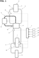
- FIG. 1 is an illustrative view schematically showing a cooling system in a hybrid vehicle according to the present invention.
- an internal combustion engine 1 to be mounted thereon is used for power generation, and an electric motor which is not shown in the drawings drives a drive wheel which is not shown in the drawings.
- the hybrid vehicle of the present invention is a series hybrid vehicle in which all of the power of internal combustion engine 1 is used for generating electric power.
- Internal combustion engine 1 is connected to a motor generator for generating power which is not shown in the drawings.
- the electric power generated by the power generating motor generator is supplied to a battery 2 mounted on the vehicle and the electric motor for driving the drive wheel.
- the electric motor for driving the drive wheel is driven by the electric power charged in battery 2 or the electric power generated by the power generating motor generator.
- Battery 2 is one in which the charging and discharging of the electric power can be performed.
- the hybrid vehicle includes a first cooling path 3 in which a first cooling water (engine cooling water) as a first refrigerant which is capable of cooling internal combustion engine 1 is circulated, a second cooling path 4 in which a second cooling water (battery cooling water) as a second refrigerant which is capable of cooling battery 2 is circulated, a third cooling path (refrigerant circulating route) 5 in which a third refrigerant that is refrigerant for an air conditioner mounted on the vehicle is circulated, a heat exchanger 6 which is capable of performing heat exchange between the first cooling water, the second cooling water and the third refrigerant, and a control unit 7 as a controller.
- a first cooling water engine cooling water
- second cooling path 4 in which a second cooling water (battery cooling water) as a second refrigerant which is capable of cooling battery 2 is circulated
- a third cooling path (refrigerant circulating route) 5 in which a third refrigerant that is refrigerant for an air conditioner mounted on
- First cooling path 3 includes a first control valve 8 as a control valve for controlling the flow rate of cooling water which flows into heat exchanger 6, a radiator 9 for cooling the first cooling water, a second control valve 10 for controlling the flow rate of cooling water which flows into radiator 9, a first temperature sensor 11 for detecting the temperature of the first cooling water, and a first water pump 12 for circulating the first cooling water.
- a first control valve 8 as a control valve for controlling the flow rate of cooling water which flows into heat exchanger 6, a radiator 9 for cooling the first cooling water, a second control valve 10 for controlling the flow rate of cooling water which flows into radiator 9, a first temperature sensor 11 for detecting the temperature of the first cooling water, and a first water pump 12 for circulating the first cooling water.
- First control valve 8 controls the flow rate of the first cooling water which flows into heat exchanger 6 and serves as a control valve which supplies the first cooling water to heat exchanger 6 in a valve opening state and stops supplying the first cooling water to heat exchanger 6 in a valve closing state.
- Second control valve 10 controls the flow rate of the cooling water which flows into radiator 9 and serves as a control valve which supplies the first cooling water to heat exchanger 6 in a valve opening state and stops supplying the first cooling water to heat exchanger 6 in a valve closing state.
- first control valve 8 and second control valve 10 The opening/closing control of first control valve 8 and second control valve 10 is performed by commands from control unit 7.
- First water pump 12 is an electric pump driven by a command, for example, from control unit 7.
- first water pump 12 may be a mechanical pump driven by the rotation of a crankshaft of internal combustion engine 1.
- Second cooling path 4 includes a second temperature sensor 13 for detecting the temperature of the second cooling water and a second water pump 14 for circulating the second cooling water.
- Second water pump 14 is an electric pump driven by a command sent, for example, from control unit 7.
- Third cooling path 5 includes a compressor 15 for compressing the third refrigerant and a third temperature sensor 16 for detecting the temperature of the circulating third refrigerant.
- Compressor 15 is driven by a command from control unit 7 in accordance, for example, with an operation condition of an air conditioner.
- control unit 7 is configured to control the operation of internal combustion engine 1. Specifically, control unit 7 controls the operation/stoppage of internal combustion engine 1 and the load and engine rotation speed of internal combustion engine 1. In addition, control unit 7 is capable of detecting an SOC (State of Charge) that is the ratio of a remaining charge amount to the charge capacity of battery 2.
- SOC State of Charge
- the first cooling water exchanges heat with the second cooling water and the third refrigerant via heat exchanger 6 by opening first control valve 8.
- the second cooling water exchanges heat with the third refrigerant via heat exchanger 6. That is, the hybrid vehicle is configured such that the second cooling water inside second cooling path 4 is cooled by the third refrigerant inside third cooling path 5.
- FIG. 2 is a characteristic diagram showing the correlation between the SOC of battery 2 and the output of battery 2. As shown in FIG. 2 , under the same temperature, the larger the SOC of battery 2 is, the larger the output of battery 2 is. In addition, under the same SOC, the higher the temperature of battery 2 is, the larger the output of battery 2 is. That is, in battery 2, the higher the SOC is, the higher the output is, and the lower the temperature is, the lower the output is.
- the output of battery 2 is equal to or higher than the guaranteed output, internal engine 1 is stopped, and EV traveling in which a drive wheel is driven with only electric power from battery 2 by driving an electric motor can be performed.
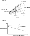
- FIG. 3 is a characteristic diagram showing the correlation between the degree of deterioration of battery 2 and the cycle number of the input and output of battery 2.
- a characteristic line A shown by a broken line in FIG. 3 indicates a case where the temperature of battery 2 is a standard temperature (for example, 25 °C).
- a characteristic line B shown by an alternate long and short dash line in FIG. 3 indicates a case where the temperature of battery 2 is high (for example, 45 °C).
- a state in which battery 2 is new is set as a reference (100%), and it is defined that the degree of deterioration of battery 2 progresses as it becomes small.
- the cycle number of the input and output of battery 2 is, for example, the number of times that the SOC of battery 2 becomes 0% from 100%, and, in other words, it is the number of times of repetition of charge and discharge.
- the warm-up of battery 2 is controlled in consideration of the SOC of battery 2 and the temperature of battery 2. That is, in the hybrid vehicle, when the SOC of battery 2 is at a predetermined value and the output of battery 2 is lower than a preset predetermined first threshold value (guaranteed output), the second cooling water is warmed by the first cooling water in first cooling path 3 to warm up battery 2. Specifically, in the hybrid vehicle, when the output of battery 2 is lower than the first threshold value (guaranteed output) at the time when, for example, the SOC of battery 2 reaches a preset predetermined value, first control valve 8 is opened, and the heat exchange between the first cooling water and the second cooling water is carried out by heat exchanger 6.
- the second cooling water in second cooling path 4 is warmed by the first cooling water in first cooling path 3, and battery 2 can be warmed up, thereby suppressing the lowering of the output of battery 2 due to the lowering of the temperature of battery 2.
- the output of battery 2 is equal to or higher than the first threshold value, EV traveling performed in a state in which internal combustion engine 1 is stopped is ensured.
- the output (characteristic) of battery 2 at the time of an engine cold condition can be improved, and acceleration performance (at the time of, for example, starting) and traveling performance at the time of hill climbing can be improved (enhanced).
- control unit 7 calculates a requested heat amount requested for the warm-up of battery 2 from the temperature of battery 2 and the thermal capacity of battery 2, and controls the rotation speed and the load (operation point) of internal combustion engine 1 at the time of the warm-up of battery 2 according to the requested heat amount.
- the requested heat amount is a value in which, for example, the temperature of battery 2 reaches at least the standard temperature.
- the temperature of battery 2 can be increased with the minimum fuel, and thereby the fuel consumption of internal combustion engine 1 with the warm-up of battery 2 can be suppressed.
- Control unit 7 performs heat exchange between the first cooling water and the second cooling water via heat exchanger 6 by opening first control valve 8 according to the temperature of battery 2 and the temperature of the second cooling water, when battery 2 is warmed up.
- control unit 7 performs the heat exchange between the first cooling water and the second cooling water via heat exchanger 6 by opening first control valve 8 when the temperature of the first cooling water reaches a temperature equal to or higher than a present predetermined first temperature and the temperature of the second cooling water and the temperature of battery 2 reach a temperature equal to or lower than the standard temperature.
- control unit 7 controls first control valve 8 so as to start the heat exchange between the first cooling water and the second cooling water after the temperature of the first cooling water increases.
- control unit 7 stops (ends) the heat exchange between the first cooling water and the second cooling water which is performed via heat exchanger 6 at the time of the warm-up of battery 2, when the temperature of the second cooling water and the temperature of battery 2 reach the standard temperature. That is, control unit 7 ends the warm-up of battery 2 by closing first control valve 8, when the temperature of the second cooling water and the temperature of battery 2 reach the standard temperature.
- the heat exchange between the first cooling water and the second cooling water is performed also in taking account of the temperature of the second cooling water, as compared with a case where it is performed only in taking account of one of the values of the temperature of battery 2 and the temperature of the second cooling water, the deterioration of battery 2 can be suppressed.
- FIG. 4 is a timing chart showing an example of a change in the SOC of battery 2 and the like at the time of the warm-up of battery 2.
- a characteristic line T1 in FIG. 4 indicates a temperature of the second cooling water.
- a characteristic line T2 in FIG. 4 indicates a temperature of battery 2.
- a time t1 is a timing of the start of internal combustion engine 1.
- the SOC of battery 2 at time t1 is at a preset predetermined value.
- the output of battery 2 at time t1 is lower than the first threshold value.
- First control valve 8 is kept in a valve closing state, at time t1.
- the temperature of the first cooling water increases from the timing at time t1 by the start of internal combustion engine 1.
- second control valve 10 becomes a valve opening state at time T1.
- a time t2 is a timing at which the temperature of the first cooling water reaches a first predetermined temperature and first control valve 8 is opened.
- a time t3 is a timing at which internal combustion engine 1 which has been started for the warm-up of battery 2 is stopped.
- the requested heat amount is determined by the engine rotation speed, the load and the drive time of internal combustion engine 1. That is, time t3 is a timing at which the drive time of internal combustion engine 1 with t1 as a starting point which is determined according to the requested heat amount has elapsed.
- a time t4 is a timing at which the temperature of battery 2 reaches the standard temperature and a timing at which first control valve 8 is closed.
- FIG. 5 is a flow chart showing an example of a control flow at the time of the warm-up of battery 2.
- a step S1 it is determined whether or not the output of battery 2 is lower than the first threshold value (guaranteed output) when battery 2 is at a predetermined SOC.
- the step proceeds to a step S2.
- the routine of this time is ended.
- a step S2 the temperature of battery 2 is detected.
- the requested heat amount is calculated.
- internal combustion engine 1 is started. Internal combustion engine 1 is operated at a driving point (engine rotation speed, load) according to the requested heat amount for a driving time according to the requested heat amount.
- a step S5 the temperature of the first cooling water is detected.
- a step S6 the temperature of the second cooling water is detected.
- step S7 it is determined whether or not the temperature of the first cooling water is equal to or higher than the first predetermined temperature and the temperature of battery 2 and the temperature of the second cooling water are lower than the standard temperature.
- step S7 when it is determined that the temperature of the first cooling water is equal to or higher than the first predetermined temperature and the temperature of battery 2 and the temperature of the second cooling water are lower than the standard temperature, the step proceeds to a step S8.
- step S7 when it is not determined that the temperature of the first cooling water is equal to or higher than the first predetermined temperature and the temperature of battery 2 and the temperature of the second cooling water are lower than the standard temperature, the routine of this time is ended.
- step S8 first control valve 8 is opened to start the warm-up of battery 2.
- step S9 the temperature of battery 2 is detected.
- step S10 the temperature of the second cooling water is detected.
- step S11 it is determined whether or not the temperature of battery 2 and the temperature of the second cooling water are equal to or higher than the standard temperature.
- step S11 when it is determined that the temperature of battery 2 and the temperature of the second cooling water are equal to or higher than the standard temperature, the step proceeds to a step S12.
- step S11 when it is not determined that the temperature of battery 2 and the temperature of the second cooling water are equal to or higher than the standard temperature, the step proceeds to step S9.
- step S12 first control valve 8 is closed, and then the warm-up of battery 2 is ended.
- control unit 7 may be configured such that, by using the heat capacity of first cooling path 3 and the heat capacity of second cooling path 4 before the opening of first control valve 8, the temperature of battery 2 and a refrigerant equilibrium temperature that is an equilibrium temperature of the first cooling water and the second cooling water when first control valve 8 is opened are estimated (calculated), and when the temperature of the first cooling water reaches a temperature equal to or higher than the preset first predetermined temperature and the refrigerant equilibrium temperature and the temperature of battery 2 become the standard temperature (for example, 25 °C) or lower, the heat exchange between the first cooling water and the second cooling water is performed via heat exchanger 6 at the time of the warm-up of battery 2.
- control unit 7 may start the warm-up of battery 2 by opening first control valve 8 when the temperature of the first cooling water becomes the first predetermined temperature or higher by the start of internal combustion engine 1 and the refrigerant equilibrium temperature and the temperature of battery 2 become the standard temperature or lower.
- control unit 7 may be configured to stop (end) the heat exchange between the first cooling water and the second cooling water which is performed via heat exchanger 6, when the heat exchange between the first cooling water and the second cooling water via heat exchanger 6 is being performed even if the temperature of battery 2 is higher than the standard temperature and becomes a value obtained by subtracting self-heating temperature (value) of battery 2 from the allowable temperature of battery 2. That is, when the heat exchange between the first cooling water and the second cooling water is being performed via heat exchanger 6 even if the temperature of battery 2 is higher than the standard temperature and becomes a value obtained by subtracting self-heating temperature (value) of battery 2 from the allowable temperature of battery 2, control unit 7 may close first control valve 8.
- the hybrid vehicle has a failsafe function for stopping the heat exchange between the first cooling water and the second cooling water which is performed via heat exchanger 6, and thereby the function of battery 2 can be ensured.
- the allowable temperature of battery 2 is determined by the type of battery 2.
- the temperature of battery 2 is not directly detected by battery temperature sensor 17 but may be estimated based, for example, on detection signals of existing sensors, such as second temperature sensor 13, and a driving history.
- Second cooling path 4 may have a radiator for cooling battery cooling water in case where the battery cooling water is not cooled by the heat exchange with the refrigerant inside third cooling path 5.
- the hybrid vehicle mentioned above may be configured such that second control valve 10 is formed to serve as a mechanical thermostat and first cooling path 3 has a bypass path for bypassing radiator 9.
- second control valve 10 is formed to serve as a mechanical thermostat and first cooling path 3 has a bypass path for bypassing radiator 9.
- engine cooling water can be circulated inside first cooling path 3 while bypassing radiator 9 when the temperature of the engine cooling water is low, so as to quickly increase the temperature of the engine cooling water.
- the embodiment mentioned above relates to a hybrid vehicle control method and a hybrid vehicle control system.
Landscapes
- Engineering & Computer Science (AREA)
- Chemical & Material Sciences (AREA)
- Transportation (AREA)
- Mechanical Engineering (AREA)
- Combustion & Propulsion (AREA)
- Chemical Kinetics & Catalysis (AREA)
- Manufacturing & Machinery (AREA)
- Electrochemistry (AREA)
- General Chemical & Material Sciences (AREA)
- Power Engineering (AREA)
- Automation & Control Theory (AREA)
- Life Sciences & Earth Sciences (AREA)
- Sustainable Development (AREA)
- Sustainable Energy (AREA)
- Hybrid Electric Vehicles (AREA)
- Electric Propulsion And Braking For Vehicles (AREA)
Abstract
Description
- The present invention relates to a method for controlling a hybrid vehicle and a hybrid vehicle control system.
- For example, in a
patent document 1, there is disclosed a configuration in which, by opening a bypass valve, a battery pack (battery) is heated (warmed up) via a heat exchanger by cooling water of an internal combustion engine. - In the
patent document 1, the opening/closing control of the bypass valve is carried out based on a detection value of a battery pack temperature sensor for detecting the temperature of the battery pack. - However, in such a hybrid car of the
patent document 1, when abnormality occurs in the temperature detection of the battery pack (battery), the opening/closing of the bypass valve is incorrectly controlled, and a deterioration in the output of the battery pack might occur due to a decrease in the temperature of the battery pack. - That is, there is room for improvement on the warm-up of a battery using cooling water of an internal combustion engine in order to suppress a deterioration in the output of the battery.
- Patent Document 1:
Japanese Patent Application Publication No. 2008-290636 - In a hybrid vehicle of the present invention, when a battery is in a preset predetermined SOC and the output of the battery is lower than a preset predetermined first threshold value at the time when the internal combustion engine is stopped, the internal combustion engine is started, and, by opening a control valve, the heat exchange between a first refrigerant for cooling the internal combustion engine and a second refrigerant for cooling the battery is carried out.
- In the hybrid vehicle of the present invention, the second refrigerant is warmed by the first refrigerant so as to warm up the battery, thereby suppressing a deterioration in the output of the battery due to a decrease in the temperature of the battery.
-
-
FIG. 1 is an illustrative view schematically showing a cooling system in a hybrid vehicle according to the present invention. -
FIG. 2 is a characteristic diagram showing the correlation between the SOC of a battery and the output of the battery. -
FIG. 3 is a characteristic diagram showing the correlation between the degree of deterioration of the battery and the cycle number of the input and output of the battery. -
FIG. 4 is a timing chart showing an example of a change in the SOC of the battery and the like at the time of the warm-up of the battery. -
FIG. 5 is a flow chart showing an example of a control flow at the time of the warm-up of the battery. - In the following, an embodiment of the present invention will be explained in detail based on the drawings.
-
FIG. 1 is an illustrative view schematically showing a cooling system in a hybrid vehicle according to the present invention. - In the hybrid vehicle according to the present invention, an
internal combustion engine 1 to be mounted thereon is used for power generation, and an electric motor which is not shown in the drawings drives a drive wheel which is not shown in the drawings. That is, the hybrid vehicle of the present invention is a series hybrid vehicle in which all of the power ofinternal combustion engine 1 is used for generating electric power.Internal combustion engine 1 is connected to a motor generator for generating power which is not shown in the drawings. The electric power generated by the power generating motor generator is supplied to abattery 2 mounted on the vehicle and the electric motor for driving the drive wheel. The electric motor for driving the drive wheel is driven by the electric power charged inbattery 2 or the electric power generated by the power generating motor generator.Battery 2 is one in which the charging and discharging of the electric power can be performed. - The hybrid vehicle includes a
first cooling path 3 in which a first cooling water (engine cooling water) as a first refrigerant which is capable of coolinginternal combustion engine 1 is circulated, asecond cooling path 4 in which a second cooling water (battery cooling water) as a second refrigerant which is capable of coolingbattery 2 is circulated, a third cooling path (refrigerant circulating route) 5 in which a third refrigerant that is refrigerant for an air conditioner mounted on the vehicle is circulated, aheat exchanger 6 which is capable of performing heat exchange between the first cooling water, the second cooling water and the third refrigerant, and acontrol unit 7 as a controller. -
First cooling path 3 includes afirst control valve 8 as a control valve for controlling the flow rate of cooling water which flows intoheat exchanger 6, aradiator 9 for cooling the first cooling water, asecond control valve 10 for controlling the flow rate of cooling water which flows intoradiator 9, afirst temperature sensor 11 for detecting the temperature of the first cooling water, and afirst water pump 12 for circulating the first cooling water. -
First control valve 8 controls the flow rate of the first cooling water which flows intoheat exchanger 6 and serves as a control valve which supplies the first cooling water toheat exchanger 6 in a valve opening state and stops supplying the first cooling water toheat exchanger 6 in a valve closing state. -
Second control valve 10 controls the flow rate of the cooling water which flows intoradiator 9 and serves as a control valve which supplies the first cooling water toheat exchanger 6 in a valve opening state and stops supplying the first cooling water toheat exchanger 6 in a valve closing state. - The opening/closing control of
first control valve 8 andsecond control valve 10 is performed by commands fromcontrol unit 7. -
First water pump 12 is an electric pump driven by a command, for example, fromcontrol unit 7. In addition,first water pump 12 may be a mechanical pump driven by the rotation of a crankshaft ofinternal combustion engine 1. -
Second cooling path 4 includes asecond temperature sensor 13 for detecting the temperature of the second cooling water and asecond water pump 14 for circulating the second cooling water. -
Second water pump 14 is an electric pump driven by a command sent, for example, fromcontrol unit 7. -
Third cooling path 5 includes acompressor 15 for compressing the third refrigerant and athird temperature sensor 16 for detecting the temperature of the circulating third refrigerant.Compressor 15 is driven by a command fromcontrol unit 7 in accordance, for example, with an operation condition of an air conditioner. - Detection signals of various sensors such as
first temperature sensor 11,second temperature sensor 13,third temperature sensor 16 and abattery temperature sensor 17 for detecting the temperature ofbattery 2 are input tocontrol unit 7. In addition,control unit 7 is configured to control the operation ofinternal combustion engine 1. Specifically,control unit 7 controls the operation/stoppage ofinternal combustion engine 1 and the load and engine rotation speed ofinternal combustion engine 1. In addition,control unit 7 is capable of detecting an SOC (State of Charge) that is the ratio of a remaining charge amount to the charge capacity ofbattery 2. - The first cooling water exchanges heat with the second cooling water and the third refrigerant via
heat exchanger 6 by openingfirst control valve 8. - The second cooling water exchanges heat with the third refrigerant via
heat exchanger 6. That is, the hybrid vehicle is configured such that the second cooling water insidesecond cooling path 4 is cooled by the third refrigerant insidethird cooling path 5. -
FIG. 2 is a characteristic diagram showing the correlation between the SOC ofbattery 2 and the output ofbattery 2. As shown inFIG. 2 , under the same temperature, the larger the SOC ofbattery 2 is, the larger the output ofbattery 2 is. In addition, under the same SOC, the higher the temperature ofbattery 2 is, the larger the output ofbattery 2 is. That is, inbattery 2, the higher the SOC is, the higher the output is, and the lower the temperature is, the lower the output is. - Therefore, in
battery 2, the lower the temperature becomes, the higher the value of the SOC which satisfies the guaranteed output (minimum guaranteed output) ofbattery 2 becomes. In the hybrid vehicle, when the output ofbattery 2 is equal to or higher than the guaranteed output,internal engine 1 is stopped, and EV traveling in which a drive wheel is driven with only electric power frombattery 2 by driving an electric motor can be performed. -
FIG. 3 is a characteristic diagram showing the correlation between the degree of deterioration ofbattery 2 and the cycle number of the input and output ofbattery 2. A characteristic line A shown by a broken line inFIG. 3 indicates a case where the temperature ofbattery 2 is a standard temperature (for example, 25 °C). A characteristic line B shown by an alternate long and short dash line inFIG. 3 indicates a case where the temperature ofbattery 2 is high (for example, 45 °C). For example, a state in whichbattery 2 is new is set as a reference (100%), and it is defined that the degree of deterioration ofbattery 2 progresses as it becomes small. The cycle number of the input and output ofbattery 2 is, for example, the number of times that the SOC ofbattery 2 becomes 0% from 100%, and, in other words, it is the number of times of repetition of charge and discharge. - As shown in
FIG. 3 , when the temperature ofbattery 2 is high, the deterioration ofbattery 2 is accelerated. - Therefore, in the hybrid vehicle, the warm-up of
battery 2 is controlled in consideration of the SOC ofbattery 2 and the temperature ofbattery 2. That is, in the hybrid vehicle, when the SOC ofbattery 2 is at a predetermined value and the output ofbattery 2 is lower than a preset predetermined first threshold value (guaranteed output), the second cooling water is warmed by the first cooling water infirst cooling path 3 to warm upbattery 2. Specifically, in the hybrid vehicle, when the output ofbattery 2 is lower than the first threshold value (guaranteed output) at the time when, for example, the SOC ofbattery 2 reaches a preset predetermined value,first control valve 8 is opened, and the heat exchange between the first cooling water and the second cooling water is carried out byheat exchanger 6. - Accordingly, in the hybrid vehicle, the second cooling water in
second cooling path 4 is warmed by the first cooling water infirst cooling path 3, andbattery 2 can be warmed up, thereby suppressing the lowering of the output ofbattery 2 due to the lowering of the temperature ofbattery 2. In the hybrid vehicle, when the output ofbattery 2 is equal to or higher than the first threshold value, EV traveling performed in a state in whichinternal combustion engine 1 is stopped is ensured. - In
battery 2, when the first cooling water is warmed up and the output (characteristic) ofbattery 2 is improved, the time until the output ofbattery 2 reaches a value lower than the first threshold value (guaranteed output) can be prolonged. Consequently, in the hybrid vehicle, EV traveling performed in a state in whichinternal combustion engine 1 is stopped can be carried out for a long time. - In addition, in the hybrid vehicle, the output (characteristic) of
battery 2 at the time of an engine cold condition can be improved, and acceleration performance (at the time of, for example, starting) and traveling performance at the time of hill climbing can be improved (enhanced). - In
battery 2, the lower the temperature ofbattery 2 becomes, the lower the amount of chargeable electric power becomes. Consequently, in the hybrid vehicle, when the temperature ofbattery 2 is low and the amount of the electric power chargeable tobattery 2 is low, for example, by operating friction brake, kinetic energy is converted to heat energy and it is consumed so as to reduce a regeneration amount. - However, in the hybrid vehicle, since the regeneration amount at the time of an extremely low temperature can be increased by the warm-up of
battery 2, kinetic energy generated by deceleration can be stably recovered. - In addition,
control unit 7 calculates a requested heat amount requested for the warm-up ofbattery 2 from the temperature ofbattery 2 and the thermal capacity ofbattery 2, and controls the rotation speed and the load (operation point) ofinternal combustion engine 1 at the time of the warm-up ofbattery 2 according to the requested heat amount. In addition, the requested heat amount is a value in which, for example, the temperature ofbattery 2 reaches at least the standard temperature. - Consequently, in the hybrid vehicle, by calculating a heat amount requested for the warm-up of
battery 2, the temperature ofbattery 2 can be increased with the minimum fuel, and thereby the fuel consumption ofinternal combustion engine 1 with the warm-up ofbattery 2 can be suppressed. - In addition, in the hybrid vehicle, it is possible to suppress excessive temperature rise of
battery 2, thereby suppressing the deterioration ofbattery 2 caused by the temperature rise ofbattery 2. -
Control unit 7 performs heat exchange between the first cooling water and the second cooling water viaheat exchanger 6 by openingfirst control valve 8 according to the temperature ofbattery 2 and the temperature of the second cooling water, whenbattery 2 is warmed up. - Specifically,
control unit 7 performs the heat exchange between the first cooling water and the second cooling water viaheat exchanger 6 by openingfirst control valve 8 when the temperature of the first cooling water reaches a temperature equal to or higher than a present predetermined first temperature and the temperature of the second cooling water and the temperature ofbattery 2 reach a temperature equal to or lower than the standard temperature. In other words, controlunit 7 controlsfirst control valve 8 so as to start the heat exchange between the first cooling water and the second cooling water after the temperature of the first cooling water increases. - In addition,
control unit 7 stops (ends) the heat exchange between the first cooling water and the second cooling water which is performed viaheat exchanger 6 at the time of the warm-up ofbattery 2, when the temperature of the second cooling water and the temperature ofbattery 2 reach the standard temperature. That is,control unit 7 ends the warm-up ofbattery 2 by closingfirst control valve 8, when the temperature of the second cooling water and the temperature ofbattery 2 reach the standard temperature. - Consequently, in the hybrid vehicle, a deterioration in
battery 2 caused by the excessive increasing of the temperature ofbattery 2 can be suppressed, and thereby the function ofbattery 2 can be guaranteed. - In the hybrid vehicle, since the heat exchange between the first cooling water and the second cooling water is performed also in taking account of the temperature of the second cooling water, as compared with a case where it is performed only in taking account of one of the values of the temperature of
battery 2 and the temperature of the second cooling water, the deterioration ofbattery 2 can be suppressed. -
FIG. 4 is a timing chart showing an example of a change in the SOC ofbattery 2 and the like at the time of the warm-up ofbattery 2. A characteristic line T1 inFIG. 4 indicates a temperature of the second cooling water. A characteristic line T2 inFIG. 4 indicates a temperature ofbattery 2. - A time t1 is a timing of the start of
internal combustion engine 1. The SOC ofbattery 2 at time t1 is at a preset predetermined value. In addition, the output ofbattery 2 at time t1 is lower than the first threshold value.First control valve 8 is kept in a valve closing state, at time t1. The temperature of the first cooling water increases from the timing at time t1 by the start ofinternal combustion engine 1. In addition,second control valve 10 becomes a valve opening state at time T1. - A time t2 is a timing at which the temperature of the first cooling water reaches a first predetermined temperature and
first control valve 8 is opened. - A time t3 is a timing at which
internal combustion engine 1 which has been started for the warm-up ofbattery 2 is stopped. The requested heat amount is determined by the engine rotation speed, the load and the drive time ofinternal combustion engine 1. That is, time t3 is a timing at which the drive time ofinternal combustion engine 1 with t1 as a starting point which is determined according to the requested heat amount has elapsed. - A time t4 is a timing at which the temperature of
battery 2 reaches the standard temperature and a timing at whichfirst control valve 8 is closed. -
FIG. 5 is a flow chart showing an example of a control flow at the time of the warm-up ofbattery 2. - In a step S1, it is determined whether or not the output of
battery 2 is lower than the first threshold value (guaranteed output) whenbattery 2 is at a predetermined SOC. When it is determined that the output ofbattery 2 is lower than the first threshold value when the SOC ofbattery 2 is at a preset predetermined value in step S1, the step proceeds to a step S2. When it is not determined that the output ofbattery 2 is lower than the first threshold value when the SOC ofbattery 2 is at a preset predetermined value in step S1, the routine of this time is ended. - In a step S2, the temperature of
battery 2 is detected. In a step S3, the requested heat amount is calculated. In a step S4,internal combustion engine 1 is started.Internal combustion engine 1 is operated at a driving point (engine rotation speed, load) according to the requested heat amount for a driving time according to the requested heat amount. In a step S5, the temperature of the first cooling water is detected. In a step S6, the temperature of the second cooling water is detected. - In a step S7, it is determined whether or not the temperature of the first cooling water is equal to or higher than the first predetermined temperature and the temperature of
battery 2 and the temperature of the second cooling water are lower than the standard temperature. In step S7, when it is determined that the temperature of the first cooling water is equal to or higher than the first predetermined temperature and the temperature ofbattery 2 and the temperature of the second cooling water are lower than the standard temperature, the step proceeds to a step S8. In step S7, when it is not determined that the temperature of the first cooling water is equal to or higher than the first predetermined temperature and the temperature ofbattery 2 and the temperature of the second cooling water are lower than the standard temperature, the routine of this time is ended. - In step S8,
first control valve 8 is opened to start the warm-up ofbattery 2. In a step S9, the temperature ofbattery 2 is detected. In a step S10, the temperature of the second cooling water is detected. - In a step S11, it is determined whether or not the temperature of
battery 2 and the temperature of the second cooling water are equal to or higher than the standard temperature. In step S11, when it is determined that the temperature ofbattery 2 and the temperature of the second cooling water are equal to or higher than the standard temperature, the step proceeds to a step S12. In step S11, when it is not determined that the temperature ofbattery 2 and the temperature of the second cooling water are equal to or higher than the standard temperature, the step proceeds to step S9. - In step S12,
first control valve 8 is closed, and then the warm-up ofbattery 2 is ended. - As the above, although a specific embodiment of the present invention has been explained, the present invention is not limited to the embodiment mentioned above, and various changes might be made to the embodiment without departing from the scope and spirit of the present invention.
- For example,
control unit 7 may be configured such that, by using the heat capacity offirst cooling path 3 and the heat capacity ofsecond cooling path 4 before the opening offirst control valve 8, the temperature ofbattery 2 and a refrigerant equilibrium temperature that is an equilibrium temperature of the first cooling water and the second cooling water whenfirst control valve 8 is opened are estimated (calculated), and when the temperature of the first cooling water reaches a temperature equal to or higher than the preset first predetermined temperature and the refrigerant equilibrium temperature and the temperature ofbattery 2 become the standard temperature (for example, 25 °C) or lower, the heat exchange between the first cooling water and the second cooling water is performed viaheat exchanger 6 at the time of the warm-up ofbattery 2. That is,control unit 7 may start the warm-up ofbattery 2 by openingfirst control valve 8 when the temperature of the first cooling water becomes the first predetermined temperature or higher by the start ofinternal combustion engine 1 and the refrigerant equilibrium temperature and the temperature ofbattery 2 become the standard temperature or lower. - In addition,
control unit 7 may be configured to stop (end) the heat exchange between the first cooling water and the second cooling water which is performed viaheat exchanger 6, when the heat exchange between the first cooling water and the second cooling water viaheat exchanger 6 is being performed even if the temperature ofbattery 2 is higher than the standard temperature and becomes a value obtained by subtracting self-heating temperature (value) ofbattery 2 from the allowable temperature ofbattery 2. That is, when the heat exchange between the first cooling water and the second cooling water is being performed viaheat exchanger 6 even if the temperature ofbattery 2 is higher than the standard temperature and becomes a value obtained by subtracting self-heating temperature (value) ofbattery 2 from the allowable temperature ofbattery 2,control unit 7 may closefirst control valve 8. - Accordingly, the hybrid vehicle has a failsafe function for stopping the heat exchange between the first cooling water and the second cooling water which is performed via
heat exchanger 6, and thereby the function ofbattery 2 can be ensured. In addition, the allowable temperature ofbattery 2 is determined by the type ofbattery 2. - For example, the temperature of
battery 2 is not directly detected bybattery temperature sensor 17 but may be estimated based, for example, on detection signals of existing sensors, such assecond temperature sensor 13, and a driving history. -
Second cooling path 4 may have a radiator for cooling battery cooling water in case where the battery cooling water is not cooled by the heat exchange with the refrigerant insidethird cooling path 5. - In addition, the hybrid vehicle mentioned above may be configured such that
second control valve 10 is formed to serve as a mechanical thermostat andfirst cooling path 3 has a bypass path for bypassingradiator 9. In this case, in this hybrid vehicle, at the time of the warm-up ofbattery 2, engine cooling water can be circulated insidefirst cooling path 3 while bypassingradiator 9 when the temperature of the engine cooling water is low, so as to quickly increase the temperature of the engine cooling water. - The embodiment mentioned above relates to a hybrid vehicle control method and a hybrid vehicle control system.
Claims (7)
- A method for controlling a hybrid vehicle, wherein the hybrid vehicle comprises: an internal combustion engine for power generation; a first cooling path in which a first refrigerant which is capable of cooling the internal combustion engine is circulated; a battery for charging and discharging electric power; a second cooling path in which a second refrigerant which is capable of cooling the battery is circulated; a heat exchanger for performing heat exchange between the first refrigerant and the second refrigerant; and a control valve provided in the first cooling path, and configured to supply the first refrigerant to the heat exchanger in a valve opening state and to stop supplying the first refrigerant to the heat exchanger in a valve closing state, the hybrid vehicle control method comprising:
starting the internal combustion engine and opening the control valve to perform the heat exchange between the first refrigerant and the second refrigerant when the battery reaches at a preset predetermined SOC and an output of the battery is lower than a preset predetermined first threshold value, when the internal combustion engine has been stopped. - The method for controlling the hybrid vehicle according to claim 1, wherein a requested heat amount requested for warm-up of the battery is calculated from a temperature of the battery and a heat capacity of the battery, and
wherein a rotation speed and a load of the internal combustion engine are controlled according to the requested heat amount. - The method for controlling the hybrid vehicle according to claim 1 or 2, wherein the control valve (8) is opened and closed according to the temperature of the battery (2) and a temperature of the second refrigerant, so as to perform the heat exchange between the first refrigerant and the second refrigerant.
- The method for controlling the hybrid vehicle according to claim 3, wherein, by using a heat capacity of the first cooling path and a heat capacity of the second cooling path before the opening of the control valve, an equilibrium temperature between the first refrigerant and the second refrigerant and the temperature of the battery are estimated, and when the equilibrium temperature and the temperature of the battery reach a predetermined standard temperature or lower, the heat exchange between the first refrigerant and the second refrigerant is performed.
- The method for controlling the hybrid vehicle according to claim 4, wherein when the temperature of the second refrigerant and the temperature of the battery reach the predetermined standard temperature, the heat exchange between the first refrigerant and the second refrigerant is stopped.
- The method for controlling the hybrid vehicle according to claim 5, wherein when the heat exchange between the first refrigerant and the second refrigerant is being performed even if the temperature of the battery is higher than the standard temperature and becomes a value obtained by subtracting a self-heating temperature of the battery from an allowable temperature of the battery, the heat exchange between the first refrigerant and the second refrigerant is stopped.
- A hybrid vehicle control system, comprising:an internal combustion engine for power generation;a first cooling path in which a first refrigerant which is capable of cooling the internal combustion engine is circulated;a battery for charging and discharging electric power;a second cooling path in which a second refrigerant which is capable of cooling the battery is circulated;a heat exchanger for performing heat exchange between the first refrigerant and the second refrigerant;a control valve provided in the first cooling path, and configured to supply the first refrigerant to the heat exchanger in a valve opening state and to stop supplying the first refrigerant to the heat exchanger in a valve closing state; anda controller configured to start the internal combustion engine and open the control valve to perform the heat exchange between the first refrigerant and the second refrigerant when the battery reaches at a preset predetermined SOC and an output of the battery is lower than a preset predetermined first threshold value, when the internal combustion engine has been stopped.
Applications Claiming Priority (1)
| Application Number | Priority Date | Filing Date | Title |
|---|---|---|---|
| PCT/JP2022/010153 WO2023170804A1 (en) | 2022-03-09 | 2022-03-09 | Hybrid vehicle control method and hybrid vehicle control device |
Publications (2)
| Publication Number | Publication Date |
|---|---|
| EP4491474A1 true EP4491474A1 (en) | 2025-01-15 |
| EP4491474A4 EP4491474A4 (en) | 2025-04-30 |
Family
ID=87936283
Family Applications (1)
| Application Number | Title | Priority Date | Filing Date |
|---|---|---|---|
| EP22930151.0A Withdrawn EP4491474A4 (en) | 2022-03-09 | 2022-03-09 | HYBRID VEHICLE CONTROL METHOD AND HYBRID VEHICLE CONTROL DEVICE |
Country Status (5)
| Country | Link |
|---|---|
| US (1) | US20250033528A1 (en) |
| EP (1) | EP4491474A4 (en) |
| JP (1) | JP7747168B2 (en) |
| CN (1) | CN118742474A (en) |
| WO (1) | WO2023170804A1 (en) |
Families Citing this family (1)
| Publication number | Priority date | Publication date | Assignee | Title |
|---|---|---|---|---|
| CN119975324B (en) * | 2025-03-28 | 2025-10-31 | 一汽解放汽车有限公司 | Driving method, device, equipment and medium for hybrid electric vehicle |
Family Cites Families (13)
| Publication number | Priority date | Publication date | Assignee | Title |
|---|---|---|---|---|
| JP4501667B2 (en) * | 2004-12-14 | 2010-07-14 | 三菱電機株式会社 | Vehicle drive device |
| JP4958637B2 (en) | 2007-05-26 | 2012-06-20 | 三洋電機株式会社 | Hybrid car |
| JP5482436B2 (en) * | 2009-06-12 | 2014-05-07 | 株式会社デンソー | Engine waste heat control device |
| JP5659990B2 (en) * | 2011-09-12 | 2015-01-28 | 三菱自動車工業株式会社 | Battery temperature control device |
| JP5929699B2 (en) * | 2012-10-18 | 2016-06-08 | トヨタ自動車株式会社 | Control device for hybrid vehicle |
| US9587546B2 (en) * | 2013-10-02 | 2017-03-07 | Ford Global Technologies, Llc | Methods and systems for hybrid vehicle waste heat recovery |
| JP6232911B2 (en) * | 2013-10-11 | 2017-11-22 | 株式会社デンソー | Vehicle control device |
| JP6496163B2 (en) * | 2015-03-03 | 2019-04-03 | 日立建機株式会社 | Hybrid construction machine |
| JP6867258B2 (en) * | 2017-09-08 | 2021-04-28 | 本田技研工業株式会社 | Vehicle heat exchange systems, vehicle heat exchange methods, and programs |
| JP2019064566A (en) * | 2017-10-05 | 2019-04-25 | 本田技研工業株式会社 | Battery heating system |
| CN112026588B (en) * | 2019-11-28 | 2022-05-06 | 长城汽车股份有限公司 | A battery pack control method, system and vehicle |
| JP7534097B2 (en) * | 2020-02-13 | 2024-08-14 | 本田技研工業株式会社 | Control device and program |
| CN117651665A (en) * | 2021-07-26 | 2024-03-05 | 日产自动车株式会社 | Start and stop control method and device for internal combustion engine of hybrid vehicle |
-
2022
- 2022-03-09 CN CN202280092479.9A patent/CN118742474A/en active Pending
- 2022-03-09 JP JP2024505710A patent/JP7747168B2/en active Active
- 2022-03-09 US US18/841,475 patent/US20250033528A1/en active Pending
- 2022-03-09 WO PCT/JP2022/010153 patent/WO2023170804A1/en not_active Ceased
- 2022-03-09 EP EP22930151.0A patent/EP4491474A4/en not_active Withdrawn
Also Published As
| Publication number | Publication date |
|---|---|
| JP7747168B2 (en) | 2025-10-01 |
| WO2023170804A1 (en) | 2023-09-14 |
| CN118742474A (en) | 2024-10-01 |
| JPWO2023170804A1 (en) | 2023-09-14 |
| US20250033528A1 (en) | 2025-01-30 |
| EP4491474A4 (en) | 2025-04-30 |
Similar Documents
| Publication | Publication Date | Title |
|---|---|---|
| US9096207B2 (en) | Hybrid vehicle powertrain cooling system | |
| CN102186711B (en) | Device for controlling hybrid vehicle | |
| JP4478900B1 (en) | Capacitor heating device | |
| KR102257214B1 (en) | Method for operating a cooling system for a hybrid electric vehicle comprising a liquid coolant delivery circuit | |
| CN110198851B (en) | Method for operating a hybrid electric vehicle cooling system including a liquid coolant transfer loop | |
| US9609790B2 (en) | Hybrid vehicle | |
| WO2013101519A1 (en) | Thermal management system for vehicle having traction motor | |
| JP2013055019A (en) | Temperature control device of battery pack | |
| JP6183133B2 (en) | Battery warm-up system | |
| JP2013141337A (en) | Controller for vehicle and vehicle including the same | |
| CN116198285B (en) | Thermal management system, thermal management method, electronic device and vehicle | |
| US20200231135A1 (en) | Vehicle | |
| US10343529B2 (en) | Hybrid vehicle | |
| US20250033528A1 (en) | Hybrid vehicle control method and hybrid vehicle control device | |
| JP7454469B2 (en) | vehicle power system | |
| KR102761291B1 (en) | Control system and method for cooling battery | |
| KR20160022028A (en) | Control method for auto cruise mode of fuel cell vehicle | |
| JP3894180B2 (en) | Hybrid vehicle cooling system | |
| JP7373265B2 (en) | Control device | |
| JP2017152283A (en) | Control device | |
| JP6973934B2 (en) | Vehicle heating system | |
| JP7124722B2 (en) | hybrid car | |
| JPWO2023170804A5 (en) | ||
| JP2016084062A (en) | Hybrid automobile | |
| KR20200110595A (en) | Method of warming up plug-in hybrid electric vehicle in cold weather |
Legal Events
| Date | Code | Title | Description |
|---|---|---|---|
| STAA | Information on the status of an ep patent application or granted ep patent |
Free format text: STATUS: THE INTERNATIONAL PUBLICATION HAS BEEN MADE |
|
| PUAI | Public reference made under article 153(3) epc to a published international application that has entered the european phase |
Free format text: ORIGINAL CODE: 0009012 |
|
| STAA | Information on the status of an ep patent application or granted ep patent |
Free format text: STATUS: REQUEST FOR EXAMINATION WAS MADE |
|
| 17P | Request for examination filed |
Effective date: 20240916 |
|
| AK | Designated contracting states |
Kind code of ref document: A1 Designated state(s): AL AT BE BG CH CY CZ DE DK EE ES FI FR GB GR HR HU IE IS IT LI LT LU LV MC MK MT NL NO PL PT RO RS SE SI SK SM TR |
|
| STAA | Information on the status of an ep patent application or granted ep patent |
Free format text: STATUS: THE APPLICATION HAS BEEN WITHDRAWN |
|
| A4 | Supplementary search report drawn up and despatched |
Effective date: 20250328 |
|
| RIC1 | Information provided on ipc code assigned before grant |
Ipc: B60W 10/30 20060101ALI20250324BHEP Ipc: B60L 58/27 20190101ALI20250324BHEP Ipc: B60L 58/26 20190101ALI20250324BHEP Ipc: B60W 30/188 20120101ALI20250324BHEP Ipc: B60W 20/40 20160101ALI20250324BHEP Ipc: B60W 20/11 20160101ALI20250324BHEP Ipc: B60W 10/08 20060101ALI20250324BHEP Ipc: B60W 10/06 20060101ALI20250324BHEP Ipc: B60L 58/24 20190101ALI20250324BHEP Ipc: B60K 11/02 20060101ALI20250324BHEP Ipc: B60W 20/13 20160101ALI20250324BHEP Ipc: B60K 6/46 20071001ALI20250324BHEP Ipc: B60W 10/26 20060101AFI20250324BHEP |
|
| 18W | Application withdrawn |
Effective date: 20250331 |