EP4491451A1 - Vehicle seat structure - Google Patents
Vehicle seat structure Download PDFInfo
- Publication number
- EP4491451A1 EP4491451A1 EP24186562.5A EP24186562A EP4491451A1 EP 4491451 A1 EP4491451 A1 EP 4491451A1 EP 24186562 A EP24186562 A EP 24186562A EP 4491451 A1 EP4491451 A1 EP 4491451A1
- Authority
- EP
- European Patent Office
- Prior art keywords
- seat
- buckle
- seat section
- section
- vehicle
- Prior art date
- Legal status (The legal status is an assumption and is not a legal conclusion. Google has not performed a legal analysis and makes no representation as to the accuracy of the status listed.)
- Pending
Links
Images




Classifications
-
- B—PERFORMING OPERATIONS; TRANSPORTING
- B60—VEHICLES IN GENERAL
- B60N—SEATS SPECIALLY ADAPTED FOR VEHICLES; VEHICLE PASSENGER ACCOMMODATION NOT OTHERWISE PROVIDED FOR
- B60N2/00—Seats specially adapted for vehicles; Arrangement or mounting of seats in vehicles
- B60N2/24—Seats specially adapted for vehicles; Arrangement or mounting of seats in vehicles for particular purposes or particular vehicles
- B60N2/30—Non-dismountable or dismountable seats storable in a non-use position, e.g. foldable spare seats
- B60N2/3002—Non-dismountable or dismountable seats storable in a non-use position, e.g. foldable spare seats back-rest movements
- B60N2/3004—Non-dismountable or dismountable seats storable in a non-use position, e.g. foldable spare seats back-rest movements by rotation only
- B60N2/3009—Non-dismountable or dismountable seats storable in a non-use position, e.g. foldable spare seats back-rest movements by rotation only about transversal axis
- B60N2/3013—Non-dismountable or dismountable seats storable in a non-use position, e.g. foldable spare seats back-rest movements by rotation only about transversal axis the back-rest being hinged on the vehicle frame
-
- B—PERFORMING OPERATIONS; TRANSPORTING
- B60—VEHICLES IN GENERAL
- B60N—SEATS SPECIALLY ADAPTED FOR VEHICLES; VEHICLE PASSENGER ACCOMMODATION NOT OTHERWISE PROVIDED FOR
- B60N2/00—Seats specially adapted for vehicles; Arrangement or mounting of seats in vehicles
- B60N2/02—Seats specially adapted for vehicles; Arrangement or mounting of seats in vehicles the seat or part thereof being movable, e.g. adjustable
- B60N2/0224—Non-manual adjustments, e.g. with electrical operation
- B60N2/0244—Non-manual adjustments, e.g. with electrical operation with logic circuits
- B60N2/0264—Non-manual adjustments, e.g. with electrical operation with logic circuits characterised by the type of electrical connection, e.g. wiring, plugs or USB
-
- B—PERFORMING OPERATIONS; TRANSPORTING
- B60—VEHICLES IN GENERAL
- B60N—SEATS SPECIALLY ADAPTED FOR VEHICLES; VEHICLE PASSENGER ACCOMMODATION NOT OTHERWISE PROVIDED FOR
- B60N2/00—Seats specially adapted for vehicles; Arrangement or mounting of seats in vehicles
- B60N2/24—Seats specially adapted for vehicles; Arrangement or mounting of seats in vehicles for particular purposes or particular vehicles
- B60N2/30—Non-dismountable or dismountable seats storable in a non-use position, e.g. foldable spare seats
- B60N2/3038—Cushion movements
- B60N2/3063—Cushion movements by composed movement
- B60N2/3065—Cushion movements by composed movement in a longitudinal-vertical plane
-
- B—PERFORMING OPERATIONS; TRANSPORTING
- B60—VEHICLES IN GENERAL
- B60N—SEATS SPECIALLY ADAPTED FOR VEHICLES; VEHICLE PASSENGER ACCOMMODATION NOT OTHERWISE PROVIDED FOR
- B60N2/00—Seats specially adapted for vehicles; Arrangement or mounting of seats in vehicles
- B60N2/58—Seat coverings
-
- B—PERFORMING OPERATIONS; TRANSPORTING
- B60—VEHICLES IN GENERAL
- B60N—SEATS SPECIALLY ADAPTED FOR VEHICLES; VEHICLE PASSENGER ACCOMMODATION NOT OTHERWISE PROVIDED FOR
- B60N2/00—Seats specially adapted for vehicles; Arrangement or mounting of seats in vehicles
- B60N2/58—Seat coverings
- B60N2/60—Removable protective coverings
- B60N2/6009—Removable protective coverings covering more than only the seat
-
- B—PERFORMING OPERATIONS; TRANSPORTING
- B60—VEHICLES IN GENERAL
- B60R—VEHICLES, VEHICLE FITTINGS, OR VEHICLE PARTS, NOT OTHERWISE PROVIDED FOR
- B60R22/00—Safety belts or body harnesses in vehicles
- B60R22/18—Anchoring devices
- B60R22/22—Anchoring devices secured to the vehicle floor
-
- B—PERFORMING OPERATIONS; TRANSPORTING
- B60—VEHICLES IN GENERAL
- B60R—VEHICLES, VEHICLE FITTINGS, OR VEHICLE PARTS, NOT OTHERWISE PROVIDED FOR
- B60R22/00—Safety belts or body harnesses in vehicles
- B60R22/18—Anchoring devices
- B60R22/26—Anchoring devices secured to the seat
-
- B—PERFORMING OPERATIONS; TRANSPORTING
- B60—VEHICLES IN GENERAL
- B60N—SEATS SPECIALLY ADAPTED FOR VEHICLES; VEHICLE PASSENGER ACCOMMODATION NOT OTHERWISE PROVIDED FOR
- B60N2205/00—General mechanical or structural details
- B60N2205/30—Seat or seat parts characterised by comprising plural parts or pieces
- B60N2205/35—Seat, bench or back-rests being split laterally in two or more parts
-
- B—PERFORMING OPERATIONS; TRANSPORTING
- B60—VEHICLES IN GENERAL
- B60R—VEHICLES, VEHICLE FITTINGS, OR VEHICLE PARTS, NOT OTHERWISE PROVIDED FOR
- B60R22/00—Safety belts or body harnesses in vehicles
- B60R22/18—Anchoring devices
- B60R2022/1806—Anchoring devices for buckles
-
- B—PERFORMING OPERATIONS; TRANSPORTING
- B60—VEHICLES IN GENERAL
- B60R—VEHICLES, VEHICLE FITTINGS, OR VEHICLE PARTS, NOT OTHERWISE PROVIDED FOR
- B60R21/00—Arrangements or fittings on vehicles for protecting or preventing injuries to occupants or pedestrians in case of accidents or other traffic risks
- B60R21/01—Electrical circuits for triggering passive safety arrangements, e.g. airbags, safety belt tighteners, in case of vehicle accidents or impending vehicle accidents
- B60R21/015—Electrical circuits for triggering passive safety arrangements, e.g. airbags, safety belt tighteners, in case of vehicle accidents or impending vehicle accidents including means for detecting the presence or position of passengers, passenger seats or child seats, and the related safety parameters therefor, e.g. speed or timing of airbag inflation in relation to occupant position or seat belt use
- B60R21/01512—Passenger detection systems
- B60R21/01544—Passenger detection systems detecting seat belt parameters, e.g. length, tension or height-adjustment
- B60R21/01546—Passenger detection systems detecting seat belt parameters, e.g. length, tension or height-adjustment using belt buckle sensors
Definitions
- the present invention relates to a vehicle seat structure.
- a vehicle may be provided with a seat belt reminder function that gives an alarm, for example, to indicate that an occupant seated on a vehicle seat is not wearing a seat belt by using a detection device for detecting whether or not the seat belt in the vehicle is worn.
- Patent Document 1 the above-described detection is performed by transmitting a signal from a buckle switch installed in a lap-side buckle via a wire harness to an ECU (Electronic Control Unit).
- ECU Electronic Control Unit
- Patent Document 1 JP 2011-126358A
- a seat cushion configured to move as described above is provided with a buckle to which a cord-shaped structure such as a wire harness for detecting whether or not a seat belt is worn is connected, the following problems occur. That is to say, when the seat cushion moves, the wire harness may come into contact with nearby members and may be damaged or deteriorate.
- the position of the buckle provided on the seat cushion naturally changes, and the buckle may be unexpectedly displaced from its predetermined position on the seat cushion.
- the cord-shaped structure such as a wire harness may come into contact with nearby members and be damaged, or the cord-shaped structure may deteriorate due to localized concentration of stress on the cord-shaped structure.
- an object of the present invention is to provide a vehicle seat structure that can more reliably protect a cord-shaped structure routed from a buckle provided on a seat cushion that moves forward and downward when a seat back is inclined forward.
- a representative configuration of the present invention is a vehicle seat structure including: a seat including a seat section on which an occupant of a vehicle sits and a seat back arranged upright from a rear portion of the seat section to support the back of the occupant; a movement mechanism for inclining the seat back forward and moving the seat section forward and downward; and a buckle that is disposed on a lateral side of the seat section and to which a tongue of a seat belt for the occupant can be attached, the vehicle seat structure being characterized in further including: a cord-shaped structure routed from the buckle toward a floor panel; and a flexible guide member extending beside the cord-shaped structure from the buckle to the floor panel to guide a route of the cord-shaped structure.
- a representative configuration of the present invention is a vehicle seat structure including: a seat including a seat section on which an occupant of a vehicle sits and a seat back arranged upright from a rear portion of the seat section to support the back of the occupant; a movement mechanism for inclining the seat back forward and moving the seat section forward and downward; a buckle that is disposed on a lateral side of the seat section and to which a tongue of a seat belt for the occupant can be attached; and a cord-shaped structure routed from the buckle toward a floor panel, the vehicle seat structure being characterized in further including a flexible belt-shaped restriction member covering the buckle in a front-rear direction and fixed to the lateral side of the seat section in front of and behind the buckle to restrict the buckle to the lateral side of the seat section.
- a vehicle seat structure that can more reliably protect a cord-shaped structure routed from a buckle provided on a seat section that moves forward and downward when a seat back is inclined forward.
- An embodiment of the present invention is a vehicle seat structure including: a seat including a seat section on which an occupant of a vehicle sits and a seat back arranged upright from a rear portion of the seat section to support the back of the occupant; a movement mechanism for inclining the seat back forward and moving the seat section forward and downward; and a buckle that is disposed on a lateral side of the seat section and to which a tongue of a seat belt for the occupant can be attached, the vehicle seat structure being characterized in further including: a cord-shaped structure routed from the buckle toward a floor panel; and a flexible guide member extending beside the cord-shaped structure from the buckle to the floor panel to guide a route of the cord-shaped structure.
- the flexible guide member extends beside the cord-shaped structure from the buckle to the floor panel, and therefore, the cord-shaped structure can be prevented from coming into contact with nearby members and deteriorating when the seat section is moved.
- At least a portion of the guide member is adjacent to a lower side of the cord-shaped structure.
- This configuration can prevent, in particular, deterioration of the cord-shaped structure due to contact with the floor panel under the cord-shaped structure when the seat section is moved forward and downward.
- the guide member is a belt-shaped member that is wider than the cord-shaped structure.
- a belt-shaped guide member easily deforms when the seat section is moved and covers a wide range of the cord-shaped structure, and therefore has a high effect of protecting the cord-shaped structure.
- the vehicle seat structure further includes a car body fixing member fixing the guide member to the floor panel at a position spaced apart from the buckle in a front-rear direction, and the guide member has a width arranged along a vehicle width direction while extending from the floor panel to a predetermined position before reaching the buckle, is twisted from that position, and has a width arranged along the front-rear direction of the vehicle when reaching the buckle.
- the belt-shaped guide member needs to be twisted at an intermediate position. That is to say, in the vicinity of the floor panel, the guide member needs to be positioned in such a manner as to extend horizontally and have its width in the vehicle width direction in order to protect the cord-shaped structure from the floor panel by extending beside the lower side of the cord-shaped structure particularly when the seat section is moved forward and downward.
- the guide member in order to join the guide member to the buckle, the guide member needs to be positioned in such a manner as to have its width in the vehicle front-rear direction, i.e., extend in parallel with the lateral side of the seat section. Therefore, the guide member needs to be twisted at the predetermined position described above.
- the car body fixing member includes an engaging portion with which the guide member engages, and the engaging portion is inclined from the floor panel toward the buckle.
- the engaging portion is inclined, and therefore, the guide member is spaced apart from the floor panel even when the seat section is moved forward and downward. Accordingly, the cord-shaped structure is kept apart from the floor panel and more reliably protected.
- the inclined engaging portion prevents the guide member from sagging by a large amount before and after the movement of the seat section, and therefore, displacement of the cord-shaped structure can be suppressed.
- the cord-shaped structure is adjacent to the car body fixing member side of the guide member having the width in the front-rear direction of the vehicle when reaching the buckle.
- This configuration makes it possible to reduce the length of the cord-shaped structure and to avoid an upper portion of the cord-shaped structure from coming into contact with nearby members.
- a vehicle seat structure including: a seat including a seat section on which an occupant of a vehicle sits and a seat back arranged upright from a rear portion of the seat section to support the back of the occupant; a movement mechanism for inclining the seat back forward and moving the seat section forward and downward; a buckle that is disposed on a lateral side of the seat section and to which a tongue of a seat belt for the occupant can be attached; and a cord-shaped structure routed from the buckle toward a floor panel, the vehicle seat structure being characterized in further including a flexible belt-shaped restriction member covering the buckle in a front-rear direction and fixed to the lateral side of the seat section in front of and behind the buckle to restrict the buckle to the lateral side of the seat section.
- the present invention it is possible to more reliably protect the cord-shaped structure by restricting unexpected displacement of the buckle from a predetermined position on the lateral side of the seat section with use of the restriction member.
- the vehicle seat structure further includes a recessed portion in the lateral side of the seat section, and the buckle is inserted into the recessed portion and restricted by the restriction member. In this configuration, displacement of the buckle can be more reliably restricted by the recessed portion.
- a seat frame member constituting the seat section is disposed under the buckle.
- the buckle can be supported by the rigid seat frame member, and displacement of the buckle in the up-down direction can be restricted, and accordingly, displacement of the cord-shaped structure can be suppressed.
- the seat frame member is retreated from the lateral side of the seat section to form a path for the cord-shaped structure routed from the buckle between the seat frame member and the lateral side of the seat section.
- the cord-shaped structure can be drawn downward from a lower portion of the buckle, and therefore, it is possible to secure the effect of suppressing displacement of the cord-shaped structure by restricting displacement of the buckle in the up-down direction with use of the seat frame member, and furthermore, it is possible to suppress deterioration of the cord-shaped structure by suppressing deformation and displacement of the cord-shaped structure.
- a portion of the buckle restricted by the restriction member protrudes upward from a seat surface of the seat section, and, when the seat back is inclined forward to the extent possible by the movement mechanism, the seat back comes into contact with the buckle or is spaced apart from the buckle by a predetermined distance.
- the tongue of the seat belt can be easily attached to the protruding buckle, and downward displacement of the buckle at the time when the seat back is inclined forward can be prevented.
- FIG. 1 is a perspective view showing an embodiment of a vehicle seat structure according to the present invention.
- the front side and the rear side of the vehicle are respectively indicated by arrows F (Forward) and B (Backward)
- the left side and the right side in the vehicle width direction are respectively indicated by arrows L (Leftward) and R (Rightward)
- the upper side and the lower side are respectively indicated by arrows U (Upward) and D (Downward).
- the seat 100 is placed on a floor panel 104 and includes a seat section 106 on which an occupant of the vehicle sits and a seat back 108 arranged upright from a rear portion of the seat section 106 to support the back of the occupant.
- the seat 100 is actually covered with a seat cover 109 formed from leather or cloth, but illustration of the seat cover 109 is omitted, except in FIG. 4 , which will be described later.
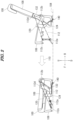
- FIG. 2 is a side view showing a state before the seat back 108 of the seat 100 shown in FIG. 1 is inclined forward and a state after the seat back 108 is inclined forward.
- the right part and the left part of FIG. 2 respectively show the state before the seat back 108 is inclined forward and the state after the seat back 108 is inclined forward.
- a movement mechanism 112 for inclining the seat back 108 forward is a link mechanism that includes four links (bars) shown by the dot-dashed phantom lines.
- the movement mechanism 112 includes four joints 112a, 112b, 112c, and 112d about which the links turn, and the positions of the two joints 112a and 112b do not change in the front-rear direction when the seat back 108 is inclined forward.
- the joint 112c provided on the seat section 106 moves forward and downward as shown in the left part of FIG. 2 .
- the seat section 106 moves forward and downward.
- FIG. 3 is a perspective view and an enlarged partial view of the seat 100 shown in FIG. 1 .
- a recessed portion 114 that is recessed in the vehicle width direction is formed in a lateral side of the seat section 106.
- the recessed portion 114 is made of resin and fitted in the seat section 106.
- a buckle 120 is inserted into the recessed portion 114. Note that illustration of the buckle 120 is omitted in the enlarged partial view shown in the right part of FIG. 3 for the sake of convenience of illustration of the recessed portion 114.
- the buckle 120 is a device to which a tongue (not shown) of a seat belt for an occupant is attached to restrict the occupant with the seat belt.
- the buckle 120 is inserted into the recessed portion 114 provided in the lateral side of the seat section 106 as shown in FIG. 3 , and therefore, when the seat section 106 moves forward and downward as shown in FIG. 2 , the buckle 120 also moves forward and downward.
- FIG. 4 is a perspective view and an enlarged partial view of the seat 100 in the state where the seat section 106 has moved forward and downward as shown in the left part of FIG. 2 .
- FIG. 4 shows the seat 100 covered with the seat cover 109 formed from leather or cloth. That is to say, the seat section 106 and the seat back 108 are covered with the seat cover 109.
- the seat section 106 including the recessed portion 114 provided in the lateral side of the seat section 106 is covered with the seat cover 109.
- a wire harness 122 which is a cord-shaped structure, is routed from the buckle 120 toward the floor panel 104.
- the wire harness 122 is a signal transmission wire for transmitting signals to be used to detect whether or not the seat belt is worn.
- the wire harness may also be a power transmission wire for supplying power to an electric lock mechanism that automatically locks the tongue attached to the buckle 120, for example.
- cord-shaped structure such as the wire harness 122
- the present embodiment may also be applied to a tubular member such as a fluid path member (tube) for sending a fluid (air or air-conditioned air) to the seat section 106, for example, or a string member.
- a tubular member such as a fluid path member (tube) for sending a fluid (air or air-conditioned air) to the seat section 106, for example, or a string member.
- a guide member 124 extends beside the wire harness 122 from the buckle 120 to the floor panel 104.
- the guide member 124 is a flexible member guiding the route of the wire harness 122.
- the guide member 124 is a belt-shaped member that is wider than the wire harness.
- FIG. 5 is a cross-sectional view of the seat 100 taken along the line A-A in FIG. 4 .
- the buckle 120, the wire harness 122, and the guide member 124 are bound together with a binding member 126 that surrounds and covers these three elements.
- the buckle 120 bound with the binding member 126 described above is restricted by a flexible belt-shaped restriction member 130 covering the buckle 120 in the front-rear direction.
- the restriction member 130 is fixed to a lateral side of a seat cushion in front of and behind the buckle 120. More specifically, the restriction member 130 is actually fixed to the seat cover 109 (see FIG. 4 , not shown in FIG. 5 ) formed from leather or the like and covering the seat section 106. With this configuration, the restriction member 130 restricts the buckle 120 to the lateral side of the seat section 106.
- the buckle 120 moves forward and downward when the seat section 106 moves forward and downward as shown in FIG. 2 .
- the wire harness 122 may be pulled in an unexpected direction, and may come into contact with nearby members and be damaged or deteriorate. Therefore, in order to more reliably protect the wire harness 122, the buckle 120 is restricted by the restriction member 130 in the present embodiment so as not to move from the predetermined position on the lateral side of the seat section 106.
- the buckle 120 is inserted into the recessed portion 114 and restricted by the restriction member 130 as shown in FIGS. 4 and 5 .
- displacement of the buckle 120 in the front-rear direction can be restricted more reliably by the recessed portion 114.
- the buckle 120 can be reliably restricted to the lateral side of the seat section 106 by the restriction member 130, it is not essential to provide the recessed portion 114. To the contrary, as long as the recessed portion 114 can reliably hold the buckle 120 on the lateral side of the seat section 106, it is not essential to provide the restriction member 130.
- the buckle 120 is accommodated in the recessed portion 114 in such a manner as not to protrude from the lateral side of the seat section 106 in the vehicle width direction.
- the space in the recessed portion 114 for housing the buckle 120 may have a depth that is smaller than the thickness of the buckle 120 in the vehicle width direction so that the buckle 120 protrudes from the lateral side of the seat section 106 in the vehicle width direction.
- the buckle 120 may be pressed with the restriction member 130 to elastically deform wall surfaces forming the recessed portion 114 and house the buckle 120 in the recessed portion 114.
- FIG. 6 is a perspective view showing an internal structure of the seat 100 shown in FIG. 3 .
- FIG. 6(a) shows an external appearance of the seat 100
- FIG. 6(b) shows the internal structure of the seat 100 in a state where a seat cushion 106A and a seat back cushion 108A are respectively removed from the seat section 106 and the seat back 108 shown in FIG. 6(a)
- FIG. 6(c) shows the internal structure in a state where a frame cover 132 shown in FIG. 6(b) is further removed.
- the seat section 106 includes the seat cushion 106A, which is covered with the seat cover 109 (see FIG. 4 , not shown in FIG. 6 ), and a seat section pipe 136 supporting the seat cushion 106A.
- the seat back 108 includes the seat back cushion 108A, which is covered with the seat cover 109, and a seat back pipe 108B supporting the seat back cushion 108A.
- the frame cover 132 covers a seat section frame 134 extending from the seat back 108 to the seat section 106.
- the seat section frame 134 covers the seat section pipe 136, and both the seat section frame 134 and the seat section pipe 136 are frame members constituting the seat 100.
- a lower portion of the seat section frame 134 is jointed to the seat section pipe 136, and an upper portion of the seat section frame 134 is supported in a turnable manner by the seat back pipe 108B.
- the seat section frame 134 constitutes the joint 112b included in the movement mechanism 112.
- the frame cover 132 and the seat section frame 134 are located in the lower half of the recessed portion 114 and recessed toward the right side of the vehicle from the lateral side of the seat section 106, but are not recessed toward the right side as much as the recessed portion 114.
- the seat frame members constituting the seat section 106 i.e., the seat section frame 134 and the seat section pipe 136 are disposed under the buckle 120.
- the buckle 120 can be supported by the rigid seat section frame 134 and seat section pipe 136 (seat frame members), and displacement of the buckle 120 in the up-down direction can be restricted, and accordingly, displacement of the wire harness 122 can be suppressed.
- the seat section frame 134 and the seat section pipe 136 are recessed toward the right side of the vehicle from the lateral side of the seat section 106 as described above with reference to FIG. 3 . Therefore, a path 138 for the wire harness 122 routed from the buckle 120 is formed between the lateral side of the seat section 106 and the seat section frame 134 and the seat section pipe 136.
- the wire harness 122 can be drawn downward from a lower portion of the buckle 120 as shown in FIG. 5 . Therefore, it is possible to secure the effect of suppressing displacement of the wire harness 122 by restricting displacement of the buckle 120 in the up-down direction with use of the seat section frame 134 and the seat section pipe 136 (seat frame members). Furthermore, it is possible to suppress deterioration of the wire harness 122 by suppressing deformation and displacement of the wire harness 122.
- a portion of the buckle 120 restricted by the restriction member 130 protrudes upward from a seat surface 106B of the seat section 106.
- a predetermined distance a is secured between the buckle 120 and the seat back 108.
- the buckle 120 protrudes upward from the seat surface 106B of the seat section 106, and therefore, the tongue of the seat belt can be easily attached to the buckle 120. Also, downward displacement of the buckle 120 at the time when the seat back 108 is inclined forward is prevented due to the distance ⁇ being secured. Note that it is not essential to secure the distance ⁇ , and the seat back 108 may exactly come into contact with the buckle 120.
- FIG. 7 is a perspective view showing the guide member 124 in the state before the seat section 106 moves forward and downward and the state after the seat section 106 moves forward and downward as shown in FIG. 2 .
- FIG. 7 shows the guide member 124 as viewed from the rear left side of the vehicle.
- FIG. 7 (a) corresponds to the state before the seat section 106 moves forward and downward
- FIG. 7(b) corresponds to the state after the seat section 106 moves forward and downward as shown in FIG. 2
- FIG. 7(c) shows a cross-sectional view of the guide member 124 and the wire harness 122 along the line B-B in FIG. 7(a) .
- the guide member 124 is fixed to the floor panel 104 by a car body fixing member 140.
- the flexible guide member 124 extends beside the wire harness 122 from the buckle 120 to the floor panel 104 as shown in FIG. 7 . Therefore, it is possible to prevent deterioration of the wire harness 122 due to contact with nearby members when the seat section 106 moves.
- a portion 122A of the wire harness 122 other than a portion right under the buckle 120 and a portion extending from the car body fixing member 140 for the guide member 124 extends upward as shown in FIG. 7(a) before the seat section 106 moves forward and downward, but this portion 122A extends almost horizontally as shown in FIG. 7(b) after the movement of the seat section 106.
- a portion 124A of the guide member 124 is adjacent to a lower side of the portion 122A of the wire harness 122 when it extends almost horizontally.
- the guide member 124 is adjacent to the lower side of the portion 122A and prevents deterioration of the wire harness 122 due to contact with the floor panel 104 under the wire harness 122.
- the guide member 124 is a belt-shaped member, and accordingly, easily deforms when the seat section 106 is moved and covers a wide range of the wire harness 122, and therefore has a high effect of protecting the wire harness 122.
- the car body fixing member 140 described above fixes the guide member 124 to the floor panel 104 at a position spaced apart from the buckle 120 to the rear side of the vehicle.
- the guide member 124 is twisted from a position 124B or 124C in such a manner as to have a width arranged along the vehicle width direction while extending from the floor panel 104 to the position 124B or 124C before reaching the buckle 120, and have a width arranged along the vehicle front-rear direction when reaching the buckle 120.
- the position from which the guide member 124 is twisted slightly changes to the position 124B or the position 124C between before and after the seat section 106 moves forward and downward.
- the guide member 124 protects the wire harness 122 from the floor panel 104 by extending beside the lower side of the wire harness 122 particularly when the seat section 106 is moved forward and downward. Therefore, the guide member 124 needs to be positioned in such a manner as to extend horizontally and have its width in the vehicle width direction.
- the guide member 124 needs to be positioned in such a manner as to have its width in the vehicle front-rear direction, i.e., extend in parallel with the lateral side of the seat section 106. Therefore, the guide member 124 needs to be twisted at the position 124B or 124C described above.
- the above-described car body fixing member 140 includes an engaging portion 140A with which the guide member 124 engages.
- the engaging portion 140A is inclined forward and upward from the floor panel 104 toward the buckle 120.
- the engaging portion 140A is inclined as described above, and therefore, the guide member 124 is spaced apart from the floor panel 104 even when the seat section 106 has moved forward and downward as shown in FIG. 7(b) . Accordingly, the wire harness 122 is kept apart from the floor panel 104 and more reliably protected.
- the inclined engaging portion 140A prevents the guide member 124 from sagging by a large amount before and after the movement of the seat section 106 as shown in FIG. 7(a) , and therefore, displacement of the wire harness 122 can be suppressed.
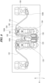
- FIG. 8 is a plan view of the wire harness 122 and the guide member 124 shown in FIG. 7(a) as viewed from above.
- FIG. 9 is a perspective view of the wire harness 122 and the guide member 124 shown in FIG. 8 as viewed from a different direction.
- FIGS. 8 and 9 also show a buckle 150, a wire harness 152, and a guide member 154 for the seat 102 shown in FIG. 1 , but configurations of these are similar to the configurations of the corresponding members for the seat 100, and therefore, descriptions thereof are omitted.
- the wire harness 122 is adjacent to the car body fixing member 140 side, i.e., the rear side in the present embodiment, of the guide member 124 having its width in the vehicle front-rear direction when reaching the buckle 120. This applies not only to the state before the movement of the seat section 106 shown in FIG. 7(a) but also to the state after the movement of the seat section 106 shown in FIG. 7(b) .
- This configuration makes it possible to reduce the length of the wire harness 122 and to avoid an upper portion of the wire harness 122 protected by an upper portion of the guide member 124, which has its width in the vehicle front-rear direction, from coming into contact with nearby members.
- the wire harness 122 is also fixed to the floor panel 104 and pulled rearward by a seat support bracket 160 as shown in FIGS. 8 and 9 , and therefore, the wire harness 122 does not sag to the front side of the guide member 124. Also, the wire harness 122 is spaced apart from the floor panel 104 by the seat support bracket 160 so as not to come into contact with the floor panel 104. The wire harness 122 is also protected with this configuration.
- a support member 162 supporting the seat 102 is fixed to the floor panel 104 via the seat support bracket 160.
- An upper portion of the support member 162 constitutes the joint 112b included in the movement mechanism 112.
- a harness support bracket (cord-shaped structure support bracket) 164 supporting the wire harness 122 is provided on an outer side of the support member 162 and the seat support bracket 160 in the vehicle width direction.
- the wire harness 122 is supported by a front surface of the harness support bracket 164 on the front side of a wire harness supporting position 160A on the seat support bracket 160 as viewed from above.
- the seat support bracket 160 and the harness support bracket 164 suppress displacement of the wire harness 122 on the floor panel 104 side when the seat section 106 is moved forward and downward from its initial position. Also, the wire harness 122 can be kept from coming into contact with components of the vehicle, luggage, or the like disposed behind the seat section 106.
- the wire harness supporting position 160A on the seat support bracket 160 and a supporting position 164A on the harness support bracket 164 are set to be higher than the floor panel 104. Therefore, at least a portion of the wire harness 122 can be spaced apart from the floor panel 104, and sliding contact and other contact between the wire harness 122 and the floor panel 104 can be suppressed.
- the present invention is applicable to a vehicle seat structure.
Landscapes
- Engineering & Computer Science (AREA)
- Mechanical Engineering (AREA)
- Aviation & Aerospace Engineering (AREA)
- Transportation (AREA)
- Seats For Vehicles (AREA)
- Automotive Seat Belt Assembly (AREA)
Abstract
To more reliably protect a cord-shaped structure routed from a buckle provided on a seat section that moves when a seat back is inclined forward, a vehicle seat structure includes: a seat (100) including a seat section (106) and a seat back (108); a movement mechanism (112) for inclining the seat back (108) forward and moving the seat section (106) forward and downward; a buckle (120) that is disposed on a lateral side of the seat section (106) and to which a tongue of a seat belt can be attached; and a wire harness (122) routed from the buckle (120) toward a floor panel (104). The vehicle seat structure further includes a flexible belt-shaped restriction member (130) covering the buckle (120) in a front-rear direction and fixed to the lateral side of the seat section (106) in front of and behind the buckle (120) to restrict the buckle (120) to the lateral side of the seat section (106).
Description
- The present invention relates to a vehicle seat structure.
- A vehicle may be provided with a seat belt reminder function that gives an alarm, for example, to indicate that an occupant seated on a vehicle seat is not wearing a seat belt by using a detection device for detecting whether or not the seat belt in the vehicle is worn.
- In Patent Document 1, for example, the above-described detection is performed by transmitting a signal from a buckle switch installed in a lap-side buckle via a wire harness to an ECU (Electronic Control Unit).
- On the other hand, there is a technology for moving a seat cushion forward and downward when a seat back of a rear seat is inclined forward, in order to secure a wide space behind a front seat.
- [Patent Document 1:
JP 2011-126358A - When a seat cushion configured to move as described above is provided with a buckle to which a cord-shaped structure such as a wire harness for detecting whether or not a seat belt is worn is connected, the following problems occur. That is to say, when the seat cushion moves, the wire harness may come into contact with nearby members and may be damaged or deteriorate.
- Moreover, when the seat cushion moves, the position of the buckle provided on the seat cushion naturally changes, and the buckle may be unexpectedly displaced from its predetermined position on the seat cushion. In such a case as well, the cord-shaped structure such as a wire harness may come into contact with nearby members and be damaged, or the cord-shaped structure may deteriorate due to localized concentration of stress on the cord-shaped structure.
- In view of the above problems, an object of the present invention is to provide a vehicle seat structure that can more reliably protect a cord-shaped structure routed from a buckle provided on a seat cushion that moves forward and downward when a seat back is inclined forward.
- In order to solve the above-described problems, a representative configuration of the present invention is a vehicle seat structure including: a seat including a seat section on which an occupant of a vehicle sits and a seat back arranged upright from a rear portion of the seat section to support the back of the occupant; a movement mechanism for inclining the seat back forward and moving the seat section forward and downward; and a buckle that is disposed on a lateral side of the seat section and to which a tongue of a seat belt for the occupant can be attached, the vehicle seat structure being characterized in further including: a cord-shaped structure routed from the buckle toward a floor panel; and a flexible guide member extending beside the cord-shaped structure from the buckle to the floor panel to guide a route of the cord-shaped structure.
- In order to solve the above-described problems, a representative configuration of the present invention is a vehicle seat structure including: a seat including a seat section on which an occupant of a vehicle sits and a seat back arranged upright from a rear portion of the seat section to support the back of the occupant; a movement mechanism for inclining the seat back forward and moving the seat section forward and downward; a buckle that is disposed on a lateral side of the seat section and to which a tongue of a seat belt for the occupant can be attached; and a cord-shaped structure routed from the buckle toward a floor panel, the vehicle seat structure being characterized in further including a flexible belt-shaped restriction member covering the buckle in a front-rear direction and fixed to the lateral side of the seat section in front of and behind the buckle to restrict the buckle to the lateral side of the seat section.
- According to the present invention, it is possible to provide a vehicle seat structure that can more reliably protect a cord-shaped structure routed from a buckle provided on a seat section that moves forward and downward when a seat back is inclined forward.
-
-
FIG. 1 is a perspective view showing an embodiment of a vehicle seat structure according to the present invention. -
FIG. 2 is a side view showing a state before a seat back of a seat shown inFIG. 1 is inclined forward and a state after the seat back is inclined forward. -
FIG. 3 is a perspective view and an enlarged partial view of the seat shown inFIG. 1 . -
FIG. 4 is a perspective view and an enlarged partial view of the seat in a state where a seat section has moved forward and downward as shown in the left part ofFIG. 2 . -
FIG. 5 is a cross-sectional view of the seat taken along the line A-A inFIG. 4 . -
FIG. 6 is a perspective view showing an internal structure of the seat shown inFIG. 3 . -
FIG. 7 is a perspective view showing a guide member in a state before the seat section moves forward and downward and a state after the seat section moves forward and downward as shown inFIG. 2 . -
FIG. 8 is a plan view showing a wire harness and the guide member shown inFIG. 7(a) as viewed from above. -
FIG. 9 is a perspective view showing the wire harness and the guide member shown inFIG. 8 as viewed from a different direction. - An embodiment of the present invention is a vehicle seat structure including: a seat including a seat section on which an occupant of a vehicle sits and a seat back arranged upright from a rear portion of the seat section to support the back of the occupant; a movement mechanism for inclining the seat back forward and moving the seat section forward and downward; and a buckle that is disposed on a lateral side of the seat section and to which a tongue of a seat belt for the occupant can be attached, the vehicle seat structure being characterized in further including: a cord-shaped structure routed from the buckle toward a floor panel; and a flexible guide member extending beside the cord-shaped structure from the buckle to the floor panel to guide a route of the cord-shaped structure.
- According to the present invention, the flexible guide member extends beside the cord-shaped structure from the buckle to the floor panel, and therefore, the cord-shaped structure can be prevented from coming into contact with nearby members and deteriorating when the seat section is moved.
- It is preferable that, when the seat section is moved forward and downward by the movement mechanism, at least a portion of the guide member is adjacent to a lower side of the cord-shaped structure.
- This configuration can prevent, in particular, deterioration of the cord-shaped structure due to contact with the floor panel under the cord-shaped structure when the seat section is moved forward and downward.
- It is preferable that the guide member is a belt-shaped member that is wider than the cord-shaped structure. A belt-shaped guide member easily deforms when the seat section is moved and covers a wide range of the cord-shaped structure, and therefore has a high effect of protecting the cord-shaped structure.
- It is preferable that the vehicle seat structure further includes a car body fixing member fixing the guide member to the floor panel at a position spaced apart from the buckle in a front-rear direction, and the guide member has a width arranged along a vehicle width direction while extending from the floor panel to a predetermined position before reaching the buckle, is twisted from that position, and has a width arranged along the front-rear direction of the vehicle when reaching the buckle.
- This configuration is adopted because the belt-shaped guide member needs to be twisted at an intermediate position. That is to say, in the vicinity of the floor panel, the guide member needs to be positioned in such a manner as to extend horizontally and have its width in the vehicle width direction in order to protect the cord-shaped structure from the floor panel by extending beside the lower side of the cord-shaped structure particularly when the seat section is moved forward and downward. On the other hand, in order to join the guide member to the buckle, the guide member needs to be positioned in such a manner as to have its width in the vehicle front-rear direction, i.e., extend in parallel with the lateral side of the seat section. Therefore, the guide member needs to be twisted at the predetermined position described above.
- It is preferable that the car body fixing member includes an engaging portion with which the guide member engages, and the engaging portion is inclined from the floor panel toward the buckle.
- In this configuration, the engaging portion is inclined, and therefore, the guide member is spaced apart from the floor panel even when the seat section is moved forward and downward. Accordingly, the cord-shaped structure is kept apart from the floor panel and more reliably protected.
- Moreover, the inclined engaging portion prevents the guide member from sagging by a large amount before and after the movement of the seat section, and therefore, displacement of the cord-shaped structure can be suppressed.
- It is preferable that the cord-shaped structure is adjacent to the car body fixing member side of the guide member having the width in the front-rear direction of the vehicle when reaching the buckle.
- This configuration makes it possible to reduce the length of the cord-shaped structure and to avoid an upper portion of the cord-shaped structure from coming into contact with nearby members.
- Another embodiment of the present invention is a vehicle seat structure including: a seat including a seat section on which an occupant of a vehicle sits and a seat back arranged upright from a rear portion of the seat section to support the back of the occupant; a movement mechanism for inclining the seat back forward and moving the seat section forward and downward; a buckle that is disposed on a lateral side of the seat section and to which a tongue of a seat belt for the occupant can be attached; and a cord-shaped structure routed from the buckle toward a floor panel, the vehicle seat structure being characterized in further including a flexible belt-shaped restriction member covering the buckle in a front-rear direction and fixed to the lateral side of the seat section in front of and behind the buckle to restrict the buckle to the lateral side of the seat section.
- According to the present invention, it is possible to more reliably protect the cord-shaped structure by restricting unexpected displacement of the buckle from a predetermined position on the lateral side of the seat section with use of the restriction member.
- It is preferable that the vehicle seat structure further includes a recessed portion in the lateral side of the seat section, and the buckle is inserted into the recessed portion and restricted by the restriction member. In this configuration, displacement of the buckle can be more reliably restricted by the recessed portion.
- It is preferable that a seat frame member constituting the seat section is disposed under the buckle. In this configuration, the buckle can be supported by the rigid seat frame member, and displacement of the buckle in the up-down direction can be restricted, and accordingly, displacement of the cord-shaped structure can be suppressed.
- It is preferable that the seat frame member is retreated from the lateral side of the seat section to form a path for the cord-shaped structure routed from the buckle between the seat frame member and the lateral side of the seat section.
- In this configuration, the cord-shaped structure can be drawn downward from a lower portion of the buckle, and therefore, it is possible to secure the effect of suppressing displacement of the cord-shaped structure by restricting displacement of the buckle in the up-down direction with use of the seat frame member, and furthermore, it is possible to suppress deterioration of the cord-shaped structure by suppressing deformation and displacement of the cord-shaped structure.
- It is preferable that a portion of the buckle restricted by the restriction member protrudes upward from a seat surface of the seat section, and, when the seat back is inclined forward to the extent possible by the movement mechanism, the seat back comes into contact with the buckle or is spaced apart from the buckle by a predetermined distance.
- In this configuration, the tongue of the seat belt can be easily attached to the protruding buckle, and downward displacement of the buckle at the time when the seat back is inclined forward can be prevented.
- The following describes a preferred embodiment of the present invention in detail with reference to the attached drawings. Dimensions, materials, other specific numerical values, and the like referred to in the embodiment are merely examples for facilitating understanding of the invention, and do not limit the invention unless otherwise stated. In the present specification and the drawings, elements that have substantially the same function and configuration are denoted by the same reference numerals to omit redundant descriptions thereof, and illustration of elements that do not directly relate to the present invention is omitted.
-
FIG. 1 is a perspective view showing an embodiment of a vehicle seat structure according to the present invention. InFIG. 1 and all the other drawings, the front side and the rear side of the vehicle are respectively indicated by arrows F (Forward) and B (Backward), the left side and the right side in the vehicle width direction are respectively indicated by arrows L (Leftward) and R (Rightward), and the upper side and the lower side are respectively indicated by arrows U (Upward) and D (Downward). - As shown in
FIG. 1 , the embodiment of the present invention will be described usingseats FIG. 1 , illustration of seats in the two front rows is omitted. The structures of theseats seat 100 unless otherwise stated. Theseat 100 is placed on afloor panel 104 and includes aseat section 106 on which an occupant of the vehicle sits and a seat back 108 arranged upright from a rear portion of theseat section 106 to support the back of the occupant. - Note that the
seat 100 is actually covered with aseat cover 109 formed from leather or cloth, but illustration of theseat cover 109 is omitted, except inFIG. 4 , which will be described later. -
FIG. 2 is a side view showing a state before the seat back 108 of theseat 100 shown inFIG. 1 is inclined forward and a state after the seat back 108 is inclined forward. As indicated by anarrow 110 inFIG. 2 , the right part and the left part ofFIG. 2 respectively show the state before the seat back 108 is inclined forward and the state after the seat back 108 is inclined forward. Amovement mechanism 112 for inclining the seat back 108 forward is a link mechanism that includes four links (bars) shown by the dot-dashed phantom lines. - The
movement mechanism 112 includes fourjoints joints seat section 106 moves forward and downward as shown in the left part ofFIG. 2 . As described above, when the seat back 108 is inclined forward, theseat section 106 moves forward and downward. -
FIG. 3 is a perspective view and an enlarged partial view of theseat 100 shown inFIG. 1 . As shown in the enlarged partial view, a recessedportion 114 that is recessed in the vehicle width direction is formed in a lateral side of theseat section 106. The recessedportion 114 is made of resin and fitted in theseat section 106. As shown in the left part ofFIG. 3 showing theentire seat 100, abuckle 120 is inserted into the recessedportion 114. Note that illustration of thebuckle 120 is omitted in the enlarged partial view shown in the right part ofFIG. 3 for the sake of convenience of illustration of the recessedportion 114. Thebuckle 120 is a device to which a tongue (not shown) of a seat belt for an occupant is attached to restrict the occupant with the seat belt. - The
buckle 120 is inserted into the recessedportion 114 provided in the lateral side of theseat section 106 as shown inFIG. 3 , and therefore, when theseat section 106 moves forward and downward as shown inFIG. 2 , thebuckle 120 also moves forward and downward. -
FIG. 4 is a perspective view and an enlarged partial view of theseat 100 in the state where theseat section 106 has moved forward and downward as shown in the left part ofFIG. 2 . Unlike the other drawings,FIG. 4 shows theseat 100 covered with theseat cover 109 formed from leather or cloth. That is to say, theseat section 106 and the seat back 108 are covered with theseat cover 109. In particular, theseat section 106 including the recessedportion 114 provided in the lateral side of theseat section 106 is covered with theseat cover 109. - As shown in
FIGS. 2 to 4 , awire harness 122, which is a cord-shaped structure, is routed from thebuckle 120 toward thefloor panel 104. Thewire harness 122 is a signal transmission wire for transmitting signals to be used to detect whether or not the seat belt is worn. However, there is no limitation to such a signal transmission wire, and the wire harness may also be a power transmission wire for supplying power to an electric lock mechanism that automatically locks the tongue attached to thebuckle 120, for example. Moreover, there is no limitation to the cord-shaped structure such as thewire harness 122, and the present embodiment may also be applied to a tubular member such as a fluid path member (tube) for sending a fluid (air or air-conditioned air) to theseat section 106, for example, or a string member. - As shown in
FIGS. 2 to 4 , aguide member 124 extends beside thewire harness 122 from thebuckle 120 to thefloor panel 104. Theguide member 124 is a flexible member guiding the route of thewire harness 122. Theguide member 124 is a belt-shaped member that is wider than the wire harness. -
FIG. 5 is a cross-sectional view of theseat 100 taken along the line A-A inFIG. 4 . As shown inFIGS. 4 and5 , thebuckle 120, thewire harness 122, and theguide member 124 are bound together with a bindingmember 126 that surrounds and covers these three elements. - As shown in
FIGS. 4 and5 , thebuckle 120 bound with the bindingmember 126 described above is restricted by a flexible belt-shapedrestriction member 130 covering thebuckle 120 in the front-rear direction. Therestriction member 130 is fixed to a lateral side of a seat cushion in front of and behind thebuckle 120. More specifically, therestriction member 130 is actually fixed to the seat cover 109 (seeFIG. 4 , not shown inFIG. 5 ) formed from leather or the like and covering theseat section 106. With this configuration, therestriction member 130 restricts thebuckle 120 to the lateral side of theseat section 106. - As already described, the
buckle 120 moves forward and downward when theseat section 106 moves forward and downward as shown inFIG. 2 . However, if thebuckle 120 is unexpectedly displaced from its predetermined position on the lateral side of theseat section 106, thewire harness 122 may be pulled in an unexpected direction, and may come into contact with nearby members and be damaged or deteriorate. Therefore, in order to more reliably protect thewire harness 122, thebuckle 120 is restricted by therestriction member 130 in the present embodiment so as not to move from the predetermined position on the lateral side of theseat section 106. - Also, the
buckle 120 is inserted into the recessedportion 114 and restricted by therestriction member 130 as shown inFIGS. 4 and5 . In the present embodiment, displacement of thebuckle 120 in the front-rear direction can be restricted more reliably by the recessedportion 114. - Note that as long as the
buckle 120 can be reliably restricted to the lateral side of theseat section 106 by therestriction member 130, it is not essential to provide the recessedportion 114. To the contrary, as long as the recessedportion 114 can reliably hold thebuckle 120 on the lateral side of theseat section 106, it is not essential to provide therestriction member 130. - In the present embodiment, the
buckle 120 is accommodated in the recessedportion 114 in such a manner as not to protrude from the lateral side of theseat section 106 in the vehicle width direction. However, the space in the recessedportion 114 for housing thebuckle 120 may have a depth that is smaller than the thickness of thebuckle 120 in the vehicle width direction so that thebuckle 120 protrudes from the lateral side of theseat section 106 in the vehicle width direction. In this case, thebuckle 120 may be pressed with therestriction member 130 to elastically deform wall surfaces forming the recessedportion 114 and house thebuckle 120 in the recessedportion 114. -
FIG. 6 is a perspective view showing an internal structure of theseat 100 shown inFIG. 3 .FIG. 6(a) shows an external appearance of theseat 100,FIG. 6(b) shows the internal structure of theseat 100 in a state where aseat cushion 106A and a seat backcushion 108A are respectively removed from theseat section 106 and the seat back 108 shown inFIG. 6(a), and FIG. 6(c) shows the internal structure in a state where aframe cover 132 shown inFIG. 6(b) is further removed. - The
seat section 106 includes theseat cushion 106A, which is covered with the seat cover 109 (seeFIG. 4 , not shown inFIG. 6 ), and aseat section pipe 136 supporting theseat cushion 106A. The seat back 108 includes the seat backcushion 108A, which is covered with theseat cover 109, and a seat backpipe 108B supporting the seat backcushion 108A. - As shown in
FIGS. 6(b) and 6(c) , theframe cover 132 covers aseat section frame 134 extending from the seat back 108 to theseat section 106. Theseat section frame 134 covers theseat section pipe 136, and both theseat section frame 134 and theseat section pipe 136 are frame members constituting theseat 100. A lower portion of theseat section frame 134 is jointed to theseat section pipe 136, and an upper portion of theseat section frame 134 is supported in a turnable manner by the seat backpipe 108B. With this configuration, theseat section frame 134 constitutes the joint 112b included in themovement mechanism 112. - As shown in
FIG. 3 , theframe cover 132 and theseat section frame 134 are located in the lower half of the recessedportion 114 and recessed toward the right side of the vehicle from the lateral side of theseat section 106, but are not recessed toward the right side as much as the recessedportion 114. - As shown in
FIG. 5 , the seat frame members constituting theseat section 106, i.e., theseat section frame 134 and theseat section pipe 136 are disposed under thebuckle 120. With this configuration, thebuckle 120 can be supported by the rigidseat section frame 134 and seat section pipe 136 (seat frame members), and displacement of thebuckle 120 in the up-down direction can be restricted, and accordingly, displacement of thewire harness 122 can be suppressed. - Moreover, the
seat section frame 134 and the seat section pipe 136 (seat frame members) are recessed toward the right side of the vehicle from the lateral side of theseat section 106 as described above with reference toFIG. 3 . Therefore, apath 138 for thewire harness 122 routed from thebuckle 120 is formed between the lateral side of theseat section 106 and theseat section frame 134 and theseat section pipe 136. - In this configuration, the
wire harness 122 can be drawn downward from a lower portion of thebuckle 120 as shown inFIG. 5 . Therefore, it is possible to secure the effect of suppressing displacement of thewire harness 122 by restricting displacement of thebuckle 120 in the up-down direction with use of theseat section frame 134 and the seat section pipe 136 (seat frame members). Furthermore, it is possible to suppress deterioration of thewire harness 122 by suppressing deformation and displacement of thewire harness 122. - As shown in
FIG. 5 , a portion of thebuckle 120 restricted by therestriction member 130 protrudes upward from aseat surface 106B of theseat section 106. On the other hand, when the seat back 108 is inclined forward to the extent possible by themovement mechanism 112, a predetermined distance a is secured between thebuckle 120 and the seat back 108. - In this configuration, the
buckle 120 protrudes upward from theseat surface 106B of theseat section 106, and therefore, the tongue of the seat belt can be easily attached to thebuckle 120. Also, downward displacement of thebuckle 120 at the time when the seat back 108 is inclined forward is prevented due to the distance α being secured. Note that it is not essential to secure the distance α, and the seat back 108 may exactly come into contact with thebuckle 120. -
FIG. 7 is a perspective view showing theguide member 124 in the state before theseat section 106 moves forward and downward and the state after theseat section 106 moves forward and downward as shown inFIG. 2 . UnlikeFIG. 2 ,FIG. 7 shows theguide member 124 as viewed from the rear left side of the vehicle.FIG. 7 (a) corresponds to the state before theseat section 106 moves forward and downward, andFIG. 7(b) corresponds to the state after theseat section 106 moves forward and downward as shown inFIG. 2 .FIG. 7(c) shows a cross-sectional view of theguide member 124 and thewire harness 122 along the line B-B inFIG. 7(a) . - As shown in
FIG. 7 , theguide member 124 is fixed to thefloor panel 104 by a carbody fixing member 140. - In the present embodiment, the
flexible guide member 124 extends beside thewire harness 122 from thebuckle 120 to thefloor panel 104 as shown inFIG. 7 . Therefore, it is possible to prevent deterioration of thewire harness 122 due to contact with nearby members when theseat section 106 moves. - In particular, a
portion 122A of thewire harness 122 other than a portion right under thebuckle 120 and a portion extending from the carbody fixing member 140 for theguide member 124 extends upward as shown inFIG. 7(a) before theseat section 106 moves forward and downward, but thisportion 122A extends almost horizontally as shown inFIG. 7(b) after the movement of theseat section 106. - A
portion 124A of theguide member 124 is adjacent to a lower side of theportion 122A of thewire harness 122 when it extends almost horizontally. As described above, when theportion 122A of thewire harness 122, whose positional change amount is the largest among the portions of thewire harness 122, comes closest to thefloor panel 104, theguide member 124 is adjacent to the lower side of theportion 122A and prevents deterioration of thewire harness 122 due to contact with thefloor panel 104 under thewire harness 122. - Moreover, the
guide member 124 is a belt-shaped member, and accordingly, easily deforms when theseat section 106 is moved and covers a wide range of thewire harness 122, and therefore has a high effect of protecting thewire harness 122. - As shown in
FIGS. 2 and7 , the carbody fixing member 140 described above fixes theguide member 124 to thefloor panel 104 at a position spaced apart from thebuckle 120 to the rear side of the vehicle. Theguide member 124 is twisted from aposition floor panel 104 to theposition buckle 120, and have a width arranged along the vehicle front-rear direction when reaching thebuckle 120. The position from which theguide member 124 is twisted slightly changes to theposition 124B or theposition 124C between before and after theseat section 106 moves forward and downward. - The configuration in which the belt-shaped guide member is twisted as described above is adopted because the guide member needs to be twisted for the following reason. In the vicinity of the
floor panel 104, theguide member 124 protects thewire harness 122 from thefloor panel 104 by extending beside the lower side of thewire harness 122 particularly when theseat section 106 is moved forward and downward. Therefore, theguide member 124 needs to be positioned in such a manner as to extend horizontally and have its width in the vehicle width direction. On the other hand, in order to join theguide member 124 to thebuckle 120, theguide member 124 needs to be positioned in such a manner as to have its width in the vehicle front-rear direction, i.e., extend in parallel with the lateral side of theseat section 106. Therefore, theguide member 124 needs to be twisted at theposition - As shown in
FIG. 7 , the above-described carbody fixing member 140 includes an engagingportion 140A with which theguide member 124 engages. The engagingportion 140A is inclined forward and upward from thefloor panel 104 toward thebuckle 120. - The engaging
portion 140A is inclined as described above, and therefore, theguide member 124 is spaced apart from thefloor panel 104 even when theseat section 106 has moved forward and downward as shown inFIG. 7(b) . Accordingly, thewire harness 122 is kept apart from thefloor panel 104 and more reliably protected. - Also, the inclined engaging
portion 140A prevents theguide member 124 from sagging by a large amount before and after the movement of theseat section 106 as shown inFIG. 7(a) , and therefore, displacement of thewire harness 122 can be suppressed. -
FIG. 8 is a plan view of thewire harness 122 and theguide member 124 shown inFIG. 7(a) as viewed from above.FIG. 9 is a perspective view of thewire harness 122 and theguide member 124 shown inFIG. 8 as viewed from a different direction.FIGS. 8 and9 also show abuckle 150, awire harness 152, and aguide member 154 for theseat 102 shown inFIG. 1 , but configurations of these are similar to the configurations of the corresponding members for theseat 100, and therefore, descriptions thereof are omitted. - As shown in
FIG. 7(c) , thewire harness 122 is adjacent to the carbody fixing member 140 side, i.e., the rear side in the present embodiment, of theguide member 124 having its width in the vehicle front-rear direction when reaching thebuckle 120. This applies not only to the state before the movement of theseat section 106 shown inFIG. 7(a) but also to the state after the movement of theseat section 106 shown inFIG. 7(b) . - This configuration makes it possible to reduce the length of the
wire harness 122 and to avoid an upper portion of thewire harness 122 protected by an upper portion of theguide member 124, which has its width in the vehicle front-rear direction, from coming into contact with nearby members. - Note that the
wire harness 122 is also fixed to thefloor panel 104 and pulled rearward by aseat support bracket 160 as shown inFIGS. 8 and9 , and therefore, thewire harness 122 does not sag to the front side of theguide member 124. Also, thewire harness 122 is spaced apart from thefloor panel 104 by theseat support bracket 160 so as not to come into contact with thefloor panel 104. Thewire harness 122 is also protected with this configuration. - As shown in
FIGS. 8 and9 , asupport member 162 supporting theseat 102 is fixed to thefloor panel 104 via theseat support bracket 160. An upper portion of thesupport member 162 constitutes the joint 112b included in themovement mechanism 112. - A harness support bracket (cord-shaped structure support bracket) 164 supporting the
wire harness 122 is provided on an outer side of thesupport member 162 and theseat support bracket 160 in the vehicle width direction. - As shown in
FIG. 8 , thewire harness 122 is supported by a front surface of theharness support bracket 164 on the front side of a wireharness supporting position 160A on theseat support bracket 160 as viewed from above. - In this configuration, the
seat support bracket 160 and theharness support bracket 164 suppress displacement of thewire harness 122 on thefloor panel 104 side when theseat section 106 is moved forward and downward from its initial position. Also, thewire harness 122 can be kept from coming into contact with components of the vehicle, luggage, or the like disposed behind theseat section 106. - Furthermore, the wire
harness supporting position 160A on theseat support bracket 160 and a supportingposition 164A on theharness support bracket 164 are set to be higher than thefloor panel 104. Therefore, at least a portion of thewire harness 122 can be spaced apart from thefloor panel 104, and sliding contact and other contact between thewire harness 122 and thefloor panel 104 can be suppressed. - Although a preferred embodiment of the present invention has been described with reference to the attached drawings, it goes without saying that the present invention is not limited to this example. It is clear that those skilled in the art will be able to arrive at various changes and modifications within the scope of the claims, and those changes and modifications are understood to naturally fall within the technical scope of the present invention.
- Also, it is possible to embody the present invention by freely combining inventions described in the claims and in the Example, irrespective of the dependency of the claims.
- The present invention is applicable to a vehicle seat structure.
- 100, 102 ... seat; 104 ... floor panel; 106 ... seat section; 106A... seat cushion; 106B ... seat surface; 108 ... seat back; 108A ... seat back cushion; 109 ... seat cover; 112 ... movement mechanism; 114 ... recessed portion; 120, 150 ... buckle; 122, 152 ... wire harness; 124, 154 ... guide member; 126 ... binding member; 130 ... restriction member; 132 ... frame cover; 134 ... seat section frame; 136 ... seat section pipe; 140 ... car body fixing member; 140A ... engaging portion; 160 ... seat support bracket; 162 ... support member; 164 ... harness support bracket
Claims (5)
- A vehicle seat structure comprising:a seat (100, 102) that includes a seat section (106) on which an occupant of a vehicle sits and a seat back (108) arranged upright from a rear portion of the seat section (106) to support the back of the occupant;a movement mechanism (112) for inclining the seat back (108) forward and moving the seat section (106) forward and downward;a buckle (120, 150) that is disposed on a lateral side of the seat section (106) and to which a tongue of a seat belt for the occupant can be attached;a cord-shaped structure (122, 152) routed from the buckle (120, 150) toward a floor panel (104); anda flexible belt-shaped restriction member (130) covering the buckle (120, 150) in a front-rear direction and fixed to the lateral side of the seat section (106) in front of and behind the buckle (120, 150) to restrict the buckle (120, 150) to the lateral side of the seat section (106).
- The vehicle seat structure according to claim 1, further comprising:a recessed portion (114) in the lateral side of the seat section (106),wherein the buckle (120, 150) is inserted into the recessed portion (114) and restricted by the restriction member (130).
- The vehicle seat structure according to claim 1 or 2,
wherein a seat frame member (134, 136) constituting the seat section (106) is disposed under the buckle (120, 150). - The vehicle seat structure according to claim 3,
wherein the seat frame member (134, 136) is retreated from the lateral side of the seat section (106) to form a path (138) for the cord-shaped structure (122, 152) routed from the buckle (120, 150) between the seat frame member (134, 136) and the lateral side of the seat section (106). - The vehicle seat structure according to any one of claims 1 to 4,wherein a portion of the buckle (120, 150) restricted by the restriction member (130) protrudes upward from a seat surface (106B) of the seat section (106), andwhen the seat back (108) is inclined forward to the extent possible by the movement mechanism (112), the seat back (108) comes into contact with the buckle (120, 150) or is spaced apart from the buckle (120, 150) by a predetermined distance.
Applications Claiming Priority (1)
| Application Number | Priority Date | Filing Date | Title |
|---|---|---|---|
| JP2023115839A JP2025012759A (en) | 2023-07-14 | 2023-07-14 | Vehicle seat structure |
Publications (1)
| Publication Number | Publication Date |
|---|---|
| EP4491451A1 true EP4491451A1 (en) | 2025-01-15 |
Family
ID=91829047
Family Applications (1)
| Application Number | Title | Priority Date | Filing Date |
|---|---|---|---|
| EP24186562.5A Pending EP4491451A1 (en) | 2023-07-14 | 2024-07-04 | Vehicle seat structure |
Country Status (2)
| Country | Link |
|---|---|
| EP (1) | EP4491451A1 (en) |
| JP (1) | JP2025012759A (en) |
Citations (6)
| Publication number | Priority date | Publication date | Assignee | Title |
|---|---|---|---|---|
| JPS58131850U (en) * | 1982-02-26 | 1983-09-06 | いすゞ自動車株式会社 | vehicle inner seat belt |
| JPS6359059U (en) * | 1986-10-08 | 1988-04-20 | ||
| JPH0424855U (en) * | 1990-06-22 | 1992-02-27 | ||
| JP2004090894A (en) * | 2002-09-04 | 2004-03-25 | Honda Motor Co Ltd | Seat belt holding structure for vehicle seats |
| JP2011126358A (en) | 2009-12-16 | 2011-06-30 | Toyota Motor Corp | Reminder device of seat belt |
| EP2985176A1 (en) * | 2013-04-12 | 2016-02-17 | Honda Motor Co., Ltd. | Vehicular seat device |
-
2023
- 2023-07-14 JP JP2023115839A patent/JP2025012759A/en active Pending
-
2024
- 2024-07-04 EP EP24186562.5A patent/EP4491451A1/en active Pending
Patent Citations (6)
| Publication number | Priority date | Publication date | Assignee | Title |
|---|---|---|---|---|
| JPS58131850U (en) * | 1982-02-26 | 1983-09-06 | いすゞ自動車株式会社 | vehicle inner seat belt |
| JPS6359059U (en) * | 1986-10-08 | 1988-04-20 | ||
| JPH0424855U (en) * | 1990-06-22 | 1992-02-27 | ||
| JP2004090894A (en) * | 2002-09-04 | 2004-03-25 | Honda Motor Co Ltd | Seat belt holding structure for vehicle seats |
| JP2011126358A (en) | 2009-12-16 | 2011-06-30 | Toyota Motor Corp | Reminder device of seat belt |
| EP2985176A1 (en) * | 2013-04-12 | 2016-02-17 | Honda Motor Co., Ltd. | Vehicular seat device |
Also Published As
| Publication number | Publication date |
|---|---|
| JP2025012759A (en) | 2025-01-24 |
Similar Documents
| Publication | Publication Date | Title |
|---|---|---|
| US10507748B2 (en) | Seat for vehicle | |
| EP2692575B1 (en) | Vehicle seat | |
| JP5126481B2 (en) | Split-type seat back opening prevention structure | |
| JP6558442B2 (en) | Seat frame | |
| CN116373707B (en) | Vehicle seats | |
| US8789889B2 (en) | Vehicle buckle support apparatus | |
| CN111516558B (en) | Transportation seats | |
| CN104780812A (en) | Vehicle seat | |
| CN104870253A (en) | Seat device | |
| CN106660470B (en) | mounting structure of vehicle seat | |
| EP4491450A1 (en) | Vehicle seat structure | |
| JP5583086B2 (en) | Power supply device for slide sheet | |
| US7661744B2 (en) | Attaching structure of split type seat back for vehicle | |
| US20150091361A1 (en) | Conveyance seat | |
| CN107009921A (en) | Seat unit and vehicle | |
| EP3811824B1 (en) | Seat | |
| JP6869911B2 (en) | Armrest | |
| JP4222235B2 (en) | Sheet | |
| JP2025012759A (en) | Vehicle seat structure | |
| CN103909839B (en) | Seat for vehicle | |
| JP2014117988A (en) | Structure for arranging harness to floor panel of motor vehicle | |
| JP7705062B2 (en) | Vehicle seats | |
| CN120422730A (en) | Seat for vehicle | |
| CN106042992A (en) | Vehicle seat | |
| JP7260567B2 (en) | vehicle seat structure |
Legal Events
| Date | Code | Title | Description |
|---|---|---|---|
| PUAI | Public reference made under article 153(3) epc to a published international application that has entered the european phase |
Free format text: ORIGINAL CODE: 0009012 |
|
| STAA | Information on the status of an ep patent application or granted ep patent |
Free format text: STATUS: REQUEST FOR EXAMINATION WAS MADE |
|
| 17P | Request for examination filed |
Effective date: 20240704 |
|
| AK | Designated contracting states |
Kind code of ref document: A1 Designated state(s): AL AT BE BG CH CY CZ DE DK EE ES FI FR GB GR HR HU IE IS IT LI LT LU LV MC ME MK MT NL NO PL PT RO RS SE SI SK SM TR |
|
| STAA | Information on the status of an ep patent application or granted ep patent |
Free format text: STATUS: EXAMINATION IS IN PROGRESS |
|
| 17Q | First examination report despatched |
Effective date: 20260324 |