EP4491440A1 - A charging arrangement for supplying electrical energy to an electrical vehicle - Google Patents
A charging arrangement for supplying electrical energy to an electrical vehicle Download PDFInfo
- Publication number
- EP4491440A1 EP4491440A1 EP23184562.9A EP23184562A EP4491440A1 EP 4491440 A1 EP4491440 A1 EP 4491440A1 EP 23184562 A EP23184562 A EP 23184562A EP 4491440 A1 EP4491440 A1 EP 4491440A1
- Authority
- EP
- European Patent Office
- Prior art keywords
- charging
- arm
- cable
- arrangement according
- supplying
- Prior art date
- Legal status (The legal status is an assumption and is not a legal conclusion. Google has not performed a legal analysis and makes no representation as to the accuracy of the status listed.)
- Withdrawn
Links
Images


Classifications
-
- B—PERFORMING OPERATIONS; TRANSPORTING
- B60—VEHICLES IN GENERAL
- B60L—PROPULSION OF ELECTRICALLY-PROPELLED VEHICLES; SUPPLYING ELECTRIC POWER FOR AUXILIARY EQUIPMENT OF ELECTRICALLY-PROPELLED VEHICLES; ELECTRODYNAMIC BRAKE SYSTEMS FOR VEHICLES IN GENERAL; MAGNETIC SUSPENSION OR LEVITATION FOR VEHICLES; MONITORING OPERATING VARIABLES OF ELECTRICALLY-PROPELLED VEHICLES; ELECTRIC SAFETY DEVICES FOR ELECTRICALLY-PROPELLED VEHICLES
- B60L53/00—Methods of charging batteries, specially adapted for electric vehicles; Charging stations or on-board charging equipment therefor; Exchange of energy storage elements in electric vehicles
- B60L53/10—Methods of charging batteries, specially adapted for electric vehicles; Charging stations or on-board charging equipment therefor; Exchange of energy storage elements in electric vehicles characterised by the energy transfer between the charging station and the vehicle
- B60L53/14—Conductive energy transfer
- B60L53/18—Cables specially adapted for charging electric vehicles
-
- B—PERFORMING OPERATIONS; TRANSPORTING
- B60—VEHICLES IN GENERAL
- B60L—PROPULSION OF ELECTRICALLY-PROPELLED VEHICLES; SUPPLYING ELECTRIC POWER FOR AUXILIARY EQUIPMENT OF ELECTRICALLY-PROPELLED VEHICLES; ELECTRODYNAMIC BRAKE SYSTEMS FOR VEHICLES IN GENERAL; MAGNETIC SUSPENSION OR LEVITATION FOR VEHICLES; MONITORING OPERATING VARIABLES OF ELECTRICALLY-PROPELLED VEHICLES; ELECTRIC SAFETY DEVICES FOR ELECTRICALLY-PROPELLED VEHICLES
- B60L53/00—Methods of charging batteries, specially adapted for electric vehicles; Charging stations or on-board charging equipment therefor; Exchange of energy storage elements in electric vehicles
- B60L53/10—Methods of charging batteries, specially adapted for electric vehicles; Charging stations or on-board charging equipment therefor; Exchange of energy storage elements in electric vehicles characterised by the energy transfer between the charging station and the vehicle
- B60L53/11—DC charging controlled by the charging station, e.g. mode 4
-
- B—PERFORMING OPERATIONS; TRANSPORTING
- B60—VEHICLES IN GENERAL
- B60L—PROPULSION OF ELECTRICALLY-PROPELLED VEHICLES; SUPPLYING ELECTRIC POWER FOR AUXILIARY EQUIPMENT OF ELECTRICALLY-PROPELLED VEHICLES; ELECTRODYNAMIC BRAKE SYSTEMS FOR VEHICLES IN GENERAL; MAGNETIC SUSPENSION OR LEVITATION FOR VEHICLES; MONITORING OPERATING VARIABLES OF ELECTRICALLY-PROPELLED VEHICLES; ELECTRIC SAFETY DEVICES FOR ELECTRICALLY-PROPELLED VEHICLES
- B60L53/00—Methods of charging batteries, specially adapted for electric vehicles; Charging stations or on-board charging equipment therefor; Exchange of energy storage elements in electric vehicles
- B60L53/10—Methods of charging batteries, specially adapted for electric vehicles; Charging stations or on-board charging equipment therefor; Exchange of energy storage elements in electric vehicles characterised by the energy transfer between the charging station and the vehicle
- B60L53/14—Conductive energy transfer
- B60L53/16—Connectors, e.g. plugs or sockets, specially adapted for charging electric vehicles
-
- B—PERFORMING OPERATIONS; TRANSPORTING
- B60—VEHICLES IN GENERAL
- B60L—PROPULSION OF ELECTRICALLY-PROPELLED VEHICLES; SUPPLYING ELECTRIC POWER FOR AUXILIARY EQUIPMENT OF ELECTRICALLY-PROPELLED VEHICLES; ELECTRODYNAMIC BRAKE SYSTEMS FOR VEHICLES IN GENERAL; MAGNETIC SUSPENSION OR LEVITATION FOR VEHICLES; MONITORING OPERATING VARIABLES OF ELECTRICALLY-PROPELLED VEHICLES; ELECTRIC SAFETY DEVICES FOR ELECTRICALLY-PROPELLED VEHICLES
- B60L53/00—Methods of charging batteries, specially adapted for electric vehicles; Charging stations or on-board charging equipment therefor; Exchange of energy storage elements in electric vehicles
- B60L53/30—Constructional details of charging stations
- B60L53/302—Cooling of charging equipment
-
- B—PERFORMING OPERATIONS; TRANSPORTING
- B60—VEHICLES IN GENERAL
- B60L—PROPULSION OF ELECTRICALLY-PROPELLED VEHICLES; SUPPLYING ELECTRIC POWER FOR AUXILIARY EQUIPMENT OF ELECTRICALLY-PROPELLED VEHICLES; ELECTRODYNAMIC BRAKE SYSTEMS FOR VEHICLES IN GENERAL; MAGNETIC SUSPENSION OR LEVITATION FOR VEHICLES; MONITORING OPERATING VARIABLES OF ELECTRICALLY-PROPELLED VEHICLES; ELECTRIC SAFETY DEVICES FOR ELECTRICALLY-PROPELLED VEHICLES
- B60L53/00—Methods of charging batteries, specially adapted for electric vehicles; Charging stations or on-board charging equipment therefor; Exchange of energy storage elements in electric vehicles
- B60L53/30—Constructional details of charging stations
- B60L53/35—Means for automatic or assisted adjustment of the relative position of charging devices and vehicles
-
- Y—GENERAL TAGGING OF NEW TECHNOLOGICAL DEVELOPMENTS; GENERAL TAGGING OF CROSS-SECTIONAL TECHNOLOGIES SPANNING OVER SEVERAL SECTIONS OF THE IPC; TECHNICAL SUBJECTS COVERED BY FORMER USPC CROSS-REFERENCE ART COLLECTIONS [XRACs] AND DIGESTS
- Y02—TECHNOLOGIES OR APPLICATIONS FOR MITIGATION OR ADAPTATION AGAINST CLIMATE CHANGE
- Y02T—CLIMATE CHANGE MITIGATION TECHNOLOGIES RELATED TO TRANSPORTATION
- Y02T10/00—Road transport of goods or passengers
- Y02T10/60—Other road transportation technologies with climate change mitigation effect
- Y02T10/70—Energy storage systems for electromobility, e.g. batteries
-
- Y—GENERAL TAGGING OF NEW TECHNOLOGICAL DEVELOPMENTS; GENERAL TAGGING OF CROSS-SECTIONAL TECHNOLOGIES SPANNING OVER SEVERAL SECTIONS OF THE IPC; TECHNICAL SUBJECTS COVERED BY FORMER USPC CROSS-REFERENCE ART COLLECTIONS [XRACs] AND DIGESTS
- Y02—TECHNOLOGIES OR APPLICATIONS FOR MITIGATION OR ADAPTATION AGAINST CLIMATE CHANGE
- Y02T—CLIMATE CHANGE MITIGATION TECHNOLOGIES RELATED TO TRANSPORTATION
- Y02T10/00—Road transport of goods or passengers
- Y02T10/60—Other road transportation technologies with climate change mitigation effect
- Y02T10/7072—Electromobility specific charging systems or methods for batteries, ultracapacitors, supercapacitors or double-layer capacitors
-
- Y—GENERAL TAGGING OF NEW TECHNOLOGICAL DEVELOPMENTS; GENERAL TAGGING OF CROSS-SECTIONAL TECHNOLOGIES SPANNING OVER SEVERAL SECTIONS OF THE IPC; TECHNICAL SUBJECTS COVERED BY FORMER USPC CROSS-REFERENCE ART COLLECTIONS [XRACs] AND DIGESTS
- Y02—TECHNOLOGIES OR APPLICATIONS FOR MITIGATION OR ADAPTATION AGAINST CLIMATE CHANGE
- Y02T—CLIMATE CHANGE MITIGATION TECHNOLOGIES RELATED TO TRANSPORTATION
- Y02T90/00—Enabling technologies or technologies with a potential or indirect contribution to GHG emissions mitigation
- Y02T90/10—Technologies relating to charging of electric vehicles
- Y02T90/12—Electric charging stations
-
- Y—GENERAL TAGGING OF NEW TECHNOLOGICAL DEVELOPMENTS; GENERAL TAGGING OF CROSS-SECTIONAL TECHNOLOGIES SPANNING OVER SEVERAL SECTIONS OF THE IPC; TECHNICAL SUBJECTS COVERED BY FORMER USPC CROSS-REFERENCE ART COLLECTIONS [XRACs] AND DIGESTS
- Y02—TECHNOLOGIES OR APPLICATIONS FOR MITIGATION OR ADAPTATION AGAINST CLIMATE CHANGE
- Y02T—CLIMATE CHANGE MITIGATION TECHNOLOGIES RELATED TO TRANSPORTATION
- Y02T90/00—Enabling technologies or technologies with a potential or indirect contribution to GHG emissions mitigation
- Y02T90/10—Technologies relating to charging of electric vehicles
- Y02T90/14—Plug-in electric vehicles
Definitions
- the present invention relates to a charging arrangement for supplying electrical energy to an electrical vehicle, in particular an electrical car, an electrical bus, an electrical truck or a formula E vehicle.
- a robotic charging station for charging a battery of an electric vehicle including a base plate, a riser coupled with the base plate and extending substantially transverse to the base plate, and a robotic arm.
- the robotic arm extends from the riser and supports an end effector.
- the end effector includes a plurality of electrical contacts configured to couple with a receptacle disposed on the electric vehicle.
- the robotic arm is configured to move the end effector in three degrees of motion.
- a charging device for autonomously charging an electric vehicle.
- Said charging device comprises a main body, which is controllably moveable in at least one of a rotational, vertical, or lateral direction; an arm coupled to the main body, which is controllably extendable and retractable in a longitudinal direction and a charging plug at a distal end of the arm.
- the arm can have a form of a rigid chain and the charging plug is configured to be controllably moveable and insertable into a charging portal of the electric vehicle.
- the charging system comprises a charging arm having a vertical charging arm part and a horizontal charging arm part. Further, charging system comprises a charging cable or a bus bar, which can be connected to the electric vehicle to be charged.
- the horizontal charging arm part having a deployable rigid chain, using which a vehicle-side end of the charging cable or the bus bar can be moved towards the electric vehicle.
- Japanese patent application JP2011163045A discloses a garage for charging an electric vehicle with electric power from an external power source.
- the garage includes a parking space for the electric vehicle, a pair of pillars arranged at both ends of at least one side of the electric vehicle in the front-rear direction in the parking space, a frame arranged to connect between the pair of pillars, a charger for supplying electric power to a battery of the electric vehicle.
- the frame includes a busbar connected with the charger by a cable.
- the busbar may be configured to be connected to a household outlet instead of charger.
- the busbar is further connected to a power supply arm having a cable and a charging connector. Said cable is wound around a reel drum provided in the power supply arm.
- European patent application EP3708412A1 discloses a force assisted charging arrangement for supplying electrical energy to an electrical vehicle.
- the force assisted charging arrangement comprises a first set of bus bars, a second set of bus bars, a charging cable and charging connector.
- the first set of bus bars is arranged distant and fixed in respect to ground.
- a first end of the second set of bus bars is connected rotatable to the first set of bus bars thereby allowing a rotation of its second end around a vertical rotation axis.
- a first end of the charging cable is connected to a charging connector and a second end of the charging cable is connected to a second end of the second set of bus bars.
- the charging cable and charging connector are cooled with the usage of liquid.
- the use of charging arrangements for supplying electrical energy to an electrical vehicle is associated with the problem of heating charging cables and/or charging plugs, which require cooling using dedicated cooling devices.
- the heating of charging cables is usually caused by their long lengths. To prevent this, their cross sections are increased, which increases their weight and imposes the need to use cooling devices of large sizes and high powers, which generate high noise levels. Increased cable weight and high noise levels significantly reduce the comfort of using of said arrangements.
- the object of the invention is to provide a charging arrangement for supplying electrical energy to an electrical vehicle that provides possibility of use of cooling devices of smaller powers, efficiency and sizes that are quieter than commonly used cooling devices.
- the object of the invention is a charging arrangement for supplying electrical energy to an electrical vehicle comprising a charging arm, and a charging cable, wherein a first end of the charging arm is connected to a first end of the charging cable and a second end of the charging cable is equipped with a charging plug, wherein the charging cable and/or the charging plug is liquid-cooled, and wherein the charging arm comprises at least two busbars for supplying DC current to an electrical vehicle and a protective earth busbar for protecting against electric shocks.
- the charging arrangement comprises further a charging unit, and a second end of the charging arm is rotatably connected to the charging unit thereby allowing a movement of the first end of the charging arm relative to a vertical rotation axis (x).
- the application of the charging unit and the rotatory connection of the second end of the charging arm and the charging unit allowing a movement of the first end of the charging arm relative to a vertical rotation axis (x) provides possibility of use of cooling devices of smaller powers, efficiency and sizes that are quieter than commonly used cooling devices. It also leads to reduction in the amount of liquid used for such cooling. Consequently, it leads to increase of the comfort of use of such charging arrangements. This is due to the fact that said application of the charging unit and the rotatory connection of the second end of the charging arm and the charging unit in the charging arrangement ensures shortening of the charging cable and reduction of power losses over a path of an electric current transmission compared to the solution known from the state of the art. That, a as a consequence, leads to reduction in heating of the charging cable.
- liquid-cooled charging cable and/or the charging plug ensures a reduction of charging times of an electric vehicle.
- the charging arrangement comprises communication and signal wires that run through the charging arm and the charging cable and are connected to the charging plug.
- the application of the communication and signal wires that run through the charging arm and the charging cable and are connected to the charging plug ensures automatic start of a charging process of an electrical vehicle, its control and termination.
- the charging cable and/or the charging plug is liquid-cooled with the use of cooling conduits.
- the busbars are made of copper or aluminum.
- the busbars of the charging arm are isolated.
- the busbars for supplying DC currents are dimensioned for supplying DC currents up to 3000A at a DC voltage of 1500V.
- the charging arm extends in a horizontal direction.
- the application of the charging arm that extends in a horizontal direction eliminates the need of a user of the disclosed charging arrangement to lift the charging cable from the ground to connect said charging cable to a charging input of an electrical vehicle. This completely prevents the user from lifting and carrying such cable.
- the application of the charging arm that extends in a horizontal direction prevents the charging plug from hitting the ground and as a result prevents from mechanical damage to the charging plug.
- the charging arrangement according to the invention is more reliable compared to the solutions known from the prior art.
- the range of the movement of the first end of the charging arm relative to the vertical rotation axis (x) is up to 300°.
- the range of the movement of the first end of the charging arm relative to the vertical rotation axis (x) is 270°.
- the application of the range of the movement of the first end of the charging arm relative to the vertical rotation axis (x) of up to 300°, in particular of 270°, ensures easy movement of the charging cable to a charging position of an electrical vehicle as the charging cable, together with the charging arm, moves relative to the charging unit. This ensures the capability to support several charging positions, in particular, from 2 to 4 charging positions.
- the charging arm and the charging unit are connected by a rotary joint.
- the rotary joint is fixed to the top of the charging unit.
- connection of the first end of the charging arm with the first end of the charging cable is watertight and dustproof connection.
- the watertight and dustproof connection is made with the use of a cable gland.
- the charging unit is configured for connecting to an AC grid, a DC grid or a DC power supply.
- the object of the invention is also a charging station comprising at least one charging arrangement as above-disclosed.
- the charging arrangement according to the invention makes it possible to transmit DC currents of large values without generating large voltage drops, and therefore without generating large power losses while simplifying a construction of the charging arrangement. It constitutes a consequence of the application of a charging unit and a rotatory connection of a second end of the charging arm and the charging unit.
- the charging arrangement according to the invention ensures a reduction of power losses compared to the solutions known from the prior art.
- the charging arrangement according to the invention increases further the comfort of its use, as a user of the disclosed charging arrangement no longer has to lift and carry charging cables characterized by high weight due to their large cross-sections.
- the charging arrangement according to the invention provides higher flexibility of its usage compared to the solutions known from the prior art as a charging arm and a charging cable connected to it have a large range of movement due to a rotary connection of said arm and a charging unit.
- the charging arrangement according to the invention is ergonomic as the arrangement is designed such that a charging cable hangs down from a charging arm.
- the charging arrangement according to the invention eliminates the need to use a cable retraction system.
- a charging arrangement for supplying electrical energy to an electrical vehicle
- a charging arrangement 1 for supplying electrical energy to an electrical vehicle comprises a charging arm 2 and a charging cable 3.
- a first end of the charging arm 2 is connected to a first end of the charging cable 3 and a second end of the charging cable 3 is equipped with a charging plug 4.
- the connection of the first end of the charging arm 2 with the first end of the charging cable 3 is watertight and dustproof connection.
- the watertight and dustproof connection is made with the use of a cable gland 10.
- the charging cable 3 and the charging plug 4 are liquid-cooled with the use of cooling conduits 9.
- the cooling conduits 9 have a form of pipes made of a thermally conductive material and cooling liquid is for example an oil-based liquid.
- the application of the liquid-cooled charging cable 3 and the charging plug 4, in particular with the use of cooling conduits 9, ensures a reduction of charging times of an electric vehicle.
- the charging arm 2 comprises busbars 5 for supplying DC currents to an electrical vehicle and a protective earth busbar 6 for protecting against electric shocks.
- the busbars 5 for supplying DC currents can be dimensioned for supplying DC currents of 1500A at a DC voltage of 1500V. In such case, the cross-section of said busbars 5 is 1000 mm 2 (100 x 10 mm).
- the charging arrangement 1 comprises communication and signal wires 8 that run through the charging arm 2 and the charging cable 3 and are connected to the charging plug 4. The application of the communication and signal wires 8 that run through the charging arm 2 and the charging cable 3 and are connected to the charging plug 4 ensures automatic start of a charging process of an electrical vehicle, its control and termination.
- the busbars 5, 6 are made of copper.
- the busbars 5, 6 are made of aluminum.
- the busbars 5 for supplying DC currents to an electrical vehicle are isolated from each other. Further, said busbars 5 are isolated from the protective earth busbar 6 as well as the communication and signal wires 8.
- the charging arm 2 extends in a horizontal direction.
- the application of the charging arm 2 that extends in a horizontal direction eliminates the need of a user of the disclosed charging arrangement 1 to lift the charging cable 3 from the ground to connect said charging cable 3 to a charging input of an electrical vehicle. This completely prevents the user from lifting and carrying such cable. Further, the application of the charging arm 2 that extends in a horizontal direction prevents the charging plug 4 from hitting the ground and as a result prevents from mechanical damage to the charging plug 4.
- the charging arrangement 1 according to the invention is more reliable compared to the solutions known from the prior art.
- the charging arrangement 1 comprises further a charging unit 7 and a second end of the charging arm 2 is rotatably connected to the charging unit 7 thereby allowing a movement of the first end of the charging arm 2 relative to a vertical rotation axis (x).
- the application of the charging unit 7 and the rotatory connection of the second end of the charging arm 2 and the charging unit 7 allowing a movement of the first end of the charging arm 2 relative to a vertical rotation axis (x) provides possibility of use of cooling devices of smaller powers, efficiency and sizes that are quieter than commonly used cooling devices. It also leads to reduction in the amount of liquid used for such cooling. Consequently, it leads to increase of the comfort of use of such charging arrangements.
- This is due to the fact that said application of the charging unit 7 and the rotatory connection of the second end of the charging arm 2 and the charging unit 7 in the charging arrangement 1 ensures shortening of the charging cable 3 and reduction of power losses over a path of an electric current transmission compared to the solution known from the state of the art. That, a as a consequence, leads to reduction in heating of the charging cable 3.
- the range of the movement of the first end of the charging arm 2 relative to the vertical rotation axis (x) is up to 300°, in particular 270°.
- the application of the range of the movement of the first end of the charging arm 2 relative to the vertical rotation axis (x) of up to 300°, in particular of 270°, ensures easy movement of the charging cable 3 to a charging position of an electrical vehicle as the charging cable 3, together with the charging arm 2, moves relative to the charging unit 7. This ensures the capability to support several charging positions, in particular, from 2 to 4 charging positions.
- the charging unit 7 is configured for connecting to an AC grid.
- the charging unit 5 can be connected via a transformer and a converter to an AC grid.
- the charging unit 7 can be configured for connecting to a DC grid.
- the charging unit 7 can be configured for connecting to a DC power supply.
- the charging arm 2 and the charging unit 7 are connected by a rotary joint 10.
- the rotary joint 10 is fixed to the top of the charging unit 7.
- the application of the rotary joint 10 to connect the charging arm 2 and the charging unit 7 provides a simple and safe connection of the aforementioned elements.
- a charging station 12 comprising charging arrangements 1 as above-disclosed.
Landscapes
- Engineering & Computer Science (AREA)
- Power Engineering (AREA)
- Transportation (AREA)
- Mechanical Engineering (AREA)
- Charge And Discharge Circuits For Batteries Or The Like (AREA)
- Electric Propulsion And Braking For Vehicles (AREA)
Abstract
A charging arrangement (1) for supplying electrical energy to an electrical vehicle comprising a charging arm (2), and a charging cable (3), wherein a first end of the charging arm (2) is connected to a second end of the charging cable (3) and a first end of the charging cable (3) is equipped with a charging plug (4), wherein the charging cable (3) and/or the charging plug (4) is liquid-cooled, and wherein the charging arm (2) comprises at least two busbars (5) for supplying DC currents to an electrical vehicle and a protective earth busbar (6) for protecting against electric shocks. The charging arrangement (1) comprises further a charging unit (7), and a second end of the charging arm (2) is rotatably connected to the charging unit (7) thereby allowing a movement of the first end of the charging arm (2) relative to a vertical rotation axis (x).
Description
- The present invention relates to a charging arrangement for supplying electrical energy to an electrical vehicle, in particular an electrical car, an electrical bus, an electrical truck or a formula E vehicle.
- From US patent application
US20130076902A1 there is known a robotic charging station for charging a battery of an electric vehicle including a base plate, a riser coupled with the base plate and extending substantially transverse to the base plate, and a robotic arm. The robotic arm extends from the riser and supports an end effector. The end effector includes a plurality of electrical contacts configured to couple with a receptacle disposed on the electric vehicle. The robotic arm is configured to move the end effector in three degrees of motion. - From
PCT patent application WO2021224708A1 there is known a charging device for autonomously charging an electric vehicle. Said charging device comprises a main body, which is controllably moveable in at least one of a rotational, vertical, or lateral direction; an arm coupled to the main body, which is controllably extendable and retractable in a longitudinal direction and a charging plug at a distal end of the arm. The arm can have a form of a rigid chain and the charging plug is configured to be controllably moveable and insertable into a charging portal of the electric vehicle. - From
PCT patent application WO2021170370A1 there is known a charging system for charging an electric vehicle with electric energy. The charging system comprises a charging arm having a vertical charging arm part and a horizontal charging arm part. Further, charging system comprises a charging cable or a bus bar, which can be connected to the electric vehicle to be charged. The horizontal charging arm part having a deployable rigid chain, using which a vehicle-side end of the charging cable or the bus bar can be moved towards the electric vehicle. - Japanese patent application
JP2011163045A - European patent application
EP3708412A1 discloses a force assisted charging arrangement for supplying electrical energy to an electrical vehicle. The force assisted charging arrangement comprises a first set of bus bars, a second set of bus bars, a charging cable and charging connector. The first set of bus bars is arranged distant and fixed in respect to ground. A first end of the second set of bus bars is connected rotatable to the first set of bus bars thereby allowing a rotation of its second end around a vertical rotation axis. In turn, a first end of the charging cable is connected to a charging connector and a second end of the charging cable is connected to a second end of the second set of bus bars. The charging cable and charging connector are cooled with the usage of liquid. - The use of charging arrangements for supplying electrical energy to an electrical vehicle is associated with the problem of heating charging cables and/or charging plugs, which require cooling using dedicated cooling devices. The heating of charging cables is usually caused by their long lengths. To prevent this, their cross sections are increased, which increases their weight and imposes the need to use cooling devices of large sizes and high powers, which generate high noise levels. Increased cable weight and high noise levels significantly reduce the comfort of using of said arrangements.
- Therefore, the object of the invention is to provide a charging arrangement for supplying electrical energy to an electrical vehicle that provides possibility of use of cooling devices of smaller powers, efficiency and sizes that are quieter than commonly used cooling devices.
- The object of the invention is a charging arrangement for supplying electrical energy to an electrical vehicle comprising a charging arm, and a charging cable, wherein a first end of the charging arm is connected to a first end of the charging cable and a second end of the charging cable is equipped with a charging plug, wherein the charging cable and/or the charging plug is liquid-cooled, and wherein the charging arm comprises at least two busbars for supplying DC current to an electrical vehicle and a protective earth busbar for protecting against electric shocks. The essence of the invention is that the charging arrangement comprises further a charging unit, and a second end of the charging arm is rotatably connected to the charging unit thereby allowing a movement of the first end of the charging arm relative to a vertical rotation axis (x).
- The application of the charging unit and the rotatory connection of the second end of the charging arm and the charging unit allowing a movement of the first end of the charging arm relative to a vertical rotation axis (x) provides possibility of use of cooling devices of smaller powers, efficiency and sizes that are quieter than commonly used cooling devices. It also leads to reduction in the amount of liquid used for such cooling. Consequently, it leads to increase of the comfort of use of such charging arrangements. This is due to the fact that said application of the charging unit and the rotatory connection of the second end of the charging arm and the charging unit in the charging arrangement ensures shortening of the charging cable and reduction of power losses over a path of an electric current transmission compared to the solution known from the state of the art. That, a as a consequence, leads to reduction in heating of the charging cable.
- Further, the application of the liquid-cooled charging cable and/or the charging plug ensures a reduction of charging times of an electric vehicle.
- Preferably, the charging arrangement comprises communication and signal wires that run through the charging arm and the charging cable and are connected to the charging plug.
- The application of the communication and signal wires that run through the charging arm and the charging cable and are connected to the charging plug ensures automatic start of a charging process of an electrical vehicle, its control and termination.
- Preferably, the charging cable and/or the charging plug is liquid-cooled with the use of cooling conduits.
- Preferably, the busbars are made of copper or aluminum.
- Preferably, the busbars of the charging arm are isolated.
- Preferably, the busbars for supplying DC currents are dimensioned for supplying DC currents up to 3000A at a DC voltage of 1500V.
- Preferably, the charging arm extends in a horizontal direction.
- The application of the charging arm that extends in a horizontal direction eliminates the need of a user of the disclosed charging arrangement to lift the charging cable from the ground to connect said charging cable to a charging input of an electrical vehicle. This completely prevents the user from lifting and carrying such cable.
- Further, the application of the charging arm that extends in a horizontal direction prevents the charging plug from hitting the ground and as a result prevents from mechanical damage to the charging plug. Thus the charging arrangement according to the invention is more reliable compared to the solutions known from the prior art.
- Preferably, the range of the movement of the first end of the charging arm relative to the vertical rotation axis (x) is up to 300°.
- Preferably, the range of the movement of the first end of the charging arm relative to the vertical rotation axis (x) is 270°.
- The application of the range of the movement of the first end of the charging arm relative to the vertical rotation axis (x) of up to 300°, in particular of 270°, ensures easy movement of the charging cable to a charging position of an electrical vehicle as the charging cable, together with the charging arm, moves relative to the charging unit. This ensures the capability to support several charging positions, in particular, from 2 to 4 charging positions.
- Preferably, the charging arm and the charging unit are connected by a rotary joint.
- The application of the rotary joint to connect the charging arm and the charging unit provides a simple and safe connection of the aforementioned elements.
- Preferably, the rotary joint is fixed to the top of the charging unit.
- Preferably, the connection of the first end of the charging arm with the first end of the charging cable is watertight and dustproof connection.
- Preferably, the watertight and dustproof connection is made with the use of a cable gland.
- Preferably, wherein the charging unit is configured for connecting to an AC grid, a DC grid or a DC power supply.
- The object of the invention is also a charging station comprising at least one charging arrangement as above-disclosed.
- The charging arrangement according to the invention makes it possible to transmit DC currents of large values without generating large voltage drops, and therefore without generating large power losses while simplifying a construction of the charging arrangement. It constitutes a consequence of the application of a charging unit and a rotatory connection of a second end of the charging arm and the charging unit.
- The charging arrangement according to the invention ensures a reduction of power losses compared to the solutions known from the prior art.
- The charging arrangement according to the invention increases further the comfort of its use, as a user of the disclosed charging arrangement no longer has to lift and carry charging cables characterized by high weight due to their large cross-sections.
- The charging arrangement according to the invention provides higher flexibility of its usage compared to the solutions known from the prior art as a charging arm and a charging cable connected to it have a large range of movement due to a rotary connection of said arm and a charging unit.
- The charging arrangement according to the invention is ergonomic as the arrangement is designed such that a charging cable hangs down from a charging arm.
- The charging arrangement according to the invention eliminates the need to use a cable retraction system.
- The subject of the invention is shown in the embodiments in a drawing, in which:
- Fig. 1
- presents a charging arrangement for supplying electrical energy to an electrical vehicle according to the invention in a top perspective view with an exposed connection of its charging unit and a charging arm,
- Fig. 2
- presents a charging arrangement for supplying electrical energy to an electrical vehicle according to the invention in a bottom perspective view with an exposed connection of its charging unit and a charging arm,
- Fig. 3
- presents an exposed connection of a charging unit and a charging arm of a charging arrangement according to the invention in a perspective view,
- Fig. 4
- presents a charging arm with visible busbars connected to a charging cable of a charging arrangement according to the invention in a front view,
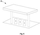
- Fig. 5
- presents schematically a charging station according to the invention in a perspective view.
- A charging
arrangement 1 for supplying electrical energy to an electrical vehicle comprises a chargingarm 2 and a chargingcable 3. A first end of the chargingarm 2 is connected to a first end of the chargingcable 3 and a second end of the chargingcable 3 is equipped with a chargingplug 4. The connection of the first end of the chargingarm 2 with the first end of the chargingcable 3 is watertight and dustproof connection. The watertight and dustproof connection is made with the use of acable gland 10. - The charging
cable 3 and the chargingplug 4 are liquid-cooled with the use ofcooling conduits 9. Thecooling conduits 9 have a form of pipes made of a thermally conductive material and cooling liquid is for example an oil-based liquid. The application of the liquid-cooled chargingcable 3 and the chargingplug 4, in particular with the use ofcooling conduits 9, ensures a reduction of charging times of an electric vehicle. - The charging
arm 2 comprisesbusbars 5 for supplying DC currents to an electrical vehicle and aprotective earth busbar 6 for protecting against electric shocks. Thebusbars 5 for supplying DC currents, for example, can be dimensioned for supplying DC currents of 1500A at a DC voltage of 1500V. In such case, the cross-section of saidbusbars 5 is 1000 mm2 (100 x 10 mm). Further, the chargingarrangement 1 comprises communication andsignal wires 8 that run through the chargingarm 2 and the chargingcable 3 and are connected to the chargingplug 4. The application of the communication andsignal wires 8 that run through the chargingarm 2 and the chargingcable 3 and are connected to the chargingplug 4 ensures automatic start of a charging process of an electrical vehicle, its control and termination. Thebusbars busbars busbars 5 for supplying DC currents to an electrical vehicle are isolated from each other. Further, saidbusbars 5 are isolated from theprotective earth busbar 6 as well as the communication andsignal wires 8. - The charging
arm 2 extends in a horizontal direction. The application of the chargingarm 2 that extends in a horizontal direction eliminates the need of a user of the disclosed chargingarrangement 1 to lift the chargingcable 3 from the ground to connect said chargingcable 3 to a charging input of an electrical vehicle. This completely prevents the user from lifting and carrying such cable. Further, the application of the chargingarm 2 that extends in a horizontal direction prevents the chargingplug 4 from hitting the ground and as a result prevents from mechanical damage to the chargingplug 4. Thus the chargingarrangement 1 according to the invention is more reliable compared to the solutions known from the prior art. - The charging
arrangement 1 comprises further acharging unit 7 and a second end of the chargingarm 2 is rotatably connected to thecharging unit 7 thereby allowing a movement of the first end of the chargingarm 2 relative to a vertical rotation axis (x). - The application of the charging
unit 7 and the rotatory connection of the second end of the chargingarm 2 and thecharging unit 7 allowing a movement of the first end of the chargingarm 2 relative to a vertical rotation axis (x) provides possibility of use of cooling devices of smaller powers, efficiency and sizes that are quieter than commonly used cooling devices. It also leads to reduction in the amount of liquid used for such cooling. Consequently, it leads to increase of the comfort of use of such charging arrangements. This is due to the fact that said application of the chargingunit 7 and the rotatory connection of the second end of the chargingarm 2 and thecharging unit 7 in the chargingarrangement 1 ensures shortening of the chargingcable 3 and reduction of power losses over a path of an electric current transmission compared to the solution known from the state of the art. That, a as a consequence, leads to reduction in heating of the chargingcable 3. - The range of the movement of the first end of the charging
arm 2 relative to the vertical rotation axis (x) is up to 300°, in particular 270°. The application of the range of the movement of the first end of the chargingarm 2 relative to the vertical rotation axis (x) of up to 300°, in particular of 270°, ensures easy movement of the chargingcable 3 to a charging position of an electrical vehicle as the chargingcable 3, together with the chargingarm 2, moves relative to thecharging unit 7. This ensures the capability to support several charging positions, in particular, from 2 to 4 charging positions. - The charging
unit 7 is configured for connecting to an AC grid. The chargingunit 5 can be connected via a transformer and a converter to an AC grid. In the other embodiments, the chargingunit 7 can be configured for connecting to a DC grid. In yet another embodiments the chargingunit 7 can be configured for connecting to a DC power supply. - Furthermore, the charging
arm 2 and thecharging unit 7 are connected by a rotary joint 10. The rotary joint 10 is fixed to the top of the chargingunit 7. The application of the rotary joint 10 to connect the chargingarm 2 and thecharging unit 7 provides a simple and safe connection of the aforementioned elements. - A charging
station 12 comprisingcharging arrangements 1 as above-disclosed. -
- 1 -
- charging arrangement
- 2 -
- charging arm
- 3 -
- charging cable
- 4 -
- charging plug
- 5 -
- busbars for supplying DC currents to an electrical vehicle
- 6-
- protective earth busbar for protecting against electric shocks
- 7 -
- charging unit
- 8 -
- communication and signal wires
- 9 -
- cooling conduits
- 10 -
- rotary joint
- 11 -
- cable gland
- 12 -
- charging station
Claims (15)
- A charging arrangement (1) for supplying electrical energy to an electrical vehicle comprising:- a charging arm (2), and- a charging cable (3),wherein a first end of the charging arm (2) is connected to a first end of the charging cable (3) and a second end of the charging cable (3) is equipped with a charging plug (4),wherein the charging cable (3) and/or the charging plug (4) is liquid-cooled, andwherein the charging arm (2) comprises at least two busbars (5) for supplying DC currents to an electrical vehicle and a protective earth busbar (6) for protecting against electric shocks,characterized in that- the charging arrangement (1) comprises further a charging unit (7), and- a second end of the charging arm (2) is rotatably connected to the charging unit (7) thereby allowing a movement of the first end of the charging arm (2) relative to a vertical rotation axis (x).
- The charging arrangement according to claim 1, wherein the charging arrangement (1) comprises communication and signal wires (8) that run through the charging arm (2) and the charging cable (3) and are connected to the charging plug (4).
- The charging arrangement according to claim 1 or 2, wherein the charging cable (3) and/or the charging plug (4) is liquid-cooled with the use of cooling conduits (9).
- The charging arrangement according to any of the preceding claims, wherein the busbars (5, 6) are made of copper or aluminum.
- The charging arrangement according to any of the preceding claims, wherein the busbars (5, 6) of the charging arm (2) are isolated.
- The charging arrangement according to of the preceding claims, wherein the busbars (5) for supplying DC currents are dimensioned for supplying DC currents up to 3000 A at a DC voltage of 1500 V.
- The charging arrangement according to any of the preceding claims, wherein the charging arm (2) extends in a horizontal direction.
- The charging arrangement according to any of the preceding claims, wherein the range of the movement of the first end of the charging arm (2) relative to the vertical rotation axis (x) is up to 300°.
- The charging arrangement according to claim 8, wherein the range of the movement of the first end of the charging arm (2) relative to the vertical rotation axis (x) is 270°.
- The charging arrangement according to any of the preceding claims, wherein the charging arm (2) and the charging unit (7) are connected by a rotary joint (10).
- The charging arrangement according to claim 10, wherein the rotary joint (10) is fixed to the top of the charging unit (7).
- The charging arrangement according to any of the preceding claims, wherein the connection of the first end of the charging arm (2) with the fist end of the charging cable (3) is watertight and dustproof connection.
- The charging arrangement according to claim 12, the watertight and dustproof connection is made with the use of a cable gland (11).
- The charging arrangement according to any of the preceding claims, wherein the charging unit (7) is configured for connecting to an AC grid, a DC grid or a DC power supply.
- A charging station (12) comprising at least one charging arrangement according to any of the claims from 1 to 14.
Priority Applications (1)
| Application Number | Priority Date | Filing Date | Title |
|---|---|---|---|
| EP23184562.9A EP4491440A1 (en) | 2023-07-10 | 2023-07-10 | A charging arrangement for supplying electrical energy to an electrical vehicle |
Applications Claiming Priority (1)
| Application Number | Priority Date | Filing Date | Title |
|---|---|---|---|
| EP23184562.9A EP4491440A1 (en) | 2023-07-10 | 2023-07-10 | A charging arrangement for supplying electrical energy to an electrical vehicle |
Publications (1)
| Publication Number | Publication Date |
|---|---|
| EP4491440A1 true EP4491440A1 (en) | 2025-01-15 |
Family
ID=87245334
Family Applications (1)
| Application Number | Title | Priority Date | Filing Date |
|---|---|---|---|
| EP23184562.9A Withdrawn EP4491440A1 (en) | 2023-07-10 | 2023-07-10 | A charging arrangement for supplying electrical energy to an electrical vehicle |
Country Status (1)
| Country | Link |
|---|---|
| EP (1) | EP4491440A1 (en) |
Citations (6)
| Publication number | Priority date | Publication date | Assignee | Title |
|---|---|---|---|---|
| JP2011163045A (en) | 2010-02-12 | 2011-08-25 | Honda Motor Co Ltd | Garage |
| US20130076902A1 (en) | 2011-09-26 | 2013-03-28 | Universite Laval | Robotically operated vehicle charging station |
| US20170338006A1 (en) * | 2016-05-20 | 2017-11-23 | Southwire Company, Llc | Liquid Cooled Charging Cable System |
| EP3708412A1 (en) | 2019-03-12 | 2020-09-16 | ABB Schweiz AG | Charging arrangement for supplying electrical energy to an electrical vehicle |
| WO2021170370A1 (en) | 2020-02-27 | 2021-09-02 | Siemens Aktiengesellschaft | Charging system and method for charging an electric vehicle |
| WO2021224708A1 (en) | 2020-05-08 | 2021-11-11 | Abb Schweiz Ag | Automatic electric vehicle charging device |
-
2023
- 2023-07-10 EP EP23184562.9A patent/EP4491440A1/en not_active Withdrawn
Patent Citations (6)
| Publication number | Priority date | Publication date | Assignee | Title |
|---|---|---|---|---|
| JP2011163045A (en) | 2010-02-12 | 2011-08-25 | Honda Motor Co Ltd | Garage |
| US20130076902A1 (en) | 2011-09-26 | 2013-03-28 | Universite Laval | Robotically operated vehicle charging station |
| US20170338006A1 (en) * | 2016-05-20 | 2017-11-23 | Southwire Company, Llc | Liquid Cooled Charging Cable System |
| EP3708412A1 (en) | 2019-03-12 | 2020-09-16 | ABB Schweiz AG | Charging arrangement for supplying electrical energy to an electrical vehicle |
| WO2021170370A1 (en) | 2020-02-27 | 2021-09-02 | Siemens Aktiengesellschaft | Charging system and method for charging an electric vehicle |
| WO2021224708A1 (en) | 2020-05-08 | 2021-11-11 | Abb Schweiz Ag | Automatic electric vehicle charging device |
Similar Documents
| Publication | Publication Date | Title |
|---|---|---|
| RU2558501C2 (en) | Layout structure of charge/discharge wire harness in electric vehicle | |
| CN102714381B (en) | Conduction path connection structure | |
| ES2749898T3 (en) | Vehicle Charging Connectors | |
| CN111845383B (en) | Battery device for vehicle | |
| CN110869237A (en) | Charging arrangement for an electric vehicle and method for operating the charging arrangement | |
| JP5935988B2 (en) | Vehicle power supply system | |
| US12528373B2 (en) | Force assisted charging arrangement for supplying electrical energy to an electrical vehicle | |
| US11095066B2 (en) | Electrical apparatus | |
| JP3638612B2 (en) | Electric drive vehicle | |
| US20040141347A1 (en) | Inverter module for train traction systems | |
| CN108092172B (en) | Compact draw-out type high tension switchgear | |
| JP2025532461A (en) | Current line layout structure and motor vehicle | |
| CN208359942U (en) | A kind of charging unit and the electric vehicle using the charging unit | |
| CN207638472U (en) | A low-voltage high-power motor junction box | |
| US20260014882A1 (en) | Power Line Assembly and Motor Vehicle | |
| CN221041946U (en) | Small ring main unit vehicle with reel | |
| CN220964211U (en) | Cable line installation equipment for power engineering design | |
| CN110497804B (en) | Charging device and electric vehicle using the same | |
| CN223727918U (en) | A snap-on current transformer current ratio testing device | |
| CN223007295U (en) | Bus duct for power transmission and distribution | |
| CN213702146U (en) | Automatic bridge crane welding system | |
| CN212849599U (en) | Armored central metal-enclosed high-voltage switch cabinet | |
| US20250074234A1 (en) | Charging device for charging an electric vehicle | |
| CN220884279U (en) | Integrated high-voltage PDU power distribution system for pure electric sanitation vehicle | |
| CN217362499U (en) | Expansion joint of intensive bus duct |
Legal Events
| Date | Code | Title | Description |
|---|---|---|---|
| PUAI | Public reference made under article 153(3) epc to a published international application that has entered the european phase |
Free format text: ORIGINAL CODE: 0009012 |
|
| STAA | Information on the status of an ep patent application or granted ep patent |
Free format text: STATUS: THE APPLICATION HAS BEEN PUBLISHED |
|
| AK | Designated contracting states |
Kind code of ref document: A1 Designated state(s): AL AT BE BG CH CY CZ DE DK EE ES FI FR GB GR HR HU IE IS IT LI LT LU LV MC ME MK MT NL NO PL PT RO RS SE SI SK SM TR |
|
| STAA | Information on the status of an ep patent application or granted ep patent |
Free format text: STATUS: THE APPLICATION IS DEEMED TO BE WITHDRAWN |
|
| 18D | Application deemed to be withdrawn |
Effective date: 20250716 |