EP3708412A1 - Charging arrangement for supplying electrical energy to an electrical vehicle - Google Patents
Charging arrangement for supplying electrical energy to an electrical vehicle Download PDFInfo
- Publication number
- EP3708412A1 EP3708412A1 EP19162307.3A EP19162307A EP3708412A1 EP 3708412 A1 EP3708412 A1 EP 3708412A1 EP 19162307 A EP19162307 A EP 19162307A EP 3708412 A1 EP3708412 A1 EP 3708412A1
- Authority
- EP
- European Patent Office
- Prior art keywords
- charging
- bus bars
- previous
- arrangement according
- force assisted
- Prior art date
- Legal status (The legal status is an assumption and is not a legal conclusion. Google has not performed a legal analysis and makes no representation as to the accuracy of the status listed.)
- Granted
Links
Images


Classifications
-
- B—PERFORMING OPERATIONS; TRANSPORTING
- B60—VEHICLES IN GENERAL
- B60L—PROPULSION OF ELECTRICALLY-PROPELLED VEHICLES; SUPPLYING ELECTRIC POWER FOR AUXILIARY EQUIPMENT OF ELECTRICALLY-PROPELLED VEHICLES; ELECTRODYNAMIC BRAKE SYSTEMS FOR VEHICLES IN GENERAL; MAGNETIC SUSPENSION OR LEVITATION FOR VEHICLES; MONITORING OPERATING VARIABLES OF ELECTRICALLY-PROPELLED VEHICLES; ELECTRIC SAFETY DEVICES FOR ELECTRICALLY-PROPELLED VEHICLES
- B60L53/00—Methods of charging batteries, specially adapted for electric vehicles; Charging stations or on-board charging equipment therefor; Exchange of energy storage elements in electric vehicles
- B60L53/30—Constructional details of charging stations
- B60L53/35—Means for automatic or assisted adjustment of the relative position of charging devices and vehicles
-
- B—PERFORMING OPERATIONS; TRANSPORTING
- B60—VEHICLES IN GENERAL
- B60L—PROPULSION OF ELECTRICALLY-PROPELLED VEHICLES; SUPPLYING ELECTRIC POWER FOR AUXILIARY EQUIPMENT OF ELECTRICALLY-PROPELLED VEHICLES; ELECTRODYNAMIC BRAKE SYSTEMS FOR VEHICLES IN GENERAL; MAGNETIC SUSPENSION OR LEVITATION FOR VEHICLES; MONITORING OPERATING VARIABLES OF ELECTRICALLY-PROPELLED VEHICLES; ELECTRIC SAFETY DEVICES FOR ELECTRICALLY-PROPELLED VEHICLES
- B60L53/00—Methods of charging batteries, specially adapted for electric vehicles; Charging stations or on-board charging equipment therefor; Exchange of energy storage elements in electric vehicles
- B60L53/10—Methods of charging batteries, specially adapted for electric vehicles; Charging stations or on-board charging equipment therefor; Exchange of energy storage elements in electric vehicles characterised by the energy transfer between the charging station and the vehicle
- B60L53/14—Conductive energy transfer
- B60L53/16—Connectors, e.g. plugs or sockets, specially adapted for charging electric vehicles
-
- B—PERFORMING OPERATIONS; TRANSPORTING
- B60—VEHICLES IN GENERAL
- B60L—PROPULSION OF ELECTRICALLY-PROPELLED VEHICLES; SUPPLYING ELECTRIC POWER FOR AUXILIARY EQUIPMENT OF ELECTRICALLY-PROPELLED VEHICLES; ELECTRODYNAMIC BRAKE SYSTEMS FOR VEHICLES IN GENERAL; MAGNETIC SUSPENSION OR LEVITATION FOR VEHICLES; MONITORING OPERATING VARIABLES OF ELECTRICALLY-PROPELLED VEHICLES; ELECTRIC SAFETY DEVICES FOR ELECTRICALLY-PROPELLED VEHICLES
- B60L53/00—Methods of charging batteries, specially adapted for electric vehicles; Charging stations or on-board charging equipment therefor; Exchange of energy storage elements in electric vehicles
- B60L53/10—Methods of charging batteries, specially adapted for electric vehicles; Charging stations or on-board charging equipment therefor; Exchange of energy storage elements in electric vehicles characterised by the energy transfer between the charging station and the vehicle
- B60L53/14—Conductive energy transfer
- B60L53/18—Cables specially adapted for charging electric vehicles
-
- B—PERFORMING OPERATIONS; TRANSPORTING
- B60—VEHICLES IN GENERAL
- B60L—PROPULSION OF ELECTRICALLY-PROPELLED VEHICLES; SUPPLYING ELECTRIC POWER FOR AUXILIARY EQUIPMENT OF ELECTRICALLY-PROPELLED VEHICLES; ELECTRODYNAMIC BRAKE SYSTEMS FOR VEHICLES IN GENERAL; MAGNETIC SUSPENSION OR LEVITATION FOR VEHICLES; MONITORING OPERATING VARIABLES OF ELECTRICALLY-PROPELLED VEHICLES; ELECTRIC SAFETY DEVICES FOR ELECTRICALLY-PROPELLED VEHICLES
- B60L53/00—Methods of charging batteries, specially adapted for electric vehicles; Charging stations or on-board charging equipment therefor; Exchange of energy storage elements in electric vehicles
- B60L53/30—Constructional details of charging stations
- B60L53/302—Cooling of charging equipment
-
- B—PERFORMING OPERATIONS; TRANSPORTING
- B60—VEHICLES IN GENERAL
- B60L—PROPULSION OF ELECTRICALLY-PROPELLED VEHICLES; SUPPLYING ELECTRIC POWER FOR AUXILIARY EQUIPMENT OF ELECTRICALLY-PROPELLED VEHICLES; ELECTRODYNAMIC BRAKE SYSTEMS FOR VEHICLES IN GENERAL; MAGNETIC SUSPENSION OR LEVITATION FOR VEHICLES; MONITORING OPERATING VARIABLES OF ELECTRICALLY-PROPELLED VEHICLES; ELECTRIC SAFETY DEVICES FOR ELECTRICALLY-PROPELLED VEHICLES
- B60L53/00—Methods of charging batteries, specially adapted for electric vehicles; Charging stations or on-board charging equipment therefor; Exchange of energy storage elements in electric vehicles
- B60L53/30—Constructional details of charging stations
- B60L53/305—Communication interfaces
-
- B—PERFORMING OPERATIONS; TRANSPORTING
- B60—VEHICLES IN GENERAL
- B60L—PROPULSION OF ELECTRICALLY-PROPELLED VEHICLES; SUPPLYING ELECTRIC POWER FOR AUXILIARY EQUIPMENT OF ELECTRICALLY-PROPELLED VEHICLES; ELECTRODYNAMIC BRAKE SYSTEMS FOR VEHICLES IN GENERAL; MAGNETIC SUSPENSION OR LEVITATION FOR VEHICLES; MONITORING OPERATING VARIABLES OF ELECTRICALLY-PROPELLED VEHICLES; ELECTRIC SAFETY DEVICES FOR ELECTRICALLY-PROPELLED VEHICLES
- B60L53/00—Methods of charging batteries, specially adapted for electric vehicles; Charging stations or on-board charging equipment therefor; Exchange of energy storage elements in electric vehicles
- B60L53/30—Constructional details of charging stations
- B60L53/31—Charging columns specially adapted for electric vehicles
-
- H—ELECTRICITY
- H02—GENERATION; CONVERSION OR DISTRIBUTION OF ELECTRIC POWER
- H02G—INSTALLATION OF ELECTRIC CABLES OR LINES, OR OF COMBINED OPTICAL AND ELECTRIC CABLES OR LINES
- H02G11/00—Arrangements of electric cables or lines between relatively-movable parts
-
- H—ELECTRICITY
- H02—GENERATION; CONVERSION OR DISTRIBUTION OF ELECTRIC POWER
- H02J—ELECTRIC POWER NETWORKS; CIRCUIT ARRANGEMENTS OR SYSTEMS FOR SUPPLYING OR DISTRIBUTING ELECTRIC POWER; SYSTEMS FOR STORING ELECTRIC ENERGY
- H02J7/00—Circuit arrangements for charging or discharging batteries or for supplying loads from batteries
- H02J7/02—Circuit arrangements for charging or discharging batteries or for supplying loads from batteries for charging batteries from AC mains by converters
-
- H—ELECTRICITY
- H02—GENERATION; CONVERSION OR DISTRIBUTION OF ELECTRIC POWER
- H02J—ELECTRIC POWER NETWORKS; CIRCUIT ARRANGEMENTS OR SYSTEMS FOR SUPPLYING OR DISTRIBUTING ELECTRIC POWER; SYSTEMS FOR STORING ELECTRIC ENERGY
- H02J7/00—Circuit arrangements for charging or discharging batteries or for supplying loads from batteries
- H02J7/70—Circuit arrangements for charging or discharging batteries or for supplying loads from batteries characterised by the mechanical construction
- H02J7/751—Circuit arrangements for charging or discharging batteries or for supplying loads from batteries characterised by the mechanical construction concerning the insertion or the connection of the batteries
-
- Y—GENERAL TAGGING OF NEW TECHNOLOGICAL DEVELOPMENTS; GENERAL TAGGING OF CROSS-SECTIONAL TECHNOLOGIES SPANNING OVER SEVERAL SECTIONS OF THE IPC; TECHNICAL SUBJECTS COVERED BY FORMER USPC CROSS-REFERENCE ART COLLECTIONS [XRACs] AND DIGESTS
- Y02—TECHNOLOGIES OR APPLICATIONS FOR MITIGATION OR ADAPTATION AGAINST CLIMATE CHANGE
- Y02T—CLIMATE CHANGE MITIGATION TECHNOLOGIES RELATED TO TRANSPORTATION
- Y02T10/00—Road transport of goods or passengers
- Y02T10/60—Other road transportation technologies with climate change mitigation effect
- Y02T10/70—Energy storage systems for electromobility, e.g. batteries
-
- Y—GENERAL TAGGING OF NEW TECHNOLOGICAL DEVELOPMENTS; GENERAL TAGGING OF CROSS-SECTIONAL TECHNOLOGIES SPANNING OVER SEVERAL SECTIONS OF THE IPC; TECHNICAL SUBJECTS COVERED BY FORMER USPC CROSS-REFERENCE ART COLLECTIONS [XRACs] AND DIGESTS
- Y02—TECHNOLOGIES OR APPLICATIONS FOR MITIGATION OR ADAPTATION AGAINST CLIMATE CHANGE
- Y02T—CLIMATE CHANGE MITIGATION TECHNOLOGIES RELATED TO TRANSPORTATION
- Y02T10/00—Road transport of goods or passengers
- Y02T10/60—Other road transportation technologies with climate change mitigation effect
- Y02T10/7072—Electromobility specific charging systems or methods for batteries, ultracapacitors, supercapacitors or double-layer capacitors
-
- Y—GENERAL TAGGING OF NEW TECHNOLOGICAL DEVELOPMENTS; GENERAL TAGGING OF CROSS-SECTIONAL TECHNOLOGIES SPANNING OVER SEVERAL SECTIONS OF THE IPC; TECHNICAL SUBJECTS COVERED BY FORMER USPC CROSS-REFERENCE ART COLLECTIONS [XRACs] AND DIGESTS
- Y02—TECHNOLOGIES OR APPLICATIONS FOR MITIGATION OR ADAPTATION AGAINST CLIMATE CHANGE
- Y02T—CLIMATE CHANGE MITIGATION TECHNOLOGIES RELATED TO TRANSPORTATION
- Y02T90/00—Enabling technologies or technologies with a potential or indirect contribution to GHG emissions mitigation
- Y02T90/10—Technologies relating to charging of electric vehicles
- Y02T90/12—Electric charging stations
-
- Y—GENERAL TAGGING OF NEW TECHNOLOGICAL DEVELOPMENTS; GENERAL TAGGING OF CROSS-SECTIONAL TECHNOLOGIES SPANNING OVER SEVERAL SECTIONS OF THE IPC; TECHNICAL SUBJECTS COVERED BY FORMER USPC CROSS-REFERENCE ART COLLECTIONS [XRACs] AND DIGESTS
- Y02—TECHNOLOGIES OR APPLICATIONS FOR MITIGATION OR ADAPTATION AGAINST CLIMATE CHANGE
- Y02T—CLIMATE CHANGE MITIGATION TECHNOLOGIES RELATED TO TRANSPORTATION
- Y02T90/00—Enabling technologies or technologies with a potential or indirect contribution to GHG emissions mitigation
- Y02T90/10—Technologies relating to charging of electric vehicles
- Y02T90/14—Plug-in electric vehicles
-
- Y—GENERAL TAGGING OF NEW TECHNOLOGICAL DEVELOPMENTS; GENERAL TAGGING OF CROSS-SECTIONAL TECHNOLOGIES SPANNING OVER SEVERAL SECTIONS OF THE IPC; TECHNICAL SUBJECTS COVERED BY FORMER USPC CROSS-REFERENCE ART COLLECTIONS [XRACs] AND DIGESTS
- Y02—TECHNOLOGIES OR APPLICATIONS FOR MITIGATION OR ADAPTATION AGAINST CLIMATE CHANGE
- Y02T—CLIMATE CHANGE MITIGATION TECHNOLOGIES RELATED TO TRANSPORTATION
- Y02T90/00—Enabling technologies or technologies with a potential or indirect contribution to GHG emissions mitigation
- Y02T90/10—Technologies relating to charging of electric vehicles
- Y02T90/16—Information or communication technologies improving the operation of electric vehicles
-
- Y—GENERAL TAGGING OF NEW TECHNOLOGICAL DEVELOPMENTS; GENERAL TAGGING OF CROSS-SECTIONAL TECHNOLOGIES SPANNING OVER SEVERAL SECTIONS OF THE IPC; TECHNICAL SUBJECTS COVERED BY FORMER USPC CROSS-REFERENCE ART COLLECTIONS [XRACs] AND DIGESTS
- Y02—TECHNOLOGIES OR APPLICATIONS FOR MITIGATION OR ADAPTATION AGAINST CLIMATE CHANGE
- Y02T—CLIMATE CHANGE MITIGATION TECHNOLOGIES RELATED TO TRANSPORTATION
- Y02T90/00—Enabling technologies or technologies with a potential or indirect contribution to GHG emissions mitigation
- Y02T90/10—Technologies relating to charging of electric vehicles
- Y02T90/16—Information or communication technologies improving the operation of electric vehicles
- Y02T90/167—Systems integrating technologies related to power network operation and communication or information technologies for supporting the interoperability of electric or hybrid vehicles, i.e. smartgrids as interface for battery charging of electric vehicles [EV] or hybrid vehicles [HEV]
-
- Y—GENERAL TAGGING OF NEW TECHNOLOGICAL DEVELOPMENTS; GENERAL TAGGING OF CROSS-SECTIONAL TECHNOLOGIES SPANNING OVER SEVERAL SECTIONS OF THE IPC; TECHNICAL SUBJECTS COVERED BY FORMER USPC CROSS-REFERENCE ART COLLECTIONS [XRACs] AND DIGESTS
- Y04—INFORMATION OR COMMUNICATION TECHNOLOGIES HAVING AN IMPACT ON OTHER TECHNOLOGY AREAS
- Y04S—SYSTEMS INTEGRATING TECHNOLOGIES RELATED TO POWER NETWORK OPERATION, COMMUNICATION OR INFORMATION TECHNOLOGIES FOR IMPROVING THE ELECTRICAL POWER GENERATION, TRANSMISSION, DISTRIBUTION, MANAGEMENT OR USAGE, i.e. SMART GRIDS
- Y04S30/00—Systems supporting specific end-user applications in the sector of transportation
- Y04S30/10—Systems supporting the interoperability of electric or hybrid vehicles
- Y04S30/12—Remote or cooperative charging
Definitions
- the invention relates to a charging arrangement for supplying electrical energy to an electrical vehicle, comprising a charging cable having a first charging cable end and a charging cable second end and a charging connector connected to the first charging cable end.
- the invention further relates to an electric vehicle charge equipment, EVSE, comprising the force assisted charging arrangement and configured for connecting to an AC grid.
- EVSE electric vehicle charge equipment
- Electric vehicle, EV, direct current, DC, fast charging systems and methods often use a so-called Combined Charging System, CCS, protocol according to IEC 61851-23 and SAE J1772 standard for charging electrical vehicles both in the US and in the European Union, EU.
- CCS Combined Charging System
- High power charging requires charging cables which can carry 500A current at a voltage of 1000V.
- the liquid cooling allows conductors within the charging cable to become thinner, and thereby easier to use, because excessive heat due to high charge currents and charging cable internal resistances is taken care of.
- a drawback of liquid cooled charging cables is that the charging cable becomes very stiff and heavy.
- weight of such high-power liquid cooled charging cables is increasing and is becoming too much for an ordinary person to handle.
- charging connectors are vulnerable components that are easily damaged if dropped or handled incorrectly and cooled charging cables only offer limited extensions to those power levels. Therefore, robotic systems have been developed for overcoming these disadvantages. However, such robotic systems are expensive and potentially dangerous for humans being too close to such robotic arms.
- a force assisted charging arrangement for supplying electrical energy to an electrical vehicle via a first set of bus bars and a second set of bus bars, comprising
- a human connecting the charging cable via the charging connector to the electrical vehicle does not need to lift the cable from ground for connecting the cable to the electrical vehicle. Such way lifting a heavy and stiffy charging cable can be completely avoided.
- the length of the charging cable is preferably dimensioned such that the first charging cable end respectively the charging connector is arranged adjacent to a socket of the electrical vehicle, into which the charging connector can be plugged for charging the electrical vehicle with electrical energy. Due to gravity the charging cable will hang down from the second set of bus bars and thus extend in vertical direction.
- the charging cable is dimensioned such that neither the charging cable nor the charging connector hanging down from the second set of bus bars touches ground.
- the charging cable is provided length-adjustable. Such way charging sockets having different heights in respect to ground can be connected without lifting the charging connector.
- the charging connector can be easily rotated from one side to another side in respect to the electrical vehicle.
- charging sockets provided on an arbitrary side of an electrical vehicle can be connected by the charging connector without having the need to lift the charging connector or to move the charging cable over ground from one side to another side of the electrical vehicle.
- the charging cable can be preferably freely rotated in respect to the first set of bus bars, even liquid cooled charging cables that are very stiff and heavy can be easily handled by any human with the proposed force assisted charging arrangement.
- the bus bars and/or the charging cable preferably comprise DC conductors having a diameter of ⁇ 25 mm 2 , 50 mm 2 or 70 mm 2 and/or a length of ⁇ 4 m, 5 m or 7,5m and ⁇ 5 m, 7,5 m or 10 m and/or are dimensioned for supplying in particular DC currents up to 500A or more at a DC voltage of 1000V or more.
- the electrical vehicle can be provided as an electrical car, an ebus, a truck or any other electrical vehicle means.
- the second end is rotatable around 360° around the first end.
- the charging socket is provided as the charging cable and the charging connector can be easily rotated towards a suitable position in regard the electrical vehicle.
- the second set of bus bars can be rotated in a plane parallel to ground and/or in horizontal direction.
- first set of bus bars and/or the second set of bus bars are provided as linear arms and/or extend in horizontal direction.
- the bus bars preferably comprise a linear extension of 2, 3, 4 or 5 meters and/or extend parallel to each other.
- first end is connected rotatable to the first set of bus bars via a joint.
- the joint preferably comprises conductors for connecting the respective bus bars of the first set of bus bars and the second set of bus bars.
- the force assisted charging arrangement comprises a communication cable, which runs parallel to the first and a second set of bus bars and is connected to the charging connector.
- the communication cable may comprise further conductors, such as, for example, a Proximity Pilot, PP, line for a PP signal, a Control Pilot, CP, line for a CP signal line and/or a PE line for a PE signal.
- PP line, CP line and/or PE line and respectively signalling are preferably implemented according to the so-called Combined Charging System, CCS, protocol, in particular according to IEC 61851 or IEC 61851-23 standard.
- the communication cable is integrated within the charging cable.
- the charging cable and/or the charging connector is liquid cooled.
- a cooling device can be provided, which is preferably arranged at an EVSE as described below and/or which is configured that the cooling liquid is conveyed from a first end to a second, opposite end of the charging cable towards the charging connector, and thereafter from the second end to the first end.
- the cooling liquid is preferably provided as an oil-based coolant thereby allowing that the cooling liquid comes into contact with unshielded copper conductors of the charging cable.
- the charging connector is provided as reverse plug.
- a reverse plug means preferably that the charging connector comprises, when plugged into the electrical vehicle, a bending upward so that the charging cable is inserted in vertical manner from above into the charging connector. Providing the charging connector as reverse plug simplifies handling when plugging the charging connector into the charging socket.
- first set of bus bars and the second set of bus bars each comprise two or at least two bus bars and/or whereby the bus bars are isolated.
- the joint comprises a respective number of conductors for connecting the respective bus bars of the first set of bus bars and the second set of bus bars. Further preferably, the bus bars isolated from each other.
- the force assisted charging arrangement comprises a support frame arranged on ground, which holds the first set of bus bars arranged distant and fixed in respect to ground.
- the support frame preferably comprises a hollow frame.
- the support frame comprises two triangles, which are arranged parallel and distant to each other with each one side attached to ground.
- the first set of two bus bars is preferably attached with one end to corners of the triangles opposite to ground thereby extending in linear direction.
- the support frame is dimensioned such that the electrical vehicle can be parked at least partly underneath the bus bars.
- the support frame and/or the first set of bus bars can be attached to or underneath a roof or any other overhang.
- the force assisted charging arrangement comprises the electrical vehicle, whereby the first set of bus bars and the second set of bus bars are arranged above the electrical vehicle such that the electrical vehicle can drive underneath the first set of bus bars and the second set of bus bars.
- the electrical vehicle simply needs to be parked underneath the first set of bus bars.
- the second set of bus bars is rotated until the charging cable and the charging connector rest close to charging socket of the electrical vehicle. Finally, the charging connector is plugged into the charging socket such that charging can start.
- the object is further solved by an electric vehicle charge equipment, EVSE, comprising the force assisted charging arrangement as described before and configured for connecting to an AC grid.
- the EVSE may comprise a transformer and/or a converter for connecting to respectively receiving electrical energy from the AC grid, which is transformed and/or converted to DC for being supplied to the first set of bus bars.
- the EVSE is configured for charging the electrical vehicle by using a Combined Charge System, CCS, protocol according to IEC 61851-23 and/or SAE J1772 standard and/or whereby the charging connector and/or the charging cable are provided according to IEC 62196 standard.
- the Combined Charging System, CCS, protocol is a fast charging method for charging electric vehicles delivering high-voltage direct current via a charging connector derived from SAE J1772 standard (IEC Type 1) or IEC Type 2 connector.
- Automobile manufactures that support CCS include Jaguar, Volkswagen, General Motors, BMW, Daimler, Ford, FCA, Tesla and Hyundai.
- the CSS standard is controlled by the so called CharIN consortium.
- the EVSE and the charging arrangement are applicable to different type of electrical vehicles, including for examples electrical busses.
- the EVSE and/or the charging arrangement is configured for charging the electrical vehicles with a DC input voltage up to 1500 V DC.
- Figs. 1 to 3 show a force assisted charging arrangement for supplying electrical energy to an electrical vehicle 1 according to a preferred embodiment in different perspective schematic views.
- the charging arrangement comprises a first set of two linear bus bars 2, which are arranged distant and fixed in respect to ground 3 on a hollow support frame 4.
- the support frame 4 comprise two triangles arranged parallel and distant to each other with each one side on ground 3.
- the first set of two bus bars 2 is attached with one end to corners of the triangles opposite to ground 3 thereby extending in linear direction such that the electrical vehicle 1 can be positioned underneath the other opposite end of the first set of two linear bus bars 2.
- the first set of bus bars 2 comprises a linear extension between the opposite ends of 4 meters.
- a joint 5 is provided for rotatably connecting the first set of bus bars 2 with a second set of two linear bus bars 6, of which a first end is attached to the joint 5.
- the second set of bus bars 6 extend horizontal in respect to ground 3, whereby a second opposite end of the second set of bus bars 6 is rotatable by 360° around a rotation axis extending in vertical direction and defined by the joint 5, as can be seen from Figs. 2 and 3 showing the second opposite end in different positions.
- the second set of bus bars 6 comprises a linear extension between the first and second end of 2 meters and is provided as an arm.
- Both the first set of bus bars 2 and the second set of bus bars 6 comprise two bus bars for supplying DC current to the electrical vehicle 1, whereby the respective bus bars are isolated from each other.
- the charging arrangement further comprises a liquid cooled charging cable 7 having a first charging cable end and a second charging cable end.
- the second charging cable end is connected to the second end of the second set of bus bars 6. Due to gravity and weight of the liquid cooling, the liquid cooled charging cable 7 "hangs" down from the second end of the second set of bus bars 6 in a vertical manner and comprises a length such that a charging connector 8 connected to the first charging cable end can be easily plugged by a human into a respective socket of the electrical vehicle 1 without the need to lift the charging connector 8.
- the charging connector 8 is provided as a reverse plug.
- Provided as a reverse plug means that the charging connector 8 comprises, when plugged into the electrical vehicle 1, a bending upward such that the charging cable 7 is inserted in vertical manner from above into the charging connector 8.
- the first set of bus bars 2, the second set of bus bars 6, the liquid cooled charging cable 7 and liquid cooled charging connector 8 are dimensioned to charge the electrical vehicle with a current of 500A DC at a voltage if 1000V DC.
- a communication cable 9 is provided, which runs parallel to the first and to the second set of bus bars 2, 6 and is connected to the charging connector 8.
- the communication cable 9 is integrated into the charging cable 7 as additional conductors to the conductors carrying the charging currents.
- the charging arrangement For receiving electrical energy to charge the electrical vehicle 1 with a respective DC current, the charging arrangement is connected to an electric vehicle charge equipment, EVSE, 10.
- the EVSE 10 is connected via a transformer and a converter to an AC grid 11.
- the EVSE 10 is configured for charging the electrical vehicle 1 by using a Combined Charge System, CCS, protocol according to IEC 61851-23 and/or SAE J1772 standard, thereby allowing said charging currents of 500A DC or more at 1000V DC or more.
- CCS Combined Charge System
- the charging connector 8 and the charging cable 7 are provided according to IEC 62196 standard.
- the proposed solution provides a force compensating mechanism that provides for an easy and simple possibility for connecting the charging connector 8 to different types of electrical vehicles 1 without having the need of lifting a heavy and stiff charging cable 7.
- the second set of bus bars 6 in form of an arm can freely rotated by 360° in respect to the first set of bus bars 2, it does not matter on which side of the electrical vehicle 1 the charging socket is provided.
- the second set of bus bars 6 is rotated around the electrical vehicle until the charging connector 8 becomes close to the charging socket.
Landscapes
- Engineering & Computer Science (AREA)
- Power Engineering (AREA)
- Transportation (AREA)
- Mechanical Engineering (AREA)
- Charge And Discharge Circuits For Batteries Or The Like (AREA)
- Electric Propulsion And Braking For Vehicles (AREA)
Abstract
Description
- The invention relates to a charging arrangement for supplying electrical energy to an electrical vehicle, comprising a charging cable having a first charging cable end and a charging cable second end and a charging connector connected to the first charging cable end. The invention further relates to an electric vehicle charge equipment, EVSE, comprising the force assisted charging arrangement and configured for connecting to an AC grid.
- Electric vehicle, EV, direct current, DC, fast charging systems and methods often use a so-called Combined Charging System, CCS, protocol according to IEC 61851-23 and SAE J1772 standard for charging electrical vehicles both in the US and in the European Union, EU. As charge currents increase, liquid cooled charging cables for connecting an Electric Vehicle Supply Equipment, EVSE, via a charging connector with the electrical vehicle are becoming more commonly used. High power charging requires charging cables which can carry 500A current at a voltage of 1000V. The liquid cooling allows conductors within the charging cable to become thinner, and thereby easier to use, because excessive heat due to high charge currents and charging cable internal resistances is taken care of.
- A drawback of liquid cooled charging cables is that the charging cable becomes very stiff and heavy. In addition, weight of such high-power liquid cooled charging cables is increasing and is becoming too much for an ordinary person to handle. Besides that, charging connectors are vulnerable components that are easily damaged if dropped or handled incorrectly and cooled charging cables only offer limited extensions to those power levels. Therefore, robotic systems have been developed for overcoming these disadvantages. However, such robotic systems are expensive and potentially dangerous for humans being too close to such robotic arms.
- It is therefore an object of the invention to provide a charging arrangement for connecting a liquid cooled charging cable to an electrical vehicle in a simple, cheap and secure manner independent of the weight and stiffness of the charging cable.
- The object of the invention is solved by the features of the independent claims. Preferred embodiments are detailed in the dependent claims.
- Thus, the object is solved by a force assisted charging arrangement for supplying electrical energy to an electrical vehicle via a first set of bus bars and a second set of bus bars, comprising
- the first set of bus bars arranged distant and fixed in respect to ground,
- the second set of bus bars having a first end and a second end, the first end connected rotatable to the first set of bus bars thereby allowing a rotation of the second end around a vertical rotation axis,
- a charging cable having a first charging cable end and a second charging cable end, the second charging cable end connected to the second end of the second set of bus bars, and
- a charging connector connected to the first charging cable end.
- It is therefore a key point of the invention to provide a force assisted charging arrangement which absorbs weight of the charging cable thereby providing easy handling and connectability to different types of electrical vehicles independent of the weight and stiffness of the charging cable. As the charging cable is attached to the second set of bus bars and thus preferably hold above ground, a human connecting the charging cable via the charging connector to the electrical vehicle does not need to lift the cable from ground for connecting the cable to the electrical vehicle. Such way lifting a heavy and stiffy charging cable can be completely avoided.
- The length of the charging cable is preferably dimensioned such that the first charging cable end respectively the charging connector is arranged adjacent to a socket of the electrical vehicle, into which the charging connector can be plugged for charging the electrical vehicle with electrical energy. Due to gravity the charging cable will hang down from the second set of bus bars and thus extend in vertical direction. Preferably, the charging cable is dimensioned such that neither the charging cable nor the charging connector hanging down from the second set of bus bars touches ground. Preferably, the charging cable is provided length-adjustable. Such way charging sockets having different heights in respect to ground can be connected without lifting the charging connector.
- As the charging cable and the charging connector are rotatable around the vertical rotation axis, the charging connector can be easily rotated from one side to another side in respect to the electrical vehicle. Thus, charging sockets provided on an arbitrary side of an electrical vehicle can be connected by the charging connector without having the need to lift the charging connector or to move the charging cable over ground from one side to another side of the electrical vehicle. As due to the proposed solution weight of the charging cable does not matter anymore, and as the charging cable can be preferably freely rotated in respect to the first set of bus bars, even liquid cooled charging cables that are very stiff and heavy can be easily handled by any human with the proposed force assisted charging arrangement.
- The bus bars and/or the charging cable preferably comprise DC conductors having a diameter of ≥ 25 mm2, 50 mm2 or 70 mm2 and/or a length of ≥ 4 m, 5 m or 7,5m and ≤ 5 m, 7,5 m or 10 m and/or are dimensioned for supplying in particular DC currents up to 500A or more at a DC voltage of 1000V or more. The electrical vehicle can be provided as an electrical car, an ebus, a truck or any other electrical vehicle means.
- In a preferred implementation the second end is rotatable around 360° around the first end. Such way it does not matter on which side of the electrical vehicle the charging socket is provided as the charging cable and the charging connector can be easily rotated towards a suitable position in regard the electrical vehicle. Preferably, the second set of bus bars can be rotated in a plane parallel to ground and/or in horizontal direction.
- In another preferred implementation the first set of bus bars and/or the second set of bus bars are provided as linear arms and/or extend in horizontal direction. The bus bars preferably comprise a linear extension of 2, 3, 4 or 5 meters and/or extend parallel to each other. In a further preferred implementation, the first end is connected rotatable to the first set of bus bars via a joint. The joint preferably comprises conductors for connecting the respective bus bars of the first set of bus bars and the second set of bus bars.
- In another preferred implementation the force assisted charging arrangement comprises a communication cable, which runs parallel to the first and a second set of bus bars and is connected to the charging connector. The communication cable may comprise further conductors, such as, for example, a Proximity Pilot, PP, line for a PP signal, a Control Pilot, CP, line for a CP signal line and/or a PE line for a PE signal. PP line, CP line and/or PE line and respectively signalling are preferably implemented according to the so-called Combined Charging System, CCS, protocol, in particular according to IEC 61851 or IEC 61851-23 standard. In a further preferred implementation, the communication cable is integrated within the charging cable.
- In another preferred implementation, the charging cable and/or the charging connector is liquid cooled. For cooling the charging cable and/or the charging connector, a cooling device can be provided, which is preferably arranged at an EVSE as described below and/or which is configured that the cooling liquid is conveyed from a first end to a second, opposite end of the charging cable towards the charging connector, and thereafter from the second end to the first end. The cooling liquid is preferably provided as an oil-based coolant thereby allowing that the cooling liquid comes into contact with unshielded copper conductors of the charging cable.
- In a further preferred implementation, the charging connector is provided as reverse plug. Provided as a reverse plug means preferably that the charging connector comprises, when plugged into the electrical vehicle, a bending upward so that the charging cable is inserted in vertical manner from above into the charging connector. Providing the charging connector as reverse plug simplifies handling when plugging the charging connector into the charging socket.
- In another preferred implementation the first set of bus bars and the second set of bus bars each comprise two or at least two bus bars and/or whereby the bus bars are isolated. Preferably, the joint comprises a respective number of conductors for connecting the respective bus bars of the first set of bus bars and the second set of bus bars. Further preferably, the bus bars isolated from each other.
- In a further preferred implementation, the force assisted charging arrangement comprises a support frame arranged on ground, which holds the first set of bus bars arranged distant and fixed in respect to ground. The support frame preferably comprises a hollow frame. Further preferably, the support frame comprises two triangles, which are arranged parallel and distant to each other with each one side attached to ground. The first set of two bus bars is preferably attached with one end to corners of the triangles opposite to ground thereby extending in linear direction. Preferably the support frame is dimensioned such that the electrical vehicle can be parked at least partly underneath the bus bars. Alternatively, the support frame and/or the first set of bus bars can be attached to or underneath a roof or any other overhang.
- In another preferred implementation the force assisted charging arrangement comprises the electrical vehicle, whereby the first set of bus bars and the second set of bus bars are arranged above the electrical vehicle such that the electrical vehicle can drive underneath the first set of bus bars and the second set of bus bars. Such way charging of the electrical vehicle becomes very easy as the electrical vehicle simply needs to be parked underneath the first set of bus bars. Once parked, the second set of bus bars is rotated until the charging cable and the charging connector rest close to charging socket of the electrical vehicle. Finally, the charging connector is plugged into the charging socket such that charging can start.
- The object is further solved by an electric vehicle charge equipment, EVSE, comprising the force assisted charging arrangement as described before and configured for connecting to an AC grid. The EVSE may comprise a transformer and/or a converter for connecting to respectively receiving electrical energy from the AC grid, which is transformed and/or converted to DC for being supplied to the first set of bus bars.
- In another preferred implementation the EVSE is configured for charging the electrical vehicle by using a Combined Charge System, CCS, protocol according to IEC 61851-23 and/or SAE J1772 standard and/or whereby the charging connector and/or the charging cable are provided according to IEC 62196 standard. The Combined Charging System, CCS, protocol is a fast charging method for charging electric vehicles delivering high-voltage direct current via a charging connector derived from SAE J1772 standard (IEC Type 1) or IEC Type 2 connector. Automobile manufactures that support CCS include Jaguar, Volkswagen, General Motors, BMW, Daimler, Ford, FCA, Tesla and Hyundai. The CSS standard is controlled by the so called CharIN consortium. Besides other protocols such as, for example, CHAdeMO, as abbreviation of CHArge de Move, or GB/T, in particular according to 20234.3-2011 standard, can also be used with the described EVSE respectively the method. The EVSE and the charging arrangement are applicable to different type of electrical vehicles, including for examples electrical busses. Preferably, the EVSE and/or the charging arrangement is configured for charging the electrical vehicles with a DC input voltage up to 1500 V DC.
- These and other aspects of the invention will be apparent from and elucidated with reference to the embodiments described hereinafter.
- In the drawings:
-
Fig. 1 shows a force assisted charging arrangement for supplying electrical energy to an electrical vehicle according to a preferred embodiment in a perspective schematic view, -
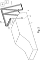
Fig. 2 shows the force assisted charging arrangement according toFig. 1 in another perspective schematic view, and -
Fig. 3 shows the force assisted charging arrangement according toFig. 2 in another perspective schematic view. -
Figs. 1 to 3 show a force assisted charging arrangement for supplying electrical energy to an electrical vehicle 1 according to a preferred embodiment in different perspective schematic views. The charging arrangement comprises a first set of two linear bus bars 2, which are arranged distant and fixed in respect toground 3 on ahollow support frame 4. Thesupport frame 4 comprise two triangles arranged parallel and distant to each other with each one side onground 3. The first set of two bus bars 2 is attached with one end to corners of the triangles opposite toground 3 thereby extending in linear direction such that the electrical vehicle 1 can be positioned underneath the other opposite end of the first set of two linear bus bars 2. The first set of bus bars 2 comprises a linear extension between the opposite ends of 4 meters. - At the other opposite end, a joint 5 is provided for rotatably connecting the first set of bus bars 2 with a second set of two linear bus bars 6, of which a first end is attached to the
joint 5. Such way the second set of bus bars 6 extend horizontal in respect toground 3, whereby a second opposite end of the second set of bus bars 6 is rotatable by 360° around a rotation axis extending in vertical direction and defined by the joint 5, as can be seen fromFigs. 2 and3 showing the second opposite end in different positions. The second set of bus bars 6 comprises a linear extension between the first and second end of 2 meters and is provided as an arm. Both the first set of bus bars 2 and the second set of bus bars 6 comprise two bus bars for supplying DC current to the electrical vehicle 1, whereby the respective bus bars are isolated from each other. - The charging arrangement further comprises a liquid cooled charging cable 7 having a first charging cable end and a second charging cable end. The second charging cable end is connected to the second end of the second set of bus bars 6. Due to gravity and weight of the liquid cooling, the liquid cooled charging cable 7 "hangs" down from the second end of the second set of bus bars 6 in a vertical manner and comprises a length such that a charging
connector 8 connected to the first charging cable end can be easily plugged by a human into a respective socket of the electrical vehicle 1 without the need to lift the chargingconnector 8. For facilitating easy connection, the chargingconnector 8 is provided as a reverse plug. Provided as a reverse plug means that the chargingconnector 8 comprises, when plugged into the electrical vehicle 1, a bending upward such that the charging cable 7 is inserted in vertical manner from above into the chargingconnector 8. - The first set of bus bars 2, the second set of bus bars 6, the liquid cooled charging cable 7 and liquid cooled charging
connector 8 are dimensioned to charge the electrical vehicle with a current of 500A DC at a voltage if 1000V DC. For exchanging charging information between the electrical vehicle 1, a communication cable 9 is provided, which runs parallel to the first and to the second set of bus bars 2, 6 and is connected to the chargingconnector 8. The communication cable 9 is integrated into the charging cable 7 as additional conductors to the conductors carrying the charging currents. - For receiving electrical energy to charge the electrical vehicle 1 with a respective DC current, the charging arrangement is connected to an electric vehicle charge equipment, EVSE, 10. The
EVSE 10 is connected via a transformer and a converter to anAC grid 11. TheEVSE 10 is configured for charging the electrical vehicle 1 by using a Combined Charge System, CCS, protocol according to IEC 61851-23 and/or SAE J1772 standard, thereby allowing said charging currents of 500A DC or more at 1000V DC or more. In an equal manner the chargingconnector 8 and the charging cable 7 are provided according to IEC 62196 standard. - The proposed solution provides a force compensating mechanism that provides for an easy and simple possibility for connecting the charging
connector 8 to different types of electrical vehicles 1 without having the need of lifting a heavy and stiff charging cable 7. As the second set of bus bars 6 in form of an arm can freely rotated by 360° in respect to the first set of bus bars 2, it does not matter on which side of the electrical vehicle 1 the charging socket is provided. For connecting the chargingconnector 8 to the electrical vehicle 1, the second set of bus bars 6 is rotated around the electrical vehicle until the chargingconnector 8 becomes close to the charging socket. - While the invention has been illustrated and described in detail in the drawings and foregoing description, such illustration and description are to be considered illustrative or exemplary and not restrictive; the invention is not limited to the disclosed embodiments. Other variations to be disclosed embodiments can be understood and effected by those skilled in the art in practicing the claimed invention, from a study of the drawings, the disclosure, and the appended claims. In the claims, the word "comprising" does not exclude other elements or steps, and the indefinite article "a" or "an" does not exclude a plurality. The mere fact that certain measures are recited in mutually different dependent claims does not indicate that a combination of these measures cannot be used to advantage. Any reference signs in the claims should not be construed as limiting scope.
-
- 1
- electrical vehicle
- 2
- first set of bus bars
- 3
- ground
- 4
- support frame
- 5
- joint
- 6
- second set of bus bars
- 7
- charging cable
- 8
- charging connector
- 9
- communication cable
- 10
- Electric vehicle charge equipment
- 11
- AC grid
Claims (13)
- Force assisted charging arrangement for supplying electrical energy to an electrical vehicle (1) via a first set of bus bars (2) and a second set of bus bars (6), comprising
the first set of bus bars (2) arranged distant and fixed in respect to ground (3),
the second set of bus bars (6) having a first end and a second end, the first end connected rotatable to the first set of bus bars (2) thereby allowing a rotation of the second end around a vertical rotation axis,
a charging cable (7) having a first charging cable end and a second charging cable end, the second charging cable end connected to the second end of the second set of bus bars (6), and
a charging connector (8) connected to the first charging cable end. - Force assisted charging arrangement according to the previous claim, whereby the second end is rotatable around 360° around the first end.
- Force assisted charging arrangement according to any of the previous claims, whereby the first set of bus bars (2) and/or the second set of bus bars (6) are provided as linear arms and/or extend in horizontal direction.
- Force assisted charging arrangement according to any of the previous claims, whereby the first end is connected rotatable to the first set of bus bars (2) via a joint (5).
- Force assisted charging arrangement according to any of the previous claims, comprising a communication cable (9), which runs parallel to the first and to the second set of bus bars (2, 6) and is connected to the charging connector (8).
- Force assisted charging arrangement according to the previous claim, whereby the communication cable (9) is integrated within the charging cable (7).
- Force assisted charging arrangement according to any of the previous claims, whereby the charging cable (7) and/or the charging connector (8) is liquid cooled.
- Force assisted charging arrangement according to any of the previous claims, whereby the charging connector (8) is provided as reverse plug.
- Force assisted charging arrangement according to any of the previous claims, whereby the first set of bus bars (2) and the second set of bus bars (6) each comprise two or at least two bus bars and/or whereby the bus bars are isolated.
- Force assisted charging arrangement according to any of the previous claims, comprising a support frame (4) arranged on ground (3), which holds the first set of bus bars (2) arranged distant and fixed in respect to ground (3).
- Force assisted charging arrangement according to any of the previous claims, comprising the electrical vehicle (1), whereby the first set of bus bars (2) and the second set of bus bars (6) are arranged above the electrical vehicle (1) such that the electrical vehicle (1) can drive underneath the first set of bus bars (2) and the second set of bus bars (6).
- Electric vehicle charge equipment, EVSE, (10) comprising the force assisted charging arrangement according to any of the previous claims and configured for connecting to an AC grid (11).
- EVSE (10) according to the previous claim, whereby the EVSE (10) is configured for charging the electrical vehicle (1) by using a Combined Charge System, CCS, protocol according to IEC 61851-23 and/or SAE J1772 standard and/or whereby the charging connector (8) and/or the charging cable (7) are provided according to IEC 62196 standard.
Priority Applications (4)
| Application Number | Priority Date | Filing Date | Title |
|---|---|---|---|
| EP19162307.3A EP3708412B1 (en) | 2019-03-12 | 2019-03-12 | Charging arrangement for supplying electrical energy to an electrical vehicle |
| PCT/EP2020/056431 WO2020182850A1 (en) | 2019-03-12 | 2020-03-11 | Charging arrangement for supplying electrical energy to an electrical vehicle |
| CN202080020431.8A CN113508054A (en) | 2019-03-12 | 2020-03-11 | Charging arrangement for supplying electrical energy to electric vehicles |
| US17/471,183 US12528373B2 (en) | 2019-03-12 | 2021-09-10 | Force assisted charging arrangement for supplying electrical energy to an electrical vehicle |
Applications Claiming Priority (1)
| Application Number | Priority Date | Filing Date | Title |
|---|---|---|---|
| EP19162307.3A EP3708412B1 (en) | 2019-03-12 | 2019-03-12 | Charging arrangement for supplying electrical energy to an electrical vehicle |
Publications (2)
| Publication Number | Publication Date |
|---|---|
| EP3708412A1 true EP3708412A1 (en) | 2020-09-16 |
| EP3708412B1 EP3708412B1 (en) | 2023-07-05 |
Family
ID=65801908
Family Applications (1)
| Application Number | Title | Priority Date | Filing Date |
|---|---|---|---|
| EP19162307.3A Active EP3708412B1 (en) | 2019-03-12 | 2019-03-12 | Charging arrangement for supplying electrical energy to an electrical vehicle |
Country Status (4)
| Country | Link |
|---|---|
| US (1) | US12528373B2 (en) |
| EP (1) | EP3708412B1 (en) |
| CN (1) | CN113508054A (en) |
| WO (1) | WO2020182850A1 (en) |
Cited By (1)
| Publication number | Priority date | Publication date | Assignee | Title |
|---|---|---|---|---|
| EP4491440A1 (en) | 2023-07-10 | 2025-01-15 | ABB E-mobility B.V. | A charging arrangement for supplying electrical energy to an electrical vehicle |
Families Citing this family (1)
| Publication number | Priority date | Publication date | Assignee | Title |
|---|---|---|---|---|
| EP4501700A1 (en) * | 2023-08-01 | 2025-02-05 | ABB E-mobility B.V. | Charging cable assembly and electric vehicle charging system |
Citations (5)
| Publication number | Priority date | Publication date | Assignee | Title |
|---|---|---|---|---|
| DE102009024721A1 (en) * | 2009-06-12 | 2010-12-16 | Erwin Bienek | Local charging station for charging storage battery of e.g. electrical passenger car, has plug-in module provided for power connector, where power is supplied from station via existing supply points of public infrastructures |
| DE102014109068A1 (en) * | 2014-06-27 | 2015-12-31 | Lars Steinsiek | Device for automatic positioning of a contact element for vehicles with electric drive |
| CN205509450U (en) * | 2016-03-25 | 2016-08-24 | 广东辰誉电力设计咨询有限公司 | Electric automobile fills electric pile cable support |
| DE202017100174U1 (en) * | 2016-10-19 | 2017-04-05 | Elektro-Bauelemente Gmbh | Charging station for electric vehicles |
| WO2018014721A1 (en) * | 2016-07-22 | 2018-01-25 | 曹明理 | Charging system having in-vehicle integrated power supply member to be joined with external charging suspension frame |
Family Cites Families (9)
| Publication number | Priority date | Publication date | Assignee | Title |
|---|---|---|---|---|
| WO2011133527A1 (en) * | 2010-04-19 | 2011-10-27 | Interim Designs Inc. | Automated electric vehicle charging system and method |
| US8579635B2 (en) * | 2011-09-28 | 2013-11-12 | Tesla Motors, Inc. | Funnel shaped charge inlet |
| US20130134938A1 (en) * | 2011-11-29 | 2013-05-30 | James S. Bianco | Onboard EVSE System for Electric Vehicle |
| WO2014036319A1 (en) * | 2012-08-30 | 2014-03-06 | Proterra Inc | Side-facing vehicle charging systems |
| DE102015206047A1 (en) * | 2015-04-02 | 2016-10-06 | Volkswagen Aktiengesellschaft | Adapter for a charging plug system |
| EP3411883B1 (en) * | 2016-02-01 | 2023-08-23 | Huber+Suhner AG | Cable assembly |
| DE102017008956A1 (en) * | 2017-09-25 | 2018-03-01 | Daimler Ag | Method for using a computer unit |
| DE102017122662A1 (en) * | 2017-09-29 | 2019-04-04 | Dr. Ing. H.C. F. Porsche Aktiengesellschaft | Plug contact device for charging a traction battery, charging plug contact device for a charging station for charging a traction battery and method of a cooling circuit |
| US10714236B2 (en) * | 2018-06-13 | 2020-07-14 | Te Connectivity Corporation | Charging system with cooling tube |
-
2019
- 2019-03-12 EP EP19162307.3A patent/EP3708412B1/en active Active
-
2020
- 2020-03-11 WO PCT/EP2020/056431 patent/WO2020182850A1/en not_active Ceased
- 2020-03-11 CN CN202080020431.8A patent/CN113508054A/en active Pending
-
2021
- 2021-09-10 US US17/471,183 patent/US12528373B2/en active Active
Patent Citations (5)
| Publication number | Priority date | Publication date | Assignee | Title |
|---|---|---|---|---|
| DE102009024721A1 (en) * | 2009-06-12 | 2010-12-16 | Erwin Bienek | Local charging station for charging storage battery of e.g. electrical passenger car, has plug-in module provided for power connector, where power is supplied from station via existing supply points of public infrastructures |
| DE102014109068A1 (en) * | 2014-06-27 | 2015-12-31 | Lars Steinsiek | Device for automatic positioning of a contact element for vehicles with electric drive |
| CN205509450U (en) * | 2016-03-25 | 2016-08-24 | 广东辰誉电力设计咨询有限公司 | Electric automobile fills electric pile cable support |
| WO2018014721A1 (en) * | 2016-07-22 | 2018-01-25 | 曹明理 | Charging system having in-vehicle integrated power supply member to be joined with external charging suspension frame |
| DE202017100174U1 (en) * | 2016-10-19 | 2017-04-05 | Elektro-Bauelemente Gmbh | Charging station for electric vehicles |
Cited By (1)
| Publication number | Priority date | Publication date | Assignee | Title |
|---|---|---|---|---|
| EP4491440A1 (en) | 2023-07-10 | 2025-01-15 | ABB E-mobility B.V. | A charging arrangement for supplying electrical energy to an electrical vehicle |
Also Published As
| Publication number | Publication date |
|---|---|
| EP3708412B1 (en) | 2023-07-05 |
| US12528373B2 (en) | 2026-01-20 |
| CN113508054A (en) | 2021-10-15 |
| WO2020182850A1 (en) | 2020-09-17 |
| US20220001760A1 (en) | 2022-01-06 |
Similar Documents
| Publication | Publication Date | Title |
|---|---|---|
| US11987143B2 (en) | Charging system for a vehicle and automated parking system | |
| US10150382B2 (en) | Adapter for a connectivity system | |
| US11465519B2 (en) | Electric vehicle charge equipment | |
| CN103502043B (en) | Method for charging electric vehicles | |
| CN110494322B (en) | Robot device for establishing a charging connection between a charging device and an energy storage unit of a motor vehicle | |
| US12528373B2 (en) | Force assisted charging arrangement for supplying electrical energy to an electrical vehicle | |
| CN110869237A (en) | Charging arrangement for an electric vehicle and method for operating the charging arrangement | |
| CN103796866A (en) | Charging apparatus for a vehicle | |
| US20200361326A1 (en) | Electric charging connection for heavy vehicles | |
| CN113939426B (en) | Electric vehicle power supply equipment for charging electric vehicles | |
| WO2020058492A1 (en) | Charging arrangement for an electrical vehicle and respective method | |
| US12090870B2 (en) | Charging arrangement and method for charging an electrical vehicle | |
| CN106660501A (en) | Electrical connection devices for the transmission of electrical energy and/or data, on-board electrical systems and motor vehicles | |
| EP3815958A1 (en) | Electrical vehicle charging arrangement and respective method | |
| CN105576398B (en) | Electric connection line | |
| CN102074823A (en) | Electric interface device between electric automobile and alternating current power supply device | |
| EP3910773A1 (en) | Multi-level ac, alternating current, to dc, direct current, converter | |
| CN211543432U (en) | Power harness distribution structure, power distribution and electric equipment, power supply system and automobile | |
| EP3626511B1 (en) | Automatic connection system | |
| EP3626510A1 (en) | Electrical vehicle and method for charging an electrical vehicle | |
| EP3744556A1 (en) | Electric vehicle re-connection method | |
| EP4210175A1 (en) | Charging cable, charging interface and method for charging electric cars | |
| EP3626512B1 (en) | Charging arrangement for an electrical vehicle and respective method |
Legal Events
| Date | Code | Title | Description |
|---|---|---|---|
| PUAI | Public reference made under article 153(3) epc to a published international application that has entered the european phase |
Free format text: ORIGINAL CODE: 0009012 |
|
| STAA | Information on the status of an ep patent application or granted ep patent |
Free format text: STATUS: THE APPLICATION HAS BEEN PUBLISHED |
|
| AK | Designated contracting states |
Kind code of ref document: A1 Designated state(s): AL AT BE BG CH CY CZ DE DK EE ES FI FR GB GR HR HU IE IS IT LI LT LU LV MC MK MT NL NO PL PT RO RS SE SI SK SM TR |
|
| AX | Request for extension of the european patent |
Extension state: BA ME |
|
| STAA | Information on the status of an ep patent application or granted ep patent |
Free format text: STATUS: REQUEST FOR EXAMINATION WAS MADE |
|
| 17P | Request for examination filed |
Effective date: 20210316 |
|
| RBV | Designated contracting states (corrected) |
Designated state(s): AL AT BE BG CH CY CZ DE DK EE ES FI FR GB GR HR HU IE IS IT LI LT LU LV MC MK MT NL NO PL PT RO RS SE SI SK SM TR |
|
| GRAJ | Information related to disapproval of communication of intention to grant by the applicant or resumption of examination proceedings by the epo deleted |
Free format text: ORIGINAL CODE: EPIDOSDIGR1 |
|
| GRAP | Despatch of communication of intention to grant a patent |
Free format text: ORIGINAL CODE: EPIDOSNIGR1 |
|
| GRAP | Despatch of communication of intention to grant a patent |
Free format text: ORIGINAL CODE: EPIDOSNIGR1 |
|
| STAA | Information on the status of an ep patent application or granted ep patent |
Free format text: STATUS: GRANT OF PATENT IS INTENDED |
|
| RIC1 | Information provided on ipc code assigned before grant |
Ipc: H02G 11/00 20060101ALN20220706BHEP Ipc: B60L 53/31 20190101ALI20220706BHEP Ipc: B60L 53/35 20190101ALI20220706BHEP Ipc: B60L 53/302 20190101AFI20220706BHEP |
|
| RIC1 | Information provided on ipc code assigned before grant |
Ipc: H02G 11/00 20060101ALN20220719BHEP Ipc: B60L 53/31 20190101ALI20220719BHEP Ipc: B60L 53/35 20190101ALI20220719BHEP Ipc: B60L 53/302 20190101AFI20220719BHEP |
|
| INTG | Intention to grant announced |
Effective date: 20220805 |
|
| RAP1 | Party data changed (applicant data changed or rights of an application transferred) |
Owner name: ABB E-MOBILITY B.V. |
|
| GRAJ | Information related to disapproval of communication of intention to grant by the applicant or resumption of examination proceedings by the epo deleted |
Free format text: ORIGINAL CODE: EPIDOSDIGR1 |
|
| STAA | Information on the status of an ep patent application or granted ep patent |
Free format text: STATUS: REQUEST FOR EXAMINATION WAS MADE |
|
| INTC | Intention to grant announced (deleted) | ||
| RIC1 | Information provided on ipc code assigned before grant |
Ipc: H02G 11/00 20060101ALN20221209BHEP Ipc: B60L 53/31 20190101ALI20221209BHEP Ipc: B60L 53/35 20190101ALI20221209BHEP Ipc: B60L 53/302 20190101AFI20221209BHEP |
|
| GRAP | Despatch of communication of intention to grant a patent |
Free format text: ORIGINAL CODE: EPIDOSNIGR1 |
|
| STAA | Information on the status of an ep patent application or granted ep patent |
Free format text: STATUS: GRANT OF PATENT IS INTENDED |
|
| INTG | Intention to grant announced |
Effective date: 20230124 |
|
| GRAS | Grant fee paid |
Free format text: ORIGINAL CODE: EPIDOSNIGR3 |
|
| GRAA | (expected) grant |
Free format text: ORIGINAL CODE: 0009210 |
|
| STAA | Information on the status of an ep patent application or granted ep patent |
Free format text: STATUS: THE PATENT HAS BEEN GRANTED |
|
| AK | Designated contracting states |
Kind code of ref document: B1 Designated state(s): AL AT BE BG CH CY CZ DE DK EE ES FI FR GB GR HR HU IE IS IT LI LT LU LV MC MK MT NL NO PL PT RO RS SE SI SK SM TR |
|
| REG | Reference to a national code |
Ref country code: CH Ref legal event code: EP |
|
| REG | Reference to a national code |
Ref country code: AT Ref legal event code: REF Ref document number: 1584559 Country of ref document: AT Kind code of ref document: T Effective date: 20230715 |
|
| REG | Reference to a national code |
Ref country code: DE Ref legal event code: R096 Ref document number: 602019031960 Country of ref document: DE |
|
| REG | Reference to a national code |
Ref country code: IE Ref legal event code: FG4D |
|
| REG | Reference to a national code |
Ref country code: NO Ref legal event code: T2 Effective date: 20230705 |
|
| REG | Reference to a national code |
Ref country code: NL Ref legal event code: FP |
|
| REG | Reference to a national code |
Ref country code: LT Ref legal event code: MG9D |
|
| REG | Reference to a national code |
Ref country code: AT Ref legal event code: MK05 Ref document number: 1584559 Country of ref document: AT Kind code of ref document: T Effective date: 20230705 |
|
| PG25 | Lapsed in a contracting state [announced via postgrant information from national office to epo] |
Ref country code: GR Free format text: LAPSE BECAUSE OF FAILURE TO SUBMIT A TRANSLATION OF THE DESCRIPTION OR TO PAY THE FEE WITHIN THE PRESCRIBED TIME-LIMIT Effective date: 20231006 |
|
| PG25 | Lapsed in a contracting state [announced via postgrant information from national office to epo] |
Ref country code: ES Free format text: LAPSE BECAUSE OF FAILURE TO SUBMIT A TRANSLATION OF THE DESCRIPTION OR TO PAY THE FEE WITHIN THE PRESCRIBED TIME-LIMIT Effective date: 20230705 |
|
| PG25 | Lapsed in a contracting state [announced via postgrant information from national office to epo] |
Ref country code: IS Free format text: LAPSE BECAUSE OF FAILURE TO SUBMIT A TRANSLATION OF THE DESCRIPTION OR TO PAY THE FEE WITHIN THE PRESCRIBED TIME-LIMIT Effective date: 20231105 |
|
| PG25 | Lapsed in a contracting state [announced via postgrant information from national office to epo] |
Ref country code: SE Free format text: LAPSE BECAUSE OF FAILURE TO SUBMIT A TRANSLATION OF THE DESCRIPTION OR TO PAY THE FEE WITHIN THE PRESCRIBED TIME-LIMIT Effective date: 20230705 Ref country code: RS Free format text: LAPSE BECAUSE OF FAILURE TO SUBMIT A TRANSLATION OF THE DESCRIPTION OR TO PAY THE FEE WITHIN THE PRESCRIBED TIME-LIMIT Effective date: 20230705 Ref country code: PT Free format text: LAPSE BECAUSE OF FAILURE TO SUBMIT A TRANSLATION OF THE DESCRIPTION OR TO PAY THE FEE WITHIN THE PRESCRIBED TIME-LIMIT Effective date: 20231106 Ref country code: LV Free format text: LAPSE BECAUSE OF FAILURE TO SUBMIT A TRANSLATION OF THE DESCRIPTION OR TO PAY THE FEE WITHIN THE PRESCRIBED TIME-LIMIT Effective date: 20230705 Ref country code: LT Free format text: LAPSE BECAUSE OF FAILURE TO SUBMIT A TRANSLATION OF THE DESCRIPTION OR TO PAY THE FEE WITHIN THE PRESCRIBED TIME-LIMIT Effective date: 20230705 Ref country code: IS Free format text: LAPSE BECAUSE OF FAILURE TO SUBMIT A TRANSLATION OF THE DESCRIPTION OR TO PAY THE FEE WITHIN THE PRESCRIBED TIME-LIMIT Effective date: 20231105 Ref country code: HR Free format text: LAPSE BECAUSE OF FAILURE TO SUBMIT A TRANSLATION OF THE DESCRIPTION OR TO PAY THE FEE WITHIN THE PRESCRIBED TIME-LIMIT Effective date: 20230705 Ref country code: GR Free format text: LAPSE BECAUSE OF FAILURE TO SUBMIT A TRANSLATION OF THE DESCRIPTION OR TO PAY THE FEE WITHIN THE PRESCRIBED TIME-LIMIT Effective date: 20231006 Ref country code: FI Free format text: LAPSE BECAUSE OF FAILURE TO SUBMIT A TRANSLATION OF THE DESCRIPTION OR TO PAY THE FEE WITHIN THE PRESCRIBED TIME-LIMIT Effective date: 20230705 Ref country code: ES Free format text: LAPSE BECAUSE OF FAILURE TO SUBMIT A TRANSLATION OF THE DESCRIPTION OR TO PAY THE FEE WITHIN THE PRESCRIBED TIME-LIMIT Effective date: 20230705 Ref country code: AT Free format text: LAPSE BECAUSE OF FAILURE TO SUBMIT A TRANSLATION OF THE DESCRIPTION OR TO PAY THE FEE WITHIN THE PRESCRIBED TIME-LIMIT Effective date: 20230705 |
|
| PG25 | Lapsed in a contracting state [announced via postgrant information from national office to epo] |
Ref country code: PL Free format text: LAPSE BECAUSE OF FAILURE TO SUBMIT A TRANSLATION OF THE DESCRIPTION OR TO PAY THE FEE WITHIN THE PRESCRIBED TIME-LIMIT Effective date: 20230705 |
|
| REG | Reference to a national code |
Ref country code: DE Ref legal event code: R097 Ref document number: 602019031960 Country of ref document: DE |
|
| PG25 | Lapsed in a contracting state [announced via postgrant information from national office to epo] |
Ref country code: SM Free format text: LAPSE BECAUSE OF FAILURE TO SUBMIT A TRANSLATION OF THE DESCRIPTION OR TO PAY THE FEE WITHIN THE PRESCRIBED TIME-LIMIT Effective date: 20230705 Ref country code: RO Free format text: LAPSE BECAUSE OF FAILURE TO SUBMIT A TRANSLATION OF THE DESCRIPTION OR TO PAY THE FEE WITHIN THE PRESCRIBED TIME-LIMIT Effective date: 20230705 Ref country code: EE Free format text: LAPSE BECAUSE OF FAILURE TO SUBMIT A TRANSLATION OF THE DESCRIPTION OR TO PAY THE FEE WITHIN THE PRESCRIBED TIME-LIMIT Effective date: 20230705 Ref country code: DK Free format text: LAPSE BECAUSE OF FAILURE TO SUBMIT A TRANSLATION OF THE DESCRIPTION OR TO PAY THE FEE WITHIN THE PRESCRIBED TIME-LIMIT Effective date: 20230705 Ref country code: CZ Free format text: LAPSE BECAUSE OF FAILURE TO SUBMIT A TRANSLATION OF THE DESCRIPTION OR TO PAY THE FEE WITHIN THE PRESCRIBED TIME-LIMIT Effective date: 20230705 Ref country code: SK Free format text: LAPSE BECAUSE OF FAILURE TO SUBMIT A TRANSLATION OF THE DESCRIPTION OR TO PAY THE FEE WITHIN THE PRESCRIBED TIME-LIMIT Effective date: 20230705 |
|
| PLBE | No opposition filed within time limit |
Free format text: ORIGINAL CODE: 0009261 |
|
| STAA | Information on the status of an ep patent application or granted ep patent |
Free format text: STATUS: NO OPPOSITION FILED WITHIN TIME LIMIT |
|
| PG25 | Lapsed in a contracting state [announced via postgrant information from national office to epo] |
Ref country code: IT Free format text: LAPSE BECAUSE OF FAILURE TO SUBMIT A TRANSLATION OF THE DESCRIPTION OR TO PAY THE FEE WITHIN THE PRESCRIBED TIME-LIMIT Effective date: 20230705 |
|
| 26N | No opposition filed |
Effective date: 20240408 |
|
| PG25 | Lapsed in a contracting state [announced via postgrant information from national office to epo] |
Ref country code: SI Free format text: LAPSE BECAUSE OF FAILURE TO SUBMIT A TRANSLATION OF THE DESCRIPTION OR TO PAY THE FEE WITHIN THE PRESCRIBED TIME-LIMIT Effective date: 20230705 |
|
| REG | Reference to a national code |
Ref country code: CH Ref legal event code: PL |
|
| PG25 | Lapsed in a contracting state [announced via postgrant information from national office to epo] |
Ref country code: BG Free format text: LAPSE BECAUSE OF FAILURE TO SUBMIT A TRANSLATION OF THE DESCRIPTION OR TO PAY THE FEE WITHIN THE PRESCRIBED TIME-LIMIT Effective date: 20230705 |
|
| PG25 | Lapsed in a contracting state [announced via postgrant information from national office to epo] |
Ref country code: LU Free format text: LAPSE BECAUSE OF NON-PAYMENT OF DUE FEES Effective date: 20240312 |
|
| PG25 | Lapsed in a contracting state [announced via postgrant information from national office to epo] |
Ref country code: MC Free format text: LAPSE BECAUSE OF FAILURE TO SUBMIT A TRANSLATION OF THE DESCRIPTION OR TO PAY THE FEE WITHIN THE PRESCRIBED TIME-LIMIT Effective date: 20230705 |
|
| PG25 | Lapsed in a contracting state [announced via postgrant information from national office to epo] |
Ref country code: MC Free format text: LAPSE BECAUSE OF FAILURE TO SUBMIT A TRANSLATION OF THE DESCRIPTION OR TO PAY THE FEE WITHIN THE PRESCRIBED TIME-LIMIT Effective date: 20230705 Ref country code: LU Free format text: LAPSE BECAUSE OF NON-PAYMENT OF DUE FEES Effective date: 20240312 Ref country code: BG Free format text: LAPSE BECAUSE OF FAILURE TO SUBMIT A TRANSLATION OF THE DESCRIPTION OR TO PAY THE FEE WITHIN THE PRESCRIBED TIME-LIMIT Effective date: 20230705 |
|
| REG | Reference to a national code |
Ref country code: BE Ref legal event code: MM Effective date: 20240331 |
|
| PG25 | Lapsed in a contracting state [announced via postgrant information from national office to epo] |
Ref country code: BE Free format text: LAPSE BECAUSE OF NON-PAYMENT OF DUE FEES Effective date: 20240331 |
|
| PG25 | Lapsed in a contracting state [announced via postgrant information from national office to epo] |
Ref country code: IE Free format text: LAPSE BECAUSE OF NON-PAYMENT OF DUE FEES Effective date: 20240312 |
|
| PG25 | Lapsed in a contracting state [announced via postgrant information from national office to epo] |
Ref country code: IE Free format text: LAPSE BECAUSE OF NON-PAYMENT OF DUE FEES Effective date: 20240312 Ref country code: BE Free format text: LAPSE BECAUSE OF NON-PAYMENT OF DUE FEES Effective date: 20240331 Ref country code: CH Free format text: LAPSE BECAUSE OF NON-PAYMENT OF DUE FEES Effective date: 20240331 |
|
| REG | Reference to a national code |
Ref country code: DE Ref legal event code: R082 Ref document number: 602019031960 Country of ref document: DE Representative=s name: ZIMMERMANN & PARTNER PATENTANWAELTE MBB, DE |
|
| PGFP | Annual fee paid to national office [announced via postgrant information from national office to epo] |
Ref country code: DE Payment date: 20250319 Year of fee payment: 7 |
|
| PGFP | Annual fee paid to national office [announced via postgrant information from national office to epo] |
Ref country code: NL Payment date: 20250319 Year of fee payment: 7 |
|
| PGFP | Annual fee paid to national office [announced via postgrant information from national office to epo] |
Ref country code: NO Payment date: 20250321 Year of fee payment: 7 |
|
| PGFP | Annual fee paid to national office [announced via postgrant information from national office to epo] |
Ref country code: FR Payment date: 20250326 Year of fee payment: 7 |
|
| PGFP | Annual fee paid to national office [announced via postgrant information from national office to epo] |
Ref country code: GB Payment date: 20250324 Year of fee payment: 7 |
|
| PG25 | Lapsed in a contracting state [announced via postgrant information from national office to epo] |
Ref country code: CY Free format text: LAPSE BECAUSE OF FAILURE TO SUBMIT A TRANSLATION OF THE DESCRIPTION OR TO PAY THE FEE WITHIN THE PRESCRIBED TIME-LIMIT; INVALID AB INITIO Effective date: 20190312 |
|
| PG25 | Lapsed in a contracting state [announced via postgrant information from national office to epo] |
Ref country code: HU Free format text: LAPSE BECAUSE OF FAILURE TO SUBMIT A TRANSLATION OF THE DESCRIPTION OR TO PAY THE FEE WITHIN THE PRESCRIBED TIME-LIMIT; INVALID AB INITIO Effective date: 20190312 |
|
| PG25 | Lapsed in a contracting state [announced via postgrant information from national office to epo] |
Ref country code: TR Free format text: LAPSE BECAUSE OF FAILURE TO SUBMIT A TRANSLATION OF THE DESCRIPTION OR TO PAY THE FEE WITHIN THE PRESCRIBED TIME-LIMIT Effective date: 20230705 |