EP4491423A2 - Anordnung für ein fahrzeug mit einem klimaspeicher und einem mittel zur dämpfung des akkumulators - Google Patents
Anordnung für ein fahrzeug mit einem klimaspeicher und einem mittel zur dämpfung des akkumulators Download PDFInfo
- Publication number
- EP4491423A2 EP4491423A2 EP24187801.6A EP24187801A EP4491423A2 EP 4491423 A2 EP4491423 A2 EP 4491423A2 EP 24187801 A EP24187801 A EP 24187801A EP 4491423 A2 EP4491423 A2 EP 4491423A2
- Authority
- EP
- European Patent Office
- Prior art keywords
- accumulator
- arrangement
- support
- vehicle
- damping means
- Prior art date
- Legal status (The legal status is an assumption and is not a legal conclusion. Google has not performed a legal analysis and makes no representation as to the accuracy of the status listed.)
- Pending
Links
Images


Classifications
-
- B—PERFORMING OPERATIONS; TRANSPORTING
- B60—VEHICLES IN GENERAL
- B60H—ARRANGEMENTS OF HEATING, COOLING, VENTILATING OR OTHER AIR-TREATING DEVICES SPECIALLY ADAPTED FOR PASSENGER OR GOODS SPACES OF VEHICLES
- B60H1/00—Heating, cooling or ventilating [HVAC] devices
- B60H1/32—Cooling devices
- B60H1/3204—Cooling devices using compression
- B60H1/3229—Cooling devices using compression characterised by constructional features, e.g. housings, mountings, conversion systems
-
- F—MECHANICAL ENGINEERING; LIGHTING; HEATING; WEAPONS; BLASTING
- F25—REFRIGERATION OR COOLING; COMBINED HEATING AND REFRIGERATION SYSTEMS; HEAT PUMP SYSTEMS; MANUFACTURE OR STORAGE OF ICE; LIQUEFACTION SOLIDIFICATION OF GASES
- F25B—REFRIGERATION MACHINES, PLANTS OR SYSTEMS; COMBINED HEATING AND REFRIGERATION SYSTEMS; HEAT PUMP SYSTEMS
- F25B43/00—Arrangements for separating or purifying gases or liquids; Arrangements for vaporising the residuum of liquid refrigerant, e.g. by heat
- F25B43/006—Accumulators
-
- B—PERFORMING OPERATIONS; TRANSPORTING
- B60—VEHICLES IN GENERAL
- B60H—ARRANGEMENTS OF HEATING, COOLING, VENTILATING OR OTHER AIR-TREATING DEVICES SPECIALLY ADAPTED FOR PASSENGER OR GOODS SPACES OF VEHICLES
- B60H1/00—Heating, cooling or ventilating [HVAC] devices
- B60H1/32—Cooling devices
- B60H2001/3286—Constructional features
Definitions
- the invention relates to an arrangement for a vehicle comprising an air conditioning accumulator, an element and a damping means intended to prevent plastic deformation of the accumulator in the event of contact with the element during an impact of such a vehicle.
- the invention further relates to a vehicle comprising such an arrangement.
- the invention further relates to a method of mounting such an arrangement.
- a vehicle in particular a motor vehicle, must meet standards and/or regulations in terms of behavior in the event of an impact.
- organizations assess the ability to repair and estimate the related costs in the event of "minor" impacts, in particular to the front of vehicles. Such organizations then assign a rating to the vehicle and this rating is taken into account by insurers to determine the cost of the amount of insurance to be paid by the owner of such a vehicle. Low vehicle repair costs thus lower the amount of insurance. This low amount of insurance is even a selling point, in particular when purchasing a large batch of vehicles such as a fleet of vehicles.
- an accumulator of an air conditioning circuit is arranged at the front of such an engine compartment. Indeed, such an accumulator has a significant volume which prevents its integration in another area of such an engine compartment. However, this location means that such an accumulator is impacted at the slightest front impact. In addition, such an accumulator is expensive. and complex to change, especially because it is part of an air conditioning circuit.
- the aim of the invention is to provide an arrangement which overcomes the above drawbacks.
- the invention proposes an arrangement comprising a damping means making it possible to preserve the integrity of the air conditioning accumulator in the event of a minor front impact.
- the damping means may comprise a first part and a second part to allow subsequent mounting of the damping means at the level of the accumulator casing extending along an axis of revolution or main axis.
- the first part may comprise a first fastening means and the second part may comprise a second fastening means, the first fastening means being capable of cooperating with the second fastening means.
- the first fixing means and the second fixing means may together form a sliding connection, in particular in the vertical or substantially vertical direction, or in particular along the axis of revolution or main axis of the accumulator.
- the first part may comprise a first recess and the second part may comprise a second recess, the first and second recesses being able to come into contact with each other to ensure blocking of the first part relative to the second part, in particular in the vertical direction.
- the external casing of the accumulator may have a substantially cylindrical shape around the main axis, the first and second parts of the damping means being able to form a cylindrical shell with an axis coincident or substantially coincident with the main axis, the main axis extending in particular substantially vertically.
- the thickness of the damping means measured radially relative to the main axis may be between 10 mm and 25 mm, in particular of the order of 17 mm, and/or the damping means may be made of expanded polypropylene or polystyrene having a density of between 45 grams per liter and 200 grams per liter, in particular between 70 grams per liter and 90 grams per liter.
- the arrangement may comprise a body of such a vehicle, at least one air conditioning duct connected to the accumulator, and a support for attaching the accumulator to the body.
- the support can create a stop when installing the damping means, in particular in the vertical direction, in particular by contact of the damping means with the support.
- the support can be fixed to the body by at least one fixing means, in particular of the screw type, the at least one fixing means being able to sandwich the support between the fixing means, in particular a screw head, and the body, the at least one fixing means being able to pass through at least one groove provided in the support, the at least one groove being able to be open and being able to extend substantially longitudinally towards the front, so as to allow the support to move back relative to the body by sliding the support against the fixing means along the groove in the event of an impact at the front of such a vehicle.
- the invention also relates to a vehicle, in particular a motor vehicle, the vehicle comprising an arrangement as defined above.
- the direction in which a vehicle, particularly a motor vehicle, moves in a straight line is defined as the longitudinal direction X.
- the direction perpendicular to the longitudinal direction located in a plane parallel to the ground, is called the transverse direction Y.
- the third direction, perpendicular to the other two, is called the vertical direction Z.
- a direct XYZ reference frame is used in which X is the longitudinal direction in the front-rear direction of the vehicle, therefore directed towards the rear, Y is the transverse direction directed towards the right and Z is the vertical direction directed upwards.
- the forward direction corresponds to the direction in which the vehicle usually moves in the longitudinal direction and is opposite to the rear direction.
- FIG. 1 schematically illustrates a vehicle, preferably a motor vehicle 1.
- the vehicle comprises a body 30.
- the vehicle or the body preferably comprises a technical front end 31.
- the vehicle 1 comprises an arrangement 9.
- the vehicle comprises an air conditioning circuit 2 in which a fluid circulates.
- the air conditioning circuit 2 comprises an accumulator of the air conditioning fluid 3 or dehydrator or dehydrator bottle.
- the air conditioning circuit 2 further comprises pipes 40, connectors, conduits or hoses as illustrated in the figure 2 .
- the accumulator 3 has a generally cylindrical or substantially cylindrical shape. More preferably, the accumulator 3 is arranged so that its axis of revolution or main axis AP is oriented in the vertical or substantially vertical direction.
- the accumulator 3 comprises an external casing 4. In the case of a cylindrical accumulator, the external casing 4 has a cylindrical or substantially cylindrical shape.
- arrangement 9 includes accumulator 3 for air conditioning circuit 2.
- the arrangement 9 further comprises an element 8 arranged in the vicinity of the accumulator 3.
- the element 8 is a fixing lug.
- this fixing lug is fixed to a crosspiece.
- the element 8 is a crosspiece or a rigid part of the air conditioning circuit, for example an exchanger.
- the element 8 is a part of the vehicle having a rigidity greater than that of the accumulator 3, at least more rigid than the external casing 4 of the accumulator.
- external casing is meant the external surface, or external skin, of the accumulator, that is to say the area of the accumulator likely to be deformed in the event of contact against the element 8, during an impact in particular.
- the arrangement 9 further comprises a damping means 10, a protection, a shock absorber, a damping screen.
- This damping means 10 is shaped at least partially around the external casing 4 of the accumulator 3.
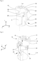
- the damping means 10 comprises a first and a second part 11, 12.
- the damping means 10 forms a cylindrical shell 15 with an axis coincident or substantially coincident with the main axis AP.
- the main axis AP preferably extends substantially vertically.
- the damping means 10 extends around an upper part 5 of the external envelope 4, in particular illustrated in the figure 8 . This is particularly the case when the element 8 is arranged in front of the upper part 5 of the accumulator 3 at the same level or substantially at the same level in the vertical direction as illustrated in the figure 2 .
- the damping means also has a cylindrical shape and thus surrounds the upper part 5, for example with a constant radial thickness over the entire circumference of the upper part.
- the first part 11 and the second part 12 extend around the upper part 5 of the accumulator 3.
- the first part 11 extends substantially over two thirds of the circumference (i.e. approximately 240 degrees) of the upper part 5 and the second part 12 extends substantially over the other third (i.e. approximately 120 degrees) of the circumference of the upper part 5.
- the first and second parts 11, 12 can be assembled with each other while being removable, separable, from each other.
- This particularity aims in particular to allow mounting of the damping means 10 at the level of the casing 4 of the accumulator 3, more precisely of the upper part 5, while the accumulator 3 is mounted on the body 30, or on the technical front face 31.
- the conduits 40 of the circuit 2 are already connected, connected, in particular to the accumulator 3, which is why a damping means 10 of conventional annular shape would not be suitable for mounting.
- the damping means comprises only one generally cylindrical part having an opening.
- a section of the damping means along a plane perpendicular to its axis has a general C shape.
- the opening of the C provides a passage for the ducts of the air conditioning circuit and allows the damping means to be mounted on the upper part of the casing while the circuit is already installed.
- the first part 11 comprises a first fixing means 13 and the second part 12 comprises a second fixing means 14.
- the first fixing means 13 is capable of cooperating with the second fixing means 14.
- the first fixing means 13 and the second fixing means 14 together form a sliding connection.
- the formed slide extends in the vertical or substantially vertical direction.
- the first and second fixing means 13, 14 each have a section along a plane perpendicular to the axis of the damping means intended to fit together, interlock, or complement each other.
- each section has a shape similar to a portion of puzzle pieces or in the general shape of a T.
- the first part 11 comprises a first fixing means 13 at each of its ends 111, 112 and the second part 12 comprises a second fixing means 14 at each of its ends 121, 122.
- the first fixing means 13 has a section along a plane perpendicular to the axis AP in the shape of an omega and the second fixing means 14 has a complementary section along a plane perpendicular to the axis AP, that is to say completing the internal shape of the omega.
- the second fastening means has a section, along a plane perpendicular to an axis coincident or substantially coincident with the main axis, in the shape of an omega and the first fastening means has a complementary section, along a plane perpendicular to an axis coincident or substantially coincident with the main axis, i.e. completing the internal shape of the omega.
- the first fastening means has a section in the shape of a male dovetail and the second fastening means has a complementary section in the shape of a female dovetail.
- the first fastening means has a section in the shape of a female dovetail and the second fastening means has a complementary section in the shape of a male dovetail.
- the first part 11 includes a first recess 17 or lug extending projecting from each end 111, 112 of the first part 11.
- the second part 12 comprises a second recess 18 or notch or recess at each of its ends 121, 122.
- the first recess 17 and the second recess 18 are arranged so as to complement each other when they are in contact with each other.
- the recesses 17, 18 are in contact with each other or substantially in contact with each other so that the general shape of the damping means is cylindrical.
- the function of the recesses 17, 18 is to ensure blocking, a stop, an end of travel of the first part 11 relative to the second part 12 during sliding, translation along the slide created by the fixing means 13, 14.
- each first recess 17 comprises a projection 171 of the type of stud or cylindrical outgrowth extending upwards.
- each second recess 18 comprises a cavity 181 of the cylindrical hollow type extending upwards.
- this translation is done in the vertical or substantially vertical direction, preferably from top to bottom.
- the first projection-type recess 17 is provided at the bottom of the first part 11 so as to stop the travel of the second part 12 relative to the first part 11 along the slide 13, 14.
- the recess 18 is then also provided at the bottom of the second Part 12.
- the fixing means 13, 14 forming a slide do not extend over the entire height H of the first and second parts 11, 12 measured parallel to the axis of the cylindrical protective shell 15 thus formed, but over only a portion of the order of 30 percent of this height, or even less.
- the thickness E of the damping means 10 measured radially relative to the main axis AP is between 10 mm and 25 mm, for example of the order of 17 mm.
- the damping means 10 is made of expanded polypropylene.
- the damping means 10 is made of polystyrene.
- the density of the material is between 45 grams per liter and 200 grams per liter, preferably between 70 grams per liter and 90 grams per liter.
- the arrangement 9 comprises the body 30 of the vehicle, and/or the technical front face 31.
- the arrangement 9 comprises at least one air conditioning duct 40 connected to the accumulator 3.
- the arrangement 9 further comprises a support 20 for fixing the accumulator 3 on the body 30.
- the support 20 creates, forms, offers a stop 25 for the damping means 10. More precisely, preferably the support 20 creates a stop for the first part 11, that is to say the part mounted first around the accumulator 3.
- the end of travel of the sliding connection between the first part 11 and the second part 12 that is to say the end of the translation between the means 13, 14 in the direction T (see figure 7 ), is ensured by contacts between the recesses 17, 18.
- a part 25 of the support 20 creates a stop for the end of travel when mounting the second part 12 along the first part 11.
- the installation of the damping means 10, in particular in the vertical direction, that is to say in the direction T is facilitated by contact of at least one part 11, 12, or even both, with the support 20, in particular the part 25.
- the part 25 is of the collar type coming to encircle, surround the external casing 4 of the accumulator 3 to be protected.
- the accumulator 3 or the external casing 4 of the accumulator comprises a bulge 19, a protrusion, a border, extending at the upper end of the accumulator, preferably over the entire circumference of the upper part 5.
- This bulge 19 creates a sort of stop ring preventing the second part 12 from being disengaged from the first part.
- the bulge 19 creates a stop preventing a translation, in the opposite direction to the direction T, so as to prevent the two parts 11, 12 from being dismantled, from being disengaged from each other in an untimely manner.
- the first part 11 comprises a notch 16.
- this notch 16 acts as a stop, preferably an end of travel in the vertical direction, for the placement of the first part 11 relative to the support 20.
- the cooperation of the support 20 in the notch 16 blocks any pivoting of the first part 11 (and therefore of the damping means) relative to the external casing 4 of the accumulator and/or any pivoting of the first part 11 (and therefore of the damping means) relative to the support 20.
- the support 20 comprises a base 23 extending vertically or substantially vertically.
- the support 20 is fixed to the body 30 and/or to the technical front face 31 by at least one fixing means 21.
- the fastening means 21 is a screw or a threaded rod extending from the base 23.
- two fastening means 21 are provided.
- each fastening means 21 sandwiches the support 20, in particular the base 23, between the fastening means 21, for example a screw head and the body 30 and/or the technical front face 31. More preferably, as illustrated in the figure 5 , each fastening means 21 passes through a groove 22 formed in the support 20, in particular in the base 23.
- each groove 22 extends substantially horizontally, in the longitudinal direction, and opens out towards the front.
- each groove 22 is an opening extending substantially in a transverse and longitudinal plane.
- a step is carried out to provide the body 30 (preferably equipped with the technical front face 31), the support 20, the accumulator 3, the air conditioning duct(s) 40, and the damping means 10.
- a step of mounting the accumulator 3 on the support 20 is carried out before mounting the support 20 on the body 30, in particular via the screws 21 as described previously.
- a step of connecting the air conditioning duct(s) 40 to the accumulator 3 is then carried out. Note that this step of connecting the air conditioning duct(s) 40 to the accumulator 3 can be carried out prior to the step of fixing the accumulator to the support and/or prior to the step of fixing the support to the body.
- a step of mounting the damping means 10 at the level of the accumulator is carried out.
- the first part 11 is first mounted.
- the first part 11 is a cylindrical portion, for example extending over approximately 240 degrees around an axis coincident with the main axis AP, i.e. an overall C-shaped section.
- the first part 11 is positioned so that the conduit(s) are located in the cavity of the C and a translation of the first part 11 is carried out along the upper part 5 of the external casing 4.
- the external diameter of the upper part 5 is less than the internal diameter of the first part 11.
- the internal diameter of the first part 11 is just greater than, or equal to or just less than the external diameter of the bulge 19.
- a slight bending of the C shape of the first part 11 allows it to be threaded around the bulge 11 so that the diameter of the upper part 5 can have a diameter equal to the internal diameter of the first part 11.
- the first part 11 is translated until it arrives in abutment against the base 23 at the level of the notch 16 and/or until the first part 11 comes into contact with the stop 25 of the support 20 as illustrated in the figure 4 in particular.
- the second part 12 is inserted onto the first part 11 so as to surround the upper part 5 of the external casing 4 of the accumulator 3.
- the second part 12 is a cylindrical portion, for example extending over approximately 120 degrees around an axis coincident with the main axis AP, i.e. an overall arc-shaped section. More precisely, a translation is carried out, in the direction T (preferably vertical) illustrated in the figure 7 , of the second part 12 along the first part 11. More precisely, as seen previously, a means 13 at each end of the first part 11 having a C-shaped section cooperates with a means 14 at each end of the second part 12 having an arc-shaped section to generate a sliding connection in the direction T.
- a clearance between the means 13, 14 is provided to facilitate the assembly by sliding without a buttressing-type phenomenon.
- clearance is necessary to "pass" the bulge 19 during the translation.
- the material chosen for the parts 11, 12 is sufficiently rigid to prevent each part from twisting, bending, buckling during the translation, in particular in the event of an insertion force, which would be detrimental to easy assembly.
- the translation is extended until the notches 18 come into contact with the projections 17.
- this end of translation travel is also materialized by the contact or substantially the contact of the second part 12 against the stop 25 of the support 20, as illustrated in the figure 3 .
- the bulge 19 prevents reverse sliding of the parts 11, 12 and provides safety to the means 10 assembled on the accumulator 3.
- the solution makes it possible to maintain the integrity of the accumulator in the event of a small front impact in the case of a vehicle chassis with a small front overhang, in particular not including a shock absorber also called a "crash box" in Anglo-Saxon terms, and consequently in the case of a cramped engine compartment, and this despite the fact that the accumulator 3 of the air conditioning circuit 2 is arranged at the front of the engine compartment.
- the solution allows it to be installed in the front area which is particularly exposed in the event of a front impact. Thanks to the solution, the accumulator is protected so well that it is not necessary to change it in the event of an impact. This results in savings, since an accumulator is expensive to purchase and its replacement is time-consuming and tedious, particularly because it is part of the air conditioning circuit.
- the solution offers protection for the air conditioning dehydrator bottle 3. This results in a better rating by a rating agency in the event of a shock and therefore a lower insurance amount.
- the solution is simple, easy and quick to install.
- the additional cost is very low, which is desirable, especially since this function is not visible to the customer/user of the vehicle.
- the solution does not require any modification of the vehicle, the damping means being added, if necessary, during assembly of the vehicle, or even as a retrofit if necessary.
- the damping means 10 remains removable if necessary, easily, preferably without tools, by sliding the second part 12 upwards, after having passed the hard point created by the bulge 19 present on the bottle 4, then sliding the first part 11.
- the protection is of the foam part type, relatively dense, in two parts and two T-shaped counter-forms to fit into each other, creating a circular, cylindrical, shell shape 15.
- the positioning in the vertical direction of the protector 10 is ensured by contact of the protector against the support 20, for example at the level of the notch 16 provided on the part 11.
- the protection 10 is added to the bottle 3 already fixed on its support 20.
- a recoil of the accumulator may be sought in the event of an impact, in order to maximize the damping.
- This recoil is for example permitted by the presence of at least one stud, preferably two filtration studs 24 or diabolos or Silentbloc (Registered trademark), for example comprising rubber (see figures 4 And 6 ).
- pads 24 improve, where appropriate, the acoustics of the accumulator/support assembly. The deformation provided by this or these pads 24 then allows the accumulator to recoil during an impact.
- the recoil of the accumulator is advantageously favored.
- a breakable connection for example with a weakness in the support, is provided.
- the grooves or openings 22 of the support 20 offer a possibility of moving the dehydrator 3 back relative to the body within the engine compartment if necessary, in the event of a front impact. More precisely, the grooves 22 allow the screws 21 to escape, that is to say to allow the support to slide backwards in the event of a front impact, especially in case of contact of element 8 ( figure 2 ) against protection 10.
- the pipes or conduits 40 of the air conditioning system or circuit are connected to the accumulator while having flexible lengths, and/or “slack”, and/or the conduits are shaped so as to be able to be bent.
- the movement of the accumulator, in particular its recoil does not create any incipient breakage, breakage, or marking on these conduits 40 likely to cause a malfunction of the air conditioning or even a leak in the air conditioning circuit.
- the density in particular in the case of expanded polypropylene type material, is of the order of 80g/l.
- such a density aims to offer protection 10 that is not very compressible. In the event of an impact, recoil is favored and/or complements a deformation of the damping means.
- the damping means 10 prevents plastic deformation of the accumulator in the event of a small front impact in particular. Repairs following a front impact are then reduced, in particular by avoiding the purchase of a new accumulator and the labor to replace it.
- the amount of insurance for a vehicle equipped with such an arrangement is reduced, which is advantageous for the owner of such a vehicle and may possibly motivate his act of purchase, in particular in the event of the purchase of numerous vehicles or a fleet thus equipped.
- the solution is economical, the manufacture of the damping means being inexpensive.
- the solution therefore achieves the desired objective of protecting the air conditioning accumulator in the event of an impact and has the advantage of be able to be adapted to another motorized vehicle, for example a bus or a truck.
Landscapes
- Engineering & Computer Science (AREA)
- Physics & Mathematics (AREA)
- Mechanical Engineering (AREA)
- Thermal Sciences (AREA)
- Chemical & Material Sciences (AREA)
- Analytical Chemistry (AREA)
- Power Engineering (AREA)
- General Engineering & Computer Science (AREA)
- Vibration Dampers (AREA)
- Air-Conditioning For Vehicles (AREA)
Applications Claiming Priority (1)
| Application Number | Priority Date | Filing Date | Title |
|---|---|---|---|
| FR2307535A FR3151006B1 (fr) | 2023-07-13 | 2023-07-13 | Agencement pour véhicule comprenant un accumulateur de climatisation et un moyen d’amortissement de l’accumulateur. |
Publications (2)
| Publication Number | Publication Date |
|---|---|
| EP4491423A2 true EP4491423A2 (de) | 2025-01-15 |
| EP4491423A3 EP4491423A3 (de) | 2025-04-09 |
Family
ID=88778781
Family Applications (1)
| Application Number | Title | Priority Date | Filing Date |
|---|---|---|---|
| EP24187801.6A Pending EP4491423A3 (de) | 2023-07-13 | 2024-07-10 | Anordnung für ein fahrzeug mit einem klimaspeicher und einem mittel zur dämpfung des akkumulators |
Country Status (2)
| Country | Link |
|---|---|
| EP (1) | EP4491423A3 (de) |
| FR (1) | FR3151006B1 (de) |
Family Cites Families (5)
| Publication number | Priority date | Publication date | Assignee | Title |
|---|---|---|---|---|
| US6378327B1 (en) * | 1999-09-30 | 2002-04-30 | Visteon Global Technologies, Inc. | Accumulator insulator bracket |
| JP2007055543A (ja) * | 2005-08-26 | 2007-03-08 | Kojima Press Co Ltd | 車両用歩行者保護装置 |
| KR20120044853A (ko) * | 2010-10-28 | 2012-05-08 | 현대자동차주식회사 | 플라스틱 복합재를 이용한 전기자동차용 배터리팩 케이스 어셈블리 |
| US9381790B2 (en) * | 2012-07-09 | 2016-07-05 | Nissan Motor Co., Ltd. | Air conditioning device for vehicle |
| JP2018103842A (ja) * | 2016-12-27 | 2018-07-05 | 本田技研工業株式会社 | 車両用空調装置のアキュムレータの取付部構造 |
-
2023
- 2023-07-13 FR FR2307535A patent/FR3151006B1/fr active Active
-
2024
- 2024-07-10 EP EP24187801.6A patent/EP4491423A3/de active Pending
Also Published As
| Publication number | Publication date |
|---|---|
| FR3151006A1 (fr) | 2025-01-17 |
| EP4491423A3 (de) | 2025-04-09 |
| FR3151006B1 (fr) | 2025-11-14 |
Similar Documents
| Publication | Publication Date | Title |
|---|---|---|
| FR3099459A1 (fr) | Déflecteur aérodynamique destiné à être fixé contre le soubassement de caisse d’un véhicule | |
| WO2019043313A1 (fr) | Ensemble pare-chocs pour vehicule automobile | |
| FR2900605A1 (fr) | Procede de fabrication d'un mecanisme d'articulation pour siege de vehicule, mecanisme d'articulation fabrique selon un tel procede et siege de vehicule comprenant un tel mecanisme d'articulation | |
| FR2890361A1 (fr) | Insert pour caisse de vehicule automobile | |
| EP4491423A2 (de) | Anordnung für ein fahrzeug mit einem klimaspeicher und einem mittel zur dämpfung des akkumulators | |
| EP3390165B1 (de) | Trimmvorrichtung mit eingebautem airbag für ein kraftfahrzeug | |
| EP4323238B1 (de) | Anordnung mit einer schutzvorrichtung für einen sicherungskasten eines fahrzeugs | |
| EP2736793B1 (de) | Kopfmodul für ein kraftfahrzeug | |
| FR3099907A1 (fr) | Déflecteur aérodynamique arrière pour véhicule automobile | |
| FR2895959A1 (fr) | Dispositif de protection d'une goulotte de remplissage d'un reservoir de carburant d'un vehicule automobile | |
| WO2020099754A1 (fr) | Support monobloc de fixation d'un enrouleur de ceinture de securite sur une doublure de custode d'un vehicule automobile. | |
| EP2090476B1 (de) | Struktur eines Fahrzeugs mit Anpassung der Befestigung eines Kindersitzes | |
| EP2606219B1 (de) | Haltevorrichtung einer stop-start vorrichtung auf einer fahrzeugkarosserie und zusammenbauverfahren der gleichen. | |
| WO2020157414A1 (fr) | Vehicule comprenant un support d'enjoliveur de vitre assemble par clinchage | |
| FR2868371A1 (fr) | Ensemble de montage d'une barre de toit longitudinale sur un toit d'un vehicule automobile | |
| EP2493748B1 (de) | Armaturenbrettstruktur für ein motorfahrzeug und herstellungsverfahren dafür | |
| EP3515738B1 (de) | Gehäusesystem für traktionsbatterien eines hybrid- oder elektrofahrzeuges | |
| FR3148778A1 (fr) | Plaque de protection de train arrière de véhicule terrestre à fonction de pré-maintien | |
| FR3014817A1 (fr) | Traverse pour planche de bord avec support lateral a structure mixte metallo-plastique | |
| FR3029162A1 (fr) | Agencement pour vehicule automobile muni d'une entretoise ajustable disposee entre deux elements de structure | |
| FR3134359A1 (fr) | Patte de fixation d’un projecteur de véhicule automobile | |
| EP4377159A1 (de) | Kraftfahrzeug mit einer einen frontstossfänger aufweisenden karosseriestruktur | |
| FR2928106A1 (fr) | Dispositif de securite pour une porte de vehicule | |
| FR3120578A1 (fr) | Support d’un chargeur de batterie électrique d’un véhicule automobile | |
| FR3105155A1 (fr) | Support de retenue provisoire d’un brin libre de colonne de direction |
Legal Events
| Date | Code | Title | Description |
|---|---|---|---|
| PUAI | Public reference made under article 153(3) epc to a published international application that has entered the european phase |
Free format text: ORIGINAL CODE: 0009012 |
|
| STAA | Information on the status of an ep patent application or granted ep patent |
Free format text: STATUS: THE APPLICATION HAS BEEN PUBLISHED |
|
| AK | Designated contracting states |
Kind code of ref document: A2 Designated state(s): AL AT BE BG CH CY CZ DE DK EE ES FI FR GB GR HR HU IE IS IT LI LT LU LV MC ME MK MT NL NO PL PT RO RS SE SI SK SM TR |
|
| PUAL | Search report despatched |
Free format text: ORIGINAL CODE: 0009013 |
|
| AK | Designated contracting states |
Kind code of ref document: A3 Designated state(s): AL AT BE BG CH CY CZ DE DK EE ES FI FR GB GR HR HU IE IS IT LI LT LU LV MC ME MK MT NL NO PL PT RO RS SE SI SK SM TR |
|
| RIC1 | Information provided on ipc code assigned before grant |
Ipc: F25B 43/00 20060101ALI20250304BHEP Ipc: B60H 1/32 20060101AFI20250304BHEP |
|
| STAA | Information on the status of an ep patent application or granted ep patent |
Free format text: STATUS: REQUEST FOR EXAMINATION WAS MADE |
|
| 17P | Request for examination filed |
Effective date: 20250618 |