EP4491352A1 - Robot control method and robot - Google Patents
Robot control method and robot Download PDFInfo
- Publication number
- EP4491352A1 EP4491352A1 EP23766851.2A EP23766851A EP4491352A1 EP 4491352 A1 EP4491352 A1 EP 4491352A1 EP 23766851 A EP23766851 A EP 23766851A EP 4491352 A1 EP4491352 A1 EP 4491352A1
- Authority
- EP
- European Patent Office
- Prior art keywords
- end effector
- robot
- plate
- shaped object
- robot arm
- Prior art date
- Legal status (The legal status is an assumption and is not a legal conclusion. Google has not performed a legal analysis and makes no representation as to the accuracy of the status listed.)
- Pending
Links
Images








Classifications
-
- B—PERFORMING OPERATIONS; TRANSPORTING
- B25—HAND TOOLS; PORTABLE POWER-DRIVEN TOOLS; MANIPULATORS
- B25J—MANIPULATORS; CHAMBERS PROVIDED WITH MANIPULATION DEVICES
- B25J9/00—Program-controlled manipulators
- B25J9/16—Program controls
- B25J9/1679—Program controls characterised by the tasks executed
- B25J9/1682—Dual arm manipulator; Coordination of several manipulators
-
- B—PERFORMING OPERATIONS; TRANSPORTING
- B25—HAND TOOLS; PORTABLE POWER-DRIVEN TOOLS; MANIPULATORS
- B25J—MANIPULATORS; CHAMBERS PROVIDED WITH MANIPULATION DEVICES
- B25J13/00—Controls for manipulators
-
- B—PERFORMING OPERATIONS; TRANSPORTING
- B25—HAND TOOLS; PORTABLE POWER-DRIVEN TOOLS; MANIPULATORS
- B25J—MANIPULATORS; CHAMBERS PROVIDED WITH MANIPULATION DEVICES
- B25J13/00—Controls for manipulators
- B25J13/08—Controls for manipulators by means of sensing devices, e.g. viewing or touching devices
-
- B—PERFORMING OPERATIONS; TRANSPORTING
- B25—HAND TOOLS; PORTABLE POWER-DRIVEN TOOLS; MANIPULATORS
- B25J—MANIPULATORS; CHAMBERS PROVIDED WITH MANIPULATION DEVICES
- B25J15/00—Gripping heads and other end effectors
- B25J15/0033—Gripping heads and other end effectors with gripping surfaces having special shapes
-
- B—PERFORMING OPERATIONS; TRANSPORTING
- B25—HAND TOOLS; PORTABLE POWER-DRIVEN TOOLS; MANIPULATORS
- B25J—MANIPULATORS; CHAMBERS PROVIDED WITH MANIPULATION DEVICES
- B25J5/00—Manipulators mounted on wheels or on carriages
- B25J5/007—Manipulators mounted on wheels or on carriages mounted on wheels
-
- B—PERFORMING OPERATIONS; TRANSPORTING
- B25—HAND TOOLS; PORTABLE POWER-DRIVEN TOOLS; MANIPULATORS
- B25J—MANIPULATORS; CHAMBERS PROVIDED WITH MANIPULATION DEVICES
- B25J9/00—Program-controlled manipulators
- B25J9/0084—Program-controlled manipulators comprising a plurality of manipulators
-
- B—PERFORMING OPERATIONS; TRANSPORTING
- B25—HAND TOOLS; PORTABLE POWER-DRIVEN TOOLS; MANIPULATORS
- B25J—MANIPULATORS; CHAMBERS PROVIDED WITH MANIPULATION DEVICES
- B25J9/00—Program-controlled manipulators
- B25J9/0084—Program-controlled manipulators comprising a plurality of manipulators
- B25J9/0087—Dual arms
-
- B—PERFORMING OPERATIONS; TRANSPORTING
- B25—HAND TOOLS; PORTABLE POWER-DRIVEN TOOLS; MANIPULATORS
- B25J—MANIPULATORS; CHAMBERS PROVIDED WITH MANIPULATION DEVICES
- B25J9/00—Program-controlled manipulators
- B25J9/16—Program controls
- B25J9/1615—Program controls characterised by special kind of manipulator, e.g. planar, scara, gantry, cantilever, space, closed chain, passive/active joints and tendon driven manipulators
- B25J9/162—Mobile manipulator, movable base with manipulator arm mounted on it
-
- G—PHYSICS
- G05—CONTROLLING; REGULATING
- G05B—CONTROL OR REGULATING SYSTEMS IN GENERAL; FUNCTIONAL ELEMENTS OF SUCH SYSTEMS; MONITORING OR TESTING ARRANGEMENTS FOR SUCH SYSTEMS OR ELEMENTS
- G05B2219/00—Program-control systems
- G05B2219/30—Nc systems
- G05B2219/39—Robotics, robotics to robotics hand
- G05B2219/39109—Dual arm, multiarm manipulation, object handled in cooperation
-
- G—PHYSICS
- G05—CONTROLLING; REGULATING
- G05B—CONTROL OR REGULATING SYSTEMS IN GENERAL; FUNCTIONAL ELEMENTS OF SUCH SYSTEMS; MONITORING OR TESTING ARRANGEMENTS FOR SUCH SYSTEMS OR ELEMENTS
- G05B2219/00—Program-control systems
- G05B2219/30—Nc systems
- G05B2219/39—Robotics, robotics to robotics hand
- G05B2219/39121—Two manipulators operate on same object
-
- G—PHYSICS
- G05—CONTROLLING; REGULATING
- G05B—CONTROL OR REGULATING SYSTEMS IN GENERAL; FUNCTIONAL ELEMENTS OF SUCH SYSTEMS; MONITORING OR TESTING ARRANGEMENTS FOR SUCH SYSTEMS OR ELEMENTS
- G05B2219/00—Program-control systems
- G05B2219/30—Nc systems
- G05B2219/40—Robotics, robotics mapping to robotics vision
- G05B2219/40411—Robot assists human in non-industrial environment like home or office
Definitions
- the present disclosure relates to a method of controlling a robot, and a robot.
- JP2018-008820A discloses a robot including a pair of robot arms.
- Each of the robot arms includes a hand portion having a clamping portion.
- the clamping portion includes an L-shaped plate portion. The robot grips and transfers a tray by inserting the clamping portions of the pair of robot arms under the tray from both sides of the tray and laterally sandwiching the tray using the two clamping portions.
- the robot disclosed in JP2018-008820A needs to use two robot arms to grip and transfer a plate-shaped object such as a tray.
- the present disclosure provides a robot and a method of controlling a robot that reduce operations of robot arms related to transferring of a plate-shaped object.
- a control method of a robot includes: causing a first robot arm provided in the robot and a second robot arm provided in the robot to move a first end effector of the first robot arm and a second end effector of the second robot arm such that the first end effector and the second end effector are arranged on both sides of a placed plate-shaped object; causing the first robot arm to move the first end effector toward a first end portion of the plate-shaped object, and causing the first end effector to operate so as to grip the first end portion; and causing the first robot arm to move the first end effector toward a destination position, and causing the first end effector to place the plate-shaped object at the destination position.
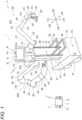
- FIG. 1 is a diagram illustrating the example of the configuration of the robot system A according to the embodiment.
- the robot system A includes a robot 1 and an input device 2.
- the input device 2 is arranged at a position away from the robot 1.
- the input device 2 receives input of a command, information, data, and the like by a user, and transmits the received command, information, data, and the like to the robot 1.
- the input device 2 receives a command, information, data, and the like from the robot 1.
- the user who uses the input device 2 may be a manager of the robot system A, an operator of the robot 1, a service provider via the robot system A, or a service receiver via the robot system A.
- the input device 2 includes a communication device 2a communicating with the robot 1, and a processing circuit including a processor P and a memory M.
- the communication between the communication device 2a and the robot 1 is a wireless communication, but may also be a wired communication or a combination of wired and wireless communications. Any wired communication or wireless communication may be used.
- the communication device 2a and the robot 1 may directly or indirectly perform the wireless communication. In the indirect wireless communication, the communication device 2a and the robot 1 may be connected to a communication network via a wired communication or a wireless communication, and may communicate with each other via the communication network.
- the communication device 2a may include a communication circuit.
- the communication network is not particularly limited, and may include, for example, a local area network (LAN), a wide area network (WAN), the Internet, or a combination of two or more thereof.
- the communication network may use near field communication such as Bluetooth (registered trademark) and ZigBee (registered trademark), a network dedicated line, a communication carrier dedicated line, a public switched telephone network (PSTN), a mobile communication network, an Internet network, satellite communication, or a combination of two or more thereof.
- PSTN public switched telephone network
- the mobile communication network may use a fourth-generation mobile communication system, a fifth-generation mobile communication system, and the like.
- the communication network can include one or a plurality of networks.
- the input device 2 may include one or more of a computer such as a personal computer, a smart device such as a smartphone and a tablet computer, a personal digital assistant, a game terminal, a known teaching device such as a teach pendant used for a teaching operation to a robot, a known operation device of a robot, other operation devices, other terminal devices, a device using the above, and a device in which the above is improved.
- the input device 2 may be a dedicated device designed for the robot 1, and may be a general-purpose device available in a general market. When the input device 2 is a general-purpose device, a function of the input device 2 may be implemented by installing dedicated software.
- the robot 1 performs an operation of providing a service to the user.
- the robot 1 can be used in various services such as care, medical, cleaning, security, guidance, rescue, cooking, commodity provision, and physical distribution.
- the robot 1 includes a moving device 100, one or more robot arms 200, a support 500, and a control device 600.
- the robot 1 includes a secondary battery module 10, a power supply circuit 20, a communication device 30, an imaging device 40, a sensor 50, and a presentation device 60.
- a robot arm capable of functioning as an industrial robot arm is used as the robot arm 200.
- the imaging device 40 and the presentation device 60 may function as devices for communicating with the user around the robot 1.
- the imaging device 40 includes imaging devices 41a to 41f, and detects various information around the robot 1.
- Each of the imaging devices 41a to 41f includes a camera that captures a digital image.
- One or more of the imaging devices 41a to 41f may include a three-dimensional camera capable of detecting a distance to a subject. Examples of the three-dimensional camera may include a stereo camera, a time-of-flight-camera (TOF camera), a pattern light projection camera such as fringe projection, and a camera using a light-section method.
- Each of the imaging devices 41a to 41f outputs data of the captured image to the control device 600.
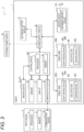
- Examples of the components as control targets by the control device 600 may include the movement driving devices 141 and 142, the joint driving devices MA1 to MA6 and MB1 to MB6, the driving devices ME1 and ME2 of the end effectors 300 and 400, the power supply circuit 20, the communication device 30, the imaging devices 41a to 41f, the sensor 50, the display 61, and the like, but not all of the above are required.
- the control device 600 includes the processing circuit including the processor P and the memory M.
- the control device 600 may be an electronic circuit board, an electronic control unit, a microcomputer, or other electronic devices.
- the processor P transmits and receives a command, information, data, and the like to and from other devices.
- the processor P inputs a signal from various devices and outputs a control signal to a control target.
- At least a part of a plurality of functions of the control device 600 and the input device 2 may be implemented by cooperation of the processor P and the memory M.
- the processor P and the memory M including the RAM and the ROM form a computer system.
- the computer system may implement the above functions by the processor P executing a program recorded in the ROM using the RAM as a work area.
- the processor P may include, for example, one or more of a central processing unit (CPU), a micro processing unit (MPU), a graphics processing unit (GPU), a microprocessor, a processor core, a multiprocessor, an application-specific integrated circuit (ASIC), a field programmable gate array (FPGA), and a reconfigurable processor.
- the processor P may implement a process by a logic circuit or a dedicated circuit which is a hardware circuit formed in, for example, an integrated circuit such as an integrated circuit (IC) chip and a large scale integration (LSI).
- the functions of the control device 600 and the input device 2 may be implemented by an integrated circuit that is individually integrated into one chip, and may be implemented by an integrated circuit that is integrated into one chip so as to include a part or all of the functions.
- FIGS. 4 and 5 are side views illustrating examples of components in two different states of the first end effector 300 of the robot 1 in FIG. 1 .
- FIGS. 4 and 5 show the inside of a main body 310 of the first end effector 300.
- the first end effector 300 has a structure suitable for holding a plate-shaped object PL.
- the first end effector 300 includes the main body 310, a first holding portion 320, a second holding portion 330, the driving device ME1, a drive shaft 340, and a driven shaft 350.
- the main body 310 includes a mechanical interface connected to the mechanical interface of the link LA6 or LB6 of the robot arm 200A or 200B.
- the driving device ME1, the drive shaft 340, and the driven shaft 350 are arranged in the main body 310.
- the drive shaft 340 is connected to the driving device ME1 so as to be rotationally driven by the driving device ME1.
- the driven shaft 350 is engaged with the drive shaft 340 by gears.
- a driven gear 351 rotating integrally with the driven shaft 350 is engaged with a drive gear 341 rotating integrally with the drive shaft 340.
- the driving device ME1 rotationally drives the driven shaft 350 via the drive shaft 340.
- the first holding portion 320 is fixed to the main body 310 in an immovable manner. At least a part of the first holding portion 320 may be integrated with the main body 310.
- the first holding portion 320 includes a base link 321 extending from the main body 310 in a direction D4A, and a tip end link 322 connected to a tip end of the base link 321.
- the base link 321 and the tip end link 322 may be integrated.
- the base link 321 may have a columnar or finger-like shape and function as a finger portion of the robot hand.
- directions D4A, D4B, D5A, D5B, D6A, and D6B illustrated in FIGS. 4 and 5 are directions relative to the first end effector 300.
- the direction D4A is a direction away from the main body 310
- the direction D4B is a direction opposite to the direction D4A.
- the directions D5A and D5B are directions opposite to each other, and are directions perpendicular to the directions D4A and D4B.
- the directions D6A and D6B are directions opposite to each other, and are directions that are perpendicular to the directions D4A and D4B and intersect the directions D5A and D5B.
- the directions D6A and D6B are directions perpendicular to the directions D5A and D5B.
- the tip end link 322 includes a recess 322a, and the recess 322a opens in the direction D4A and opens in the directions D5A and D5B.
- the tip end link 322 includes a base portion 322b connected to the base link 321, and clamping portions 322c and 322d arranged to face each other.
- the recess 322a is formed between the clamping portions 322c and 322d.
- the first clamping portion 322c extends from the base portion 322b in the direction D4A and the directions D5A and D5B.
- the first clamping portion 322c has a flat surface 322ca facing the second clamping portion 322d and oriented in the direction D6A.
- the widths of the first clamping portion 322c and the surface 322ca in the directions D5A and D5B are larger than the width of the base portion 322b.
- the first clamping portion 322c may have a plate shape.
- the second clamping portion 322d is arranged in the direction D6A with respect to the first clamping portion 322c.
- the second clamping portion 322d extends from the base portion 322b in the direction D4A and the directions D5A and D5B.
- the second clamping portion 322d protrudes toward the direction D4A with respect to the first clamping portion 322c.
- the second clamping portion 322d has flat surfaces 322da and 322db facing the first clamping portion 322c.
- the widths of the second clamping portion 322d and the surfaces 322da and 322db in the directions D5A and D5B may be larger than the width of the base portion 322b, and may be, for example, equal to the widths of the first clamping portion 322c and the surface 322ca in the directions D5A and D5B.
- the surface 322da is positioned in the direction D4A with respect to the surface 322db, and is oriented in the direction D6B.
- the surface 322da may be extend along the surface 322ca, and may be, for example, parallel to the surface 322ca.
- the surface 322db is inclined to approach the surface 322ca as advancing in the direction D4B.
- the recess 322a includes a shape that tapers toward the direction D6B as advancing in the direction D4B.
- the recess 322a has a triangular prism shape having a wedge-shaped cross section.
- end portions of the surfaces 322db and 322ca in the direction D4A are positioned at the same distance from the base portion 322b, and face each other in the directions D6A and D6B.
- the second clamping portion 322d has a plate shape bent at a bent portion 322dc as a boundary between the surfaces 322da and 322db. Accordingly, it is easy to insert the second clamping portion 322d into a gap between a surface on which the plate-shaped object PL is placed and the plate-shaped object PL. Further, even when an attitude of the end effector 300 with respect to the plate-shaped object PL is different from the attitude in FIG. 4 and the surface 322da has an angle so as not to be parallel to a surface of the plate-shaped object PL, it is easily to insert the plate-shaped object PL into the recess 322a.
- At least a part of the second clamping portion 322d may include a tapered shape such that the thickness thereof in the direction D6A decreases as advancing in the direction D4A.
- the plate-shaped object PL inserted into the recess 322a is in contact with the surface 322ca and one or both of the surfaces 322da and 322db, and is clamped by the clamping portions 322c and 322d. Accordingly, the plate-shaped object PL is held by the first holding portion 320.
- the second holding portion 330 is attached to the main body 310 in an operable manner.
- the second holding portion 330 is arranged in the direction D6B with respect to the first holding portion 320.
- the second holding portion 330 faces the first holding portion 320 in the direction D6A.
- the second holding portion 330 includes a link mechanism 331 connected to an end portion 310a of the main body 310 in the direction D4A, and a tip end link 332 connected to a tip end of the link mechanism 331.
- the end portion 310a may be positioned on a side opposite to the mechanical interface of the main body 310.
- the link mechanism 331 includes links 331a to 331e.
- the links 331a and 331b are pivotally connected to the main body 310 at respective proximal ends thereof, and extend along each other.
- a tip end of the link 331a is pivotally connected to an intermediate position of the link 331c.
- a tip end of the link 331b is pivotally connected to a proximal end of the link 331d.
- the links 331c and 331d are pivotally connected to the tip end link 332 at respective tip ends thereof, and extend along each other.
- a proximal end of the link 331c is pivotally connected to a pivoting member 352 that pivots integrally with the driven shaft 350.
- a connection portion between the link 331c and the pivoting member 352 is positioned in the direction D6A with respect to connection portions between the links 331a and 331b and the main body 310.
- a connection portion between the tip end of the link 331a and the link 331c is pivotally connected to one end of the link 331e.
- a connection portion between the tip end of the link 331b and the proximal end of the link 331d is pivotally connected to the other end of the link 331e.
- the link mechanism 331 has a structure including two parallel links connected to each other.
- the tip end link 332 extends toward the direction D6A as advancing in the direction D4A.
- the tip end link 332 extends toward the first holding portion 320.
- the tip end link 332 has a shape that tapers toward a tip end, and has, for example, a wedge-shaped or claw-shaped cross-sectional shape.
- the width of the tip end link 332 in the directions D5A and D5B is smaller than the widths of the clamping portions 322c and 322d in the directions D5A and D5B.
- a contact area in which the tip end link 332 can come into contact with the article is smaller than a contact area in which the clamping portions 322c and 322d can come into contact with the article.
- the first end effector 300 in the state illustrated in FIG. 4 , when the driving device ME1 rotationally drives the driven shaft 350 toward a direction R1 via the drive shaft 340, the first end effector 300 is in the state illustrated in FIG. 5 .
- the link mechanism 331 moves the tip end link 332 in parallel in the directions D4B and D6A. Accordingly, the tip end of the tip end link 332 approaches the second clamping portion 322d.
- the second holding portion 330 moves the tip end link 332 to approach or separate away from the second clamping portion 322d.
- the second holding portion 330 presses the plate-shaped object PL inserted into the recess 322a against the second clamping portion 322d by using the tip end link 332, thereby strengthening the holding of the plate-shaped object PL. That is, the first holding portion 320 and the second holding portion 330 grip the plate-shaped object PL.
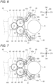
- FIGS. 6 and 7 are side views illustrating examples of components in two different states of the second end effector 400 of the robot 1 in FIG. 1 .
- FIGS. 6 and 7 show the inside of a main body 410 of the second end effector 400.
- the second end effector 400 includes the main body 410, a first holding portion 420, a second holding portion 430, the driving device ME2, a drive shaft 440, a first driven shaft 450, and a second driven shaft 460.
- the main body 410 includes a mechanical interface connected to the mechanical interface of the link LA6 or LB6 of the robot arm 200A or 200B.
- the driving device ME2, the drive shaft 440, and the driven shafts 450 and 460 are arranged in the main body 410.
- the drive shaft 440 is connected to the driving device ME2 so as to be rotationally driven by the driving device ME2.
- the first driven shaft 450 is engaged with the drive shaft 440 by gears
- the second driven shaft 460 is engaged with the first driven shaft 450 by gears.
- a driven gear 451 rotating integrally with the first driven shaft 450 is engaged with a drive gear 441 rotating integrally with the drive shaft 440.
- a driven gear 461 rotating integrally with the second driven shaft 460 is engaged with the driven gear 451.
- the driving device ME2 rotationally drives the driven shafts 450 and 460 in directions opposite to each other via the drive shaft 440.
- directions D7A, D7B, D8A, D8B, D9A, and D9B illustrated in FIGS. 6 and 7 are directions relative to the second end effector 400, and are defined similarly to the directions D4A, D4B, D5A, D5B, D6A, and D6B of the first end effector 300.
- the directions D7A and D7B respectively correspond to the directions D4A and D4B
- the directions D8A and D8B respectively correspond to the directions D5A and D5B
- the directions D9A and D9B respectively correspond to the directions D6A and D6B.
- the holding portions 420 and 430 are attached to an end portion 410a of the main body 410 in the direction D7A in an operable manner.
- the second holding portion 430 is arranged in the direction D9A with respect to the first holding portion 420.
- the second holding portion 430 faces the first holding portion 420 in the direction D9B.
- the end portion 410a may be positioned on a side opposite to the mechanical interface of the main body 410.
- the holding portions 420 and 430 include link mechanisms 421 and 431 connected to the end portion 410a, and tip end links 422 and 432 connected to tip ends of the link mechanisms 421 and 431, respectively.
- the link mechanisms 421 and 431 have structures similar to that of the link mechanism 331 of the first end effector 300. Although not limited to the following, in the present embodiment, the link mechanisms 421 and 431 have mutually symmetrical structures with respect to an axis extending in the directions D7A and D7B.
- a link 421a of the link mechanism 421 is pivotally connected to a pivoting member 452 that pivots integrally with the first driven shaft 450.
- a link 431a of the link mechanism 431 is pivotally connected to a pivoting member 462 that pivots integrally with the second driven shaft 460.
- the tip end links 422 and 432 include connection portions 422a and 432a connected to the link mechanisms 421 and 431, and tip end portions 422b and 432b, respectively.
- the tip end portions 422b and 432b are connected to the connection portions 422a and 432a in a slidable manner, respectively.
- Sliding directions of the tip end portions 422b and 432b are direction along a plane including the direction D7A and the direction D9A, and are directions intersecting the direction D7A and the direction D9A.
- Structures for sliding the tip end portions 422b and 432b may be any structure as long as a sliding operation can be achieved.
- one of the tip end portions 422b and 432b and one of the connection portions 422a and 432a may include a protrusion, and the other one thereof may include a recess such as a hole, for example, a slot, or a groove that receives the protrusion in a slidable manner.
- the tip end portion 422b When receiving a force in the direction D7B in a state of sliding toward the direction D7A with respect to the connection portion 422a, the tip end portion 422b may move toward the direction D9B while moving toward the direction D7B. When receiving a force in the direction D9B in the above state, the tip end portion 422b may move toward the direction D7B while moving toward the direction D9B. When receiving a force in the direction D7B in a state of sliding toward the direction D7A with respect to the connection portion 432a, the tip end portion 432b may move toward the direction D9A while moving toward the direction D7B.
- the tip end portion 422b When receiving a force in the direction D9A in the above state, the tip end portion 422b may move toward the direction D7B while moving toward the direction D9A.
- the tip end portions 422b and 432b are connected to the connection portions 422a and 432a, respectively, so as not to change the directions thereof with respect to the connection portions 422a and 432a.
- the tip end portions 422b and 432b may be pivotally connected to the connection portions 422a and 432a, respectively, and the directions thereof may be freely changed.
- Biasing members such as coil springs may be arranged in the connection portions 422a and 432a, and may bias the tip end portions 422b and 432b toward the direction D7A.
- the biasing member of the connection portion 422a absorbs an impact received by the holding portion 420 when the tip end portion 422b receives a force in the direction D7B or D9B from an object W.
- the biasing member of the connection portion 432a absorbs an impact received by the holding portion 430 when the tip end portion 432b receives a force in the direction D7B or D9A from the object W.
- the biasing members enable the holding portions 420 and 430 to stably grip the object W by sandwiching the object W by the tip end links 422 and 432 with an elastic force.
- the first driven shaft 450 rotationally drives the second driven shaft 460 in a direction R2 opposite to the direction R1.
- the second end effector 400 is in the state illustrated in FIG. 7 .
- the link mechanism 421 moves the tip end link 422 in parallel in the directions D7B and D9A.
- the link mechanism 431 moves the tip end link 432 in parallel in the directions D7B and D9B. Accordingly, the second end effector 400 can sandwich and grip the object W by the tip end links 422 and 432.
- FIG. 8 is a flowchart illustrating the example of the first operation of the robot system A according to the embodiment.
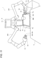
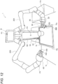
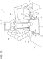
- FIGS. 9 to 13 are perspective views each illustrating an example of a state of the robot 1 included in the first operation.
- the robot 1 uses the robot arms 200A and 200B by autonomous driving to provide food service to the user by using a tray TR which is an example of the plate-shaped object.
- step S101 the input device 2 receives a food service command for commanding the food service by the tray TR to the user using a table TA.
- the input device 2 transmits the food service command and position information on the table TA to the robot 1.
- the tray TR on which a vessel containing a beverage as an example of food is placed is arranged on the shelves 521 of the rack 520 of the robot 1 by a service provider.
- step S102 the control device 600 activates an autonomous driving program for a food service operation of the robot 1, and executes a subsequent control of the robot 1 according to the autonomous driving program.
- the autonomous driving program for the food service operation is a program for causing the robot 1 to autonomously transfer the tray TR from a starting point to a destination point and provide the food service by the tray TR at the destination point.
- step S103 the control device 600 moves the robot 1 to the table TA while operating the moving device 100 and causing the imaging device 40 to capture an image.
- the control device 600 moves the robot 1 while avoiding an obstacle by using map information stored in the memory M, a result of the image process on image data acquired by the imaging device 40, and the like.
- step S104 when the robot 1 arrives at the front of the table TA, the control device 600 causes the imaging device 40 to capture images of the table TA and the tray TR.
- the control device 600 performs the image process on the image data acquired by the imaging device 40 so as to detect a position, a shape, and a size of the tray TR on the rack 520 and a position, a shape, and a size of the table TA. Further, the control device 600 determines a destination position on an edge TRa of the tray TR to be gripped by the first end effector 300 and a destination position on the table TA in which the tray TR is to be arranged.
- the control device 600 causes the robot 1 to operate while causing the imaging device 40 to capture an image. Further, the control device 600 adjusts positions and attitudes of the first end effector 300, the second end effector 400, and the tray TR by using a result of the process on the image data acquired by the imaging device 40 and the like.
- step S105 the control device 600 causes the robot arm 200A to move the first end effector 300 such that the second clamping portion 322d of the first end effector 300 is positioned on a lateral side of and in the vicinity of the destination position on the edge TRa of the tray TR.
- the control device 600 causes the robot arm 200B to move the second end effector 400 such that the tip end portions 422b and 432b of the second end effector 400 are positioned on a lateral side of and in the vicinity of an edge TRb of the tray TR opposite to the edge TRa.
- the second clamping portion 322d and the tip end portions 422b and 432b may be arranged at positions opposed to each other with the tray TR sandwiched therebetween.
- the order of movement of the end effectors 300 and 400 may be any order.
- step S106 the control device 600 causes the robot arm 200A to move the first end effector 300 such that the second clamping portion 322d of the first end effector 300 is inserted under the tray TR.
- the control device 600 adjusts the attitude of the first end effector 300 such that the surface 322da of the second clamping portion 322d is horizontal under the tray TR.
- the control device 600 causes the robot arm 200A to move the first end effector 300 until the edge TRa of the tray TR is inserted into the recess 322a of the first holding portion 320. At this time, the tip end portions 422b and 432b of the second end effector 400 abut the edge TRb of the tray TR to restrain sliding of the tray TR.
- the control device 600 may cause the robot arm 200B to move the second end effector 400 such that the tip end portions 422b and 432b approach the edge TRb.
- the first end effector 300 is in the state illustrated in FIG. 4 .
- the control device 600 may detect the insertion of the edge TRa into the recess 322a by using the result of the process on the image data acquired by the imaging device 40, loads of the joint driving devices of one or both of the robot arms 200A and 200B, a detection result of one or both of the force sensors arranged at the connection portions between the end effectors 300 and 400 and the robot arms 200A and 200B, or two or more thereof.
- step S107 the control device 600 operates the second holding portion 330 of the first end effector 300, and causes the second clamping portion 322d and the second holding portion 330 to grip the tray TR. Accordingly, the first end effector 300 is in the state illustrated in FIG. 5 .
- step S108 the control device 600 causes the robot arm 200A to move the first end effector 300 such that the tray TR rises and moves to the destination position on the table TA.
- the control device 600 causes the robot arm 200B to move the second end effector 400 such that the tip end portions 422b and 432b separate from the edge TRb of the tray TR.
- the control device 600 adjusts a movement path of the tray TR by using the result of the process on the image data acquired by the imaging device 40 and the like.
- the order of movement of the end effectors 300 and 400 may be any order.
- step S109 the control device 600 causes the robot arm 200A to move the first end effector 300 such that the tray TR moves downward while the tray TR is slightly inclined so that the edge TRb is positioned below the edge TRa.
- the control device 600 stops the movement of the first end effector 300.
- the control device 600 may detect the contact between the edge TRb and the table TA by using the result of the process on the image data acquired by the imaging device 40, the loads of the joint driving devices of the robot arm 200A, the detection result of the force sensor arranged at the connection portion between the first end effector 300 and the robot arm 200A, or two or more thereof.
- step S110 the control device 600 causes the robot arm 200B to move the second end effector 400 such that the tip end portion 422b or 432b of the second end effector 400 comes into contact with an upper surface of the tray TR near the edge TRb and presses the tray TR downward toward the surface of the table TA.
- the control device 600 may detect a pressing force of the second end effector 400 and adjust the pressing force by using the loads of the joint driving devices of the robot arm 200B, the detection result of the force sensor arranged at the connection portion between the second end effector 400 and the robot arm 200B, or a combination thereof.
- step Sill the control device 600 causes the robot arm 200A to move the first end effector 300 such that the second clamping portion 322d of the first end effector 300 is pulled out under the tray TR.
- the control device 600 causes the robot arm 200B to move the second end effector 400 such that the tip end portions 422b and 432b separate from the tray TR.
- step S112 the control device 600 operates the moving device 100 so as to move the robot 1 to a predetermined standby position or a place specified via the input device 2.
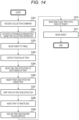
- FIG. 14 is a flowchart illustrating the example of the second operation of the robot system A according to the embodiment.
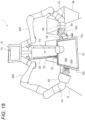
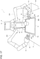
- FIGS. 15 to 18 are perspective views each illustrating an example of a state of the robot 1 included in the second operation.
- the robot 1 uses the robot arms 200A and 200B by the autonomous driving to collect, from the user, the tray TR which is an example of the plate-shaped object.
- step S201 the input device 2 receives a collection command for commanding the collection of the tray TR on the table TA from the user.
- the input device 2 transmits the collection command and the position information on the table TA to the robot 1.
- step S202 the control device 600 activates an autonomous driving program for a collection operation of the robot 1, and executes a subsequent control of the robot 1 in accordance with the autonomous driving program.
- the autonomous driving program for the collection operation is a program for causing the robot 1 to autonomously move from a starting point to a destination point, collect the tray TR at the destination point, and discard an item on the tray TR.
- step S203 the control device 600 moves the robot 1 to the table TA while operating the moving device 100 and causing the imaging device 40 to capture an image as in step S103 of the first operation.
- step S204 when the robot 1 arrives at the front of the table TA, the control device 600 causes the imaging device 40 to capture images of the table TA, the tray TR, and a waste box WB.
- the control device 600 performs the image process on the image data acquired by the imaging device 40 so as to detect a position, a shape, and a size of the table TA, a position, a shape, and a size of the tray TR on the table TA, and a position, a shape, and a size of the waste box WB. Further, the control device 600 determines a destination position on the edge TRa of the tray TR to be gripped by the first end effector 300.
- the control device 600 causes the robot 1 to operate while causing the imaging device 40 to capture an image. Further, the control device 600 adjusts positions and attitudes of the first end effector 300, the second end effector 400, and the tray TR by using a result of the process on the image data acquired by the imaging device 40 and the like.
- step S205 the control device 600 causes the robot arm 200A to move the first end effector 300 such that the second clamping portion 322d of the first end effector 300 is positioned on a lateral side of and in the vicinity of the destination position on the edge TRa of the tray TR.
- the control device 600 causes the robot arm 200B to move the second end effector 400 such that the tip end portions 422b and 432b of the second end effector 400 are positioned on a lateral side of and in the vicinity of the edge TRb of the tray TR.
- the second clamping portion 322d and the tip end portions 422b and 432b may be arranged at positions opposed to each other with the tray TR sandwiched therebetween.
- the order of movement of the end effectors 300 and 400 may be any order.
- step S206 the control device 600 causes the robot arm 200A to move the first end effector 300 such that the second clamping portion 322d of the first end effector 300 is inserted between the tray TR and the surface of the table TA.
- the control device 600 causes the robot arm 200A to move the first end effector 300 until the edge TRa of the tray TR is inserted into the recess 322a of the first holding portion 320.
- the tip end portions 422b and 432b of the second end effector 400 abut the edge TRb of the tray TR to restrain sliding of the tray TR.
- the control device 600 may cause the robot arm 200B to move the second end effector 400 such that the tip end portions 422b and 432b approach the edge TRb.
- the first end effector 300 is in the state illustrated in FIG. 4 .
- the control device 600 may detect the insertion of the edge TRa into the recess 322a by using the result of the process on the image data acquired by the imaging device 40, loads of the joint driving devices of one or both of the robot arms 200A and 200B, a detection result of one or both of the force sensors arranged at the connection portions between the end effectors 300 and 400 and the robot arms 200A and 200B, or two or more thereof.
- step S207 the control device 600 operates the second holding portion 330 of the first end effector 300, and causes the second clamping portion 322d and the second holding portion 330 to grip the tray TR. Accordingly, the first end effector 300 is in the state illustrated in FIG. 5 .
- step S208 the control device 600 causes the robot arm 200A to move the first end effector 300 such that the tray TR rises and moves to a position above the waste box WB.
- the control device 600 causes the robot arm 200B to move the second end effector 400 such that the tip end portions 422b and 432b separate from the edge TRb of the tray TR.
- the control device 600 adjusts a movement path of the tray TR by using the result of the process on the image data acquired by the imaging device 40 and the like.
- the order of movement of the end effectors 300 and 400 may be any order.
- step S209 the control device 600 causes the robot arm 200A to move the first end effector 300 such that the tray TR is inclined above the waste box WB and the beverage vessel on the tray TR is dropped.
- step S210 the control device 600 causes the robot arm 200A to move the first end effector 300 such that the tray TR is moved and placed onto the shelves 521 of the rack 520.
- the control device 600 may cause the robot arm 200B to press the second end effector 400 against the tray TR as in steps S110 and S111 of the first operation.
- step S211 the control device 600 operates the moving device 100 so as to move the robot 1 to a predetermined standby position, a return place of the tray TR, or a place specified via the input device 2.
- a structure of a first end effector 300A used in the third operation may be the same as the structure of the first end effector 300 used in the first operation and the second operation. However, in this example, in order to facilitate the third operation, the structure of the first end effector 300A used in the third operation is partially different from the structure of the first end effector 300 used in the first operation and the second operation. Further, a structure of a tray TRA used in the third operation is partially different from a structure of the tray TR used in the first operation and the second operation.
- a tip end portion 322dd of the second clamping portion 322d extending from the base portion 322b in the direction D4A protrudes in the direction D6A with respect to a portion of the second clamping portion 322d adjacent to the tip end portion 322dd in the direction D4B.
- the tip end portion 322dd protrudes in a direction opposite to a direction toward the first clamping portion 322c.
- the tip end portion 322dd is flexed, specifically, is curved so as to protrude in the direction D6A, and may be bent.
- the tip end portion 322dd may include a protrusion protruding in the direction D6A, and the thickness of the tip end portion 322dd in the direction D6A may be larger than the thickness of the portion of the second clamping portion 322d adjacent to the tip end portion 322dd in the direction D4B.
- the tip end portion 322dd may be flexed or may not be flexed.
- the surface 322da of the second clamping portion 322d is curved near the tip end portion 322dd, and may be flat.
- FIG. 20 is a perspective view illustrating an example of components of the tray TRA.
- the tray TRA has a shape similar to that of the tray TR, and includes supports TRAg.
- the plurality of supports TRAg are arranged on a back surface TRAf of the tray TRA and protrude from the back surface TRAf.
- the back surface TRAf is a surface opposite to a placement surface TRAe of the tray TRA on which the item is placed.
- Each support TRAg has a rectangular parallelepiped shape, and may have any shape.
- four supports TRAg are arranged in the vicinity of four corners of the tray TRA having a rectangular plate shape.
- the four supports TRAg are arranged in the vicinity of four edges TRAa, TRAb, TRAc, and TRAd of the tray TRA.
- the edges TRAa and TRAb are positioned on opposite sides with the placement surface TRAe sandwiched therebetween and protrude from the placement surface TRAe.
- the edges TRAc and TRAd are positioned on opposite sides with the placement surface TRAe sandwiched therebetween and protrude from the placement surface TRAe.
- the number of the supports TRAg is not limited to four, and may be changed depending on the shape and size of the tray TRA.
- the number of the supports TRAg may be any number as long as the supports TRAg can stably support the tray TRA on a surface on which the tray TRA is placed.
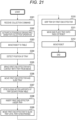
- FIG. 21 is a flowchart illustrating the example of the third operation of the robot system A according to the embodiment.
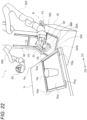
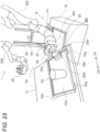
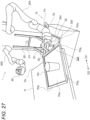
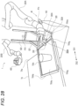
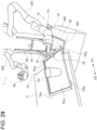
- FIGS. 22 to 29 are perspective views each illustrating an example of a state of the robot 1 included in the third operation.
- the input device 2 receives the collection command for commanding the collection of the tray TRA on the table TA from the user.
- the input device 2 transmits the collection command and the position information on the table TA to the robot 1.
- the table TA is an example of a support plate.
- control device 600 performs the same process as those in steps S202 to S204 of the second operation to move the robot 1 to the table TA and detect a position of the tray TRA as illustrated in FIG. 22 . Further, the control device 600 determines a destination position on the edge TRAa of the tray TRA to be gripped by the first end effector 300A.
- step S305 the control device 600 causes the robot arm 200A to move the first end effector 300A such that the first end effector 300A moves above the placement surface TRAe of the tray TRA over the edge TRAa of the tray TRA.
- the placement surface TRAe is an example of an upper surface of the tray TRA.
- the control device 600 causes the robot arm 200A to lower the first end effector 300A such that the tip end portion 322dd of the second clamping portion 322d of the first end effector 300A is brought into contact with the placement surface TRAe from above and presses the placement surface TRAe downward. Since the tip end portion 322dd protrudes, a force is easily transmitted from the second clamping portion 322d to the tray TRA.
- the bent portion 322dc of the second clamping portion 322d is positioned in the vicinity of the edge TRAa above the placement surface TRAe.
- step S306 the control device 600 causes the robot arm 200A to move the first end effector 300A in a direction DS1 that is a lateral direction from the edge TRAb toward the edge TRAa.
- the robot arm 200A moves the first end effector 300A in a direction along the placement surface TRAe while pressing the tip end portion 322dd of the second clamping portion 322d against the placement surface TRAe.
- the robot arm 200A can slide the tray TRA in the direction DS1 by a friction force between the tip end portion 322dd and the placement surface TRAe.
- the tip end portion 322dd slides on the placement surface TRAe in the direction DS1, and the second clamping portion 322d or the bent portion 322dc thereof abuts or engages with the edge TRAa of the tray TRA.
- the robot arm 200A can also slide the tray TRA in the direction DS1 by the abutment or the engagement. When the abutment or the engagement occurs, the tip end portion 322dd of the second clamping portion 322d may not be pressed against the placement surface TRAe, and may not be in contact with the placement surface TRAe.
- step S307 since the tray TRA slides, the two supports TRAg in the vicinity of the edge TRAa of the tray TRA deviate from the table TA. Accordingly, the edge TRAa and the two supports TRAg protrude in the direction DS1 from the edge TAa of the table TA, and the tray TRA is inclined such that the edge TRAa is positioned below the edge TRAb. As a result, the contact between the tip end portion 322dd of the second clamping portion 322d and the placement surface TRAe and the abutment and engagement between the second clamping portion 322d and the edge TRAa are released, and the sliding of the tray TRA is stopped. After the contact or the engagement is released, the control device 600 ends the operation of the robot arm 200A for sliding the tray TRA and proceeds to the next operation.
- the control device 600 may detect the release of the contact or the engagement by using the result of the process on the image data acquired by the imaging device 40, the loads of the joint driving devices of the robot arm 200A, a detection result of a force sensor arranged at a connection portion between the first end effector 300A and the robot arm 200A, or two or more thereof.
- step S308 the control device 600 causes the robot arm 200A to move the first end effector 300A such that the edge TRAa of the tray TRA is inserted into the recess 322a of the first holding portion 320 by inserting the second clamping portion 322d of the first end effector 300A under the tray TRA and moving the second clamping portion 322d in a direction DS2.
- the direction DS2 is a direction opposite to the direction DS1.
- step S309 the control device 600 causes the robot arm 200A to move the first end effector 300A in the direction DS2 such that the edge TRAa of the tray TRA in the recess 322a is pushed in the direction DS2 by the first holding portion 320.
- the robot arm 200A slides the tray TRA in the direction DS2 via the first holding portion 320.
- the supports TRAg in the vicinity of the edge TRAa abut the edge TAa of the table TA and restrain the sliding of the tray TR. Accordingly, the edge TRAa is deeply inserted into the recess 322a and is deeply engaged therewith.
- the control device 600 may detect the abutment of the supports TRAg by using the result of the process on the image data acquired by the imaging device 40, the loads of the joint driving devices of the robot arm 200A, the detection result of the force sensor arranged at the connection portion between the first end effector 300A and the robot arm 200A, or two or more thereof.
- step S310 as illustrated in FIG. 28 , the control device 600 operates the second holding portion 330 of the first end effector 300A, and causes the second clamping portion 322d and the second holding portion 330 to grip the tray TRA.
- step S311 the control device 600 causes the robot arm 200A to move the first end effector 300A such that the tray TR rises and moves to be placed on the shelf 521 of the rack 520.
- step S312 the control device 600 operates the moving device 100 so as to move the robot 1 to a predetermined standby position, a return place of the tray TRA, or a place specified via the input device 2.
- the robot 1 is used as a robot for providing a service to a person, and may be used for other applications.
- the robot 1 may be used for a work in a factory, a warehouse, and the like.
- the support 500 may have a structure capable of moving the robot arms 200A and 200B up and down in the upper and lower directions D1A and D1B.
- the support 500 may have a stretchable structure such as a nested structure.
- the support column 510 may have a structure capable of moving the display 61 up and down in the upper and lower directions D1A and D1B.
- the support column 510 may have a stretchable structure such as a nested structure, and may have a structure in which the support column 510 itself moves in the upper and lower directions D1A and D1B.
- a drive source for the support 500 and the support column 510 may be an electric actuator such as a servo motor, and may be an actuator that is operated by other power sources such as a gas pressure and a hydraulic pressure.
- the robot arms 200A and 200B are arranged in one moving device 100, but the present disclosure is not limited thereto.
- the robot arms 200A and 200B may be arranged in an object that is not movable.
- the robot arms 200A and 200B may be arranged in different objects.
- the robot 1 includes the two robot arms 200A and 200B, but the present disclosure is not limited thereto.
- the number of robot arms 200 provided in the robot 1 may be one, and may be three or more.
- the robot 1 provided with only the robot arm 200A including the first end effector 300 or 300A can perform the first operation, the second operation, and the third operation.
- the robot 1 can perform the third operation as described above.
- the robot 1 can perform the first operation and the second operation by using the tray TRA used in the third operation.
- the robot arm 200B holds the tray TR so as not to move by using the second end effector 400
- the robot 1 may perform the first operation and the second operation by using the engagement of the supports TRAg of the tray TRA, the abutment of the tray TRA, and the like.
- a control method of a robot includes: causing a first robot arm provided in the robot and a second robot arm provided in the robot to move a first end effector of the first robot arm and a second end effector of the second robot arm such that the first end effector and the second end effector are arranged on both sides of a placed plate-shaped object; causing the first robot arm to move the first end effector toward a first end portion of the plate-shaped object, and causing the first end effector to operate so as to grip the first end portion; and causing the first robot arm to move the first end effector toward a destination position, and causing the first end effector to place the plate-shaped object at the destination position.
- the second end effector when the first end effector moves toward the first end portion of the plate-shaped object, the second end effector restrains the plate-shaped object from sliding. Accordingly, it is possible to reliably position the first end effector to be capable of gripping the plate-shaped object.
- the first end effector positioned in this way holds the plate-shaped object by gripping the plate-shaped object.
- the plate-shaped object is transferred by only the first robot arm. Therefore, it is possible to reliably transfer the plate-shaped object and reduce operations of the two robot arms related to transferring.
- the control method of the robot according to a second aspect of the present disclosure based on the first aspect may include: in a process of placing the plate-shaped object at the destination position, causing the first robot arm to move the first end effector so as to provide, to the plate-shaped object, an inclination at which a second end portion of the plate-shaped object opposite to the first end portion is lower than the first end portion; causing the first robot arm to move the first end effector so as to lower the plate-shaped object in an inclination state and place the second end portion on a surface in the destination position; causing the first end effector to release gripping of the plate-shaped object; and causing the first robot arm to move the first end effector so as to pull out a part of the first end effector from between the plate-shaped object and the surface in the destination position.
- the part of the first end effector is pulled out under the plate-shaped object, and the plate-shaped object is placed.
- the plate-shaped object can be gently placed.
- the second robot arm at the time of pulling out the part of the first end effector, may be caused to move the second end effector so as to press the second end portion of the plate-shaped object toward the surface in the destination position by the second end effector.
- the plate-shaped object is prevented from sliding together with the first end effector at the time of pulling out the part of the first end effector. Therefore, it is possible to reliably arrange the plate-shaped object to the destination position.
- the second robot arm at the time of moving the first end effector toward the first end portion, may be caused to move the second end effector so as to move the second end effector to approach a second end portion of the plate-shaped object opposite to the first end portion.
- the plate-shaped object is prevented from being pushed and moved by the first end effector at the time of moving the first end effector toward the first end portion. Therefore, the plate-shaped object can be reliably gripped.
- the second end effector may include a first holding portion and a second holding portion that are operable to grip an item.
- the second end effector and the second robot arm can perform other operations such as placement of the item onto the plate-shaped object and removal thereof.
- a control method of a robot includes: causing a first robot arm provided in the robot to move a first end effector of the first robot arm such that the first end effector is brought into contact with a plate-shaped object placed on a support plate from above; causing the first robot arm to move the first end effector such that the first end effector laterally slides the plate-shaped object; causing the first robot arm to move the first end effector such that a first end portion of the plate-shaped object which protrudes from the support plate due to the sliding is gripped by the first end effector; and causing the first robot arm to move the first end effector to a destination position and causing the first end effector to place the plate-shaped object at the destination position.
- the sixth aspect it is possible to transfer the plate-shaped object by using one first robot arm.
- the first robot arm can transfer the plate-shaped object by sliding and gripping the plate-shaped object using the first end effector. Since the first end portion of the plate-shaped object after the sliding protrudes from the support plate, the first end effector can easily and reliably grip the first end portion. Therefore, it is possible to reliably transfer the plate-shaped object and reduce operations of the robot arm related to transferring.
- the plate-shaped object may include a support that supports the plate-shaped object on the support plate and protrudes from the plate-shaped object
- the control method may include, in a process of sliding the plate-shaped object, ending an operation of the first robot arm for sliding the plate-like plate-shaped object when the support deviates from the support plate.
- the seventh aspect when the support deviates from the support plate, the inclination of the plate-shaped object changes. Accordingly, the contact between the first end effector and the plate-shaped object can be released. An operation of the robot arm for releasing the contact between the first end effector and the plate-shaped object is unnecessary.
- the control method of a robot according to an eighth aspect of the present disclosure based on the seventh aspect may include, in a process of causing the first end effector to grip the first end portion of the plate-shaped object, causing the first robot arm to move the first end effector such that the first end effector is brought into contact with the first end portion of the plate-shaped object to slide the plate-shaped object; and causing the first end effector to perform a gripping operation when the support comes into contact with the support plate.
- the support in contact with the support plate restrains the sliding of the plate-shaped object. Accordingly, it is possible to reliably engage the first end effector with the first end portion, and it is possible to reliably grip the first end portion by the first end effector due to the engagement.
- the first robot arm at the time of moving the first end effector toward the first end portion, the first robot arm may be caused to move the first end effector so as to insert a first holding portion, which is immovable with respect to the first end effector, of holding portions provided in the first end effector under the plate-shaped object, and at the time of causing the first end effector to operate so as to grip the first end portion, a second holding portion, which is movable with respect to the first end effector, of the holding portions provided in the first end effector may be operated so as to sandwich the first end portion of the plate-shaped object by the second holding portion and the first holding portion.
- the structure of the first end effector is simplified. Due to the structure of the first end effector that is arranged at the tip end of the first robot arm, as an actuator for driving the holding portions, a strong and large electric actuator is often not suitable for mounting on the first end effector. A high load acts on the holding portion that supports the first end portion of a plate-shaped object from below. Since the immovable first holding portion is used as such a holding portion, it is possible to stably and reliably hold the plate-shaped object without using a strong and large electric actuator.
- the first holding portion may include a plate-shaped portion that is inserted under the plate-shaped object and extends in a first direction, the first direction being a direction away from the first end effector. According to the tenth aspect, the first holding portion is easily inserted under the plate-shaped object.
- the plate-shaped portion may have a dimension larger than that of the second holding portion in a second direction intersecting the first direction. According to the eleventh aspect, the first holding portion can stably support the plate-shaped object from below.
- the first holding portion may include, in a base portion of the plate-shaped portion in a direction opposite to the first direction, a recess that receives an end portion of the plate-shaped object and extends in the second direction intersecting the first direction.
- the end portion of the plate-shaped object abuts a wall surface of the recess and is held by the wall surface. It is possible to reliably grip the plate-shaped object and reduce a load acting on the second holding portion.
- the plate-shaped portion may be bent to narrow the recess toward the base portion of the plate-shaped portion.
- the recess has a shape expanding toward an open end. Therefore, it is easy to insert the end portion of the plate-shaped object into the recess.
- the plate-shaped portion may extend in the first direction from an inner surface of the recess facing the plate-shaped portion.
- the first holding portion can stably support the plate-shaped object from below while facilitating the insertion of the end portion of the plate-shaped object into the recess.
- the plate-shaped object placed on a placement portion of the robot may be placed at the destination position. According to the fifteenth aspect, it is possible to transfer the plate-shaped object placed on the robot to a destination position other than the robot.
- the plate-shaped object placed at a position different from the robot is placed on a placement portion of the robot. According to the sixteenth aspect, it is possible to place, on the robot, the plate-shaped object placed at a position other than the robot.
- a robot according to a seventeenth aspect of the present disclosure includes: a control device configured to execute the control method according to any one of the first aspect to the sixteenth aspect of the present disclosure; the first robot arm; the second robot arm; the first end effector; the second end effector; and a moving device on which the first robot arm and the second robot arm are mounted. According to the seventeenth aspect, the same effects as those of the control method of the robot according to the aspects of the present disclosure can be obtained.
- a robot according to an eighteenth aspect of the present disclosure includes: a control device configured to execute the control method according to any one of the first aspect to the sixteenth aspect of the present disclosure; the first robot arm; the first end effector; and a moving device on which the first robot arm is mounted. According to the eighteenth aspect, the same effects as those of the control method of the robot according to the aspects of the present disclosure can be obtained.
- the control method according to the present disclosure may be implemented by a processor, a processing circuit, a combination of the processing circuit and a circuit, an IC card, a single module, or the like.
- the technique of the present disclosure may be a program for executing the control method according to the present disclosure, and may be a non-transitory computer-readable medium storing the program. It is needless to say that the program can be distributed via a transmission medium such as the Internet.
- the functions of the elements disclosed in the present specification can be implemented by using a circuit or a processing circuit including a general-purpose processor, a dedicated processor, an integrated circuit, an ASIC, a conventional circuit, and/or a combination thereof configured or programmed to implement the disclosed functions.
- the processor includes a transistor and other circuits, and thus is regarded as a processing circuit or a circuit.
- the circuit, the unit, and the means are hardware that executes the listed functions or hardware that is programmed to execute the listed functions.
- the hardware may be the hardware disclosed in the present specification, and may be another known hardware configured or programmed to execute the listed functions.
- the hardware is a processor considered as a kind of circuit
- the circuit, the means, or the unit is a combination of hardware and software, and the software is used for the hardware and/or processor.
- the numbers such as the ordinal number and the quantity used above are all illustrated for specifically describing the technique of the present disclosure, and the present disclosure is not limited to the illustrated numbers.
- the connection relation between the components is illustrated for specifically describing the technique of the present disclosure, and the connection relation implementing the function of the present disclosure is not limited thereto.
Landscapes
- Engineering & Computer Science (AREA)
- Robotics (AREA)
- Mechanical Engineering (AREA)
- Health & Medical Sciences (AREA)
- General Health & Medical Sciences (AREA)
- Orthopedic Medicine & Surgery (AREA)
- Human Computer Interaction (AREA)
- Manipulator (AREA)
Abstract
Description
- The present application is intended to prove the priorities and the profits of
JP2022-035737 JP2022-068518, which have been filed to the Japanese patent office on March 8, 2022 and April 18, 2022 - The present disclosure relates to a method of controlling a robot, and a robot.
- For example,
JP2018-008820A - The robot disclosed in
JP2018-008820A - According to an aspect of the present disclosure, a control method of a robot includes: causing a first robot arm provided in the robot and a second robot arm provided in the robot to move a first end effector of the first robot arm and a second end effector of the second robot arm such that the first end effector and the second end effector are arranged on both sides of a placed plate-shaped object; causing the first robot arm to move the first end effector toward a first end portion of the plate-shaped object, and causing the first end effector to operate so as to grip the first end portion; and causing the first robot arm to move the first end effector toward a destination position, and causing the first end effector to place the plate-shaped object at the destination position.
-
- [
FIG. 1] FIG. 1 is a diagram illustrating an example of a configuration of a robot system according to an embodiment. - [
FIG. 2] FIG. 2 is a side view of a moving device inFIG. 1 . - [
FIG. 3] FIG. 3 is a block diagram illustrating an example of components of the robot system according to the embodiment. - [
FIG. 4] FIG. 4 is a side view illustrating an example of components in one state of a first end effector of the robot inFIG. 1 . - [
FIG. 5] FIG. 5 is a side view illustrating an example of the components in the other state of the first end effector of the robot inFIG. 1 . - [
FIG. 6] FIG. 6 is a side view illustrating an example of components in one state of a second end effector of the robot inFIG. 1 . - [
FIG. 7] FIG. 7 is a side view illustrating an example of the components in the other state of the second end effector of the robot inFIG. 1 . - [
FIG. 8] FIG. 8 is a flowchart illustrating an example of a first operation of the robot system according to the embodiment. - [
FIG. 9] FIG. 9 is a perspective view illustrating an example of a state of the robot in the first operation. - [
FIG. 10] FIG. 10 is a perspective view illustrating an example of the state of the robot included in the first operation. - [
FIG. 11] FIG. 11 is a perspective view illustrating an example of the state of the robot included in the first operation. - [
FIG. 12] FIG. 12 is a perspective view illustrating an example of the state of the robot included in the first operation. - [
FIG. 13] FIG. 13 is a perspective view illustrating an example of the state of the robot included in the first operation. - [
FIG. 14] FIG. 14 is a flowchart illustrating an example of a second operation of the robot system according to the embodiment. - [
FIG. 15] FIG. 15 is a perspective view illustrating an example of a state of the robot included in the second operation. - [
FIG. 16] FIG. 16 is a perspective view illustrating an example of the state of the robot included in the second operation. - [
FIG. 17] FIG. 17 is a perspective view illustrating an example of the state of the robot included in the second operation. - [
FIG. 18] FIG. 18 is a perspective view illustrating an example of the state of the robot included in the second operation. - [
FIG. 19] FIG. 19 is a side view illustrating an example of components of another first end effector as inFIG. 4 . - [
FIG. 20] FIG. 20 is a perspective view illustrating an example of components of another tray. - [
FIG. 21] FIG. 21 is a flowchart illustrating an example of a third operation of the robot system according to the embodiment. - [
FIG. 22] FIG. 22 is a perspective view illustrating an example of a state of the robot included in the third operation. - [
FIG. 23] FIG. 23 is a perspective view illustrating an example of the state of the robot included in the third operation. - [
FIG. 24] FIG. 24 is a perspective view illustrating an example of the state of the robot included in the third operation. - [
FIG. 25] FIG. 25 is a perspective view illustrating an example of the state of the robot included in the third operation. - [
FIG. 26] FIG. 26 is a perspective view illustrating an example of the state of the robot included in the third operation. - [
FIG. 27] FIG. 27 is a perspective view illustrating an example of the state of the robot included in the third operation. - [
FIG. 28] FIG. 28 is a perspective view illustrating an example of the state of the robot included in the third operation. - [
FIG. 29] FIG. 29 is a perspective view illustrating an example of the state of the robot included in the third operation. - Hereinafter, an exemplary embodiment of the present disclosure will be described with reference to the drawings. The embodiment described below shows a comprehensive or specific example. Among components in the following embodiment, components that are not described in the independent claims indicating the most significant concept will be described as any components. Each drawing in the attached drawings is a schematic drawing and is not necessarily strictly illustrated. In each of the drawings, substantially the same components are denoted by the same reference numerals, and redundant description may be omitted or simplified. In the present specification and claims, the "device" may mean not only one device but also a system including a plurality of devices.
- An example of a configuration of a robot system A according to an exemplary embodiment will be described with reference to
FIG. 1. FIG. 1 is a diagram illustrating the example of the configuration of the robot system A according to the embodiment. The robot system A includes arobot 1 and aninput device 2. - Although not limited to the following, in the present embodiment, the
input device 2 is arranged at a position away from therobot 1. Theinput device 2 receives input of a command, information, data, and the like by a user, and transmits the received command, information, data, and the like to therobot 1. Theinput device 2 receives a command, information, data, and the like from therobot 1. For example, the user who uses theinput device 2 may be a manager of the robot system A, an operator of therobot 1, a service provider via the robot system A, or a service receiver via the robot system A. - The
input device 2 includes acommunication device 2a communicating with therobot 1, and a processing circuit including a processor P and a memory M. The communication between thecommunication device 2a and therobot 1 is a wireless communication, but may also be a wired communication or a combination of wired and wireless communications. Any wired communication or wireless communication may be used. Thecommunication device 2a and therobot 1 may directly or indirectly perform the wireless communication. In the indirect wireless communication, thecommunication device 2a and therobot 1 may be connected to a communication network via a wired communication or a wireless communication, and may communicate with each other via the communication network. Thecommunication device 2a may include a communication circuit. - The communication network is not particularly limited, and may include, for example, a local area network (LAN), a wide area network (WAN), the Internet, or a combination of two or more thereof. The communication network may use near field communication such as Bluetooth (registered trademark) and ZigBee (registered trademark), a network dedicated line, a communication carrier dedicated line, a public switched telephone network (PSTN), a mobile communication network, an Internet network, satellite communication, or a combination of two or more thereof. The mobile communication network may use a fourth-generation mobile communication system, a fifth-generation mobile communication system, and the like. The communication network can include one or a plurality of networks.
- The
input device 2 may include one or more of a computer such as a personal computer, a smart device such as a smartphone and a tablet computer, a personal digital assistant, a game terminal, a known teaching device such as a teach pendant used for a teaching operation to a robot, a known operation device of a robot, other operation devices, other terminal devices, a device using the above, and a device in which the above is improved. Theinput device 2 may be a dedicated device designed for therobot 1, and may be a general-purpose device available in a general market. When theinput device 2 is a general-purpose device, a function of theinput device 2 may be implemented by installing dedicated software. - The
robot 1 performs an operation of providing a service to the user. Therobot 1 can be used in various services such as care, medical, cleaning, security, guidance, rescue, cooking, commodity provision, and physical distribution. Therobot 1 includes a movingdevice 100, one ormore robot arms 200, asupport 500, and acontrol device 600. Therobot 1 includes asecondary battery module 10, apower supply circuit 20, acommunication device 30, animaging device 40, asensor 50, and apresentation device 60. Although not limited to the following, in the present embodiment, a robot arm capable of functioning as an industrial robot arm is used as therobot arm 200. Theimaging device 40 and thepresentation device 60 may function as devices for communicating with the user around therobot 1. -
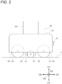
FIG. 2 is a side view of the movingdevice 100 inFIG. 1 . As illustrated inFIG. 2 , the movingdevice 100 is movable by itself, and travels by wheels in the present embodiment. The movingdevice 100 includes amain body 110, drivewheels auxiliary wheels 131 to 134, andmovement driving devices drive wheels auxiliary wheels 131 to 134 are rotatably attached to themain body 110. Thedrive wheels auxiliary wheels 131 to 134 are in contact with a support surface S on which therobot 1 is arranged, and support themain body 110 and therobot 1 from below. - Here, an upper direction D1A, a lower direction D1B, a front direction D2A, a rear direction D2B, a side direction D3A, and a side direction D3B are directions relative to the
robot 1. The upper direction D1A is a direction from the movingdevice 100 toward thesupport 500, and coincides with a vertically upper direction perpendicular to the support surface S when the support surface S is horizontal. The lower direction D1B is a direction opposite to the upper direction D1A, and coincides with a vertically lower direction perpendicular to the support surface S when the support surface S is horizontal. The directions D2A and D2B are directions opposite to each other, and are directions perpendicular to the directions D1A and D1B. The front direction D2A is a forward direction of the movingdevice 100, and the rear direction D2B is a reverse direction of the movingdevice 100. The side directions D3A and D3B are directions opposite to each other, and are directions perpendicular to the directions D1A, D1B, D2A, and D2B. The directions D2A, D2B, D3A, and D3B extend in a horizontal direction when the support surface S is horizontal, and extend along the support surface S when the support surface S is flat. In the present specification and claims, the descriptions "perpendicular", "vertically", "horizontal", and "parallel" may include a completely perpendicular state, a completely vertical state, a completely horizontal state, and a completely parallel state, respectively, and may include a substantially perpendicular state, a substantially vertical state, a substantially horizontal state, and a substantially parallel state close to the completely perpendicular state, the completely vertical state, the completely horizontal state, and the completely parallel state, respectively. - Although not limited to the following, in the present embodiment, the
auxiliary wheels 131 to 134 are arranged around thedrive wheels main body 110. Directions of respective rotation shafts of theauxiliary wheels 131 to 134 may be fixed, and the directions of the respective rotation shafts thereof may be changed like universal casters. Thedrive wheels drive wheels main body 110. - The
movement driving devices main body 110 and rotationally drive thedrive wheels movement driving devices control device 600. Themovement driving devices device 100 to perform forward movement, reverse movement, and various turning by controlling a rotation direction and a rotation speed of thedrive wheels - A structure of the moving
device 100 is not limited to the structure described above, and any structure can be used as long as the movingdevice 100 can be moved in various directions. For example, the movingdevice 100 may move by using other traveling means such as a crawler without using the wheels. - As illustrated in
FIG. 1 , thesupport 500 is arranged on the movingdevice 100 and is supported by the movingdevice 100. Thesupport 500 has a columnar shape extending in the upper direction D1A from the movingdevice 100. Thesupport 500 accommodates and supports various components of therobot 1. Thesupport 500 includes asupport column 510 and arack 520. Thesupport column 510 extends in the upper direction D1A from thesupport 500 and supports thepresentation device 60. Therack 520 is arranged in the front direction D2A of thesupport 500. Therack 520 includes one ormore shelves 521 on which a plate-shaped object can be placed. In the present embodiment, twoshelves 521 are arranged side by side in the upper and lower directions D1A and D1B. Therack 520 is an example of a placement portion. - Although not limited to the following, in the present embodiment, the
robot 1 includes tworobot arms robot arms 200. Therobot arms support 500 and are supported by thesupport 500. Therobot 1 is a double-arm type robot. Each of therobot arms - Although not limited to the following, in the present embodiment, the
robot arm 200A includes abase 201A, six links LA1 to LA6, six joints JA1 to JA6 that interconnect thebase 201A and the links LA1 to LA6, joint driving devices MA1 to MA6 that drive the joints JA1 to JA6, and afirst end effector 300. Therobot arm 200B includes abase 201B, six links LB1 to LB6, six joints JB1 to JB6 that interconnect thebase 201B and the links LB1 to LB6, joint driving devices MB1 to MB6 that drive the joints JB1 to JB6, and asecond end effector 400. The joints JA1 to JA6 and JB1 to JB6 are rotary joints. Each of the joint driving devices MA1 to MA6 and MB1 to MB6 includes a servo motor using electric power as a power source and serving as an electric actuator. The servo motors are controlled by thecontrol device 600. The joint driving devices MA1 to MA6 and MB1 to MB6 are illustrated inFIG. 3 . - The
bases support 500. Thebases support column 510 in the side directions D3A and D3B, respectively. Thebases bases - The links LA2 and LB2 are connected to the links LA1 and LB1 via the joints JA2 and JB2, respectively. The links LA2 and LB2 extend in directions intersecting pivot shafts of the joints JA2 and JB2, and for example, extend in directions perpendicular to the pivot shafts of the joints JA2 and JB2, respectively. The pivot shafts of the joints JA2 and JB2 extend in directions intersecting the pivot shafts of the joints JA1 and JB1, and for example, extend in directions perpendicular to the pivot shafts of the joints JA1 and JB1, respectively.
- The links LA3 and LB3 are connected to the links LA2 and LB2 via the joints JA3 and JB3, respectively. The links LA3 and LB3 extend in directions intersecting pivot shafts of the joints JA3 and JB3, and for example, extend in directions perpendicular to the pivot shafts of the joints JA3 and JB3, respectively. The pivot shafts of the joints JA3 and JB3 extend in directions along the pivot shafts of the joints JA2 and JB2, and for example, extend in directions parallel to the pivot shafts of the joints JA2 and JB2, respectively.
- The links LA4 and LB4 are connected to the links LA3 and LB3 via the joints JA4 and JB4, respectively. The links LA4 and LB4 extend in directions along pivot shafts of the joints JA4 and JB4, respectively. The pivot shafts of the joints JA4 and JB4 extend in directions intersecting the pivot shafts of the joints JA3 and JB3, and for example, extend in directions perpendicular to the pivot shafts of the joints JA3 and JB3, respectively.
- The links LA5 and LB5 are connected to the links LA4 and LB4 via the joints JA5 and JB5, respectively. The links LA5 and LB5 extend in directions intersecting pivot shafts of the joints JA5 and JB5, and for example, extend in directions perpendicular to the pivot shafts of the joints JA5 and JB5, respectively. The pivot shafts of the joints JA5 and JB5 extend in directions intersecting the pivot shafts of the joints JA4 and JB4, and for example, extend in directions perpendicular to the pivot shafts of the joints JA4 and JB4, respectively.
- The links LA6 and LB6 are connected to the links LA5 and LB5 via the joints JA6 and JB6, respectively. The links LA6 and LB6 extend in directions along pivot shafts of the joints JA6 and JB6, respectively. The pivot shafts of the joints JA6 and JB6 extend in directions intersecting the pivot shafts of the joints JA5 and JB5, and for example, extend in directions perpendicular to the pivot shafts of the joints JA5 and JB5, respectively. Each of the links LA6 and LB6 includes a mechanical interface at a tip end thereof, and is physically and electrically connected to the
end effector - The
end effectors end effectors robot 1. Theend effectors end effectors FIG. 3 . For example, a force sensor for detecting a direction and a magnitude of an acting force may be arranged at each of connection portions between theend effectors end effectors - The
robot arms robot arms robot arms 200 may be one or more, and preferably two or more. The number of joints of eachrobot arm 200 may be two or more. The joints of therobot arm 200 are not limited to the rotary joints, and may include, for example, a prismatic joint. - The
presentation device 60 presents various information to the user around therobot 1. Although not limited to the following, in the present embodiment, thepresentation device 60 includes adisplay 61 attached to thesupport column 510. Thedisplay 61 displays an image of image data transmitted from thecontrol device 600. Thecontrol device 600 may cause thedisplay 61 to display an image for communicating with the user facing therobot 1, an image in response to a command received from theinput device 2, an image for providing various other information to the user, and the like. Thepresentation device 60 may include a speaker that converts an audio signal into a sound wave and emits the sound wave as audio, a projector that projects an image, and the like. The speaker and the projector may output an audio and an image corresponding to an audio signal and an image signal transmitted from thecontrol device 600, respectively. - The
imaging device 40 includesimaging devices 41a to 41f, and detects various information around therobot 1. Each of theimaging devices 41a to 41f includes a camera that captures a digital image. One or more of theimaging devices 41a to 41f may include a three-dimensional camera capable of detecting a distance to a subject. Examples of the three-dimensional camera may include a stereo camera, a time-of-flight-camera (TOF camera), a pattern light projection camera such as fringe projection, and a camera using a light-section method. Each of theimaging devices 41a to 41f outputs data of the captured image to thecontrol device 600. Thecontrol device 600 may use the image data acquired by theimaging devices 41a to 41f in a control performed by thecontrol device 600 itself, and may output the image data to theinput device 2. Thecontrol device 600 may perform an image process for extracting the subject from the image, detecting the distance from the camera to the subject, and the like. - The
imaging devices robot arms end effectors imaging device 41c is arranged at thedisplay 61, and captures an image of the user facing therobot 1. Theimaging device 41d is arranged at thesupport 500, and captures an image of the front of therobot 1. Theimaging device 41e is arranged at the movingdevice 100, and captures an image of the support surface S in front of therobot 1 and the vicinity thereof. Theimaging device 41f is arranged at thesupport 500, and captures an image of the rear of therobot 1. Therobot 1 may include a microphone that acquires an audio from the surroundings thereof and outputs an audio signal of the audio. The microphone may output the audio signal to thecontrol device 600. - The
sensor 50 detects various information around therobot 1. Thesensor 50 scans the periphery of therobot 1, and outputs a scan result to thecontrol device 600. Thecontrol device 600 may use the scan result of thesensor 50 in the control performed by thecontrol device 600 itself, and may output the scan result to theinput device 2. Although not limited to the following, in the present embodiment, thesensor 50 is arranged in the movingdevice 100, and is oriented toward the front direction D2A. Thesensor 50 may scan a horizontal range of spreading from the movingdevice 100 toward the front direction D2A and the side directions D3A and D3B. Thesensor 50 may scan a vertical range including the support surface S and the vicinity thereof. Thesensor 50 may be capable of detecting the support surface S and an object such as an article within the scanned ranges, and a distance to the object. Such asensor 50 can detect a state of the support surface S in front of therobot 1 and the article on the support surface S as well as positions of various portions on the support surface S and a position of the article. - The
sensor 50 performs detection using a light wave, a laser, magnetism, a radio wave, an electromagnetic wave, an ultrasonic wave or a combination of two or more thereof, and may include a photoelectric sensor, a laser sensor, a radio wave sensor, an electromagnetic wave sensor, an ultrasonic sensor, various lidars (LiDAR) or a combination of two or more thereof. - The
control device 600, thesecondary battery module 10, thepower supply circuit 20, and thecommunication device 30 are arranged in thesupport 500. Thesecondary battery module 10 functions as an electric power source of therobot 1. Thesecondary battery module 10 includes one or more secondary batteries. The secondary battery is a battery capable of charging and discharging electric power. Examples of the secondary battery may include a lead storage battery, a lithium ion secondary battery, an all-solid-state battery, a nickel-hydrogen storage battery, and a nickel-cadmium storage battery. - The
power supply circuit 20 controls supply and demand of the electric power to thesecondary battery module 10 in response to a command and the like from thecontrol device 600. For example, thepower supply circuit 20 may include devices such as a converter, an inverter, a transformer, and an amplifier. Thepower supply circuit 20 receives electric power supplied from an external power supply EP such as a commercial power supply, and supplies the electric power to thesecondary battery module 10 and stores the electric power while controlling the electric power. Thepower supply circuit 20 supplies the electric power stored in thesecondary battery module 10 to components consuming electric power in therobot 1 while controlling the electric power. The external power supply EP is illustrated inFIG. 3 . - The
communication device 30 communicates with thecommunication device 2a of theinput device 2. Thecommunication device 30 has a structure suitable for communication to be used. Thecommunication device 30 may include a communication circuit. - The
control device 600 controls theentire robot 1.FIG. 3 is a block diagram illustrating an example of components of the robot system A according to the embodiment. As illustrated inFIG. 3 , thecontrol device 600 is communicably connected to theinput device 2 via thecommunication device 30. Thecontrol device 600 controls operations of various components of therobot 1 in response to a command and the like received from theinput device 2. Thecontrol device 600 controls operations of various components of therobot 1 according to a stored control program. - Examples of the components as control targets by the
control device 600 may include themovement driving devices end effectors power supply circuit 20, thecommunication device 30, theimaging devices 41a to 41f, thesensor 50, thedisplay 61, and the like, but not all of the above are required. - When controlling the electric power supplied to the components, the
control device 600 may output a command value of a current and the like to thepower supply circuit 20 and supply the electric power of thepower supply circuit 20 and thesecondary battery module 10 to the components. Thecontrol device 600 may servo-control the servo motors. Thecontrol device 600 may acquire, from each servo motor, a detection result of a rotation sensor such as an encoder provided in the servo motor. Thecontrol device 600 may acquire a value of a supplied current to the servo motor from a current sensor that may be arranged at the servo motor, or from thepower supply circuit 20. Thecontrol device 600 may determine a command value of a current to the servo motor by using the detection result of the rotation sensor and the value of the supplied current as feedback information. - The
control device 600 may cause the components of therobot 1 to perform one or more of an operation in manual driving, an operation in autonomous driving, and an operation in a combination of the manual driving and the autonomous driving. - In the manual driving, the
control device 600 may perform a control to operate the components of therobot 1 in accordance with an operation content input to theinput device 2 in a sequential manner. Thecontrol device 600 may perform the control in accordance with a manual driving program. - In the autonomous driving, the
control device 600 may perform a control such that the components of therobot 1 automatically, that is, autonomously operate a series of tasks corresponding to a command input to theinput device 2. Thecontrol device 600 may perform the control according to an autonomous driving program corresponding to the tasks. - In the combination of the manual driving and the autonomous driving, the
control device 600 may perform a control such that the components of therobot 1 appropriately execute the operation according to the operation content in a sequential manner and the operation of autonomously executing the series of tasks in response to the operation content and the command received from theinput device 2. Thecontrol device 600 may perform the control according to a hybrid driving program obtained by combining the autonomous driving program and the manual driving program, and may perform the control according to the autonomous driving program and the manual driving program in a sequential manner. - Similarly to the
input device 2, thecontrol device 600 includes the processing circuit including the processor P and the memory M. For example, thecontrol device 600 may be an electronic circuit board, an electronic control unit, a microcomputer, or other electronic devices. The processor P transmits and receives a command, information, data, and the like to and from other devices. The processor P inputs a signal from various devices and outputs a control signal to a control target. - For example, the memory M may include a volatile semi-conductor memory such as a random access memory (RAM), a nonvolatile semi-conductor memory such as a read-only memory (ROM), a hard disk, a solid state drive (SSD), or a combination of two or more thereof. The memory M stores a program to be executed by the processor P, various types of data, and the like.
- At least a part of a plurality of functions of the
control device 600 and theinput device 2 may be implemented by cooperation of the processor P and the memory M. The processor P and the memory M including the RAM and the ROM form a computer system. For example, the computer system may implement the above functions by the processor P executing a program recorded in the ROM using the RAM as a work area. - A part or all of the functions of the
control device 600 and theinput device 2 may be implemented by the computer system, may be implemented by a dedicated hardware circuit such as an electronic circuit or an integrated circuit, and may be implemented by a combination of the computer system and the hardware circuit. For example, each of thecontrol device 600 and theinput device 2 may execute a process by centralized control by a single computer, and may execute a process by distributed control by cooperation of a plurality of computers. - Without being limited to the following, the processor P may include, for example, one or more of a central processing unit (CPU), a micro processing unit (MPU), a graphics processing unit (GPU), a microprocessor, a processor core, a multiprocessor, an application-specific integrated circuit (ASIC), a field programmable gate array (FPGA), and a reconfigurable processor. The processor P may implement a process by a logic circuit or a dedicated circuit which is a hardware circuit formed in, for example, an integrated circuit such as an integrated circuit (IC) chip and a large scale integration (LSI). The functions of the
control device 600 and theinput device 2 may be implemented by an integrated circuit that is individually integrated into one chip, and may be implemented by an integrated circuit that is integrated into one chip so as to include a part or all of the functions. -
FIGS. 4 and 5 are side views illustrating examples of components in two different states of thefirst end effector 300 of therobot 1 inFIG. 1 .FIGS. 4 and 5 show the inside of amain body 310 of thefirst end effector 300. As illustrated inFIG. 4 , thefirst end effector 300 has a structure suitable for holding a plate-shaped object PL. Thefirst end effector 300 includes themain body 310, afirst holding portion 320, asecond holding portion 330, the driving device ME1, adrive shaft 340, and a drivenshaft 350. Themain body 310 includes a mechanical interface connected to the mechanical interface of the link LA6 or LB6 of therobot arm - The driving device ME1, the
drive shaft 340, and the drivenshaft 350 are arranged in themain body 310. Thedrive shaft 340 is connected to the driving device ME1 so as to be rotationally driven by the driving device ME1. The drivenshaft 350 is engaged with thedrive shaft 340 by gears. A drivengear 351 rotating integrally with the drivenshaft 350 is engaged with adrive gear 341 rotating integrally with thedrive shaft 340. The driving device ME1 rotationally drives the drivenshaft 350 via thedrive shaft 340. - The
first holding portion 320 is fixed to themain body 310 in an immovable manner. At least a part of thefirst holding portion 320 may be integrated with themain body 310. Thefirst holding portion 320 includes abase link 321 extending from themain body 310 in a direction D4A, and atip end link 322 connected to a tip end of thebase link 321. Thebase link 321 and thetip end link 322 may be integrated. Thebase link 321 may have a columnar or finger-like shape and function as a finger portion of the robot hand. - Here, directions D4A, D4B, D5A, D5B, D6A, and D6B illustrated in
FIGS. 4 and 5 are directions relative to thefirst end effector 300. The direction D4A is a direction away from themain body 310, and the direction D4B is a direction opposite to the direction D4A. The directions D5A and D5B are directions opposite to each other, and are directions perpendicular to the directions D4A and D4B. The directions D6A and D6B are directions opposite to each other, and are directions that are perpendicular to the directions D4A and D4B and intersect the directions D5A and D5B. Although not limited to the following, in the present embodiment, the directions D6A and D6B are directions perpendicular to the directions D5A and D5B. - The
tip end link 322 includes arecess 322a, and therecess 322a opens in the direction D4A and opens in the directions D5A and D5B. Thetip end link 322 includes abase portion 322b connected to thebase link 321, and clampingportions recess 322a is formed between the clampingportions first clamping portion 322c extends from thebase portion 322b in the direction D4A and the directions D5A and D5B. Thefirst clamping portion 322c has a flat surface 322ca facing thesecond clamping portion 322d and oriented in the direction D6A. The widths of thefirst clamping portion 322c and the surface 322ca in the directions D5A and D5B are larger than the width of thebase portion 322b. For example, thefirst clamping portion 322c may have a plate shape. - The
second clamping portion 322d is arranged in the direction D6A with respect to thefirst clamping portion 322c. Thesecond clamping portion 322d extends from thebase portion 322b in the direction D4A and the directions D5A and D5B. Thesecond clamping portion 322d protrudes toward the direction D4A with respect to thefirst clamping portion 322c. Thesecond clamping portion 322d has flat surfaces 322da and 322db facing thefirst clamping portion 322c. The widths of thesecond clamping portion 322d and the surfaces 322da and 322db in the directions D5A and D5B may be larger than the width of thebase portion 322b, and may be, for example, equal to the widths of thefirst clamping portion 322c and the surface 322ca in the directions D5A and D5B. - The surface 322da is positioned in the direction D4A with respect to the surface 322db, and is oriented in the direction D6B. The surface 322da may be extend along the surface 322ca, and may be, for example, parallel to the surface 322ca. The surface 322db is inclined to approach the surface 322ca as advancing in the direction D4B. Accordingly, the
recess 322a includes a shape that tapers toward the direction D6B as advancing in the direction D4B. For example, therecess 322a has a triangular prism shape having a wedge-shaped cross section. Although not limited to the following, in the present embodiment, end portions of the surfaces 322db and 322ca in the direction D4A are positioned at the same distance from thebase portion 322b, and face each other in the directions D6A and D6B. - The
second clamping portion 322d has a plate shape bent at a bent portion 322dc as a boundary between the surfaces 322da and 322db. Accordingly, it is easy to insert thesecond clamping portion 322d into a gap between a surface on which the plate-shaped object PL is placed and the plate-shaped object PL. Further, even when an attitude of theend effector 300 with respect to the plate-shaped object PL is different from the attitude inFIG. 4 and the surface 322da has an angle so as not to be parallel to a surface of the plate-shaped object PL, it is easily to insert the plate-shaped object PL into therecess 322a. At least a part of thesecond clamping portion 322d may include a tapered shape such that the thickness thereof in the direction D6A decreases as advancing in the direction D4A. The plate-shaped object PL inserted into therecess 322a is in contact with the surface 322ca and one or both of the surfaces 322da and 322db, and is clamped by the clampingportions first holding portion 320. - The
second holding portion 330 is attached to themain body 310 in an operable manner. Thesecond holding portion 330 is arranged in the direction D6B with respect to thefirst holding portion 320. Thesecond holding portion 330 faces thefirst holding portion 320 in the direction D6A. Thesecond holding portion 330 includes alink mechanism 331 connected to anend portion 310a of themain body 310 in the direction D4A, and atip end link 332 connected to a tip end of thelink mechanism 331. For example, theend portion 310a may be positioned on a side opposite to the mechanical interface of themain body 310. - The
link mechanism 331 includeslinks 331a to 331e. Thelinks main body 310 at respective proximal ends thereof, and extend along each other. A tip end of thelink 331a is pivotally connected to an intermediate position of thelink 331c. A tip end of thelink 331b is pivotally connected to a proximal end of thelink 331d. Thelinks tip end link 332 at respective tip ends thereof, and extend along each other. A proximal end of thelink 331c is pivotally connected to a pivotingmember 352 that pivots integrally with the drivenshaft 350. InFIG. 4 , a connection portion between thelink 331c and the pivotingmember 352 is positioned in the direction D6A with respect to connection portions between thelinks main body 310. A connection portion between the tip end of thelink 331a and thelink 331c is pivotally connected to one end of thelink 331e. A connection portion between the tip end of thelink 331b and the proximal end of thelink 331d is pivotally connected to the other end of thelink 331e. Thelink mechanism 331 has a structure including two parallel links connected to each other. - The
tip end link 332 extends toward the direction D6A as advancing in the direction D4A. Thetip end link 332 extends toward thefirst holding portion 320. Thetip end link 332 has a shape that tapers toward a tip end, and has, for example, a wedge-shaped or claw-shaped cross-sectional shape. The width of thetip end link 332 in the directions D5A and D5B is smaller than the widths of the clampingportions tip end link 332 can come into contact with the article is smaller than a contact area in which the clampingportions - In the
first end effector 300 in the state illustrated inFIG. 4 , when the driving device ME1 rotationally drives the drivenshaft 350 toward a direction R1 via thedrive shaft 340, thefirst end effector 300 is in the state illustrated inFIG. 5 . When the pivotingmember 352 pivots toward the direction R1 to move the proximal end of thelink 331c, thelink mechanism 331 moves thetip end link 332 in parallel in the directions D4B and D6A. Accordingly, the tip end of the tip end link 332 approaches thesecond clamping portion 322d. Thesecond holding portion 330 moves thetip end link 332 to approach or separate away from thesecond clamping portion 322d. Thesecond holding portion 330 presses the plate-shaped object PL inserted into therecess 322a against thesecond clamping portion 322d by using thetip end link 332, thereby strengthening the holding of the plate-shaped object PL. That is, thefirst holding portion 320 and thesecond holding portion 330 grip the plate-shaped object PL. -
FIGS. 6 and 7 are side views illustrating examples of components in two different states of thesecond end effector 400 of therobot 1 inFIG. 1 .FIGS. 6 and 7 show the inside of amain body 410 of thesecond end effector 400. As illustrated inFIG. 6 , thesecond end effector 400 includes themain body 410, afirst holding portion 420, asecond holding portion 430, the driving device ME2, adrive shaft 440, a first drivenshaft 450, and a second drivenshaft 460. Themain body 410 includes a mechanical interface connected to the mechanical interface of the link LA6 or LB6 of therobot arm - The driving device ME2, the
drive shaft 440, and the drivenshafts main body 410. Thedrive shaft 440 is connected to the driving device ME2 so as to be rotationally driven by the driving device ME2. The first drivenshaft 450 is engaged with thedrive shaft 440 by gears, and the second drivenshaft 460 is engaged with the first drivenshaft 450 by gears. A drivengear 451 rotating integrally with the first drivenshaft 450 is engaged with adrive gear 441 rotating integrally with thedrive shaft 440. A drivengear 461 rotating integrally with the second drivenshaft 460 is engaged with the drivengear 451. The driving device ME2 rotationally drives the drivenshafts drive shaft 440. - Here, directions D7A, D7B, D8A, D8B, D9A, and D9B illustrated in
FIGS. 6 and 7 are directions relative to thesecond end effector 400, and are defined similarly to the directions D4A, D4B, D5A, D5B, D6A, and D6B of thefirst end effector 300. The directions D7A and D7B respectively correspond to the directions D4A and D4B, the directions D8A and D8B respectively correspond to the directions D5A and D5B, and the directions D9A and D9B respectively correspond to the directions D6A and D6B. - The holding
portions end portion 410a of themain body 410 in the direction D7A in an operable manner. Thesecond holding portion 430 is arranged in the direction D9A with respect to thefirst holding portion 420. Thesecond holding portion 430 faces thefirst holding portion 420 in the direction D9B. For example, theend portion 410a may be positioned on a side opposite to the mechanical interface of themain body 410. - The holding
portions link mechanisms end portion 410a, and tipend links link mechanisms link mechanisms link mechanism 331 of thefirst end effector 300. Although not limited to the following, in the present embodiment, thelink mechanisms link 421a of thelink mechanism 421 is pivotally connected to a pivotingmember 452 that pivots integrally with the first drivenshaft 450. Alink 431a of thelink mechanism 431 is pivotally connected to a pivotingmember 462 that pivots integrally with the second drivenshaft 460. - The
tip end links connection portions link mechanisms end portions tip end portions connection portions tip end portions tip end portions tip end portions connection portions - When receiving a force in the direction D7B in a state of sliding toward the direction D7A with respect to the
connection portion 422a, thetip end portion 422b may move toward the direction D9B while moving toward the direction D7B. When receiving a force in the direction D9B in the above state, thetip end portion 422b may move toward the direction D7B while moving toward the direction D9B. When receiving a force in the direction D7B in a state of sliding toward the direction D7A with respect to theconnection portion 432a, thetip end portion 432b may move toward the direction D9A while moving toward the direction D7B. When receiving a force in the direction D9A in the above state, thetip end portion 422b may move toward the direction D7B while moving toward the direction D9A. In the present embodiment, thetip end portions connection portions connection portions tip end portions connection portions - Biasing members such as coil springs may be arranged in the
connection portions tip end portions connection portion 422a absorbs an impact received by the holdingportion 420 when thetip end portion 422b receives a force in the direction D7B or D9B from an object W. The biasing member of theconnection portion 432a absorbs an impact received by the holdingportion 430 when thetip end portion 432b receives a force in the direction D7B or D9A from the object W. The biasing members enable the holdingportions tip end links - In the
second end effector 400 in the state illustrated inFIG. 6 , when the driving device ME2 rotationally drives the first drivenshaft 450 in the direction R1 via thedrive shaft 440, the first drivenshaft 450 rotationally drives the second drivenshaft 460 in a direction R2 opposite to the direction R1. Thesecond end effector 400 is in the state illustrated inFIG. 7 . When the pivotingmember 452 pivots toward the direction R1, thelink mechanism 421 moves thetip end link 422 in parallel in the directions D7B and D9A. When the pivotingmember 462 pivots toward the direction R2, thelink mechanism 431 moves thetip end link 432 in parallel in the directions D7B and D9B. Accordingly, thesecond end effector 400 can sandwich and grip the object W by thetip end links - An example of a first operation of the robot system A according to the embodiment will be described with reference to
FIG. 8. FIG. 8 is a flowchart illustrating the example of the first operation of the robot system A according to the embodiment.FIGS. 9 to 13 are perspective views each illustrating an example of a state of therobot 1 included in the first operation. In the first operation, therobot 1 uses therobot arms - In step S101, the
input device 2 receives a food service command for commanding the food service by the tray TR to the user using a table TA. Theinput device 2 transmits the food service command and position information on the table TA to therobot 1. At this time, the tray TR on which a vessel containing a beverage as an example of food is placed is arranged on theshelves 521 of therack 520 of therobot 1 by a service provider. - In step S102, the
control device 600 activates an autonomous driving program for a food service operation of therobot 1, and executes a subsequent control of therobot 1 according to the autonomous driving program. The autonomous driving program for the food service operation is a program for causing therobot 1 to autonomously transfer the tray TR from a starting point to a destination point and provide the food service by the tray TR at the destination point. - In step S103, the
control device 600 moves therobot 1 to the table TA while operating the movingdevice 100 and causing theimaging device 40 to capture an image. Thecontrol device 600 moves therobot 1 while avoiding an obstacle by using map information stored in the memory M, a result of the image process on image data acquired by theimaging device 40, and the like. - In step S104, when the
robot 1 arrives at the front of the table TA, thecontrol device 600 causes theimaging device 40 to capture images of the table TA and the tray TR. Thecontrol device 600 performs the image process on the image data acquired by theimaging device 40 so as to detect a position, a shape, and a size of the tray TR on therack 520 and a position, a shape, and a size of the table TA. Further, thecontrol device 600 determines a destination position on an edge TRa of the tray TR to be gripped by thefirst end effector 300 and a destination position on the table TA in which the tray TR is to be arranged. In the subsequent control, thecontrol device 600 causes therobot 1 to operate while causing theimaging device 40 to capture an image. Further, thecontrol device 600 adjusts positions and attitudes of thefirst end effector 300, thesecond end effector 400, and the tray TR by using a result of the process on the image data acquired by theimaging device 40 and the like. - In step S105, as illustrated in
FIG. 9 , thecontrol device 600 causes therobot arm 200A to move thefirst end effector 300 such that thesecond clamping portion 322d of thefirst end effector 300 is positioned on a lateral side of and in the vicinity of the destination position on the edge TRa of the tray TR. Thecontrol device 600 causes therobot arm 200B to move thesecond end effector 400 such that thetip end portions second end effector 400 are positioned on a lateral side of and in the vicinity of an edge TRb of the tray TR opposite to the edge TRa. For example, thesecond clamping portion 322d and thetip end portions end effectors - In step S106, as illustrated in
FIG. 10 , thecontrol device 600 causes therobot arm 200A to move thefirst end effector 300 such that thesecond clamping portion 322d of thefirst end effector 300 is inserted under the tray TR. Thecontrol device 600 adjusts the attitude of thefirst end effector 300 such that the surface 322da of thesecond clamping portion 322d is horizontal under the tray TR. Thecontrol device 600 causes therobot arm 200A to move thefirst end effector 300 until the edge TRa of the tray TR is inserted into therecess 322a of thefirst holding portion 320. At this time, thetip end portions second end effector 400 abut the edge TRb of the tray TR to restrain sliding of the tray TR. At the time of inserting thesecond clamping portion 322d under the tray TR, thecontrol device 600 may cause therobot arm 200B to move thesecond end effector 400 such that thetip end portions first end effector 300 is in the state illustrated inFIG. 4 . - The
control device 600 may detect the insertion of the edge TRa into therecess 322a by using the result of the process on the image data acquired by theimaging device 40, loads of the joint driving devices of one or both of therobot arms end effectors robot arms - In step S107, the
control device 600 operates thesecond holding portion 330 of thefirst end effector 300, and causes thesecond clamping portion 322d and thesecond holding portion 330 to grip the tray TR. Accordingly, thefirst end effector 300 is in the state illustrated inFIG. 5 . - In step S108, as illustrated in
FIG. 11 , thecontrol device 600 causes therobot arm 200A to move thefirst end effector 300 such that the tray TR rises and moves to the destination position on the table TA. Thecontrol device 600 causes therobot arm 200B to move thesecond end effector 400 such that thetip end portions control device 600 adjusts a movement path of the tray TR by using the result of the process on the image data acquired by theimaging device 40 and the like. The order of movement of theend effectors - In step S109, as illustrated in
FIG. 12 , thecontrol device 600 causes therobot arm 200A to move thefirst end effector 300 such that the tray TR moves downward while the tray TR is slightly inclined so that the edge TRb is positioned below the edge TRa. When the edge TRb comes into contact with a surface of the table TA, thecontrol device 600 stops the movement of thefirst end effector 300. Thecontrol device 600 may detect the contact between the edge TRb and the table TA by using the result of the process on the image data acquired by theimaging device 40, the loads of the joint driving devices of therobot arm 200A, the detection result of the force sensor arranged at the connection portion between thefirst end effector 300 and therobot arm 200A, or two or more thereof. - In step S110, as illustrated in
FIG. 13 , thecontrol device 600 causes therobot arm 200B to move thesecond end effector 400 such that thetip end portion second end effector 400 comes into contact with an upper surface of the tray TR near the edge TRb and presses the tray TR downward toward the surface of the table TA. Thecontrol device 600 may detect a pressing force of thesecond end effector 400 and adjust the pressing force by using the loads of the joint driving devices of therobot arm 200B, the detection result of the force sensor arranged at the connection portion between thesecond end effector 400 and therobot arm 200B, or a combination thereof. - In step Sill, the
control device 600 causes therobot arm 200A to move thefirst end effector 300 such that thesecond clamping portion 322d of thefirst end effector 300 is pulled out under the tray TR. After pulling out thesecond clamping portion 322d, thecontrol device 600 causes therobot arm 200B to move thesecond end effector 400 such that thetip end portions - In step S112, the
control device 600 operates the movingdevice 100 so as to move therobot 1 to a predetermined standby position or a place specified via theinput device 2. - An example of a second operation of the robot system A according to the embodiment will be described with reference to
FIG. 14. FIG. 14 is a flowchart illustrating the example of the second operation of the robot system A according to the embodiment.FIGS. 15 to 18 are perspective views each illustrating an example of a state of therobot 1 included in the second operation. In the second operation, therobot 1 uses therobot arms - In step S201, the
input device 2 receives a collection command for commanding the collection of the tray TR on the table TA from the user. Theinput device 2 transmits the collection command and the position information on the table TA to therobot 1. - In step S202, the
control device 600 activates an autonomous driving program for a collection operation of therobot 1, and executes a subsequent control of therobot 1 in accordance with the autonomous driving program. The autonomous driving program for the collection operation is a program for causing therobot 1 to autonomously move from a starting point to a destination point, collect the tray TR at the destination point, and discard an item on the tray TR. - In step S203, the
control device 600 moves therobot 1 to the table TA while operating the movingdevice 100 and causing theimaging device 40 to capture an image as in step S103 of the first operation. - In step S204, when the
robot 1 arrives at the front of the table TA, thecontrol device 600 causes theimaging device 40 to capture images of the table TA, the tray TR, and a waste box WB. Thecontrol device 600 performs the image process on the image data acquired by theimaging device 40 so as to detect a position, a shape, and a size of the table TA, a position, a shape, and a size of the tray TR on the table TA, and a position, a shape, and a size of the waste box WB. Further, thecontrol device 600 determines a destination position on the edge TRa of the tray TR to be gripped by thefirst end effector 300. In the subsequent control, thecontrol device 600 causes therobot 1 to operate while causing theimaging device 40 to capture an image. Further, thecontrol device 600 adjusts positions and attitudes of thefirst end effector 300, thesecond end effector 400, and the tray TR by using a result of the process on the image data acquired by theimaging device 40 and the like. - In step S205, as illustrated in
FIG. 15 , thecontrol device 600 causes therobot arm 200A to move thefirst end effector 300 such that thesecond clamping portion 322d of thefirst end effector 300 is positioned on a lateral side of and in the vicinity of the destination position on the edge TRa of the tray TR. Thecontrol device 600 causes therobot arm 200B to move thesecond end effector 400 such that thetip end portions second end effector 400 are positioned on a lateral side of and in the vicinity of the edge TRb of the tray TR. For example, thesecond clamping portion 322d and thetip end portions end effectors - In step S206, as illustrated in
FIG. 16 , thecontrol device 600 causes therobot arm 200A to move thefirst end effector 300 such that thesecond clamping portion 322d of thefirst end effector 300 is inserted between the tray TR and the surface of the table TA. Thecontrol device 600 causes therobot arm 200A to move thefirst end effector 300 until the edge TRa of the tray TR is inserted into therecess 322a of thefirst holding portion 320. At this time, thetip end portions second end effector 400 abut the edge TRb of the tray TR to restrain sliding of the tray TR. At the time of inserting thesecond clamping portion 322d under the tray TR, thecontrol device 600 may cause therobot arm 200B to move thesecond end effector 400 such that thetip end portions first end effector 300 is in the state illustrated inFIG. 4 . - The
control device 600 may detect the insertion of the edge TRa into therecess 322a by using the result of the process on the image data acquired by theimaging device 40, loads of the joint driving devices of one or both of therobot arms end effectors robot arms - In step S207, the
control device 600 operates thesecond holding portion 330 of thefirst end effector 300, and causes thesecond clamping portion 322d and thesecond holding portion 330 to grip the tray TR. Accordingly, thefirst end effector 300 is in the state illustrated inFIG. 5 . - In step S208, as illustrated in
FIG. 17 , thecontrol device 600 causes therobot arm 200A to move thefirst end effector 300 such that the tray TR rises and moves to a position above the waste box WB. Thecontrol device 600 causes therobot arm 200B to move thesecond end effector 400 such that thetip end portions control device 600 adjusts a movement path of the tray TR by using the result of the process on the image data acquired by theimaging device 40 and the like. The order of movement of theend effectors - In step S209, as illustrated in
FIG. 18 , thecontrol device 600 causes therobot arm 200A to move thefirst end effector 300 such that the tray TR is inclined above the waste box WB and the beverage vessel on the tray TR is dropped. - In step S210, the
control device 600 causes therobot arm 200A to move thefirst end effector 300 such that the tray TR is moved and placed onto theshelves 521 of therack 520. In the process of this step, thecontrol device 600 may cause therobot arm 200B to press thesecond end effector 400 against the tray TR as in steps S110 and S111 of the first operation. - In step S211, the
control device 600 operates the movingdevice 100 so as to move therobot 1 to a predetermined standby position, a return place of the tray TR, or a place specified via theinput device 2. - An example of a third operation of the robot system A according to the embodiment will be described. In the third operation, the
robot 1 uses only therobot arm 200A by the autonomous driving to collect, from the user, the tray TRA which is an example of the plate-shaped object. A structure of afirst end effector 300A used in the third operation may be the same as the structure of thefirst end effector 300 used in the first operation and the second operation. However, in this example, in order to facilitate the third operation, the structure of thefirst end effector 300A used in the third operation is partially different from the structure of thefirst end effector 300 used in the first operation and the second operation. Further, a structure of a tray TRA used in the third operation is partially different from a structure of the tray TR used in the first operation and the second operation. -
FIG. 19 is a side view illustrating an example of components of thefirst end effector 300A as inFIG. 4 . As illustrated inFIG. 19 , a structure of thesecond clamping portion 322d of thefirst end effector 300A is different from a structure of thesecond clamping portion 322d of thefirst end effector 300. - In the
first end effector 300A, a tip end portion 322dd of thesecond clamping portion 322d extending from thebase portion 322b in the direction D4A protrudes in the direction D6A with respect to a portion of thesecond clamping portion 322d adjacent to the tip end portion 322dd in the direction D4B. The tip end portion 322dd protrudes in a direction opposite to a direction toward thefirst clamping portion 322c. - In
FIG. 19 , the tip end portion 322dd is flexed, specifically, is curved so as to protrude in the direction D6A, and may be bent. The tip end portion 322dd may include a protrusion protruding in the direction D6A, and the thickness of the tip end portion 322dd in the direction D6A may be larger than the thickness of the portion of thesecond clamping portion 322d adjacent to the tip end portion 322dd in the direction D4B. When the protrusion or the thickness changes, the tip end portion 322dd may be flexed or may not be flexed. InFIG. 19 , the surface 322da of thesecond clamping portion 322d is curved near the tip end portion 322dd, and may be flat. -
FIG. 20 is a perspective view illustrating an example of components of the tray TRA. As illustrated inFIG. 20 , the tray TRA has a shape similar to that of the tray TR, and includes supports TRAg. The plurality of supports TRAg are arranged on a back surface TRAf of the tray TRA and protrude from the back surface TRAf. The back surface TRAf is a surface opposite to a placement surface TRAe of the tray TRA on which the item is placed. Each support TRAg has a rectangular parallelepiped shape, and may have any shape. - In
FIG. 20 , four supports TRAg are arranged in the vicinity of four corners of the tray TRA having a rectangular plate shape. The four supports TRAg are arranged in the vicinity of four edges TRAa, TRAb, TRAc, and TRAd of the tray TRA. The edges TRAa and TRAb are positioned on opposite sides with the placement surface TRAe sandwiched therebetween and protrude from the placement surface TRAe. The edges TRAc and TRAd are positioned on opposite sides with the placement surface TRAe sandwiched therebetween and protrude from the placement surface TRAe. The number of the supports TRAg is not limited to four, and may be changed depending on the shape and size of the tray TRA. The number of the supports TRAg may be any number as long as the supports TRAg can stably support the tray TRA on a surface on which the tray TRA is placed. -
FIG. 21 is a flowchart illustrating the example of the third operation of the robot system A according to the embodiment.FIGS. 22 to 29 are perspective views each illustrating an example of a state of therobot 1 included in the third operation. In step S301, theinput device 2 receives the collection command for commanding the collection of the tray TRA on the table TA from the user. Theinput device 2 transmits the collection command and the position information on the table TA to therobot 1. The table TA is an example of a support plate. - In steps S302 to S304, the
control device 600 performs the same process as those in steps S202 to S204 of the second operation to move therobot 1 to the table TA and detect a position of the tray TRA as illustrated inFIG. 22 . Further, thecontrol device 600 determines a destination position on the edge TRAa of the tray TRA to be gripped by thefirst end effector 300A. - In step S305, as illustrated in
FIG. 23 , thecontrol device 600 causes therobot arm 200A to move thefirst end effector 300A such that thefirst end effector 300A moves above the placement surface TRAe of the tray TRA over the edge TRAa of the tray TRA. The placement surface TRAe is an example of an upper surface of the tray TRA. Further, thecontrol device 600 causes therobot arm 200A to lower thefirst end effector 300A such that the tip end portion 322dd of thesecond clamping portion 322d of thefirst end effector 300A is brought into contact with the placement surface TRAe from above and presses the placement surface TRAe downward. Since the tip end portion 322dd protrudes, a force is easily transmitted from thesecond clamping portion 322d to the tray TRA. The bent portion 322dc of thesecond clamping portion 322d is positioned in the vicinity of the edge TRAa above the placement surface TRAe. - In step S306, as illustrated in
FIG. 24 , thecontrol device 600 causes therobot arm 200A to move thefirst end effector 300A in a direction DS1 that is a lateral direction from the edge TRAb toward the edge TRAa. At this time, therobot arm 200A moves thefirst end effector 300A in a direction along the placement surface TRAe while pressing the tip end portion 322dd of thesecond clamping portion 322d against the placement surface TRAe. Therobot arm 200A can slide the tray TRA in the direction DS1 by a friction force between the tip end portion 322dd and the placement surface TRAe. - For example, when the friction force is equal to or less than a friction force between the supports TRAg of the tray TRA and the table TA, the tip end portion 322dd slides on the placement surface TRAe in the direction DS1, and the
second clamping portion 322d or the bent portion 322dc thereof abuts or engages with the edge TRAa of the tray TRA. Therobot arm 200A can also slide the tray TRA in the direction DS1 by the abutment or the engagement. When the abutment or the engagement occurs, the tip end portion 322dd of thesecond clamping portion 322d may not be pressed against the placement surface TRAe, and may not be in contact with the placement surface TRAe. - In step S307, as illustrated in
FIG. 25 , since the tray TRA slides, the two supports TRAg in the vicinity of the edge TRAa of the tray TRA deviate from the table TA. Accordingly, the edge TRAa and the two supports TRAg protrude in the direction DS1 from the edge TAa of the table TA, and the tray TRA is inclined such that the edge TRAa is positioned below the edge TRAb. As a result, the contact between the tip end portion 322dd of thesecond clamping portion 322d and the placement surface TRAe and the abutment and engagement between thesecond clamping portion 322d and the edge TRAa are released, and the sliding of the tray TRA is stopped. After the contact or the engagement is released, thecontrol device 600 ends the operation of therobot arm 200A for sliding the tray TRA and proceeds to the next operation. - The
control device 600 may detect the release of the contact or the engagement by using the result of the process on the image data acquired by theimaging device 40, the loads of the joint driving devices of therobot arm 200A, a detection result of a force sensor arranged at a connection portion between thefirst end effector 300A and therobot arm 200A, or two or more thereof. - In step S308, as illustrated in
FIG. 26 , thecontrol device 600 causes therobot arm 200A to move thefirst end effector 300A such that the edge TRAa of the tray TRA is inserted into therecess 322a of thefirst holding portion 320 by inserting thesecond clamping portion 322d of thefirst end effector 300A under the tray TRA and moving thesecond clamping portion 322d in a direction DS2. The direction DS2 is a direction opposite to the direction DS1. - In step S309, as illustrated in
FIG. 27 , thecontrol device 600 causes therobot arm 200A to move thefirst end effector 300A in the direction DS2 such that the edge TRAa of the tray TRA in therecess 322a is pushed in the direction DS2 by thefirst holding portion 320. Therobot arm 200A slides the tray TRA in the direction DS2 via thefirst holding portion 320. The supports TRAg in the vicinity of the edge TRAa abut the edge TAa of the table TA and restrain the sliding of the tray TR. Accordingly, the edge TRAa is deeply inserted into therecess 322a and is deeply engaged therewith. - The
control device 600 may detect the abutment of the supports TRAg by using the result of the process on the image data acquired by theimaging device 40, the loads of the joint driving devices of therobot arm 200A, the detection result of the force sensor arranged at the connection portion between thefirst end effector 300A and therobot arm 200A, or two or more thereof. - In step S310, as illustrated in
FIG. 28 , thecontrol device 600 operates thesecond holding portion 330 of thefirst end effector 300A, and causes thesecond clamping portion 322d and thesecond holding portion 330 to grip the tray TRA. - In step S311, as illustrated in
FIG. 29 , thecontrol device 600 causes therobot arm 200A to move thefirst end effector 300A such that the tray TR rises and moves to be placed on theshelf 521 of therack 520. - In step S312, the
control device 600 operates the movingdevice 100 so as to move therobot 1 to a predetermined standby position, a return place of the tray TRA, or a place specified via theinput device 2. - Although the example of the embodiment of the present disclosure has been described above, the present disclosure is not limited to the embodiment described above. That is, various modifications and improvements may be made within the scope of the present disclosure. For example, embodiments obtained by applying various modifications to the embodiment and embodiments constructed by combining components in different embodiments are also included in the scope of the present disclosure.
- In the embodiment, the
robot 1 is used as a robot for providing a service to a person, and may be used for other applications. For example, therobot 1 may be used for a work in a factory, a warehouse, and the like. - In the
robot 1 according to the embodiment, thesupport 500 may have a structure capable of moving therobot arms support 500 may have a stretchable structure such as a nested structure. Thesupport column 510 may have a structure capable of moving thedisplay 61 up and down in the upper and lower directions D1A and D1B. For example, thesupport column 510 may have a stretchable structure such as a nested structure, and may have a structure in which thesupport column 510 itself moves in the upper and lower directions D1A and D1B. A drive source for thesupport 500 and thesupport column 510 may be an electric actuator such as a servo motor, and may be an actuator that is operated by other power sources such as a gas pressure and a hydraulic pressure. - In the
robot 1 according to the embodiment, therobot arms device 100, but the present disclosure is not limited thereto. For example, therobot arms robot arms - The
robot 1 according to the embodiment includes the tworobot arms robot arms 200 provided in therobot 1 may be one, and may be three or more. For example, therobot 1 provided with only therobot arm 200A including thefirst end effector robot 1 can perform the third operation as described above. Therobot 1 can perform the first operation and the second operation by using the tray TRA used in the third operation. Although in the first operation and the second operation according to the embodiment, therobot arm 200B holds the tray TR so as not to move by using thesecond end effector 400, therobot 1 may perform the first operation and the second operation by using the engagement of the supports TRAg of the tray TRA, the abutment of the tray TRA, and the like. - Examples of aspects of the technique of the present disclosure are as follows. A control method of a robot according to a first aspect of the present disclosure includes: causing a first robot arm provided in the robot and a second robot arm provided in the robot to move a first end effector of the first robot arm and a second end effector of the second robot arm such that the first end effector and the second end effector are arranged on both sides of a placed plate-shaped object; causing the first robot arm to move the first end effector toward a first end portion of the plate-shaped object, and causing the first end effector to operate so as to grip the first end portion; and causing the first robot arm to move the first end effector toward a destination position, and causing the first end effector to place the plate-shaped object at the destination position.
- According to the first aspect, when the first end effector moves toward the first end portion of the plate-shaped object, the second end effector restrains the plate-shaped object from sliding. Accordingly, it is possible to reliably position the first end effector to be capable of gripping the plate-shaped object. The first end effector positioned in this way holds the plate-shaped object by gripping the plate-shaped object. The plate-shaped object is transferred by only the first robot arm. Therefore, it is possible to reliably transfer the plate-shaped object and reduce operations of the two robot arms related to transferring.
- The control method of the robot according to a second aspect of the present disclosure based on the first aspect may include: in a process of placing the plate-shaped object at the destination position, causing the first robot arm to move the first end effector so as to provide, to the plate-shaped object, an inclination at which a second end portion of the plate-shaped object opposite to the first end portion is lower than the first end portion; causing the first robot arm to move the first end effector so as to lower the plate-shaped object in an inclination state and place the second end portion on a surface in the destination position; causing the first end effector to release gripping of the plate-shaped object; and causing the first robot arm to move the first end effector so as to pull out a part of the first end effector from between the plate-shaped object and the surface in the destination position.
- According to the second aspect, after the second end portion of the plate-shaped object is brought into contact with the surface in the destination position, the part of the first end effector is pulled out under the plate-shaped object, and the plate-shaped object is placed. The plate-shaped object can be gently placed.
- In the control method of the robot according to a third aspect of the present disclosure based on the second aspect, at the time of pulling out the part of the first end effector, the second robot arm may be caused to move the second end effector so as to press the second end portion of the plate-shaped object toward the surface in the destination position by the second end effector.
- According to the third aspect, the plate-shaped object is prevented from sliding together with the first end effector at the time of pulling out the part of the first end effector. Therefore, it is possible to reliably arrange the plate-shaped object to the destination position.
- In the control method of the robot according to a fourth aspect of the present disclosure based on any one of the first aspect to the third aspect, at the time of moving the first end effector toward the first end portion, the second robot arm may be caused to move the second end effector so as to move the second end effector to approach a second end portion of the plate-shaped object opposite to the first end portion.
- According to the fourth aspect, the plate-shaped object is prevented from being pushed and moved by the first end effector at the time of moving the first end effector toward the first end portion. Therefore, the plate-shaped object can be reliably gripped.
- In the control method of the robot according to a fifth aspect of the present disclosure based on any one of the first aspect to the fourth aspect, the second end effector may include a first holding portion and a second holding portion that are operable to grip an item. According to the fifth aspect, when the first end effector holds the plate-shaped object, the second end effector and the second robot arm can perform other operations such as placement of the item onto the plate-shaped object and removal thereof.
- A control method of a robot according to a sixth aspect of the present disclosure includes: causing a first robot arm provided in the robot to move a first end effector of the first robot arm such that the first end effector is brought into contact with a plate-shaped object placed on a support plate from above; causing the first robot arm to move the first end effector such that the first end effector laterally slides the plate-shaped object; causing the first robot arm to move the first end effector such that a first end portion of the plate-shaped object which protrudes from the support plate due to the sliding is gripped by the first end effector; and causing the first robot arm to move the first end effector to a destination position and causing the first end effector to place the plate-shaped object at the destination position.
- According to the sixth aspect, it is possible to transfer the plate-shaped object by using one first robot arm. The first robot arm can transfer the plate-shaped object by sliding and gripping the plate-shaped object using the first end effector. Since the first end portion of the plate-shaped object after the sliding protrudes from the support plate, the first end effector can easily and reliably grip the first end portion. Therefore, it is possible to reliably transfer the plate-shaped object and reduce operations of the robot arm related to transferring.
- In the control method of the robot according to a seventh aspect of the present disclosure based on the sixth aspect, the plate-shaped object may include a support that supports the plate-shaped object on the support plate and protrudes from the plate-shaped object, and the control method may include, in a process of sliding the plate-shaped object, ending an operation of the first robot arm for sliding the plate-like plate-shaped object when the support deviates from the support plate.
- According to the seventh aspect, when the support deviates from the support plate, the inclination of the plate-shaped object changes. Accordingly, the contact between the first end effector and the plate-shaped object can be released. An operation of the robot arm for releasing the contact between the first end effector and the plate-shaped object is unnecessary.
- The control method of a robot according to an eighth aspect of the present disclosure based on the seventh aspect may include, in a process of causing the first end effector to grip the first end portion of the plate-shaped object, causing the first robot arm to move the first end effector such that the first end effector is brought into contact with the first end portion of the plate-shaped object to slide the plate-shaped object; and causing the first end effector to perform a gripping operation when the support comes into contact with the support plate.
- According to the eighth aspect, the support in contact with the support plate restrains the sliding of the plate-shaped object. Accordingly, it is possible to reliably engage the first end effector with the first end portion, and it is possible to reliably grip the first end portion by the first end effector due to the engagement.
- In the control method of the robot according to a ninth aspect of the present disclosure based on any one of the first aspect to the eighth aspect, at the time of moving the first end effector toward the first end portion, the first robot arm may be caused to move the first end effector so as to insert a first holding portion, which is immovable with respect to the first end effector, of holding portions provided in the first end effector under the plate-shaped object, and at the time of causing the first end effector to operate so as to grip the first end portion, a second holding portion, which is movable with respect to the first end effector, of the holding portions provided in the first end effector may be operated so as to sandwich the first end portion of the plate-shaped object by the second holding portion and the first holding portion.
- According to the ninth aspect, since the first holding portion is immovable and the second holding portion is movable, the structure of the first end effector is simplified. Due to the structure of the first end effector that is arranged at the tip end of the first robot arm, as an actuator for driving the holding portions, a strong and large electric actuator is often not suitable for mounting on the first end effector. A high load acts on the holding portion that supports the first end portion of a plate-shaped object from below. Since the immovable first holding portion is used as such a holding portion, it is possible to stably and reliably hold the plate-shaped object without using a strong and large electric actuator.
- In the control method of the robot according to a tenth aspect of the present disclosure based on the ninth aspect, the first holding portion may include a plate-shaped portion that is inserted under the plate-shaped object and extends in a first direction, the first direction being a direction away from the first end effector. According to the tenth aspect, the first holding portion is easily inserted under the plate-shaped object.
- In the control method of the robot according to an eleventh aspect of the present disclosure based on the tenth aspect, the plate-shaped portion may have a dimension larger than that of the second holding portion in a second direction intersecting the first direction. According to the eleventh aspect, the first holding portion can stably support the plate-shaped object from below.
- In the control method of the robot according to a twelfth aspect of the present disclosure based on the tenth aspect or the eleventh aspect, the first holding portion may include, in a base portion of the plate-shaped portion in a direction opposite to the first direction, a recess that receives an end portion of the plate-shaped object and extends in the second direction intersecting the first direction. According to the twelfth aspect, the end portion of the plate-shaped object abuts a wall surface of the recess and is held by the wall surface. It is possible to reliably grip the plate-shaped object and reduce a load acting on the second holding portion.
- In the control method of the robot according to a thirteenth aspect of the present disclosure based on the twelfth aspect, the plate-shaped portion may be bent to narrow the recess toward the base portion of the plate-shaped portion. According to the thirteenth aspect, the recess has a shape expanding toward an open end. Therefore, it is easy to insert the end portion of the plate-shaped object into the recess.
- In the control method of the robot according to a fourteenth aspect of the present disclosure based on the twelfth aspect or the thirteenth aspect, the plate-shaped portion may extend in the first direction from an inner surface of the recess facing the plate-shaped portion. According to the fourteenth aspect, the first holding portion can stably support the plate-shaped object from below while facilitating the insertion of the end portion of the plate-shaped object into the recess.
- In the control method of the robot according to a fifteenth aspect of the present disclosure based on any one of the first aspect to the fourteenth aspect, the plate-shaped object placed on a placement portion of the robot may be placed at the destination position. According to the fifteenth aspect, it is possible to transfer the plate-shaped object placed on the robot to a destination position other than the robot.
- In the control method of the robot according to a sixteenth aspect of the present disclosure based on any one of the first aspect to the fourteenth aspect, the plate-shaped object placed at a position different from the robot is placed on a placement portion of the robot. According to the sixteenth aspect, it is possible to place, on the robot, the plate-shaped object placed at a position other than the robot.
- A robot according to a seventeenth aspect of the present disclosure includes: a control device configured to execute the control method according to any one of the first aspect to the sixteenth aspect of the present disclosure; the first robot arm; the second robot arm; the first end effector; the second end effector; and a moving device on which the first robot arm and the second robot arm are mounted. According to the seventeenth aspect, the same effects as those of the control method of the robot according to the aspects of the present disclosure can be obtained.
- A robot according to an eighteenth aspect of the present disclosure includes: a control device configured to execute the control method according to any one of the first aspect to the sixteenth aspect of the present disclosure; the first robot arm; the first end effector; and a moving device on which the first robot arm is mounted. According to the eighteenth aspect, the same effects as those of the control method of the robot according to the aspects of the present disclosure can be obtained.
- The control method according to the present disclosure may be implemented by a processor, a processing circuit, a combination of the processing circuit and a circuit, an IC card, a single module, or the like. The technique of the present disclosure may be a program for executing the control method according to the present disclosure, and may be a non-transitory computer-readable medium storing the program. It is needless to say that the program can be distributed via a transmission medium such as the Internet.
- The functions of the elements disclosed in the present specification can be implemented by using a circuit or a processing circuit including a general-purpose processor, a dedicated processor, an integrated circuit, an ASIC, a conventional circuit, and/or a combination thereof configured or programmed to implement the disclosed functions. The processor includes a transistor and other circuits, and thus is regarded as a processing circuit or a circuit. In the present disclosure, the circuit, the unit, and the means are hardware that executes the listed functions or hardware that is programmed to execute the listed functions. The hardware may be the hardware disclosed in the present specification, and may be another known hardware configured or programmed to execute the listed functions. When the hardware is a processor considered as a kind of circuit, the circuit, the means, or the unit is a combination of hardware and software, and the software is used for the hardware and/or processor.
- The numbers such as the ordinal number and the quantity used above are all illustrated for specifically describing the technique of the present disclosure, and the present disclosure is not limited to the illustrated numbers. The connection relation between the components is illustrated for specifically describing the technique of the present disclosure, and the connection relation implementing the function of the present disclosure is not limited thereto.
- Since the scope of the present disclosure is defined by the appended claims rather than the descriptions of the specification so that the present disclosure can be implemented in various forms without departing from the scope of the essential features thereof, the exemplary embodiments and modifications are illustrative and not limited. All changes and equivalents of the claims and the scope thereof are intended to be included in the claims.
Claims (14)
- A control method of a robot, comprising:causing a first robot arm and a second robot arm that are provided in the robot to move a first end effector of the first robot arm and a second end effector of the second robot arm such that the first end effector and the second end effector are arranged on both sides of a placed plate-shaped object;causing the first robot arm to move the first end effector toward a first end portion of the plate-shaped object to operate the first end effector such that the first end effector grips the first end portion; andcausing the first robot arm to move the first end effector toward a destination position to place the plate-shaped object at the destination position by the first end effector.
- The control method according to claim 1, wherein
a process of placing the plate-shaped object at the destination position includes:causing the first robot arm to move the first end effector so as to provide, to the plate-shaped object, an inclination at which a second end portion of the plate-shaped object opposite to the first end portion is lower than the first end portion;causing the first robot arm to move the first end effector so as to lower the plate-shaped object in an inclination state and place the second end portion on a surface of the destination position;causing the first end effector to release gripping of the plate-shaped object; andcausing the first robot arm to move the first end effector so as to pull out a part of the first end effector from between the plate-shaped object and the surface of the destination position. - The control method according to claim 2, wherein
a process at the time pulling out the part of the first end effector includes causing the second robot arm to move the second end effector so as to press the second end portion of the plate-shaped object toward the surface of the destination position by the second end effector. - The control method according to any one of claims 1 to 3, wherein
a process at the time of moving the first end effector toward the first end portion includes causing the second robot arm to move the second end effector so as to approach the second end effector to a second end portion of the plate-shaped object opposite to the first end portion. - The control method according to any one of claims 1 to 4, whereina process at the time of moving the first end effector toward the first end portion includes causing the first robot arm to move the first end effector so as to insert a first holding portion of holding portions provided in the first end effector under the plate-shaped object, the first holding portion being immovable with respect to the first end effector, anda process at the time of operating the first end effector so as to grip the first end portion includes operating a second holding portion of the holding portions provided in the first end effector so as to sandwich the first end portion of the plate-shaped object by the second holding portion and the first holding portion, the second holding portion being movable with respect to the first end effector.
- The control method according to claim 5, wherein
the first holding portion includes a plate-shaped portion that is to be inserted under the plate-shaped object and extends in a first direction that is a direction away from the first end effector. - The control method according to claim 6, wherein
the plate-shaped portion has a dimension larger than a dimension of the second holding portion in a second direction intersecting the first direction. - The control method according to claim 6 or 7, wherein
the first holding portion includes, in a base portion of the plate-shaped portion in a direction opposite to the first direction, a recess that is configured to receive an end portion of the plate-shaped object and extends in a second direction intersecting the first direction. - The control method according to claim 8, wherein
the plate-shaped portion is bent to narrow the recess toward the base portion of the plate-shaped portion. - The control method according to claim 8 or 9, wherein
the plate-shaped portion extends in the first direction with respect to an inner surface of the recess facing the plate-shaped portion. - The control method according to any one of claims 1 to 10, wherein
the second end effector includes a first holding portion and a second holding portion that are operable to grip an item. - The control method according to any one of claims 1 to 11, wherein
the plate-shaped object placed on a placement portion of the robot is placed at the destination position. - The control method according to any one of claims 1 to 12, wherein
the plate-shaped object placed at a position different from the robot is placed on the placement portion of the robot. - A robot, comprising:a control device configured to execute the control method according to any one of claims 1 to 13;the first robot arm;the second robot arm;the first end effector;the second end effector; anda moving device on which the first robot arm and the second robot arm are mounted.
Applications Claiming Priority (3)
| Application Number | Priority Date | Filing Date | Title |
|---|---|---|---|
| JP2022035737 | 2022-03-08 | ||
| JP2022068518 | 2022-04-18 | ||
| PCT/JP2023/008614 WO2023171675A1 (en) | 2022-03-08 | 2023-03-07 | Robot control method and robot |
Publications (2)
| Publication Number | Publication Date |
|---|---|
| EP4491352A1 true EP4491352A1 (en) | 2025-01-15 |
| EP4491352A4 EP4491352A4 (en) | 2025-06-18 |
Family
ID=87935103
Family Applications (1)
| Application Number | Title | Priority Date | Filing Date |
|---|---|---|---|
| EP23766851.2A Pending EP4491352A4 (en) | 2022-03-08 | 2023-03-07 | ROBOT CONTROL METHOD AND ROBOT |
Country Status (5)
| Country | Link |
|---|---|
| US (1) | US20250229425A1 (en) |
| EP (1) | EP4491352A4 (en) |
| JP (2) | JP7739592B2 (en) |
| KR (1) | KR20240155877A (en) |
| WO (1) | WO2023171675A1 (en) |
Families Citing this family (2)
| Publication number | Priority date | Publication date | Assignee | Title |
|---|---|---|---|---|
| KR20240131581A (en) * | 2023-02-24 | 2024-09-02 | 한국전자통신연구원 | Teaching device for mobile manipulator based on mobile robot and collaborative robot and method for setting interface thereof |
| JP7904390B1 (en) | 2025-12-05 | 2026-08-12 | Dmg森精機株式会社 | Mobile device |
Family Cites Families (11)
| Publication number | Priority date | Publication date | Assignee | Title |
|---|---|---|---|---|
| JPH08206984A (en) * | 1995-02-03 | 1996-08-13 | Canon Inc | Transfer hand and transfer method |
| JPH09142662A (en) * | 1995-11-16 | 1997-06-03 | Komori Corp | Palletizing device |
| AU2001233248A1 (en) * | 2000-02-01 | 2001-08-14 | Incyte Genomics, Inc. | Robot mounted barcode reader |
| JP2007098501A (en) * | 2005-10-04 | 2007-04-19 | Yaskawa Electric Corp | Robot system |
| JP4456561B2 (en) * | 2005-12-12 | 2010-04-28 | 本田技研工業株式会社 | Autonomous mobile robot |
| JP5112115B2 (en) | 2008-03-07 | 2013-01-09 | オークラ輸送機株式会社 | Loading device |
| JP6838895B2 (en) | 2016-07-05 | 2021-03-03 | 川崎重工業株式会社 | Work transfer device and its operation method |
| CN107186727B (en) * | 2017-06-15 | 2021-04-20 | 东北大学 | A restaurant food truck |
| WO2018233858A1 (en) * | 2017-06-19 | 2018-12-27 | Zhongrui Funing Robotics (Shenyang) Co. Ltd | METHOD FOR SOCIAL INTERACTION OF ROBOT |
| CN110340861B (en) | 2018-04-08 | 2023-04-18 | 芜湖翔睿环保科技有限公司 | Autonomous mobile transfer robot, jig thereof and operation mechanism |
| JP7308081B2 (en) * | 2019-06-04 | 2023-07-13 | Thk株式会社 | Conveyor system |
-
2023
- 2023-03-07 WO PCT/JP2023/008614 patent/WO2023171675A1/en not_active Ceased
- 2023-03-07 KR KR1020247030004A patent/KR20240155877A/en active Pending
- 2023-03-07 US US18/844,609 patent/US20250229425A1/en active Pending
- 2023-03-07 EP EP23766851.2A patent/EP4491352A4/en active Pending
- 2023-03-07 JP JP2024506348A patent/JP7739592B2/en active Active
-
2025
- 2025-09-03 JP JP2025146268A patent/JP2025183266A/en active Pending
Also Published As
| Publication number | Publication date |
|---|---|
| JP7739592B2 (en) | 2025-09-16 |
| EP4491352A4 (en) | 2025-06-18 |
| JP2025183266A (en) | 2025-12-16 |
| KR20240155877A (en) | 2024-10-29 |
| WO2023171675A1 (en) | 2023-09-14 |
| US20250229425A1 (en) | 2025-07-17 |
| JPWO2023171675A1 (en) | 2023-09-14 |
Similar Documents
| Publication | Publication Date | Title |
|---|---|---|
| JP2025183266A (en) | robot | |
| CN110216649B (en) | Robot operating system and control method of robot operating system | |
| US20250091212A1 (en) | Robotic system to control multiple robots to perform a task cooperatively | |
| US20230158676A1 (en) | Controlling multiple robots to cooperatively pick and place items | |
| JP2006035397A (en) | Conveyance robot system | |
| EP4491344A1 (en) | Robot system, and cart | |
| CN118973771A (en) | Robot control method and robot | |
| CN114080590B (en) | Robotic bin picking system and method using advanced scanning technology | |
| US20240208069A1 (en) | Automatic pick and place system | |
| WO2022138694A1 (en) | Robot | |
| GB2621007A (en) | Controlling a robotic manipulator for packing an object | |
| JP2023131062A (en) | Robot control method and robot | |
| EP4491343A1 (en) | Control method for robot and robot | |
| EP4467293A1 (en) | Robotic arm, control method and apparatus for same, robot and storage medium | |
| EP3718709A1 (en) | Component moving device | |
| EP4190514A1 (en) | Information processing device, information processing method, and program | |
| EP4292956A1 (en) | Information processing device, information processing method, program, and system | |
| KR20260029344A (en) | Device and method for optimizing swap time | |
| JP2013129005A (en) | Gripping robot device, gripping operation control method and gripping operation control device | |
| JP7422326B2 (en) | Conveyance control method, program, and conveyance system | |
| JP7674114B2 (en) | Information processing device, learning device, information processing system, robot system, and evaluation method | |
| CN118908116A (en) | Control system and method of robot suitable for autonomous transport | |
| JP2026010766A (en) | Mobile robot, control method and control program | |
| CN120363201A (en) | Object grabbing method, device and system |
Legal Events
| Date | Code | Title | Description |
|---|---|---|---|
| STAA | Information on the status of an ep patent application or granted ep patent |
Free format text: STATUS: THE INTERNATIONAL PUBLICATION HAS BEEN MADE |
|
| PUAI | Public reference made under article 153(3) epc to a published international application that has entered the european phase |
Free format text: ORIGINAL CODE: 0009012 |
|
| STAA | Information on the status of an ep patent application or granted ep patent |
Free format text: STATUS: REQUEST FOR EXAMINATION WAS MADE |
|
| 17P | Request for examination filed |
Effective date: 20240912 |
|
| AK | Designated contracting states |
Kind code of ref document: A1 Designated state(s): AL AT BE BG CH CY CZ DE DK EE ES FI FR GB GR HR HU IE IS IT LI LT LU LV MC ME MK MT NL NO PL PT RO RS SE SI SK SM TR |
|
| DAV | Request for validation of the european patent (deleted) | ||
| DAX | Request for extension of the european patent (deleted) | ||
| A4 | Supplementary search report drawn up and despatched |
Effective date: 20250521 |
|
| RIC1 | Information provided on ipc code assigned before grant |
Ipc: B25J 15/00 20060101ALI20250515BHEP Ipc: B25J 13/08 20060101ALI20250515BHEP Ipc: B25J 9/00 20060101ALI20250515BHEP Ipc: B25J 5/00 20060101ALI20250515BHEP Ipc: B25J 9/16 20060101ALI20250515BHEP Ipc: B25J 13/00 20060101AFI20250515BHEP |