EP4491318A1 - Flatbed laser cutting machine - Google Patents
Flatbed laser cutting machine Download PDFInfo
- Publication number
- EP4491318A1 EP4491318A1 EP23185119.7A EP23185119A EP4491318A1 EP 4491318 A1 EP4491318 A1 EP 4491318A1 EP 23185119 A EP23185119 A EP 23185119A EP 4491318 A1 EP4491318 A1 EP 4491318A1
- Authority
- EP
- European Patent Office
- Prior art keywords
- laser cutting
- protection structure
- mobile protection
- support
- cutting machine
- Prior art date
- Legal status (The legal status is an assumption and is not a legal conclusion. Google has not performed a legal analysis and makes no representation as to the accuracy of the status listed.)
- Pending
Links
Images


Classifications
-
- B—PERFORMING OPERATIONS; TRANSPORTING
- B23—MACHINE TOOLS; METAL-WORKING NOT OTHERWISE PROVIDED FOR
- B23K—SOLDERING OR UNSOLDERING; WELDING; CLADDING OR PLATING BY SOLDERING OR WELDING; CUTTING BY APPLYING HEAT LOCALLY, e.g. FLAME CUTTING; WORKING BY LASER BEAM
- B23K26/00—Working by laser beam, e.g. welding, cutting or boring
- B23K26/36—Removing material
- B23K26/38—Removing material by boring or cutting
-
- B—PERFORMING OPERATIONS; TRANSPORTING
- B23—MACHINE TOOLS; METAL-WORKING NOT OTHERWISE PROVIDED FOR
- B23K—SOLDERING OR UNSOLDERING; WELDING; CLADDING OR PLATING BY SOLDERING OR WELDING; CUTTING BY APPLYING HEAT LOCALLY, e.g. FLAME CUTTING; WORKING BY LASER BEAM
- B23K26/00—Working by laser beam, e.g. welding, cutting or boring
- B23K26/08—Devices involving relative movement between laser beam and workpiece
- B23K26/0869—Devices involving movement of the laser head in at least one axial direction
- B23K26/0876—Devices involving movement of the laser head in at least one axial direction in at least two axial directions
-
- B—PERFORMING OPERATIONS; TRANSPORTING
- B23—MACHINE TOOLS; METAL-WORKING NOT OTHERWISE PROVIDED FOR
- B23K—SOLDERING OR UNSOLDERING; WELDING; CLADDING OR PLATING BY SOLDERING OR WELDING; CUTTING BY APPLYING HEAT LOCALLY, e.g. FLAME CUTTING; WORKING BY LASER BEAM
- B23K26/00—Working by laser beam, e.g. welding, cutting or boring
- B23K26/70—Auxiliary operations or equipment
- B23K26/702—Auxiliary equipment
- B23K26/703—Cooling arrangements
-
- B—PERFORMING OPERATIONS; TRANSPORTING
- B23—MACHINE TOOLS; METAL-WORKING NOT OTHERWISE PROVIDED FOR
- B23K—SOLDERING OR UNSOLDERING; WELDING; CLADDING OR PLATING BY SOLDERING OR WELDING; CUTTING BY APPLYING HEAT LOCALLY, e.g. FLAME CUTTING; WORKING BY LASER BEAM
- B23K26/00—Working by laser beam, e.g. welding, cutting or boring
- B23K26/70—Auxiliary operations or equipment
- B23K26/702—Auxiliary equipment
- B23K26/706—Protective screens
-
- B—PERFORMING OPERATIONS; TRANSPORTING
- B23—MACHINE TOOLS; METAL-WORKING NOT OTHERWISE PROVIDED FOR
- B23K—SOLDERING OR UNSOLDERING; WELDING; CLADDING OR PLATING BY SOLDERING OR WELDING; CUTTING BY APPLYING HEAT LOCALLY, e.g. FLAME CUTTING; WORKING BY LASER BEAM
- B23K37/00—Auxiliary devices or processes, not specially adapted for a procedure covered by only one of the other main groups of this subclass
- B23K37/02—Carriages for supporting the welding or cutting element
- B23K37/0211—Carriages for supporting the welding or cutting element travelling on a guide member, e.g. rail, track
- B23K37/0235—Carriages for supporting the welding or cutting element travelling on a guide member, e.g. rail, track the guide member forming part of a portal
Definitions
- the invention is in the field of flatbed laser cutting machines.
- Flatbed laser cutting machines comprise a workpiece support that defines a usually horizontal area of support and thereon supports a workpiece, which may for example be a sheet or plate of a material to be cut.
- the flatbed laser cutting machine further comprises a laser cutting head that is equipped to emit a laser cutting beam having a direction perpendicular to the area of support.
- the laser cutting head is equipped to move at least in two horizontal directions relative to the workpiece support to make the desired cut.
- the need for ever greater laser powers, exceeding, for example by far exceeding, 1 kW seems to be increasing strongly.
- the rest of the laser radiation is directed to other parts of the machine or its surrounding and has a potential of causing damages.
- the machine base i.e., the frame and/or other parts below the workpiece and the floor underneath the flatbed laser cutting machine need to be protected from being damaged by the laser cutting beam - which is by no means a trivial task for a laser beam that is capable of cutting through workpieces of substantial thickness of for example 10 mm and more.
- a flatbed laser cutting machine having a workpiece support defining a horizontal area of support for a workpiece, for example a sheet metal or a metal plate, to lie thereon.
- the flatbed laser cutting machine further comprises a laser cutting head equipped to emit a laser cutting beam towards a workpiece supported by the workpiece support, for example in a direction essentially perpendicular to the area of support.
- the laser cutting head is placed above the area of support and is equipped to be moved in horizontal directions, generally with two degrees of freedom (i.e., the laser cutting head can move in x and y directions if the z direction is defined to be the direction of the laser beam).
- the laser cutting machine Underneath the area of support, the laser cutting machine comprises a machine base.
- the flatbed laser cutting machine further comprises a mobile protection structure between the area of support and the machine base, the mobile protection structure being coupled to the laser cutting head to join in movements of the laser cutting head.
- Radiation energy that impinges on the workpiece is either absorbed or reflected by the workpiece. Only absorbed radiation can locally heat the workpiece and contribute to the cutting effect. Many materials to be cut are metals, which often have a high reflectance, whereby the portion of reflected radiation is high.
- One insight underlying the invention is that, for reasons explained in more detail hereinafter, the majority of the reflected radiation is reflected into a downward direction - the thicker the workpiece, the higher the portion of radiation reflected into the downward direction. Also, the thicker the workpiece is, the closer the direction into which the radiation is reflected is to the vertical. Further, the thicker the workpiece, the smaller the portion of radiation that is absorbed. Moreover, in reality, the speed by which the laser beam moves relative to the workpiece does not correspond to an ideal but is smaller than this so that a portion of the laser radiation does not interact with the workpiece at all but propagates straight downwardly.
- the flatbed laser cutting machine as described in this text may be equipped for emitting a laser having a power of at least 1 kW, especially at least 5 kW or at least 10 kW.
- High power laser cutting machines are especially used for cutting thick workpieces.
- the above insights reveal that for high power laser cutting machines, there will not only be more power, but also the share of the residual power that is unused and radiated downwardly to below the area of support is higher.
- the present invention proposes to protect the machine base underneath the area of support by the mobile protection structure that is coupled to the laser cutting head to join in movements of the laser cutting head.
- the coupling between the laser cutting head and the mobile protection structure may be a mechanical coupling.
- the mobile protection structure may be mechanically coupled to a bridge that moves relative to the workpiece in one horizontal dimension and relative to which the laser cutting head moves in another horizontal dimension, as explained hereinafter in more detail.
- the mobile protection structure may be coupled to the laser cutting head in a different way.
- the mobile protection structure may have its own drive that moves synchronously with at least some of the movements of the laser cutting head, the coupling then being a coupling implemented by electronics.
- other kinds of coupling between the laser cutting head and the mobile protection structure for example via a hydraulic or pneumatic drive or similar, are possible.
- the mobile protection structure is positioned in a path of downwards (into -z-direction, thus vertically downwards) radiated laser radiation so that it will be hit by this radiation.
- the mobile protection structure is not necessarily as extended as the working area but may be comparably light, and it may be suitable to be integrated in existing designs of existing flatbed laser cutting machines.
- the mobile protection structure may have a generally elongate shape substantially extending over a full width of the area of support with respect to one (first) horizontal dimension.
- the mobile protection structure then may be coupled to the laser cutting head to join in the laser cutting head's movements with respect another, second horizontal dimension orthogonal to the first horizontal dimension.
- the flatbed laser cutting machine may comprise a bridge on which the laser cutting head is mounted and relative to which the laser cutting head may move in first horizontal directions (plus or minus x-directions), i.e. along a first horizontal dimension (x-dimension).
- the bridge as a whole is movable relative to the workpiece support in second horizontal directions (plus or minus y-directions), i.e. along a second horizontal dimension (y-dimension).
- the mobile protection structure is coupled to the bridge and moves together with the bridge in the y dimensions, i.e. in the y direction or -y-direction. It may have an extension in the first horizontal dimension that may approximately correspond to the extension of the bridge in this dimension or, be more precise, to the extension of the range in which the laser cutting head may be moved on the bridge/relative to the bridge.
- the mobile protection structure may comprise means for distributing heat - for example over a length of the mobile protection structure (for example referring to the first horizontal dimension) - and/or for dissipating heat.
- Means for distributing heat may especially comprise a heat conductor.
- the mobile protection structure comprises a rod or tube extending along a horizontal dimension (the first horizontal dimension (x-dimension) in the described embodiment) and being of a first material that efficiently conducts heat, such as aluminum, steel or another efficient heat conductor.
- the mobile protection structure may comprise a second material that has a high heat resistance, such as ceramics, so that wear caused by the laser radiation is delayed as much as possible.
- the latter may comprise passive cooling structures, such as cooling fins or similar.
- means for distributing heat may comprise an active cooling.
- the mobile protection structure is a sacrificial part that may be relatively inexpensive and for example be a - possibly coated - rod-like or tube-like body, for example of aluminum or steel.
- the cross section of such body may be regular, for example simply round or rectangular - or may be irregular and/or optimized for cutting waste to not stick, as explained in somewhat more detail hereinafter.
- the mobile protection structure needs to be replaced every now and then.
- the flatbed laser cutting machine may be equipped for the mobile protection structure to be exchangeable easily, for example by providing an according mechanical interface to which the mobile protection structure is attached - such as a click-in connector, a bayonet coupling, a screw interface, etc.
- Such mechanical interface makes a replacement of the mobile protection structure as a low cost-replacement part easy.
- the mobile protection structure is cooled in that the cooling installation is equipped to convey a coolant (i.e., a cooling liquid or possibly a cooling gas, thus generally a cooling fluid) to the mobile protection structure and away from it so that there is a coolant flow.
- a coolant i.e., a cooling liquid or possibly a cooling gas, thus generally a cooling fluid
- the (mobile) protection structure may comprise a liquid-carrying tube that carries the coolant.
- the tube may lie essentially parallel to the x-axis and move with the bridge in the y-dimension.
- such a mobile protection structure especially extending in the first horizontal dimension, has a cross section different from circular.
- the cross section may be optimized for cutting waste to not stick relative to the mobile protection structure. It may for example run into an edge on the upper side (thus, a corner in cross section perpendicular to the longitudinal extension of the liquid-carrying tube.
- the horizontal dimension in cross section (the y-dimension in the above example, the cross section again being the cross section perpendicular to the longitudinal extension, for example corresponding to a cross section in the y-z plane) may be smaller than the vertical extension.
- the mobile protection structure in the above-mentioned embodiments is configured to absorb residual radiation, thus radiation that was not absorbed by the workpiece-.
- the mobile protection structure may act to spread portions of the residual radiation that are not absorbed into the environment so that in contrast to set-ups without the mobile protection structure, there are no high concentrations of laser radiation below the workpiece support and consequently no hot spots are generated.
- Surface portions of the protection structure may be equipped accordingly, for example by having a chemical composition that favors absorption of radiation of the wavelength of the laser beam, and/or by having an according structure, for example an according roughness.
- the mobile protection structure may comprise reflecting surface portions directing radiation portions to absorbing elements.
- Such absorbing elements may - but do not necessarily need to - be placed below the area of support, too.
- the heat aggregated in the coolant is used for energy recovery, for example by the coolant being in contact with a thermoelectric converter generating electricity, by the heated coolant being supplied to a thermal engine, or by a thermal contact with a secondary heat exchange fluid that is for example supplied to a heat accumulator, etc. It is also not excluded that the absorbing elements of the cooling installation are equipped to directly convert a part of the radiation energy into electrical energy, by comprising photovoltaic cells.
- FIG 1 shows an example of a laser cutting machine 1.
- the machine comprises a laser source 201, a transport fiber 212, a laser cutting head 210, and a laser processing head moving mechanism.
- a workpiece 5 is supported by a workpiece support (not shown in Fig. 1 ).
- the laser cutting head moving mechanism comprises a bridge 202 relative to which the laser cutting head 210 is movable in the x dimension), and which itself is movable, for example on a pair or rails, in the y dimension relative to the working table and the workpiece 5.
- the laser cutting head 210 during operation emits a laser cutting beam 3 in a substantially vertical direction downwards onto the workpiece to cause a cut (kerf 51) when it is moved relative to the latter.
- the workpiece 5 may be a metal plate that is cut by a laser processing beam emitted by the laser cutting head.
- Movements in the y dimension involve moving the entire bridge 202 together with the head.
- FIG. 2 illustrates the cutting front 53 as the laser cutting beam 3 moves in a cutting direction 54 relative to the workpiece 5.
- t the thickness of the workpiece
- w the width (average diameter) of the laser beam through the workpiece.
- the maximum angle of incidence is, for geometrical reasons, 90°.
- the absorption coefficient is a material property and describes how much light energy can be absorbed by the material.
- the degree of absorption depends on the angle of incidence, the wavelength and the polarisation, in addition to material properties.
- Figure 3 shows the approximate absorption coefficient A of steel for unpolarised (or circularly polarised) light at wavelengths of 1 and 10 ⁇ m as a function of the angle of incidence ⁇ .
- the degree of absorption at angles of incidence such as those encountered in laser cutting is small, especially at the wavelength of 1 ⁇ m, and it is always less than 40%.
- mainly very thick materials are cut, whereby consequently only a small part of the laser power of significantly less than 10% is absorbed. The rest is reflected. According to the law of reflection and given that the cutting front 53 is close to vertical, the non-absorbed laser light shares essentially go downwards.
- Figure 5 a cross-section of a flatbed laser cutting machine of the kind commonly used today for laser cutting of metal sheets. More in particular, it illustrates an embodiment of the present invention, namely a flatbed laser cutting machine 1 with a mobile protection structure.
- the workpiece support is formed by a support grid 14.
- the support grid 14 with the workpiece 5 lies horizontally under the laser processing head 210 here illustrated with a nozzle 211 for ejecting a gas jet onto the position of incidence of the laser beam on the workpiece 5.
- the machine base below the support grid 14 comprises optional mobile trolleys 4 into which the cutting waste falls.
- the bridge 202 (see also Fig. 1 ) is coupled to a mobile protection structure 90.
- the mobile protection structure 90 may be essentially tube-shaped or rod-shaped. It extends underneath the bridge 202, having a same y position as the bridge, and it extends along a full length of the range on which the laser cutting head 210 may be moved on the bridge 202.
- the mobile protection structure 90 is a rod of a material that is capable of withstanding the wear caused by the impinging laser energy for at least some time and/or that is capable of conducting heat away along the length of the rod, thus in the x-dimension.
- the mobile protection structure 90 may be a sacrificial part that needs to be replaced every now and then because the laser radiation may cause damages.
- Figure 6 depicts a cross section through an exemplary embodiment of a rod-like mobile protection structure 90.
- the structure of the embodiment of Fig. 6 deviates from the structure of a plain rod by having the following features, which can be realized independent of each other, thus individually, in combination, or in any subcombination.
- Figures 7 and 8 show embodiments of the mobile protection structure 90 in which the mobile protection structure is a liquid-carrying tube capable of conducting a cooling liquid.
- a cross-section of a first embodiment of a mobile protection structure 90 being a liquid-carrying tube is shown in Figure 7 .
- the heat generated by the laser radiation impinging on the mobile protection structure 90 thereby can be constantly conveyed away from the position of incidence of the laser radiation. This may especially be advantageous in situations in which the x-position of the laser cutting head remains constant for a certain time during cutting (for example when a cut parallel to the x-axis is made) and/or if the heat is to be used, for example for energy recovery in the form of generation of electrical power or for heating purposes.
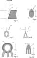
- Fig. 9 illustrates the shape of the liquid-carrying tube to be oval/elliptical.
- Figure 8 shows an alternative shape of the liquid-carrying tube, namely triangular.
- Figure 9 yet shows an embodiment in which the mobile protection structure has cooling fins 93 extending downwardly from a body of the mobile protection structure.
- cooling fins 93 in Fig. 9 are illustrated to extend parallel to the longitudinal dimension (x-dimension). However, generally, cooling fins could also extend in the y-dimension so that a movement of the mobile protection structure, being a movement in the plus or minus y-direction, causes a flow of air between the cooling fins 93. Also other shapes of surface-enhancing cooling structures are possible, for example a structure with a plurality of pin-like extensions extending downwardly.
- the mobile protection structure is illustrated to have a hollow, thus tube-like body 91 of a first material, with the cooling fins being one-piece with the body and also being of the first material, and a coating 92 of a second material, similar to the embodiment of Fig. 6 .
- a hollow-tube like structure in contrast to rod-like structures, has the advantage of being lighter.
- the tube-like structure of the body 91 may optionally also be used for the mobile protection structure to serve as liquid-carrying tube for a coolant, as in the above-described embodiments, for example if the laser cutting machine is operated at high power. This, however, is not a necessity.
- FIG. 10 illustrates a cross section through a mobile protection structure 90 implementing the principles described hereinbefore referring to Fig. 6 and in addition comprising cooling fins 93.
Landscapes
- Engineering & Computer Science (AREA)
- Physics & Mathematics (AREA)
- Optics & Photonics (AREA)
- Mechanical Engineering (AREA)
- Plasma & Fusion (AREA)
- Laser Beam Processing (AREA)
Abstract
Description
- The invention is in the field of flatbed laser cutting machines.
- Flatbed laser cutting machines comprise a workpiece support that defines a usually horizontal area of support and thereon supports a workpiece, which may for example be a sheet or plate of a material to be cut. The flatbed laser cutting machine further comprises a laser cutting head that is equipped to emit a laser cutting beam having a direction perpendicular to the area of support. The laser cutting head is equipped to move at least in two horizontal directions relative to the workpiece support to make the desired cut.
- More recently, the need for ever greater laser powers, exceeding, for example by far exceeding, 1 kW seems to be increasing strongly. However, it can be observed that only a small part of the laser light power is actually coupled into the workpiece so as to locally melt or burn workpiece material. The rest of the laser radiation is directed to other parts of the machine or its surrounding and has a potential of causing damages. Especially, the machine base, i.e., the frame and/or other parts below the workpiece and the floor underneath the flatbed laser cutting machine need to be protected from being damaged by the laser cutting beam - which is by no means a trivial task for a laser beam that is capable of cutting through workpieces of substantial thickness of for example 10 mm and more.
- It is an object of the present invention to provide a flatbed laser cutting machine overcoming drawbacks of previous flatbed laser cutting machines. Especially, it is an object of the present invention to provide a flatbed laser cutting machine that has an improved protection from damages caused by unused radiation portions when operated at high powers.
- This object is achieved by a flatbed laser cutting machine having a workpiece support defining a horizontal area of support for a workpiece, for example a sheet metal or a metal plate, to lie thereon. The flatbed laser cutting machine further comprises a laser cutting head equipped to emit a laser cutting beam towards a workpiece supported by the workpiece support, for example in a direction essentially perpendicular to the area of support. The laser cutting head is placed above the area of support and is equipped to be moved in horizontal directions, generally with two degrees of freedom (i.e., the laser cutting head can move in x and y directions if the z direction is defined to be the direction of the laser beam). Underneath the area of support, the laser cutting machine comprises a machine base. The flatbed laser cutting machine further comprises a mobile protection structure between the area of support and the machine base, the mobile protection structure being coupled to the laser cutting head to join in movements of the laser cutting head.
- Radiation energy that impinges on the workpiece is either absorbed or reflected by the workpiece. Only absorbed radiation can locally heat the workpiece and contribute to the cutting effect. Many materials to be cut are metals, which often have a high reflectance, whereby the portion of reflected radiation is high. One insight underlying the invention is that, for reasons explained in more detail hereinafter, the majority of the reflected radiation is reflected into a downward direction - the thicker the workpiece, the higher the portion of radiation reflected into the downward direction. Also, the thicker the workpiece is, the closer the direction into which the radiation is reflected is to the vertical. Further, the thicker the workpiece, the smaller the portion of radiation that is absorbed. Moreover, in reality, the speed by which the laser beam moves relative to the workpiece does not correspond to an ideal but is smaller than this so that a portion of the laser radiation does not interact with the workpiece at all but propagates straight downwardly.
- The flatbed laser cutting machine as described in this text may be equipped for emitting a laser having a power of at least 1 kW, especially at least 5 kW or at least 10 kW.
- High power laser cutting machines are especially used for cutting thick workpieces. Thus, the above insights reveal that for high power laser cutting machines, there will not only be more power, but also the share of the residual power that is unused and radiated downwardly to below the area of support is higher.
- Based in this insight, the present invention proposes to protect the machine base underneath the area of support by the mobile protection structure that is coupled to the laser cutting head to join in movements of the laser cutting head.
- The coupling between the laser cutting head and the mobile protection structure may be a mechanical coupling. For example, the mobile protection structure may be mechanically coupled to a bridge that moves relative to the workpiece in one horizontal dimension and relative to which the laser cutting head moves in another horizontal dimension, as explained hereinafter in more detail. In addition or as an alternative to being mechanically coupled, the mobile protection structure may be coupled to the laser cutting head in a different way. For example, the mobile protection structure may have its own drive that moves synchronously with at least some of the movements of the laser cutting head, the coupling then being a coupling implemented by electronics. Also other kinds of coupling between the laser cutting head and the mobile protection structure, for example via a hydraulic or pneumatic drive or similar, are possible.
- The mobile protection structure is positioned in a path of downwards (into -z-direction, thus vertically downwards) radiated laser radiation so that it will be hit by this radiation.
- By being mobile and cooperating in at least some of the movements of the laser cutting head, the mobile protection structure is not necessarily as extended as the working area but may be comparably light, and it may be suitable to be integrated in existing designs of existing flatbed laser cutting machines.
- For example, the mobile protection structure may have a generally elongate shape substantially extending over a full width of the area of support with respect to one (first) horizontal dimension. The mobile protection structure then may be coupled to the laser cutting head to join in the laser cutting head's movements with respect another, second horizontal dimension orthogonal to the first horizontal dimension.
- Especially, the flatbed laser cutting machine may comprise a bridge on which the laser cutting head is mounted and relative to which the laser cutting head may move in first horizontal directions (plus or minus x-directions), i.e. along a first horizontal dimension (x-dimension). The bridge as a whole is movable relative to the workpiece support in second horizontal directions (plus or minus y-directions), i.e. along a second horizontal dimension (y-dimension). This is a construction that is per se common for flatbed laser cutting machines. In accordance with embodiments, the mobile protection structure is coupled to the bridge and moves together with the bridge in the y dimensions, i.e. in the y direction or -y-direction. It may have an extension in the first horizontal dimension that may approximately correspond to the extension of the bridge in this dimension or, be more precise, to the extension of the range in which the laser cutting head may be moved on the bridge/relative to the bridge.
- The mobile protection structure may comprise means for distributing heat - for example over a length of the mobile protection structure (for example referring to the first horizontal dimension) - and/or for dissipating heat.
- Means for distributing heat may especially comprise a heat conductor. In an example, the mobile protection structure comprises a rod or tube extending along a horizontal dimension (the first horizontal dimension (x-dimension) in the described embodiment) and being of a first material that efficiently conducts heat, such as aluminum, steel or another efficient heat conductor. On the upper side, the mobile protection structure may comprise a second material that has a high heat resistance, such as ceramics, so that wear caused by the laser radiation is delayed as much as possible.
- The latter may comprise passive cooling structures, such as cooling fins or similar. In addition or as an alternative, means for distributing heat may comprise an active cooling.
- In embodiments, the mobile protection structure is a sacrificial part that may be relatively inexpensive and for example be a - possibly coated - rod-like or tube-like body, for example of aluminum or steel. The cross section of such body may be regular, for example simply round or rectangular - or may be irregular and/or optimized for cutting waste to not stick, as explained in somewhat more detail hereinafter.
- At least in embodiments in which the mobile protection structure is such a - usually not actively cooled - sacrificial part, the mobile protection structure needs to be replaced every now and then. To this end, the flatbed laser cutting machine may be equipped for the mobile protection structure to be exchangeable easily, for example by providing an according mechanical interface to which the mobile protection structure is attached - such as a click-in connector, a bayonet coupling, a screw interface, etc. Such mechanical interface makes a replacement of the mobile protection structure as a low cost-replacement part easy.
- In embodiments, the mobile protection structure is cooled in that the cooling installation is equipped to convey a coolant (i.e., a cooling liquid or possibly a cooling gas, thus generally a cooling fluid) to the mobile protection structure and away from it so that there is a coolant flow.
- Especially, in such embodiments, the (mobile) protection structure may comprise a liquid-carrying tube that carries the coolant. The tube may lie essentially parallel to the x-axis and move with the bridge in the y-dimension.
- In embodiments, such a mobile protection structure, especially extending in the first horizontal dimension, has a cross section different from circular. Especially, the cross section may be optimized for cutting waste to not stick relative to the mobile protection structure. It may for example run into an edge on the upper side (thus, a corner in cross section perpendicular to the longitudinal extension of the liquid-carrying tube. In addition or as an alternative, the horizontal dimension in cross section (the y-dimension in the above example, the cross section again being the cross section perpendicular to the longitudinal extension, for example corresponding to a cross section in the y-z plane) may be smaller than the vertical extension.
- The mobile protection structure in the above-mentioned embodiments is configured to absorb residual radiation, thus radiation that was not absorbed by the workpiece-. In addition, the mobile protection structure may act to spread portions of the residual radiation that are not absorbed into the environment so that in contrast to set-ups without the mobile protection structure, there are no high concentrations of laser radiation below the workpiece support and consequently no hot spots are generated. Surface portions of the protection structure may be equipped accordingly, for example by having a chemical composition that favors absorption of radiation of the wavelength of the laser beam, and/or by having an according structure, for example an according roughness.
- In addition to absorbing the residual laser radiation, the mobile protection structure may comprise reflecting surface portions directing radiation portions to absorbing elements. Such absorbing elements may - but do not necessarily need to - be placed below the area of support, too.
- In embodiments that comprise active cooling by a coolant, it is possible that the heat aggregated in the coolant is used for energy recovery, for example by the coolant being in contact with a thermoelectric converter generating electricity, by the heated coolant being supplied to a thermal engine, or by a thermal contact with a secondary heat exchange fluid that is for example supplied to a heat accumulator, etc. It is also not excluded that the absorbing elements of the cooling installation are equipped to directly convert a part of the radiation energy into electrical energy, by comprising photovoltaic cells.
- Hereinafter, embodiments of the present invention are described in more detail referring to drawings. In the drawings, same reference numbers refer to same or similar components. They show:
- Fig. 1:
- a flatbed laser cutting machine;
- Fig. 2
- a cross section through the workpiece at the cutting front;
- Fig. 3
- absorption coefficients of steel for unpolarized light as a function of the angle of incidence;
- Fig. 4
- a cross section corresponding to the cross section of
Fig. 2 for a non-ideal situation; - Fig. 5
- a flatbed laser cutting machine with a mobile protection structure for protecting the machine base;
- Fig. 6
- a cross section of a mobile protection structure;
- Figs. 7 and 8
- cross sections of liquid-carrying tubes as mobile protection structures; and
- Figs. 9 and 10
- cross sections of further mobile protection structures.
-
Figure 1 shows an example of alaser cutting machine 1. The machine comprises alaser source 201, atransport fiber 212, alaser cutting head 210, and a laser processing head moving mechanism. Aworkpiece 5 is supported by a workpiece support (not shown inFig. 1 ). The laser cutting head moving mechanism comprises abridge 202 relative to which thelaser cutting head 210 is movable in the x dimension), and which itself is movable, for example on a pair or rails, in the y dimension relative to the working table and theworkpiece 5. Thelaser cutting head 210 during operation emits alaser cutting beam 3 in a substantially vertical direction downwards onto the workpiece to cause a cut (kerf 51) when it is moved relative to the latter. Theworkpiece 5 may be a metal plate that is cut by a laser processing beam emitted by the laser cutting head. - During a laser cutting operation, movements with high velocities and high accelerations have to be made in a machining area both, in x and y directions. Movements in the y dimension involve moving the
entire bridge 202 together with the head. - Even though the laser beam impinges from a direction perpendicular to the area of support (which is defined by the working table and in the depicted embodiment corresponds to the lower surface of the plate-shaped workpiece 5) and hence to the upper surface of the workpiece, the angle of incidence is much larger than 0°.
Figure 2 illustrates the cuttingfront 53 as thelaser cutting beam 3 moves in a cuttingdirection 54 relative to theworkpiece 5. As can be seen fromFig. 2 , the minimum angle of incidence is
- The absorption coefficient is a material property and describes how much light energy can be absorbed by the material. The degree of absorption depends on the angle of incidence, the wavelength and the polarisation, in addition to material properties.
Figure 3 shows the approximate absorption coefficient A of steel for unpolarised (or circularly polarised) light at wavelengths of 1 and 10 µm as a function of the angle of incidence α. Obviously, the degree of absorption at angles of incidence such as those encountered in laser cutting is small, especially at the wavelength of 1µm, and it is always less than 40%. Especially with the increasingly powerful lasers, mainly very thick materials are cut, whereby consequently only a small part of the laser power of significantly less than 10% is absorbed. The rest is reflected. According to the law of reflection and given that the cuttingfront 53 is close to vertical, the non-absorbed laser light shares essentially go downwards. - In practice, however, the minimum angle of incidence, which is theoretically optimal will not be encountered. The typical cutting process is much more like the one shown in
Figure 4 , where a share of the laser beam is radiated downwards towards the bottom without interaction with the cuttingfront 53 and the angle of incidence α is even larger than αmin. This means that the energy yield available for the separation process is even lower, and that the share of radiation energy radiated downwardly from the area of support is even higher, the direction being vertical (radiation that does not interact with the workpiece) or almost vertical (radiation reflected by the cutting front), thus essentially vertical. -
Figure 5 a cross-section of a flatbed laser cutting machine of the kind commonly used today for laser cutting of metal sheets. More in particular, it illustrates an embodiment of the present invention, namely a flatbedlaser cutting machine 1 with a mobile protection structure. - The workpiece support is formed by a
support grid 14. Thesupport grid 14 with theworkpiece 5 lies horizontally under thelaser processing head 210 here illustrated with anozzle 211 for ejecting a gas jet onto the position of incidence of the laser beam on theworkpiece 5. The machine base below thesupport grid 14 comprises optional mobile trolleys 4 into which the cutting waste falls. - The bridge 202 (see also
Fig. 1 ) is coupled to amobile protection structure 90. Themobile protection structure 90 may be essentially tube-shaped or rod-shaped. It extends underneath thebridge 202, having a same y position as the bridge, and it extends along a full length of the range on which thelaser cutting head 210 may be moved on thebridge 202. - In embodiments, the
mobile protection structure 90 is a rod of a material that is capable of withstanding the wear caused by the impinging laser energy for at least some time and/or that is capable of conducting heat away along the length of the rod, thus in the x-dimension. - The
mobile protection structure 90 may be a sacrificial part that needs to be replaced every now and then because the laser radiation may cause damages. -
Figure 6 depicts a cross section through an exemplary embodiment of a rod-likemobile protection structure 90. The structure of the embodiment ofFig. 6 deviates from the structure of a plain rod by having the following features, which can be realized independent of each other, thus individually, in combination, or in any subcombination. - In the cross-section perpendicular to the length axis of the mobile protection structure (thus to the x-axis), the horizontal dimension (the y-dimension) is smaller than the vertical dimension (the z-dimension). This is to falling parts and other cutting waste to not stick but to fall to the bottom.
- The cross section is pointed towards the upper side, again with the purpose of preventing cutting waste from sticking to the mobile protection structure.
- The mobile protection structure comprises a
body 91 of a first material, which may for example be a good heat conductor, such as aluminum, and, on the upper side, on which the radiation impinges, acoating 92 of a second material different from the first material. The second material in this may be a material that is heat resistant, such as ceramics. -
Figures 7 and 8 show embodiments of themobile protection structure 90 in which the mobile protection structure is a liquid-carrying tube capable of conducting a cooling liquid. - A cross-section of a first embodiment of a
mobile protection structure 90 being a liquid-carrying tube is shown inFigure 7 . The heat generated by the laser radiation impinging on themobile protection structure 90 thereby can be constantly conveyed away from the position of incidence of the laser radiation. This may especially be advantageous in situations in which the x-position of the laser cutting head remains constant for a certain time during cutting (for example when a cut parallel to the x-axis is made) and/or if the heat is to be used, for example for energy recovery in the form of generation of electrical power or for heating purposes. - The features described hereinbefore referring to
Fig. 6 can also be implemented in embodiments in which the mobile protection structure is not a rod but a tube, with the possibility to conduct a liquid.Fig. 9 illustrates the shape of the liquid-carrying tube to be oval/elliptical.Figure 8 shows an alternative shape of the liquid-carrying tube, namely triangular. -
Figure 9 yet shows an embodiment in which the mobile protection structure has coolingfins 93 extending downwardly from a body of the mobile protection structure. - The cooling
fins 93 inFig. 9 are illustrated to extend parallel to the longitudinal dimension (x-dimension). However, generally, cooling fins could also extend in the y-dimension so that a movement of the mobile protection structure, being a movement in the plus or minus y-direction, causes a flow of air between the coolingfins 93. Also other shapes of surface-enhancing cooling structures are possible, for example a structure with a plurality of pin-like extensions extending downwardly. - In
Fig. 9 , the mobile protection structure is illustrated to have a hollow, thus tube-like body 91 of a first material, with the cooling fins being one-piece with the body and also being of the first material, and acoating 92 of a second material, similar to the embodiment ofFig. 6 . A hollow-tube like structure, in contrast to rod-like structures, has the advantage of being lighter. The tube-like structure of thebody 91 may optionally also be used for the mobile protection structure to serve as liquid-carrying tube for a coolant, as in the above-described embodiments, for example if the laser cutting machine is operated at high power. This, however, is not a necessity. -
Figure 10 , finally, illustrates a cross section through amobile protection structure 90 implementing the principles described hereinbefore referring toFig. 6 and in addition comprisingcooling fins 93. - Various other embodiments may be envisaged.
Claims (12)
- A flatbed laser cutting machine (1), having a machine base and a workpiece support defining, above the machine base, a horizontal area of support for a workpiece (5), the flatbed laser cutting machine further comprising a laser cutting head (210) placed above the area of support and equipped to emit a laser cutting beam (3) towards a workpiece supported by the workpiece support and to be moved in horizontal directions relative to the workpiece (5) and the workpiece support, characterized by mobile protection structure (90) between the area of support and the machine base, the mobile protection structure being coupled to the laser cutting head to join in movements of the laser cutting head.
- The flatbed laser cutting machine of claim 1, wherein the mobile protection structure is positioned below the area of support, in a path of radiation radiated by the laser cutting head (210) vertically downwards through the area of support.
- The flatbed laser cutting machine of claim 1 or 2, wherein the mobile protection structure (90) has a generally elongate shape substantially extending over a full width of the area of support with respect to a first horizontal dimension (x), and wherein the mobile protection structure is coupled to the laser cutting head to join in the laser cutting head's movements with respect to another, second horizontal dimension (y) orthogonal to the first horizontal dimension (x).
- The flatbed laser cutting machine of any one of the previous claims, comprising a bridge (202) on which the laser cutting head (210) is mounted and relative to which the laser cutting head is movable in a first horizontal dimension (x), the bridge being movable relative to the workpiece support in a second horizontal dimension (y) different from the first horizontal dimension, wherein the mobile protection structure is movable in the second horizontal dimension (y) together with the bridge (202).
- The flatbed laser cutting machine of any one of the previous claims, wherein the mobile protection structure (90) comprises a rod or tube extending, underneath the area of support, along a horizontal dimension.
- The flatbed laser cutting machine of any one of the previous claims, wherein the mobile protection structure comprises a body (91) of a first material and, at least on its side facing the laser beam, a coating (92) of a second material, wherein the second material has a higher heat resistance than the first material.
- The flatbed laser cutting machine of claim 6, wherein the first material is a metal, such as steel or aluminum, and the second material is a ceramic.
- The flatbed laser cutting machine of any one of the previous claims, wherein the mobile protection structure comprises passive cooling structures.
- The flatbed laser cutting machine of any one of the previous claims, wherein the mobile protection structure comprises a liquid-carrying tube (90) for a coolant.
- The flatbed laser cutting machine of any one of the previous claims, wherein the mobile protection structure has a cross section different from circular, wherein at least one of the following conditions holds: the cross section is pointed towards the upper side; in a cross section the horizontal dimension is smaller than the vertical dimension.
- The flatbed laser cutting machine of any one of the previous claims being configured for the mobile protection structure being exchangeable.
- The flatbed laser cutting machine of any one of the previous claims, wherein the mobile protection structure comprises a rod-like or tube-like body of aluminum or steel.
Priority Applications (1)
| Application Number | Priority Date | Filing Date | Title |
|---|---|---|---|
| EP23185119.7A EP4491318A1 (en) | 2023-07-12 | 2023-07-12 | Flatbed laser cutting machine |
Applications Claiming Priority (1)
| Application Number | Priority Date | Filing Date | Title |
|---|---|---|---|
| EP23185119.7A EP4491318A1 (en) | 2023-07-12 | 2023-07-12 | Flatbed laser cutting machine |
Publications (1)
| Publication Number | Publication Date |
|---|---|
| EP4491318A1 true EP4491318A1 (en) | 2025-01-15 |
Family
ID=87280807
Family Applications (1)
| Application Number | Title | Priority Date | Filing Date |
|---|---|---|---|
| EP23185119.7A Pending EP4491318A1 (en) | 2023-07-12 | 2023-07-12 | Flatbed laser cutting machine |
Country Status (1)
| Country | Link |
|---|---|
| EP (1) | EP4491318A1 (en) |
Citations (5)
| Publication number | Priority date | Publication date | Assignee | Title |
|---|---|---|---|---|
| WO2007028576A2 (en) * | 2005-09-06 | 2007-03-15 | Trumpf Werkzeugmaschinen Gmbh + Co. Kg | Beam catching device for a processing machine |
| US20100064870A1 (en) * | 2008-09-18 | 2010-03-18 | Omax Corporation | Fluid jet cutting system with bed slat caps |
| EP2164672B1 (en) * | 2007-06-14 | 2015-05-06 | TRUMPF Werkzeugmaschinen GmbH + Co. KG | Method for detecting a process light during a separation process in sheet material and device for carrying out the method |
| CN218695002U (en) * | 2022-08-18 | 2023-03-24 | 深圳美克激光设备有限公司 | Integrative laser cutting machine of dust removal template pipe |
| EP4183515A1 (en) * | 2021-11-23 | 2023-05-24 | Bystronic Laser AG | Laser cutting machine |
-
2023
- 2023-07-12 EP EP23185119.7A patent/EP4491318A1/en active Pending
Patent Citations (5)
| Publication number | Priority date | Publication date | Assignee | Title |
|---|---|---|---|---|
| WO2007028576A2 (en) * | 2005-09-06 | 2007-03-15 | Trumpf Werkzeugmaschinen Gmbh + Co. Kg | Beam catching device for a processing machine |
| EP2164672B1 (en) * | 2007-06-14 | 2015-05-06 | TRUMPF Werkzeugmaschinen GmbH + Co. KG | Method for detecting a process light during a separation process in sheet material and device for carrying out the method |
| US20100064870A1 (en) * | 2008-09-18 | 2010-03-18 | Omax Corporation | Fluid jet cutting system with bed slat caps |
| EP4183515A1 (en) * | 2021-11-23 | 2023-05-24 | Bystronic Laser AG | Laser cutting machine |
| CN218695002U (en) * | 2022-08-18 | 2023-03-24 | 深圳美克激光设备有限公司 | Integrative laser cutting machine of dust removal template pipe |
Similar Documents
| Publication | Publication Date | Title |
|---|---|---|
| EP1500484B1 (en) | Method and system for machining fragile material | |
| CN111151896B (en) | A method for cutting a solar cell | |
| US20140113797A1 (en) | Device and method for cutting brittle member and cut-out brittle member | |
| KR102428350B1 (en) | Substrate processing station for laser-based machining of sheet-like glass substrates | |
| JP6705827B2 (en) | Laser processing method and laser processing apparatus | |
| US20150209911A1 (en) | Cutting device | |
| JP6546207B2 (en) | Laser processing method | |
| CN209985921U (en) | Inner pipe wall laser cleaning equipment | |
| US20080067159A1 (en) | Laser processing system and method for material processing | |
| JP2005212364A (en) | Brittle material cleaving system and method | |
| CN113714656B (en) | Cell cutting device and cutting method | |
| US10044161B2 (en) | Heat exchangers with tapered light scrapers for high-power laser systems and other systems | |
| Mak et al. | Liquid-immersion laser micromachining of GaN grown on sapphire | |
| KR20130126287A (en) | Substrate cutting and method | |
| WO2001038038A3 (en) | Device for a laser hybrid welding process | |
| RU2001103674A (en) | ELECTRON BEAM RADIATION DEVICE | |
| KR100660221B1 (en) | Butt welding device and method | |
| CN220462230U (en) | Metal 3D printing equipment | |
| EP4491317A1 (en) | Flatbed laser cutting machine with an energy collection device | |
| CN105855701A (en) | Workbench of fiber laser cutting machine | |
| Dorsch et al. | 2-kW cw fiber-coupled diode laser system | |
| JP2010253498A (en) | Laser processing machine and its scattered matter collection method | |
| EP4234150B1 (en) | Laser cutting method | |
| CN211708429U (en) | Take self preservation to protect high power laser cutting machine welded joint of function | |
| KR102807317B1 (en) | 15mm welding bead width three-wire type smart fiber laser welding device and method |
Legal Events
| Date | Code | Title | Description |
|---|---|---|---|
| PUAI | Public reference made under article 153(3) epc to a published international application that has entered the european phase |
Free format text: ORIGINAL CODE: 0009012 |
|
| STAA | Information on the status of an ep patent application or granted ep patent |
Free format text: STATUS: THE APPLICATION HAS BEEN PUBLISHED |
|
| AK | Designated contracting states |
Kind code of ref document: A1 Designated state(s): AL AT BE BG CH CY CZ DE DK EE ES FI FR GB GR HR HU IE IS IT LI LT LU LV MC ME MK MT NL NO PL PT RO RS SE SI SK SM TR |
|
| STAA | Information on the status of an ep patent application or granted ep patent |
Free format text: STATUS: REQUEST FOR EXAMINATION WAS MADE |
|
| 17P | Request for examination filed |
Effective date: 20250701 |
|
| STAA | Information on the status of an ep patent application or granted ep patent |
Free format text: STATUS: EXAMINATION IS IN PROGRESS |
|
| 17Q | First examination report despatched |
Effective date: 20260205 |