EP4491305A1 - Housing assembly for rotary engine - Google Patents
Housing assembly for rotary engine Download PDFInfo
- Publication number
- EP4491305A1 EP4491305A1 EP24188369.3A EP24188369A EP4491305A1 EP 4491305 A1 EP4491305 A1 EP 4491305A1 EP 24188369 A EP24188369 A EP 24188369A EP 4491305 A1 EP4491305 A1 EP 4491305A1
- Authority
- EP
- European Patent Office
- Prior art keywords
- housing
- rotor
- face
- alloy
- base material
- Prior art date
- Legal status (The legal status is an assumption and is not a legal conclusion. Google has not performed a legal analysis and makes no representation as to the accuracy of the status listed.)
- Pending
Links
Images




Classifications
-
- F—MECHANICAL ENGINEERING; LIGHTING; HEATING; WEAPONS; BLASTING
- F02—COMBUSTION ENGINES; HOT-GAS OR COMBUSTION-PRODUCT ENGINE PLANTS
- F02B—INTERNAL-COMBUSTION PISTON ENGINES; COMBUSTION ENGINES IN GENERAL
- F02B55/00—Internal-combustion aspects of rotary pistons; Outer members for co-operation with rotary pistons
- F02B55/08—Outer members for co-operation with rotary pistons; Casings
-
- F—MECHANICAL ENGINEERING; LIGHTING; HEATING; WEAPONS; BLASTING
- F01—MACHINES OR ENGINES IN GENERAL; ENGINE PLANTS IN GENERAL; STEAM ENGINES
- F01C—ROTARY-PISTON OR OSCILLATING-PISTON MACHINES OR ENGINES
- F01C1/00—Rotary-piston machines or engines
- F01C1/22—Rotary-piston machines or engines of internal-axis type with equidirectional movement of co-operating members at the points of engagement, or with one of the co-operating members being stationary, the inner member having more teeth or tooth- equivalents than the outer member
-
- B—PERFORMING OPERATIONS; TRANSPORTING
- B22—CASTING; POWDER METALLURGY
- B22F—WORKING METALLIC POWDER; MANUFACTURE OF ARTICLES FROM METALLIC POWDER; MAKING METALLIC POWDER; APPARATUS OR DEVICES SPECIALLY ADAPTED FOR METALLIC POWDER
- B22F10/00—Additive manufacturing of workpieces or articles from metallic powder
- B22F10/20—Direct sintering or melting
- B22F10/28—Powder bed fusion, e.g. selective laser melting [SLM] or electron beam melting [EBM]
-
- B—PERFORMING OPERATIONS; TRANSPORTING
- B22—CASTING; POWDER METALLURGY
- B22F—WORKING METALLIC POWDER; MANUFACTURE OF ARTICLES FROM METALLIC POWDER; MAKING METALLIC POWDER; APPARATUS OR DEVICES SPECIALLY ADAPTED FOR METALLIC POWDER
- B22F7/00—Manufacture of composite layers, workpieces, or articles, comprising metallic powder, by sintering the powder, with or without compacting wherein at least one part is obtained by sintering or compression
- B22F7/06—Manufacture of composite layers, workpieces, or articles, comprising metallic powder, by sintering the powder, with or without compacting wherein at least one part is obtained by sintering or compression of composite workpieces or articles from parts, e.g. to form tipped tools
- B22F7/08—Manufacture of composite layers, workpieces, or articles, comprising metallic powder, by sintering the powder, with or without compacting wherein at least one part is obtained by sintering or compression of composite workpieces or articles from parts, e.g. to form tipped tools with one or more parts not made from powder
-
- B—PERFORMING OPERATIONS; TRANSPORTING
- B33—ADDITIVE MANUFACTURING TECHNOLOGY
- B33Y—ADDITIVE MANUFACTURING, i.e. MANUFACTURING OF THREE-DIMENSIONAL [3D] OBJECTS BY ADDITIVE DEPOSITION, ADDITIVE AGGLOMERATION OR ADDITIVE LAYERING, e.g. BY 3D PRINTING, STEREOLITHOGRAPHY OR SELECTIVE LASER SINTERING
- B33Y10/00—Processes of additive manufacturing
-
- B—PERFORMING OPERATIONS; TRANSPORTING
- B33—ADDITIVE MANUFACTURING TECHNOLOGY
- B33Y—ADDITIVE MANUFACTURING, i.e. MANUFACTURING OF THREE-DIMENSIONAL [3D] OBJECTS BY ADDITIVE DEPOSITION, ADDITIVE AGGLOMERATION OR ADDITIVE LAYERING, e.g. BY 3D PRINTING, STEREOLITHOGRAPHY OR SELECTIVE LASER SINTERING
- B33Y30/00—Apparatus for additive manufacturing; Details thereof or accessories therefor
-
- B—PERFORMING OPERATIONS; TRANSPORTING
- B33—ADDITIVE MANUFACTURING TECHNOLOGY
- B33Y—ADDITIVE MANUFACTURING, i.e. MANUFACTURING OF THREE-DIMENSIONAL [3D] OBJECTS BY ADDITIVE DEPOSITION, ADDITIVE AGGLOMERATION OR ADDITIVE LAYERING, e.g. BY 3D PRINTING, STEREOLITHOGRAPHY OR SELECTIVE LASER SINTERING
- B33Y70/00—Materials specially adapted for additive manufacturing
-
- F—MECHANICAL ENGINEERING; LIGHTING; HEATING; WEAPONS; BLASTING
- F01—MACHINES OR ENGINES IN GENERAL; ENGINE PLANTS IN GENERAL; STEAM ENGINES
- F01C—ROTARY-PISTON OR OSCILLATING-PISTON MACHINES OR ENGINES
- F01C21/00—Component parts, details or accessories not provided for in groups F01C1/00 - F01C20/00
- F01C21/10—Outer members for co-operation with rotary pistons; Casings
-
- F—MECHANICAL ENGINEERING; LIGHTING; HEATING; WEAPONS; BLASTING
- F02—COMBUSTION ENGINES; HOT-GAS OR COMBUSTION-PRODUCT ENGINE PLANTS
- F02B—INTERNAL-COMBUSTION PISTON ENGINES; COMBUSTION ENGINES IN GENERAL
- F02B55/00—Internal-combustion aspects of rotary pistons; Outer members for co-operation with rotary pistons
-
- F—MECHANICAL ENGINEERING; LIGHTING; HEATING; WEAPONS; BLASTING
- F02—COMBUSTION ENGINES; HOT-GAS OR COMBUSTION-PRODUCT ENGINE PLANTS
- F02B—INTERNAL-COMBUSTION PISTON ENGINES; COMBUSTION ENGINES IN GENERAL
- F02B55/00—Internal-combustion aspects of rotary pistons; Outer members for co-operation with rotary pistons
- F02B55/14—Shapes or constructions of combustion chambers
-
- B—PERFORMING OPERATIONS; TRANSPORTING
- B22—CASTING; POWDER METALLURGY
- B22F—WORKING METALLIC POWDER; MANUFACTURE OF ARTICLES FROM METALLIC POWDER; MAKING METALLIC POWDER; APPARATUS OR DEVICES SPECIALLY ADAPTED FOR METALLIC POWDER
- B22F2207/00—Aspects of the compositions, gradients
- B22F2207/01—Composition gradients
-
- B—PERFORMING OPERATIONS; TRANSPORTING
- B22—CASTING; POWDER METALLURGY
- B22F—WORKING METALLIC POWDER; MANUFACTURE OF ARTICLES FROM METALLIC POWDER; MAKING METALLIC POWDER; APPARATUS OR DEVICES SPECIALLY ADAPTED FOR METALLIC POWDER
- B22F2999/00—Aspects linked to processes or compositions used in powder metallurgy
-
- B—PERFORMING OPERATIONS; TRANSPORTING
- B22—CASTING; POWDER METALLURGY
- B22F—WORKING METALLIC POWDER; MANUFACTURE OF ARTICLES FROM METALLIC POWDER; MAKING METALLIC POWDER; APPARATUS OR DEVICES SPECIALLY ADAPTED FOR METALLIC POWDER
- B22F5/00—Manufacture of workpieces or articles from metallic powder characterised by the special shape of the product
- B22F5/008—Manufacture of workpieces or articles from metallic powder characterised by the special shape of the product of engine cylinder parts or of piston parts other than piston rings
-
- B—PERFORMING OPERATIONS; TRANSPORTING
- B22—CASTING; POWDER METALLURGY
- B22F—WORKING METALLIC POWDER; MANUFACTURE OF ARTICLES FROM METALLIC POWDER; MAKING METALLIC POWDER; APPARATUS OR DEVICES SPECIALLY ADAPTED FOR METALLIC POWDER
- B22F5/00—Manufacture of workpieces or articles from metallic powder characterised by the special shape of the product
- B22F5/10—Manufacture of workpieces or articles from metallic powder characterised by the special shape of the product of articles with cavities or holes, not otherwise provided for in the preceding subgroups
- B22F5/106—Tube or ring forms
-
- B—PERFORMING OPERATIONS; TRANSPORTING
- B22—CASTING; POWDER METALLURGY
- B22F—WORKING METALLIC POWDER; MANUFACTURE OF ARTICLES FROM METALLIC POWDER; MAKING METALLIC POWDER; APPARATUS OR DEVICES SPECIALLY ADAPTED FOR METALLIC POWDER
- B22F7/00—Manufacture of composite layers, workpieces, or articles, comprising metallic powder, by sintering the powder, with or without compacting wherein at least one part is obtained by sintering or compression
- B22F7/06—Manufacture of composite layers, workpieces, or articles, comprising metallic powder, by sintering the powder, with or without compacting wherein at least one part is obtained by sintering or compression of composite workpieces or articles from parts, e.g. to form tipped tools
-
- F—MECHANICAL ENGINEERING; LIGHTING; HEATING; WEAPONS; BLASTING
- F01—MACHINES OR ENGINES IN GENERAL; ENGINE PLANTS IN GENERAL; STEAM ENGINES
- F01C—ROTARY-PISTON OR OSCILLATING-PISTON MACHINES OR ENGINES
- F01C21/00—Component parts, details or accessories not provided for in groups F01C1/00 - F01C20/00
- F01C21/06—Heating; Cooling; Heat insulation
-
- F—MECHANICAL ENGINEERING; LIGHTING; HEATING; WEAPONS; BLASTING
- F04—POSITIVE - DISPLACEMENT MACHINES FOR LIQUIDS; PUMPS FOR LIQUIDS OR ELASTIC FLUIDS
- F04C—ROTARY-PISTON, OR OSCILLATING-PISTON, POSITIVE-DISPLACEMENT MACHINES FOR LIQUIDS; ROTARY-PISTON, OR OSCILLATING-PISTON, POSITIVE-DISPLACEMENT PUMPS
- F04C2230/00—Manufacture
- F04C2230/90—Improving properties of machine parts
- F04C2230/92—Surface treatment
-
- F—MECHANICAL ENGINEERING; LIGHTING; HEATING; WEAPONS; BLASTING
- F05—INDEXING SCHEMES RELATING TO ENGINES OR PUMPS IN VARIOUS SUBCLASSES OF CLASSES F01-F04
- F05C—INDEXING SCHEME RELATING TO MATERIALS, MATERIAL PROPERTIES OR MATERIAL CHARACTERISTICS FOR MACHINES, ENGINES OR PUMPS OTHER THAN NON-POSITIVE-DISPLACEMENT MACHINES OR ENGINES
- F05C2201/00—Metals
- F05C2201/90—Alloys not otherwise provided for
- F05C2201/903—Aluminium alloy, e.g. AlCuMgPb F34,37
-
- F—MECHANICAL ENGINEERING; LIGHTING; HEATING; WEAPONS; BLASTING
- F05—INDEXING SCHEMES RELATING TO ENGINES OR PUMPS IN VARIOUS SUBCLASSES OF CLASSES F01-F04
- F05C—INDEXING SCHEME RELATING TO MATERIALS, MATERIAL PROPERTIES OR MATERIAL CHARACTERISTICS FOR MACHINES, ENGINES OR PUMPS OTHER THAN NON-POSITIVE-DISPLACEMENT MACHINES OR ENGINES
- F05C2251/00—Material properties
- F05C2251/10—Hardness
Definitions
- the application relates generally to aircraft engine and, more particularly, to rotary internal combustion engines and for housings thereof.
- Combustion chambers of a rotary engine are delimited radially by the rotor and rotor housing and axially by side housings.
- the side housings have faces oriented toward the combustion chambers and are thus subjected to high pressure and thermal loads.
- the side housings provide running surfaces for side seals of the rotor.
- a housing assembly for a rotary internal combustion engine comprising: a rotor housing extending around an axis, the rotor housing having a peripheral inner face facing a rotor cavity, a first face at a first side and a second face at a second side opposite to the first side; a first side housing secured to the first side of the rotor housing, the first side housing defining a first inner side face facing the rotor cavity and the rotor housing; and a second side housing secured to the second side of the rotor housing, the second side housing defining a second inner side face facing the rotor cavity and the rotor housing, the rotor cavity bounded axially between the first side housing and the second side housing, one or more of the rotor housing, the first side housing, and the second side housing having: a main body made of a base material; and an external layer made of an alloy including the base material, a wear-resistance of the alloy greater than that of the
- the housing assembly described above may include any of the following features, in any combinations.
- the main body and the external layer are monolithically connected to one another.
- the alloy has a hardness greater than that of the base material.
- the base material is aluminum and the alloy is aluminum-silicon-carbide.
- a thickness of the external layer is at least about 5 thousandths of an inch (0.127 mm).
- the thickness of the external layer is at most about 125 thousandths of an inch (3.175 mm).
- the external layer includes a transition layer extending from the main body.
- a ratio of a mass of the base material to a mass of the alloy by unit of volume gradually decreases within the transition layer from the main body.
- the rotor housing defines at least one cooling passage extending from the first face to the second face, the at least one cooling passage being countersunk at one or more of the first face and the second face.
- the first side housing includes a side wall secured to the rotor housing and a side plate, a peripheral section of the side plate disposed between the side wall and the rotor housing.
- the side plate is made of silicon carbide, the first inner side face extending around the side plate and abutting the first face of the rotor housing.
- both of the first inner side face and the first face are defined by the alloy.
- a rotary internal combustion engine including the housing assembly described above and a rotor received within the rotor cavity.
- a method of manufacturing a housing assembly for a rotary internal combustion engine comprising: obtaining a main body of one or more of the rotor housing and the two side housings, the main body made of a base material; and adding a layer of an alloy including the base material to the main body via additive manufacturing, the alloy being more wear-resistant than the base material, the layer defining a face either contacting another one of the one or more of the rotor housing and the two side housings or facing the rotor cavity.
- the method described above may include any of the following features, in any combinations.
- the method includes performing a machining step on the face to reach desired dimensions of the one or more of the rotor housing and the two side housings.
- the obtaining of the main body made of the base material includes obtaining the main body made of aluminum.
- the adding of the layer of the alloy includes adding a layer of aluminum-silicon-carbide.
- the adding of the layer of the alloy via additive manufacturing includes successively adding sub-layers on top of one another using a plurality of feedstock having a decreasing ratio of a mass of the base material to a mass of the alloy by unit of volume.
- the method includes obtaining cooling passages in the main body of the rotor housing before the adding of the layer of the alloy.
- the method includes countersinking the cooling passages before the adding of the layer of the alloy.
- a rotary internal combustion engine referred to simply as a rotary engine below, which may be a Wankel engine, is schematically shown at 10.
- the rotary engine 10 comprises an outer body also referred to as a housing assembly 12 having axially-spaced side housings 11, which each includes a side wall 14 and a side plate 16 mounted to the side wall 14, with a rotor housing 18 extending from one of the side housings 11 to the other, to form a rotor cavity 20.
- the rotor housing 18 has a first side and a second side opposite to the first side.
- the side housings 11 include a first side housing secured to the first side and a second side housing secured to the second side.
- the rotor cavity 20 is defined axially between the side housings 11 and circumscribed by the rotor housing 18.
- the side wall 14 is indicated with a dashed line because it sits below the side plate 16.
- the inner surface of the rotor housing 18 has a profile defining two lobes, which may be an epitrochoid.
- the side housings 11 include solely the side wall, that is, the side wall and the side plate may be combined into a single element.
- the housing assembly 12 includes a coolant circuit 12A, which may include a plurality of coolant conduits 18B defined within the rotor housing 18. As shown more clearly in Fig. 5 , the coolant conduits 18B extends from one of the side housings 11 to the other.
- the coolant circuit 12A is used for circulating a coolant, such as water or any suitable coolant, to cool the housing assembly 12 during operation of the rotary engine 10. Although only two coolant conduits 18B are shown, it is understood that more than two coolant conduits 18B may be used without departing from the scope of the present disclosure.
- An inner body or rotor 24 is received within the rotor cavity 20.
- the rotor 24 has axially spaced end faces 26 adjacent to the side walls 14, and a peripheral face 28 extending there between.
- the peripheral face 28 defines three circumferentially-spaced apex portions 30, and a generally triangular profile with outwardly arched sides 36.
- the apex portions 30 are in sealing engagement with the inner surface of rotor housing 18 to form three rotating combustion chambers 32 between the rotor 24 and housing assembly 12.
- the combustion chambers 32 vary in volume with rotation of the rotor 24 within the housing assembly 12.
- the geometrical axis of the rotor 24 is offset from and parallel to the axis of the housing assembly 12. In some embodiments, more or less than three rotating combustion chambers may be provided with other shapes of the rotor.
- each rotor apex portion 30 has an apex seal 52 extending from one end face 26 to the other and biased radially outwardly against the rotor housing 18.
- An end seal 54 engages each end of each apex seal 52 and is biased against the respective side wall 14.
- Each end face 26 of the rotor 24 has at least one arc-shaped face seal 60 running from each apex portion 30 to each adjacent apex portion 30, adjacent to but inwardly of the rotor periphery throughout its length, in sealing engagement with the end seal 54 adjacent each end thereof and biased into sealing engagement with the adjacent side plates 16 of the side housings 11. Alternate sealing arrangements are also possible.
- the rotor 24 is journaled on an eccentric portion of a shaft such that the shaft rotates the rotor 24 to perform orbital revolutions within the rotor cavity 20.
- the shaft may rotate three times for each complete rotation of the rotor 24 as it moves around the rotor cavity 20.
- Oil seals are provided around the eccentric to impede leakage flow of lubricating oil radially outwardly thereof between the respective rotor end face 26 and side housings 11.
- each chamber 32 varies in volumes and moves around the rotor cavity 20 to undergo the four phases of intake, compression, expansion and exhaust, these phases being similar to the strokes in a reciprocating-type internal combustion engine having a four-stroke cycle.
- the engine includes a primary inlet port 40 in communication with a source of air and an exhaust port 44
- the ports 40, 44 are defined in the rotor housing 18. Alternate configurations are possible.
- fuel such as kerosene (jet fuel) or other suitable fuel is delivered into the chamber 32 through a fuel port (not shown) such that the chamber 32 is stratified with a rich fuel-air mixture near the ignition source and a leaner mixture elsewhere, and the fuel-air mixture may be ignited within the housing using any suitable ignition system known in the art (e.g. spark plug, glow plug).
- the rotary engine 10 operates under the principle of the Miller or Atkinson cycle, with its compression ratio lower than its expansion ratio, through appropriate relative location of the primary inlet port 40 and exhaust port 44.
- the side housings 11 include the side walls 14 that are secured to the rotor housing 18.
- Each of the side walls 14 has a portion located proximate an outer perimeter P ( Fig. 4 ) of the side wall 14 and configured to be in abutment against the rotor housing 18 for defining the rotor cavity 20.
- each of the side walls 14 is configured to be secured to a respective one of opposed ends of the rotor housing 18.
- the side housings 11 further include side plates 16 located on inner sides of the side walls 14.
- the side plates 16 define rotor-engaging faces 16A on which the side seals 60 and the corner seals 54 of the rotor 24 are in abutment during rotation of the rotor 24.
- the side plates 16 further define back faces opposite the rotor-engaging faces 16A. The back faces of the side plates 16 face the side walls 14.
- the side walls 14 may be made of aluminum, more specifically an aluminum alloy, due to its light weight and high thermal conductivity. However, it may be required that the surfaces of the side walls 14 in contact with the seals 54, 60 be coated to provide a wear-resistance surface.
- the side plates 16 are made of aluminum and coated with a hard material such as silicon carbide, aluminum nitride, chromium carbide, tungsten carbide, and so on. Any suitable wear resistant coating applied by thermal spray or any other suitable method may be used.
- the side walls 14 and the side plates 16 will be described in more details below. Although the text below uses the singular form, the description may be applied to both of the side walls 14 and to both of the side plates 16.
- the side plates 16 may however be entirely made of the hard material, such as silicon carbide.
- the side plates 16 may be made of aluminum, steel, or any suitable ceramic material.
- the side wall 14 includes a peripheral section 14A, which is in abutment with the rotor housing 18, and a center section 14B, which is circumferentially surrounded by the peripheral section 14A.
- the peripheral section 14A of the side wall 14 is secured to the rotor housing 18.
- the center section 14B of one of the side walls 14 faces the center section 14B of the other of the side walls 14.
- the side walls 14 are secured to the rotor housing 18 with any suitable means known in the art.
- a sealing member 19 is located between the rotor housing 18 and the peripheral sections 14A of the side walls 14 for limiting coolant from leaking out.
- the sealing member 19 may be an O-ring.
- the sealing member 19 may be received within an annular recess, which may be defined by one or more of the rotor housing 18 and the side wall 14.
- the side wall 14 defines a recess 14C for receiving the side plate 16.
- the peripheral section 14A of the side wall 14 extends from the outer perimeter P to the recess 14C.
- a surface 14D of the peripheral section 14A of the side wall 14 that faces the rotor housing 18 is axially offset from a surface 14E of the center section 14B of the side wall 14.
- a magnitude of the offset corresponds to a depth of the recess 14C and may correspond to a thickness t of the side plate 16 plus any axial gap defined between a rotor-engaging face of the side plate 16 and the rotor housing 18.
- the side plate 16 is therefore in abutment with the surface 14E of the center section 14B of the side wall 14.
- a sealing surface of the side plate 16 located on a side of the side plate 16 that faces the rotor cavity, may be aligned with the peripheral section 14A of the side wall 14.
- the side wall 14 defines an abutment surface 14F.
- the abutment surface 14F is defined by a shoulder created by the offset of the surfaces 14D, 14E of the peripheral and central sections 14A, 14B of the side wall 14.
- the side plate 16 may be supported by a housing in the center to limit the movement of the side plate 16.
- a gap may remain between a peripheral section of the side plate 16 and the abutment surface 14F of the side wall 14.
- the side plate 16 may be spaced apart from the abutment surface 14F.
- a size of the gap may change during operation of the rotary engine 10 as the side wall 14 and the side plate 16 may expand at different rates with an increase of a temperature in the rotor cavity 20.
- the space between the side plate 16 and the abutment surface 14F of the side wall 14 may allow relative thermal expansion between the side plate 16 and the side wall 14 so that thermal stress transferred from the side plate 16 to the rotor housing 18 and the side wall 14 might be minimized.
- the seal 70 and the abutment surface 14F of the side wall 14 allows the side plate 16 to move radially relative to the side wall 14.
- Such a movement, along a radial direction relative to the axis of rotation of the rotor 24, may be required in a configuration in which the side wall 14 is made of a material having a coefficient of thermal expansion different than that of the side plate 16 and/or because the different components may be exposed to different temperatures and, thus may exhibit different thermal expansion.
- the side wall 14 further defines a pocket 14G that may circumferentially extend a full circumference of the side wall 14.
- the pocket 14G is annular. More than one pocket may be used.
- the pocket 14G may not cover an entirety of the center section 14B of the side wall 14.
- the pocket 14G is configured for circulating a liquid coolant, such as water for cooling the side plate 16.
- the pocket 14G may be part of the coolant circuit 12A and is in fluid flow communication with the coolant conduits 18B that are defined in the rotor housing 18.
- the pocket 14G extends from the surface 14E of the center section 14B and away from the rotor cavity 20.
- a depth D ( Fig. 5 ) of the pocket 14G is defined by a distance along the axis of rotation of the rotor 24 between the surface 14E of the center section 14B and a bottom surface 14H of the pocket 14G.
- the peripheral section 14A of the side wall 14 defines a plurality of ribs 14I that are circumferentially distributed around the rotor cavity 20.
- the ribs 14I defines the abutment surface 14F and a portion of the surface 14E of the center section 14B of the side wall 14. Consequently, and in the depicted embodiment, the abutment surface 14F is defined by a plurality of surfaces defined by the ribs 14I.
- the ribs 14I may be configured to support a pressure load imparted by a combustion of a mixture of air and fuel within the combustion chambers 32.
- Cavities or spaces 14J are defined between the ribs 14I. More specifically, each pair of two consecutive ones of the ribs 14I defines a space 14J therebetween.
- the spaces 14J are in fluid communication with the pocket 14G and with the coolant conduits 18B of the rotor housing 18. Stated otherwise, the coolant conduits 18B are in fluid communication with the pocket 14G via the spaces 14J between the ribs 14I.
- the spaces 14J may allow the liquid coolant to flow from the pocket 14G to the coolant conduits 18B of the rotor housing 18. It is understood that the liquid coolant may be circulated in closed loop and through a heat exchanger. The heat exchanger may be used to dissipate heat to an environment outside the engine; the heat transferred from the engine to the liquid coolant.
- a flow F1 of the liquid coolant circulates within the pocket 14G.
- the flow F1 is divided in sub-flows F2; each of the sub-flows F2 circulating within a respective one of the spaces 14J and within a respective one of the coolant conduits 18B of the coolant circuit 12A.
- the liquid coolant may be circulated out of the housing assembly 12 and within a heat exchanger for extracting the heat. The liquid coolant may then be reinjected in the coolant circuit 12A for further heat extraction.
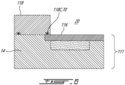
- FIG. 6 another embodiment of the outer body, more specifically of the side housing 111 and rotor housing 118, is generally shown. For the sake of conciseness, only elements that differ from the housing assembly 12 of Figs. 2-5 are described.
- the rotor housing 118 defines a groove 118C that receives the seal 70.
- the side housings of these rotary internal combustion engines are subjected to high pressure and thermal loads while having to provide running surface for the rotor. These running surfaces may be required to remain flat and cool to provide optimal sealing and to be of sufficient hardness to minimize wear.
- a material of choice for the rotor housing and the side housings may be aluminum due to its light weight and high thermal conductivity.
- the running surface of the aluminum housing may not be sufficiently wear-resistant.
- the surface between the side and rotor housing is subject to wear and fretting. It may be possible to alleviate this drawback by using a wear resistant aluminum, such as an aluminum-silicon-carbide alloy.
- a wear resistant aluminum such as an aluminum-silicon-carbide alloy.
- such a material is difficult to machine.
- a possible embodiment of a housing assembly at least partially alleviating the aforementioned drawbacks is shown at 200.
- the features described below with reference to Fig. 7 may be applied to any of the rotary internal combustion engines described in this disclosure.
- the housing assembly 200 includes a rotor housing 218 extending around axis A, which may correspond to a central axis of a crankshaft driven by the rotor 24 ( Fig. 1 ).
- the central axis A may correspond to a central axis of the rotor housing 218.
- the rotor housing 218 has a peripheral inner face 218A that extends around the axis A and that faces the rotor cavity 20.
- the rotor housing 218 has a first face 218B at a first side and a second face 218C at a second side opposite the first side.
- the peripheral inner face 218A extends from the first face 218B to the second face 218C.
- the housing assembly 200 includes a side housing 211.
- Fig. 7 only shows one side housing 211, another side housing is located on an opposite side of the rotor housing 218. It is not illustrated in Fig. 7 for clarity. The description below applies to both of the side housings.
- the side housing 211 is secured to the first side of the rotor housing 218 and defines a first inner face 211A facing the rotor cavity 20 and the rotor housing 218.
- the side housing 211 includes a side wall 214 and a side plate 216 as described above with reference to Figs. 4-6 .
- the first inner face 211A of the side housing 211 may therefore be defined conjointly by the side wall 214 and by the side plate 216. More specifically, the side wall 214 has an axial peripheral face 214A and the side plate 216 has an axial face 216A.
- the axial peripheral face 214A surrounds the axial face 216A of the side plate 216.
- the axial peripheral face 214A abuts the first face 218B of the rotor housing 218.
- the axial face 216A of the side plate 216 faces both of the first face 218B of the rotor housing 218 and the rotor cavity 20.
- the axial face 216A of the side plate 216 may be distanced from the first face 218B of the rotor housing 218 by a gap.
- the rotor housing 218 has a main body 218D and two external layers 218E disposed on opposite sides of the main body 218D.
- the main body 218D may thus be in between the two external layers 218E.
- the two external layers 218E define respectively the first face 218B and the second face 218C of the rotor housing 218.
- the main body 218D may be made of a base material whereas the external layers 218E may be made of an alloy including the base material.
- the expression "base material” may include an alloy.
- the base material may thus be itself an alloy, also referred to as a first alloy.
- the external layers 218E may therefore be made of a mixture, also referred to as a second alloy, between the first alloy of the base material and a reinforcement phase.
- the wear-resistance of the alloy is greater than that of the base material.
- the expression “wear-resistance” may imply that a hardness of the alloy is greater than a hardness of the base material.
- Wear-resistance refers to an ability of a material to resist wear either by friction with the rotor 24, by friction with the side housings 211, or any combinations of the above.
- the base material may be aluminum, such as 7075-T6, 2219-T6, or any equivalent, and the alloy may be an aluminum-based alloy.
- the alloy may be aluminum-silicon-carbide.
- the aluminum may be preferred for the rotor housing 218 because of its high thermal conductivity.
- the side housings 211 may be made of iron-based material for some applications where weight is less of a concern.
- the external layer may be a metal matrix composite (MMC). Another option may include the use of titanium diboride (TiB2) reinforcement.
- the external layer may be made of A205 aluminum.
- the external layer may be made of titanium diboride. These materials are contemplated for external layers of one or more of the rotor housing and the side housings.
- the rotor housing 218 may be made from iron-based alloy (e.g., steel, cast iron), with a more resistant layer at the interface.
- the main body 218D and the external layers 218E are monolithically connected to one another.
- the rotor housing 218 may be a single monolithic body that defines both of the main body 218D and the external layers 218E.
- a thickness of each of the external layers 218E may be at least about 5 thousandths of an inch (0.127 mm) and at most about 125 thousandths of an inch (3.175 mm). In some embodiments, the thickness is at least about 50 thousandths of an inch (1.27 mm) to about 100 thousandths of an inch (2.54). In this disclosure, the expression "about” implies variations of plus or minus 10%.
- the external layers 218E may each include a transition layer 218F, which is delimited with dashed lines in Fig. 7 , that extends from the main body 218D towards the first face 218B or the second face 218C of the rotor housing 218.
- a thickness of the transition layer 218F may be about 50% of a thickness of the external layer 218E.
- the transition layer 218F may be used to gradually transition the material of the rotor housing 218 from the base material to the alloy.
- a ratio of a mass of the base material to a mass of the alloy by unit of volume gradually decreases within the transition layer 218F from the main body 218D towards the first face 218B and the second face 218C of the rotor housing 218.
- the ratio may vary linearly within the transition layer 218F.
- the ratio may vary along any suitable transition (e.g., non-linear) to optimize part manufacturability and performance.
- the side housing 211 of this embodiment may also include a main body and an external layer. More specifically, the side wall 214 includes a main side body 214D and an external side layer 214E.
- the external side layer 214E defines the axial peripheral face 214A of the side wall 214.
- the axial peripheral face 214A is in abutment against the first face 218B of the rotor housing 218.
- the main side body 214D may be made of a base material whereas the external side layer 214E may be made of an alloy including the base material.
- the base material may be itself an alloy (e.g., the first alloy).
- the external side layer 214E may therefore be made of a mixture, also referred to as a second alloy, between the alloy of the base material and a reinforcement phase.
- the base material may be aluminum, such as 7075-T6, 2219-T6, or any equivalent, and the alloy may be an aluminum-based alloy.
- the alloy may be aluminum-silicon-carbide.
- the base material and the alloy used for the side wall 214 may differ than the base material and the alloy used for the rotor housing 218.
- the external side layer 214E may include a transition side layer 214F, which is delimited with dashed lines in Fig. 7 , and that extends from the main side body 214D towards the axial peripheral face 214A of the side wall 214.
- a thickness of the transition side layer 214F may be about 50% of a thickness of the external side layer 214E.
- the transition side layer 214F may be used to gradually transition the material of the side wall 214 from the base material to the alloy.
- a ratio of a mass of the base material to a mass of the alloy by unit of volume (e.g., cubic inch) gradually decreases within the transition side layer 214F from the main side body 214D towards the external side layer 214E. The ratio may vary linearly within the transition layer 214F.
- a remainder of the first inner face 211A of the side housing 211 may be defined by the side plate 216, which may be made of silicon carbide.
- the side plate 216 may be made entirely of silicon carbide and, thus, may not require the alloy used for the external layers of the side wall 214 and of the rotor housing 218 since the side plate 216 may be made of a material hard enough to resist wear during use (e.g., silicon carbide).
- the side plate 216 may thus be devoid of the alloy used for the side wall 214 and rotor housing 218.
- the side plate 216 may include a main body made of the base material and an external layer made of an alloy including the base material; the external layer defining the axial face 216A of the side plate 216.
- the rotor housing 218 may further include an external peripheral layer 218G extending from the main body 218D to the peripheral inner face 218A of the rotor housing 218.
- the external peripheral layer 218G may be made of the alloy being more resistant than the base material of the main body 218D of the rotor housing 218.
- the external peripheral layer 218G may be made of aluminum-silicon-carbide or any other equivalent material suitable to sustain the operating conditions in the combustion chambers of the rotary engine.
- the external peripheral layer 218G may include a transition peripheral layer 218H used to gradually transition the material of the rotor housing 218 from the base material of the main body 218D to the alloy.
- the rotor housing 218 may be devoid of the external layer of the allow at the peripheral inner face 218A and may instead be protected against wear via a thermal spray (HVOF) coating (e.g., very hard carbide).
- HVOF thermal spray
- FIG. 8 another embodiment of a housing assembly is shown at 300.
- Fig. 8 another embodiment of a housing assembly is shown at 300.
- Like reference numerals represent like features in Figs. 7 and 8 .
- the side housing 311 includes only a side wall 314 and is devoid of the side plate. Consequently, an entirety of a first inner face 311A of the side housing 311 is defined by the side wall 314.
- the first inner face 311A thus defines an axial peripheral face face 314A and an axial face 314B. These two faces are two distinct sections of the first inner face 311A of the side housing 311.
- the side wall 314 may include a main body 314D and an external layer 314E.
- the external layer 314E of the side wall 314 defines the first inner face 311A.
- the external layer 314E is therefore in abutment against the first face 218B of the rotor housing 218 and is exposed to the rotor cavity 20 for contacting the rotor 24 ( Fig. 1 ).
- the main body 314D may be made of a base material whereas the external layer 314E may be made of an alloy including the base material.
- a wear-resistance of the alloy is greater than that of the base material.
- the base material may be aluminum, such as 7075-T6, 2219-T6, or any equivalent, and the alloy may be an aluminum-based alloy.
- the alloy may be aluminum-silicon-carbide. Other suitable materials as listed above may be used.
- the main body 314D and the external layer 314E are monolithically connected to one another.
- the side wall 314 may be a single monolithic body that defines both of the main body 314D and the external layer 314E.
- a thickness of each of the external layer 314E may be at least about 5 thousandths of an inch (0.127 mm) and at most about 125 thousandths of an inch (3.175 mm), preferably from 50 to 100 thousandths of an inch (1.27 to 2.54 mm).
- the external layer 314E may each include a transition layer 314F, which is delimited with dashed lines in Fig. 8 , that extends from the main body 314D towards the first inner face 311A of the side housing 311.
- a thickness of the transition layer 314F may be about 50% of a thickness of the external layer 314E.
- the transition layer 314F may be used to gradually transition the material of the side wall 314 from the base material to the alloy.
- a ratio of a mass of the base material to a mass of the alloy by unit of volume e.g., cubic inch gradually decreases within the transition layer 314F from the main body 314D towards the external layer 314E. The ratio may vary linearly within the transition layer 314F.
- the rotor housing 218 may define a plurality of cooling passages.
- a cooling passage 218I is shown in Fig. 9 and extends from the first face 218B to the second face 218C. More detail about those cooling passages are presented below with reference to Fig. 5 .
- the cooling passage 218I may be countersunk at both of the first face 218B and the second face 218C. This may remove the alloy from the machining allowance of cooling passage 218I. This may reduce the wear on the tools.
- Fig. 9 shows an outlet of the cooling passage 218I before machining at 218J and after machining at 218K.
- the method 1000 includes obtaining a main body 218D, 214D, 314D of one or more of the rotor housing 218, and the two side housings 211, 311 the main body made of a base material at 1002; and adding a layer of an alloy including the base material to the main body 218D, 214D, 314D via additive manufacturing at 1004.
- the alloy is more wear-resistant than the base material.
- the alloy defines a face either contacting another one of the one or more of the rotor housing 218 and the two side housings 211, 311 or facing the rotor cavity 20.
- the method 1000 may include performing a machining step on the face to reach desired dimensions of the one or more of the rotor housing and the two side housings. This may include machining the alloy.
- the obtaining of the main body 218D, 214D, 314D at 1002 made of the base material includes obtaining the main body made of aluminum.
- the adding of the layer of the alloy at 1004 may include adding a layer of aluminum-silicon-carbide.
- the adding of the layer of the alloy via additive manufacturing at 1004 includes successively adding sub-layers on top of one another using a plurality of feedstock having a decreasing ratio of a mass of the base material to a mass of the alloy by unit of volume.
- the rotor housing and/or the side housings may be manufactured using Powder Bed Fusion (PBF), or any equivalent powder-based process.
- PPF Powder Bed Fusion
- the powder density may vary from 100% of the base material to 100% of the alloy.
- This transition layers described above may be made with an initial powder of 100% of the base material with a final powder of 100% of the alloy.
- the transition may be linear (50% base material and 50% alloy at the transition center), or any other suitable transition shape to optimize for stress, manufacturability or other constraints.
- the additive manufacturing process may create a near-finished surface.
- Final machining may be needed to achieve final dimensions and surface finish at some area such as coolant holes and datum surfaces.
- Final machining may be achieved using traditional subtractive manufacturing methods (e.g., drilling, milling, grinding, etc).
- the rotor housing and side housings may also be manufactured using Direct Energy Deposition, or any equivalent metal deposition process.
- a near-finished part made of the base material may be produced.
- the main production method may be machined from billet, cast or additive manufacturing other than DED.
- the alloy may be deposited on the running surfaces as a secondary operation. This process may be done for new parts, or for maintenance.
- the rotor and side housings may be created as a near-finished part using Direct Energy Deposition, or any equivalent process.
- the near-finished part may feature the bulk, base material and the wear resistant layer, referred to above as the alloy. Final machining may be achieved using traditional subtractive manufacturing methods.
- the parts may alternatively be manufactured using Ultrasonic Additive Manufacturing.
- a near-finished part made of the base material may be produced, either with other additive manufacturing process or using traditional subtractive manufacturing methods.
- This part may serve as base plate for the ultrasonic additive manufacturing.
- the alloy may be deposited in the form of a thin sheet on the running surfaces.
- the method 1000 may include machining the cooling passages 218I in the main body 218D of the rotor housing 218 before the adding of the layer of the alloy.
- the method may include obtaining the coolant passages 218I.
- the cooling passages may be obtained in the as-print housing.
- the method 1000 may include countersinking the cooling passages, from the base material through the transition layer, up to the interface.
- the countersunk in the reinforced layer being a continuation of the countersunk within the base material
- the countersunk in the external layers are a continuation of the countersunk in the main body.
- any machining operation in the housings may require going through the wear-resistant layer. Machining this feature might be difficult, costly, and it may render difficult to achieve the required tolerance or surface finish.
- the machine allowance material does not include wear-resistant material. Therefore, the manufacturing issues may be avoided. More specifically, it may be required to machine the internal surface of the cooling passage. Without the countersunk, a portion of this internal surface would be defined by the harder alloy, which may be difficult to machine.
- the dashed line in Fig. 9 illustrates a transition between the base material and the alloy; the harder alloy being above the dashed line.
- the present disclosure proposes using multi-material rotary engine housings.
- Soft, standard aluminum may constitute the bulk of the part (e.g., 50% or more of the mass of the part, preferably 75% or more of the mass of the part, preferably 90% or more of the weight of the part), with the wear resistant aluminum (e.g., the reinforced alloy) only applicable at the running surfaces or interfaces needing wear and fretting resistance.
- the bulk of the part may thus be easier to machine, which may allow most of the housings features to be produced without issues.
- the side housings 211 may include a bore 214B (shown schematically with a dashed line) for receiving a bearing.
- a wear resistant layer such as the alloy (e.g., aluminum-silicon-carbide) may be used to define a peripheral surface of the bore 214B.
- a steel bearing housing is usually press-fitted in the bore 214B. More specifically, the side housing defines the bore 214B for receiving the shaft.
- the shaft is rollingly supported by bearing(s), which include inner and outer races.
- the peripheral wall of this bore 214B may be defined by the alloy since it abuts the outer race of the bearing.
Landscapes
- Engineering & Computer Science (AREA)
- Chemical & Material Sciences (AREA)
- Mechanical Engineering (AREA)
- General Engineering & Computer Science (AREA)
- Manufacturing & Machinery (AREA)
- Materials Engineering (AREA)
- Combustion & Propulsion (AREA)
- Physics & Mathematics (AREA)
- Geometry (AREA)
- Composite Materials (AREA)
- Plasma & Fusion (AREA)
- Turbine Rotor Nozzle Sealing (AREA)
- Details And Applications Of Rotary Liquid Pumps (AREA)
- Laminated Bodies (AREA)
Abstract
A housing assembly (200) for a rotary engine, has: a rotor housing (218) having a peripheral inner face (218A) facing a rotor cavity (20), a first face (218B) and a second face (218C); a first side housing (211) secured to the first side (218B) and defining a first inner side face (211A); and a second side housing secured to the second side and defining a second inner side face, the rotor cavity (20) bounded axially between the first side housing (211) and the second side housing, one or more of the rotor housing (218), the first side housing (211), and the second side housing having: a main body (218D) made of a base material; and an external layer (218E) made of an alloy including the base material, a wear-resistance of the alloy greater than that of the base material, the external layer (218E) defining one or more of the first face (218B), the second face (218C), the first inner side face (211A), and the second inner side face.
Description
- The application relates generally to aircraft engine and, more particularly, to rotary internal combustion engines and for housings thereof.
- Combustion chambers of a rotary engine, such as a Wankel engine, are delimited radially by the rotor and rotor housing and axially by side housings. The side housings have faces oriented toward the combustion chambers and are thus subjected to high pressure and thermal loads. On the other hand, the side housings provide running surfaces for side seals of the rotor.
- According to one aspect of the present invention, there is provided a housing assembly for a rotary internal combustion engine, comprising: a rotor housing extending around an axis, the rotor housing having a peripheral inner face facing a rotor cavity, a first face at a first side and a second face at a second side opposite to the first side; a first side housing secured to the first side of the rotor housing, the first side housing defining a first inner side face facing the rotor cavity and the rotor housing; and a second side housing secured to the second side of the rotor housing, the second side housing defining a second inner side face facing the rotor cavity and the rotor housing, the rotor cavity bounded axially between the first side housing and the second side housing, one or more of the rotor housing, the first side housing, and the second side housing having: a main body made of a base material; and an external layer made of an alloy including the base material, a wear-resistance of the alloy greater than that of the base material, the external layer defining one or more of the first face of the rotor housing, the second face of the rotor housing, the first inner side face of the first side housing, and the second inner side face of the second side housing.
- The housing assembly described above may include any of the following features, in any combinations.
- Optionally, and in accordance with the above, the main body and the external layer are monolithically connected to one another.
- Optionally, and in accordance with any of the above, the alloy has a hardness greater than that of the base material.
- Optionally, and in accordance with any of the above, the base material is aluminum and the alloy is aluminum-silicon-carbide.
- Optionally, and in accordance with any of the above, a thickness of the external layer is at least about 5 thousandths of an inch (0.127 mm).
- Optionally, and in accordance with any of the above, the thickness of the external layer is at most about 125 thousandths of an inch (3.175 mm).
- Optionally, and in accordance with any of the above, the external layer includes a transition layer extending from the main body.
- Optionally, and in accordance with any of the above, a ratio of a mass of the base material to a mass of the alloy by unit of volume gradually decreases within the transition layer from the main body.
- Optionally, and in accordance with any of the above, the rotor housing defines at least one cooling passage extending from the first face to the second face, the at least one cooling passage being countersunk at one or more of the first face and the second face.
- Optionally, and in accordance with any of the above, the first side housing includes a side wall secured to the rotor housing and a side plate, a peripheral section of the side plate disposed between the side wall and the rotor housing.
- Optionally, and in accordance with any of the above, the side plate is made of silicon carbide, the first inner side face extending around the side plate and abutting the first face of the rotor housing.
- Optionally, and in accordance with any of the above, both of the first inner side face and the first face are defined by the alloy.
- According to another aspect of the present invention, there is provided a rotary internal combustion engine including the housing assembly described above and a rotor received within the rotor cavity.
- According to yet another aspect of the present invention, there is provided a method of manufacturing a housing assembly for a rotary internal combustion engine, the housing assembly having a rotor housing and two side housings secured to the rotor housing to define a rotor cavity, the method comprising: obtaining a main body of one or more of the rotor housing and the two side housings, the main body made of a base material; and adding a layer of an alloy including the base material to the main body via additive manufacturing, the alloy being more wear-resistant than the base material, the layer defining a face either contacting another one of the one or more of the rotor housing and the two side housings or facing the rotor cavity.
- The method described above may include any of the following features, in any combinations.
- Optionally, and in accordance with any of the above, the method includes performing a machining step on the face to reach desired dimensions of the one or more of the rotor housing and the two side housings.
- Optionally, and in accordance with any of the above, the obtaining of the main body made of the base material includes obtaining the main body made of aluminum.
- Optionally, and in accordance with any of the above, the adding of the layer of the alloy includes adding a layer of aluminum-silicon-carbide.
- Optionally, and in accordance with any of the above, the adding of the layer of the alloy via additive manufacturing includes successively adding sub-layers on top of one another using a plurality of feedstock having a decreasing ratio of a mass of the base material to a mass of the alloy by unit of volume.
- Optionally, and in accordance with any of the above, the method includes obtaining cooling passages in the main body of the rotor housing before the adding of the layer of the alloy.
- Optionally, and in accordance with any of the above, the method includes countersinking the cooling passages before the adding of the layer of the alloy.
- Reference is now made to the accompanying figures in which:
-
Fig. 1 is a cross-sectional view of a rotary internal combustion engine in accordance with one embodiment; -
Fig. 2 is a fragmented top view of a side wall of a side housing of the rotary internal combustion engine ofFig. 1 ; -
Fig. 3 is a fragmented three-dimensional view of the side housing ofFig. 2 ; -
Fig. 4 is a cross-sectional view taken along line B-B ofFig. 2 in accordance with one embodiment; -
Fig. 5 is a cross-sectional view taken along line A-A ofFig. 2 in accordance with the embodiment ofFig. 4 ; -
Fig. 6 is a cross-sectional view taken along line B-B ofFig. 2 in accordance with another embodiment; -
Fig. 7 is a cross-sectional view illustrating a housing assembly in accordance with one embodiment to be used with the rotary engine ofFig. 1 ; -
Fig. 8 is a cross-sectional view illustrating a housing assembly in accordance with another embodiment to be used with the rotary engine ofFig. 1 ; -
Fig. 9 is a cross-sectional view of a rotor housing illustrating coolant passages thereof; and -
Fig. 10 is a flowchart illustrating steps of manufacturing a housing assembly of a rotary internal combustion engine. - Referring to
Fig. 1 , a rotary internal combustion engine, referred to simply as a rotary engine below, which may be a Wankel engine, is schematically shown at 10. Therotary engine 10 comprises an outer body also referred to as ahousing assembly 12 having axially-spacedside housings 11, which each includes aside wall 14 and aside plate 16 mounted to theside wall 14, with arotor housing 18 extending from one of theside housings 11 to the other, to form arotor cavity 20. Therotor housing 18 has a first side and a second side opposite to the first side. Theside housings 11 include a first side housing secured to the first side and a second side housing secured to the second side. Therotor cavity 20 is defined axially between theside housings 11 and circumscribed by therotor housing 18. InFig. 1 , theside wall 14 is indicated with a dashed line because it sits below theside plate 16. The inner surface of therotor housing 18 has a profile defining two lobes, which may be an epitrochoid. In some alternate embodiments, theside housings 11 include solely the side wall, that is, the side wall and the side plate may be combined into a single element. - The
housing assembly 12 includes acoolant circuit 12A, which may include a plurality ofcoolant conduits 18B defined within therotor housing 18. As shown more clearly inFig. 5 , thecoolant conduits 18B extends from one of theside housings 11 to the other. Thecoolant circuit 12A is used for circulating a coolant, such as water or any suitable coolant, to cool thehousing assembly 12 during operation of therotary engine 10. Although only twocoolant conduits 18B are shown, it is understood that more than twocoolant conduits 18B may be used without departing from the scope of the present disclosure. - An inner body or
rotor 24 is received within therotor cavity 20. Therotor 24 has axially spaced end faces 26 adjacent to theside walls 14, and aperipheral face 28 extending there between. Theperipheral face 28 defines three circumferentially-spacedapex portions 30, and a generally triangular profile with outwardlyarched sides 36. Theapex portions 30 are in sealing engagement with the inner surface ofrotor housing 18 to form three rotatingcombustion chambers 32 between therotor 24 andhousing assembly 12. Thecombustion chambers 32 vary in volume with rotation of therotor 24 within thehousing assembly 12. The geometrical axis of therotor 24 is offset from and parallel to the axis of thehousing assembly 12. In some embodiments, more or less than three rotating combustion chambers may be provided with other shapes of the rotor. - The
combustion chambers 32 are sealed. In the embodiment shown, eachrotor apex portion 30 has anapex seal 52 extending from oneend face 26 to the other and biased radially outwardly against therotor housing 18. Anend seal 54 engages each end of eachapex seal 52 and is biased against therespective side wall 14. Eachend face 26 of therotor 24 has at least one arc-shaped face seal 60 running from eachapex portion 30 to eachadjacent apex portion 30, adjacent to but inwardly of the rotor periphery throughout its length, in sealing engagement with theend seal 54 adjacent each end thereof and biased into sealing engagement with theadjacent side plates 16 of theside housings 11. Alternate sealing arrangements are also possible. - Although not shown in the Figures, the
rotor 24 is journaled on an eccentric portion of a shaft such that the shaft rotates therotor 24 to perform orbital revolutions within therotor cavity 20. The shaft may rotate three times for each complete rotation of therotor 24 as it moves around therotor cavity 20. Oil seals are provided around the eccentric to impede leakage flow of lubricating oil radially outwardly thereof between the respectiverotor end face 26 and side housings 11. During each rotation of therotor 24, eachchamber 32 varies in volumes and moves around therotor cavity 20 to undergo the four phases of intake, compression, expansion and exhaust, these phases being similar to the strokes in a reciprocating-type internal combustion engine having a four-stroke cycle. - The engine includes a
primary inlet port 40 in communication with a source of air and anexhaust port 44 In the embodiment shown, theports rotor housing 18. Alternate configurations are possible. - In a particular embodiment, fuel such as kerosene (jet fuel) or other suitable fuel is delivered into the
chamber 32 through a fuel port (not shown) such that thechamber 32 is stratified with a rich fuel-air mixture near the ignition source and a leaner mixture elsewhere, and the fuel-air mixture may be ignited within the housing using any suitable ignition system known in the art (e.g. spark plug, glow plug). In a particular embodiment, therotary engine 10 operates under the principle of the Miller or Atkinson cycle, with its compression ratio lower than its expansion ratio, through appropriate relative location of theprimary inlet port 40 andexhaust port 44. - Referring now to
Figs. 2-5 , one of twoside housings 11 of thehousing assembly 12 is illustrated. As briefly introduced above, theside housings 11 include theside walls 14 that are secured to therotor housing 18. Each of theside walls 14 has a portion located proximate an outer perimeter P (Fig. 4 ) of theside wall 14 and configured to be in abutment against therotor housing 18 for defining therotor cavity 20. - In the embodiment shown, each of the
side walls 14 is configured to be secured to a respective one of opposed ends of therotor housing 18. The side housings 11 further includeside plates 16 located on inner sides of theside walls 14. Theside plates 16 define rotor-engagingfaces 16A on which the side seals 60 and the corner seals 54 of therotor 24 are in abutment during rotation of therotor 24. Theside plates 16 further define back faces opposite the rotor-engagingfaces 16A. The back faces of theside plates 16 face theside walls 14. - The
side walls 14 may be made of aluminum, more specifically an aluminum alloy, due to its light weight and high thermal conductivity. However, it may be required that the surfaces of theside walls 14 in contact with theseals side plates 16 are made of aluminum and coated with a hard material such as silicon carbide, aluminum nitride, chromium carbide, tungsten carbide, and so on. Any suitable wear resistant coating applied by thermal spray or any other suitable method may be used. Theside walls 14 and theside plates 16 will be described in more details below. Although the text below uses the singular form, the description may be applied to both of theside walls 14 and to both of theside plates 16. Theside plates 16 may however be entirely made of the hard material, such as silicon carbide. Theside plates 16 may be made of aluminum, steel, or any suitable ceramic material. - Referring more particularly to
Fig. 4 , theside wall 14 includes aperipheral section 14A, which is in abutment with therotor housing 18, and acenter section 14B, which is circumferentially surrounded by theperipheral section 14A. In the disclosed embodiment, theperipheral section 14A of theside wall 14 is secured to therotor housing 18. Thecenter section 14B of one of theside walls 14 faces thecenter section 14B of the other of theside walls 14. Theside walls 14 are secured to therotor housing 18 with any suitable means known in the art. As shown, a sealingmember 19 is located between therotor housing 18 and theperipheral sections 14A of theside walls 14 for limiting coolant from leaking out. The sealingmember 19 may be an O-ring. The sealingmember 19 may be received within an annular recess, which may be defined by one or more of therotor housing 18 and theside wall 14. - The
side wall 14 defines arecess 14C for receiving theside plate 16. Theperipheral section 14A of theside wall 14 extends from the outer perimeter P to therecess 14C. As shown, asurface 14D of theperipheral section 14A of theside wall 14 that faces therotor housing 18 is axially offset from asurface 14E of thecenter section 14B of theside wall 14. A magnitude of the offset corresponds to a depth of therecess 14C and may correspond to a thickness t of theside plate 16 plus any axial gap defined between a rotor-engaging face of theside plate 16 and therotor housing 18. Theside plate 16 is therefore in abutment with thesurface 14E of thecenter section 14B of theside wall 14. In other words, a sealing surface of theside plate 16, located on a side of theside plate 16 that faces the rotor cavity, may be aligned with theperipheral section 14A of theside wall 14. - The
side wall 14 defines anabutment surface 14F. Theabutment surface 14F is defined by a shoulder created by the offset of thesurfaces central sections side wall 14. Theside wall 14, via itsabutment surface 14F, limits radial movements of theside plate 16 relative to the axis of rotation of therotor 24. Theside plate 16 may be supported by a housing in the center to limit the movement of theside plate 16. - In a particular embodiment, a gap may remain between a peripheral section of the
side plate 16 and theabutment surface 14F of theside wall 14. In other words, and in the embodiment shown, theside plate 16 may be spaced apart from theabutment surface 14F. A size of the gap may change during operation of therotary engine 10 as theside wall 14 and theside plate 16 may expand at different rates with an increase of a temperature in therotor cavity 20. In other words, the space between theside plate 16 and theabutment surface 14F of theside wall 14 may allow relative thermal expansion between theside plate 16 and theside wall 14 so that thermal stress transferred from theside plate 16 to therotor housing 18 and theside wall 14 might be minimized. - To limit axial movements of the
side plate 16 relative to the axis of rotation of the rotor 24 (Fig. 1 ), a periphery of theside plate 16 is contained axially between therotor housing 18 and theside wall 14. In other words, the periphery of theside plate 16 is sandwiched between theside wall 14 and therotor housing 18. Aseal 70 is located at the periphery of theside plate 16 for limiting the combustion gases to leak out of therotor cavity 20 and for limiting the cooling fluid from leaking into the combustion chamber 32 (Fig. 1 ). As shown more specifically inFigs. 4-5 , theseal 70 is contained within agroove 16B defined by theside plate 16. Theseal 70 is described in detail below. - In a particular embodiment, the
seal 70 and theabutment surface 14F of theside wall 14 allows theside plate 16 to move radially relative to theside wall 14. Such a movement, along a radial direction relative to the axis of rotation of therotor 24, may be required in a configuration in which theside wall 14 is made of a material having a coefficient of thermal expansion different than that of theside plate 16 and/or because the different components may be exposed to different temperatures and, thus may exhibit different thermal expansion. - The
side wall 14 further defines apocket 14G that may circumferentially extend a full circumference of theside wall 14. In other words, thepocket 14G is annular. More than one pocket may be used. Thepocket 14G may not cover an entirety of thecenter section 14B of theside wall 14. Thepocket 14G is configured for circulating a liquid coolant, such as water for cooling theside plate 16. Thepocket 14G may be part of thecoolant circuit 12A and is in fluid flow communication with thecoolant conduits 18B that are defined in therotor housing 18. Thepocket 14G extends from thesurface 14E of thecenter section 14B and away from therotor cavity 20. A depth D (Fig. 5 ) of thepocket 14G is defined by a distance along the axis of rotation of therotor 24 between thesurface 14E of thecenter section 14B and abottom surface 14H of thepocket 14G. - As shown in
Figs. 2-3 , theperipheral section 14A of theside wall 14 defines a plurality of ribs 14I that are circumferentially distributed around therotor cavity 20. The ribs 14I defines theabutment surface 14F and a portion of thesurface 14E of thecenter section 14B of theside wall 14. Consequently, and in the depicted embodiment, theabutment surface 14F is defined by a plurality of surfaces defined by the ribs 14I. The ribs 14I may be configured to support a pressure load imparted by a combustion of a mixture of air and fuel within thecombustion chambers 32. - Cavities or
spaces 14J are defined between the ribs 14I. More specifically, each pair of two consecutive ones of the ribs 14I defines aspace 14J therebetween. Thespaces 14J are in fluid communication with thepocket 14G and with thecoolant conduits 18B of therotor housing 18. Stated otherwise, thecoolant conduits 18B are in fluid communication with thepocket 14G via thespaces 14J between the ribs 14I. Thespaces 14J may allow the liquid coolant to flow from thepocket 14G to thecoolant conduits 18B of therotor housing 18. It is understood that the liquid coolant may be circulated in closed loop and through a heat exchanger. The heat exchanger may be used to dissipate heat to an environment outside the engine; the heat transferred from the engine to the liquid coolant. - As shown in
Figs. 2 and5 , a flow F1 of the liquid coolant circulates within thepocket 14G. The flow F1 is divided in sub-flows F2; each of the sub-flows F2 circulating within a respective one of thespaces 14J and within a respective one of thecoolant conduits 18B of thecoolant circuit 12A. The liquid coolant may be circulated out of thehousing assembly 12 and within a heat exchanger for extracting the heat. The liquid coolant may then be reinjected in thecoolant circuit 12A for further heat extraction. - Referring now to
Fig. 6 , another embodiment of the outer body, more specifically of theside housing 111 androtor housing 118, is generally shown. For the sake of conciseness, only elements that differ from thehousing assembly 12 ofFigs. 2-5 are described. In the embodiment shown, therotor housing 118 defines agroove 118C that receives theseal 70. - The side housings of these rotary internal combustion engines are subjected to high pressure and thermal loads while having to provide running surface for the rotor. These running surfaces may be required to remain flat and cool to provide optimal sealing and to be of sufficient hardness to minimize wear. A material of choice for the rotor housing and the side housings may be aluminum due to its light weight and high thermal conductivity. However, the running surface of the aluminum housing may not be sufficiently wear-resistant. When using soft material like standard aluminum, the surface between the side and rotor housing is subject to wear and fretting. It may be possible to alleviate this drawback by using a wear resistant aluminum, such as an aluminum-silicon-carbide alloy. However, such a material is difficult to machine.
- Referring now to
Fig. 7 , a possible embodiment of a housing assembly at least partially alleviating the aforementioned drawbacks is shown at 200. The features described below with reference toFig. 7 may be applied to any of the rotary internal combustion engines described in this disclosure. - The
housing assembly 200 includes arotor housing 218 extending around axis A, which may correspond to a central axis of a crankshaft driven by the rotor 24 (Fig. 1 ). The central axis A may correspond to a central axis of therotor housing 218. Therotor housing 218 has a peripheralinner face 218A that extends around the axis A and that faces therotor cavity 20. Therotor housing 218 has afirst face 218B at a first side and asecond face 218C at a second side opposite the first side. The peripheralinner face 218A extends from thefirst face 218B to thesecond face 218C. - As for the other engine described above, the
housing assembly 200 includes aside housing 211. AlthoughFig. 7 only shows oneside housing 211, another side housing is located on an opposite side of therotor housing 218. It is not illustrated inFig. 7 for clarity. The description below applies to both of the side housings. - The
side housing 211 is secured to the first side of therotor housing 218 and defines a firstinner face 211A facing therotor cavity 20 and therotor housing 218. In the embodiment shown, theside housing 211 includes aside wall 214 and aside plate 216 as described above with reference toFigs. 4-6 . The firstinner face 211A of theside housing 211 may therefore be defined conjointly by theside wall 214 and by theside plate 216. More specifically, theside wall 214 has an axialperipheral face 214A and theside plate 216 has anaxial face 216A. The axialperipheral face 214A surrounds theaxial face 216A of theside plate 216. The axialperipheral face 214A abuts thefirst face 218B of therotor housing 218. Theaxial face 216A of theside plate 216 faces both of thefirst face 218B of therotor housing 218 and therotor cavity 20. In some embodiments, theaxial face 216A of theside plate 216 may be distanced from thefirst face 218B of therotor housing 218 by a gap. - Still referring to
Fig. 7 , in the exemplified embodiment, therotor housing 218 has amain body 218D and twoexternal layers 218E disposed on opposite sides of themain body 218D. Themain body 218D may thus be in between the twoexternal layers 218E. The twoexternal layers 218E define respectively thefirst face 218B and thesecond face 218C of therotor housing 218. - The
main body 218D may be made of a base material whereas theexternal layers 218E may be made of an alloy including the base material. In the context of the present disclosure, the expression "base material" may include an alloy. The base material may thus be itself an alloy, also referred to as a first alloy. Theexternal layers 218E may therefore be made of a mixture, also referred to as a second alloy, between the first alloy of the base material and a reinforcement phase. The wear-resistance of the alloy is greater than that of the base material. The expression "wear-resistance" may imply that a hardness of the alloy is greater than a hardness of the base material. Wear-resistance as understood in the current disclosure refers to an ability of a material to resist wear either by friction with therotor 24, by friction with theside housings 211, or any combinations of the above. In some embodiments, the base material may be aluminum, such as 7075-T6, 2219-T6, or any equivalent, and the alloy may be an aluminum-based alloy. For instance, the alloy may be aluminum-silicon-carbide. The aluminum may be preferred for therotor housing 218 because of its high thermal conductivity. Theside housings 211 may be made of iron-based material for some applications where weight is less of a concern. The external layer may be a metal matrix composite (MMC). Another option may include the use of titanium diboride (TiB2) reinforcement. The external layer may be made of A205 aluminum. The external layer may be made of titanium diboride. These materials are contemplated for external layers of one or more of the rotor housing and the side housings. Therotor housing 218 may be made from iron-based alloy (e.g., steel, cast iron), with a more resistant layer at the interface. - As shown in
Fig. 7 , themain body 218D and theexternal layers 218E are monolithically connected to one another. In other words, therotor housing 218 may be a single monolithic body that defines both of themain body 218D and theexternal layers 218E. A thickness of each of theexternal layers 218E may be at least about 5 thousandths of an inch (0.127 mm) and at most about 125 thousandths of an inch (3.175 mm). In some embodiments, the thickness is at least about 50 thousandths of an inch (1.27 mm) to about 100 thousandths of an inch (2.54). In this disclosure, the expression "about" implies variations of plus or minus 10%. - In the embodiment illustrated, the
external layers 218E may each include atransition layer 218F, which is delimited with dashed lines inFig. 7 , that extends from themain body 218D towards thefirst face 218B or thesecond face 218C of therotor housing 218. A thickness of thetransition layer 218F may be about 50% of a thickness of theexternal layer 218E. Thetransition layer 218F may be used to gradually transition the material of therotor housing 218 from the base material to the alloy. A ratio of a mass of the base material to a mass of the alloy by unit of volume (e.g., cubic inch) gradually decreases within thetransition layer 218F from themain body 218D towards thefirst face 218B and thesecond face 218C of therotor housing 218. The ratio may vary linearly within thetransition layer 218F. The ratio may vary along any suitable transition (e.g., non-linear) to optimize part manufacturability and performance. - The
side housing 211 of this embodiment may also include a main body and an external layer. More specifically, theside wall 214 includes amain side body 214D and anexternal side layer 214E. Theexternal side layer 214E defines the axialperipheral face 214A of theside wall 214. The axialperipheral face 214A is in abutment against thefirst face 218B of therotor housing 218. - The
main side body 214D may be made of a base material whereas theexternal side layer 214E may be made of an alloy including the base material. As aforementioned, the base material may be itself an alloy (e.g., the first alloy). Theexternal side layer 214E may therefore be made of a mixture, also referred to as a second alloy, between the alloy of the base material and a reinforcement phase. In some embodiments, the base material may be aluminum, such as 7075-T6, 2219-T6, or any equivalent, and the alloy may be an aluminum-based alloy. For instance, the alloy may be aluminum-silicon-carbide. The base material and the alloy used for theside wall 214 may differ than the base material and the alloy used for therotor housing 218. - In the embodiment illustrated, the
external side layer 214E may include atransition side layer 214F, which is delimited with dashed lines inFig. 7 , and that extends from themain side body 214D towards the axialperipheral face 214A of theside wall 214. A thickness of thetransition side layer 214F may be about 50% of a thickness of theexternal side layer 214E. Thetransition side layer 214F may be used to gradually transition the material of theside wall 214 from the base material to the alloy. A ratio of a mass of the base material to a mass of the alloy by unit of volume (e.g., cubic inch) gradually decreases within thetransition side layer 214F from themain side body 214D towards theexternal side layer 214E. The ratio may vary linearly within thetransition layer 214F. - A remainder of the first
inner face 211A of theside housing 211 may be defined by theside plate 216, which may be made of silicon carbide. Theside plate 216 may be made entirely of silicon carbide and, thus, may not require the alloy used for the external layers of theside wall 214 and of therotor housing 218 since theside plate 216 may be made of a material hard enough to resist wear during use (e.g., silicon carbide). Theside plate 216 may thus be devoid of the alloy used for theside wall 214 androtor housing 218. In an alternate embodiment, theside plate 216 may include a main body made of the base material and an external layer made of an alloy including the base material; the external layer defining theaxial face 216A of theside plate 216. - Still referring to
Fig. 7 , therotor housing 218 may further include an externalperipheral layer 218G extending from themain body 218D to the peripheralinner face 218A of therotor housing 218. The externalperipheral layer 218G may be made of the alloy being more resistant than the base material of themain body 218D of therotor housing 218. The externalperipheral layer 218G may be made of aluminum-silicon-carbide or any other equivalent material suitable to sustain the operating conditions in the combustion chambers of the rotary engine. The externalperipheral layer 218G may include a transitionperipheral layer 218H used to gradually transition the material of therotor housing 218 from the base material of themain body 218D to the alloy. However, in some embodiments, therotor housing 218 may be devoid of the external layer of the allow at the peripheralinner face 218A and may instead be protected against wear via a thermal spray (HVOF) coating (e.g., very hard carbide). - Referring now to
Fig. 8 , another embodiment of a housing assembly is shown at 300. For the sake of conciseness, only features differing from thehousing assembly 200 ofFig. 7 are described herein below. Like reference numerals represent like features inFigs. 7 and8 . - In the embodiment shown, the
side housing 311 includes only aside wall 314 and is devoid of the side plate. Consequently, an entirety of a firstinner face 311A of theside housing 311 is defined by theside wall 314. The firstinner face 311A thus defines an axialperipheral face face 314A and anaxial face 314B. These two faces are two distinct sections of the firstinner face 311A of theside housing 311. - The
side wall 314 may include amain body 314D and anexternal layer 314E. Theexternal layer 314E of theside wall 314 defines the firstinner face 311A. Theexternal layer 314E is therefore in abutment against thefirst face 218B of therotor housing 218 and is exposed to therotor cavity 20 for contacting the rotor 24 (Fig. 1 ). - The
main body 314D may be made of a base material whereas theexternal layer 314E may be made of an alloy including the base material. As previously mentioned, a wear-resistance of the alloy is greater than that of the base material. In some embodiments, the base material may be aluminum, such as 7075-T6, 2219-T6, or any equivalent, and the alloy may be an aluminum-based alloy. For instance, the alloy may be aluminum-silicon-carbide. Other suitable materials as listed above may be used. - The
main body 314D and theexternal layer 314E are monolithically connected to one another. In other words, theside wall 314 may be a single monolithic body that defines both of themain body 314D and theexternal layer 314E. A thickness of each of theexternal layer 314E may be at least about 5 thousandths of an inch (0.127 mm) and at most about 125 thousandths of an inch (3.175 mm), preferably from 50 to 100 thousandths of an inch (1.27 to 2.54 mm). - In the embodiment illustrated, the
external layer 314E may each include atransition layer 314F, which is delimited with dashed lines inFig. 8 , that extends from themain body 314D towards the firstinner face 311A of theside housing 311. A thickness of thetransition layer 314F may be about 50% of a thickness of theexternal layer 314E. Thetransition layer 314F may be used to gradually transition the material of theside wall 314 from the base material to the alloy. A ratio of a mass of the base material to a mass of the alloy by unit of volume (e.g., cubic inch) gradually decreases within thetransition layer 314F from themain body 314D towards theexternal layer 314E. The ratio may vary linearly within thetransition layer 314F. - Referring now to
Fig. 9 , therotor housing 218 may define a plurality of cooling passages. A cooling passage 218I is shown inFig. 9 and extends from thefirst face 218B to thesecond face 218C. More detail about those cooling passages are presented below with reference toFig. 5 . The cooling passage 218I may be countersunk at both of thefirst face 218B and thesecond face 218C. This may remove the alloy from the machining allowance of cooling passage 218I. This may reduce the wear on the tools. Stated differently,Fig. 9 shows an outlet of the cooling passage 218I before machining at 218J and after machining at 218K. - Referring now to
Fig. 10 , a method of manufacturing thehousing assembly method 1000 includes obtaining amain body rotor housing 218, and the twoside housings main body rotor housing 218 and the twoside housings rotor cavity 20. - The
method 1000 may include performing a machining step on the face to reach desired dimensions of the one or more of the rotor housing and the two side housings. This may include machining the alloy. - The obtaining of the
main body - In the present embodiment, the adding of the layer of the alloy via additive manufacturing at 1004 includes successively adding sub-layers on top of one another using a plurality of feedstock having a decreasing ratio of a mass of the base material to a mass of the alloy by unit of volume. More specifically, the rotor housing and/or the side housings may be manufactured using Powder Bed Fusion (PBF), or any equivalent powder-based process. The powder density may vary from 100% of the base material to 100% of the alloy. This transition layers described above may be made with an initial powder of 100% of the base material with a final powder of 100% of the alloy. The transition may be linear (50% base material and 50% alloy at the transition center), or any other suitable transition shape to optimize for stress, manufacturability or other constraints. The additive manufacturing process may create a near-finished surface. Final machining may be needed to achieve final dimensions and surface finish at some area such as coolant holes and datum surfaces. Final machining may be achieved using traditional subtractive manufacturing methods (e.g., drilling, milling, grinding, etc).
- The rotor housing and side housings may also be manufactured using Direct Energy Deposition, or any equivalent metal deposition process. For this process, a near-finished part made of the base material may be produced. The main production method may be machined from billet, cast or additive manufacturing other than DED. Then, the alloy may be deposited on the running surfaces as a secondary operation. This process may be done for new parts, or for maintenance. Alternatively, the rotor and side housings may be created as a near-finished part using Direct Energy Deposition, or any equivalent process. The near-finished part may feature the bulk, base material and the wear resistant layer, referred to above as the alloy. Final machining may be achieved using traditional subtractive manufacturing methods.
- The parts may alternatively be manufactured using Ultrasonic Additive Manufacturing. For this process, a near-finished part made of the base material may be produced, either with other additive manufacturing process or using traditional subtractive manufacturing methods. This part may serve as base plate for the ultrasonic additive manufacturing. The alloy may be deposited in the form of a thin sheet on the running surfaces.
- The
method 1000 may include machining the cooling passages 218I in themain body 218D of therotor housing 218 before the adding of the layer of the alloy. Alternatively, the method may include obtaining the coolant passages 218I. The cooling passages may be obtained in the as-print housing. - The
method 1000 may include countersinking the cooling passages, from the base material through the transition layer, up to the interface. The countersunk in the reinforced layer being a continuation of the countersunk within the base material The countersunk in the external layers are a continuation of the countersunk in the main body. - Without a countersunk in the cooling passage, any machining operation in the housings may require going through the wear-resistant layer. Machining this feature might be difficult, costly, and it may render difficult to achieve the required tolerance or surface finish. With the countersunk hole, the machine allowance material does not include wear-resistant material. Therefore, the manufacturing issues may be avoided. More specifically, it may be required to machine the internal surface of the cooling passage. Without the countersunk, a portion of this internal surface would be defined by the harder alloy, which may be difficult to machine. The dashed line in
Fig. 9 illustrates a transition between the base material and the alloy; the harder alloy being above the dashed line. As shown, below the dashed line, there is no overlap between the machined area (space betweenlines 218J and 218K) and the harder alloy. Therefore, the machining operation to bring the coolant passage from its initial shape depicted at 218J to its final shape depicted at 218K may not interfere with the harder alloy. This is permitted by the countersinking of the coolant passage. - The present disclosure proposes using multi-material rotary engine housings. Soft, standard aluminum may constitute the bulk of the part (e.g., 50% or more of the mass of the part, preferably 75% or more of the mass of the part, preferably 90% or more of the weight of the part), with the wear resistant aluminum (e.g., the reinforced alloy) only applicable at the running surfaces or interfaces needing wear and fretting resistance. The bulk of the part may thus be easier to machine, which may allow most of the housings features to be produced without issues.
- Referring back to
Fig. 1 , theside housings 211 may include abore 214B (shown schematically with a dashed line) for receiving a bearing. A wear resistant layer, such as the alloy (e.g., aluminum-silicon-carbide) may be used to define a peripheral surface of thebore 214B. A steel bearing housing is usually press-fitted in thebore 214B. More specifically, the side housing defines thebore 214B for receiving the shaft. The shaft is rollingly supported by bearing(s), which include inner and outer races. Thus, the peripheral wall of thisbore 214B may be defined by the alloy since it abuts the outer race of the bearing. - The embodiments described in this document provide non-limiting examples of possible implementations of the present technology. Upon review of the present disclosure, a person of ordinary skill in the art will recognize that changes may be made to the embodiments described herein without departing from the scope of the present technology. Yet further modifications could be implemented by a person of ordinary skill in the art in view of the present disclosure, which modifications would be within the scope of the present technology.
Claims (15)
- A housing assembly (12;200;300) for a rotary internal combustion engine (10), the housing assembly (12;200;300) comprising:a rotor housing (18;118;218) extending around an axis, the rotor housing (18;118;218) having a peripheral inner face (218A) facing a rotor cavity (20), a first face (218B) at a first side and a second face (218C) at a second side opposite to the first side;a first side housing (11;111;211;311) secured to the first side of the rotor housing (18;118;218), the first side housing (11...311) defining a first inner side face (211A;311A) facing the rotor cavity (20) and the rotor housing (18; 118;218); anda second side housing secured to the second side of the rotor housing (18; 118;218), the second side housing defining a second inner side face facing the rotor cavity (20) and the rotor housing (18;118;218), the rotor cavity (20) bounded axially between the first side housing (11...311) and the second side housing,one or more of the rotor housing (18; 118;218), the first side housing (11...311), and the second side housing having:a main body (218D) made of a base material; andan external layer (218E) made of an alloy including the base material, a wear-resistance of the alloy greater than that of the base material, the external layer (218E) defining one or more of the first face (218B) of the rotor housing (18; 118;218), the second face (218C) of the rotor housing (18; 118;218), the first inner side face (211A;311A) of the first side housing (11...311), and the second inner side face of the second side housing.
- The housing assembly (12;200;300) of claim 1, wherein the main body (218D) and the external layer (218E) are monolithically connected to one another.
- The housing assembly (12;200;300) of claim 1 or 2, wherein the alloy has a hardness greater than that of the base material, and optionally wherein the base material is aluminum and the alloy is aluminum-silicon-carbide.
- The housing assembly (12;200;300) of any of the preceding claims, wherein a thickness of the external layer (218E) is at least about 5 thousandths of an inch (0.127 mm), and optionally wherein the thickness of the external layer (218E) is at most about 125 thousandths of an inch (3.175 mm).
- The housing assembly (12;200;300) of any preceding claim, wherein the external layer (218E) includes a transition layer (218F) extending from the main body (218D), and optionally wherein a ratio of a mass of the base material to a mass of the alloy by unit of volume gradually decreases within the transition layer (218F) from the main body (218D).
- The housing assembly (12;200;300) of any preceding claim, wherein the rotor housing (18;118;218) defines at least one cooling passage (218I) extending from the first face (218B) to the second face (218C), the at least one cooling passage (218I) being countersunk at one or more of the first face (218B) and the second face (218C).
- The housing assembly (12;200) of any preceding claim, wherein the first side housing (11...311) includes a side wall (14;214) secured to the rotor housing (18; 118;218) and a side plate (16;216), a peripheral section of the side plate disposed between the side wall (14;214) and the rotor housing (18;118;218).
- The housing assembly (12;200) of claim 7, wherein the side plate (16;216) is made of silicon carbide, the first inner side face (211A) extending around the side plate (16;216) and abutting the first face (218B) of the rotor housing (18; 118;218), and optionally wherein both of the first inner side face (211A) and the first face (218B) are defined by the alloy.
- A rotary internal combustion engine (10) including the housing assembly (12;200;300) of any preceding claim, and a rotor (24) received within the rotor cavity (20).
- A method of manufacturing a housing assembly (12;200;300) for a rotary internal combustion engine (10), the housing assembly (12;200;300) having a rotor housing (18; 118;218) and two side housings (11;111;211;311) secured to the rotor housing (18;118;218) to define a rotor cavity (20), the method comprising:obtaining a main body (218D) of one or more of the rotor housing (18;118;218) and the two side housings (11...311), the main body (218D) made of a base material; andadding a layer (218E) of an alloy including the base material to the main body (218D) via additive manufacturing, the alloy being more wear-resistant than the base material, the layer (218E) defining a face either contacting another one of the one or more of the rotor housing (18; 118;218) and the two side housings (11...311) or facing the rotor cavity (20).
- The method of claim 10, comprising performing a machining step on the face to reach desired dimensions of the one or more of the rotor housing (18;118;218) and the two side housings (11...311).
- The method of claim 10 or 11, wherein the obtaining of the main body (218D) made of the base material includes obtaining the main body (218D) made of aluminum, and optionally wherein the adding of the layer (218E) of the alloy includes adding a layer of aluminum-silicon-carbide.
- The method of any of claims 10 to 12, wherein the adding of the layer (218E) of the alloy via additive manufacturing includes successively adding sub-layers on top of one another using a plurality of feedstock having a decreasing ratio of a mass of the base material to a mass of the alloy by unit of volume.
- The method of any of claims 10 to 13, comprising obtaining cooling passages (218I) in the main body (218D) of the rotor housing (18;118;218) before the adding of the layer (218E) of the alloy.
- The method of claim 14, comprising countersinking the cooling passages (218I) before the adding of the layer (218E) of the alloy.
Applications Claiming Priority (1)
| Application Number | Priority Date | Filing Date | Title |
|---|---|---|---|
| US18/351,653 US12203410B1 (en) | 2023-07-13 | 2023-07-13 | Housing assembly for rotary engine |
Publications (1)
| Publication Number | Publication Date |
|---|---|
| EP4491305A1 true EP4491305A1 (en) | 2025-01-15 |
Family
ID=91946762
Family Applications (1)
| Application Number | Title | Priority Date | Filing Date |
|---|---|---|---|
| EP24188369.3A Pending EP4491305A1 (en) | 2023-07-13 | 2024-07-12 | Housing assembly for rotary engine |
Country Status (3)
| Country | Link |
|---|---|
| US (1) | US12203410B1 (en) |
| EP (1) | EP4491305A1 (en) |
| CA (1) | CA3244616A1 (en) |
Citations (5)
| Publication number | Priority date | Publication date | Assignee | Title |
|---|---|---|---|---|
| US3833321A (en) * | 1973-07-05 | 1974-09-03 | Ford Motor Co | Wear-resistant coating for rotary engine side housing and method of making |
| JPH08158882A (en) * | 1994-12-05 | 1996-06-18 | Yuzo Saradani | Rotary engine side housing |
| US20160319666A1 (en) * | 2015-04-30 | 2016-11-03 | Honeywell International Inc. | Bladed gas turbine engine rotors having deposited transition rings and methods for the manufacture thereof |
| US20170037867A1 (en) * | 2015-08-07 | 2017-02-09 | General Electric Company | Hybrid metal compressor blades |
| US20200200009A1 (en) * | 2018-12-20 | 2020-06-25 | Pratt & Whitney Canada Corp. | Rotary engine with housing having silicon carbide plate |
Family Cites Families (16)
| Publication number | Priority date | Publication date | Assignee | Title |
|---|---|---|---|---|
| GB1210988A (en) * | 1968-05-14 | 1970-11-04 | Krebsoege Gmbh Sintermetall | Improvements in rotary piston engines and methods of making them |
| US3799706A (en) | 1972-12-27 | 1974-03-26 | Gen Motors Corp | Rotor assembly for a rotary machine |
| US3981688A (en) * | 1973-07-05 | 1976-09-21 | Ford Motor Company | Coating for rotary engine rotor housings and method of making |
| US3918137A (en) * | 1973-07-05 | 1975-11-11 | Ford Motor Co | Wear-resistant coating for rotary engine side housing and method of making |
| JPS5070706A (en) * | 1973-10-29 | 1975-06-12 | ||
| US4633829A (en) | 1985-09-27 | 1987-01-06 | Kollen Richard H | Rotary internal combustion engine |
| US5149257A (en) | 1989-03-29 | 1992-09-22 | Diesel Kiki Co., Ltd. | Compressor with a cylinder having improved seizure resistance and improved wear resistance, and method of manufacturing the cylinder |
| DE4009714A1 (en) | 1990-03-27 | 1991-10-02 | Kolbenschmidt Ag | SINGLE CYLINDER OR MULTI-CYLINDER BLOCK |
| US5380564A (en) * | 1992-04-28 | 1995-01-10 | Progressive Blasting Systems, Inc. | High pressure water jet method of blasting low density metallic surfaces |
| GB201313824D0 (en) | 2013-08-01 | 2013-09-18 | Orbital Power Ltd | A Rotary Engine |
| CN109642501B (en) * | 2016-09-08 | 2021-08-17 | 和谐工业有限责任公司 | Fan case assembly with cooler |
| EP3856520A4 (en) | 2019-01-15 | 2022-05-04 | Hewlett-Packard Development Company, L.P. | ADDITIVE FABRICATION OF THREE-DIMENSIONAL OBJECT HAVING UNDERGONE A TRANSITION |
| US20200306885A1 (en) | 2019-04-01 | 2020-10-01 | GM Global Technology Operations LLC | Methods for forming gradient metallic bodies via additive manufacturing |
| US11772161B2 (en) | 2020-01-07 | 2023-10-03 | Polaronyx, Inc. | Method and apparatus for in situ synthesis of SiC, SiC ceramic matrix composites, and SiC metal matrix composites during additive manufacturing |
| US20220220589A1 (en) | 2020-12-21 | 2022-07-14 | Divergent Technologies, Inc. | Aluminum alloys and structures |
| US20220220587A1 (en) | 2020-12-21 | 2022-07-14 | Divergent Technologies, Inc. | Aluminum alloys and structures |
-
2023
- 2023-07-13 US US18/351,653 patent/US12203410B1/en active Active
-
2024
- 2024-06-27 CA CA3244616A patent/CA3244616A1/en active Pending
- 2024-07-12 EP EP24188369.3A patent/EP4491305A1/en active Pending
Patent Citations (5)
| Publication number | Priority date | Publication date | Assignee | Title |
|---|---|---|---|---|
| US3833321A (en) * | 1973-07-05 | 1974-09-03 | Ford Motor Co | Wear-resistant coating for rotary engine side housing and method of making |
| JPH08158882A (en) * | 1994-12-05 | 1996-06-18 | Yuzo Saradani | Rotary engine side housing |
| US20160319666A1 (en) * | 2015-04-30 | 2016-11-03 | Honeywell International Inc. | Bladed gas turbine engine rotors having deposited transition rings and methods for the manufacture thereof |
| US20170037867A1 (en) * | 2015-08-07 | 2017-02-09 | General Electric Company | Hybrid metal compressor blades |
| US20200200009A1 (en) * | 2018-12-20 | 2020-06-25 | Pratt & Whitney Canada Corp. | Rotary engine with housing having silicon carbide plate |
Also Published As
| Publication number | Publication date |
|---|---|
| US12203410B1 (en) | 2025-01-21 |
| US20250020076A1 (en) | 2025-01-16 |
| CA3244616A1 (en) | 2025-06-06 |
Similar Documents
| Publication | Publication Date | Title |
|---|---|---|
| EP3670833B1 (en) | Rotary engine with housing having silicon carbide plate | |
| US11333068B1 (en) | Side wall for rotary engine housing | |
| US11761376B1 (en) | Side plate for rotary engine | |
| AU2010237566B2 (en) | Rotary machine with roller controlled vanes | |
| EP2623710B1 (en) | Rotary internal combustion engine with cooled insert | |
| US3155313A (en) | Rotor housing construction of rotating combustion engine | |
| US4486159A (en) | Rotor for a rotary engine | |
| CN116292600A (en) | Sliding Bearing and Its Control Method for Radial Clearance Variation Due to Thermal Expansion | |
| US5393209A (en) | Double-ended ceramic helical-rotor expander | |
| US12203410B1 (en) | Housing assembly for rotary engine | |
| EP4435229B1 (en) | Rotary engine with seal having elastomeric member and shield | |
| US20250073859A1 (en) | Socket assembly for engaging a nut | |
| US12503975B1 (en) | Housing assembly for rotary engine and method of manufacturing thereof | |
| EP4571046A1 (en) | Housing assembly for rotary engine | |
| CA3258516A1 (en) | Housing assembly for rotary engine | |
| US12196154B2 (en) | Rotary engine with seal having elastomeric and metallic members | |
| US12435661B1 (en) | Rotary engine with seal having shield and elastomeric member | |
| US12110819B1 (en) | Side plate for rotary engine | |
| Lee et al. | Lubrication characteristics of spiral groove liquid seals for use in the carrier of a vane-type external LPG fuel pump | |
| WO2000073632A1 (en) | Rotary valve arrangement for an internal combustion engine |
Legal Events
| Date | Code | Title | Description |
|---|---|---|---|
| PUAI | Public reference made under article 153(3) epc to a published international application that has entered the european phase |
Free format text: ORIGINAL CODE: 0009012 |
|
| STAA | Information on the status of an ep patent application or granted ep patent |
Free format text: STATUS: THE APPLICATION HAS BEEN PUBLISHED |
|
| AK | Designated contracting states |
Kind code of ref document: A1 Designated state(s): AL AT BE BG CH CY CZ DE DK EE ES FI FR GB GR HR HU IE IS IT LI LT LU LV MC ME MK MT NL NO PL PT RO RS SE SI SK SM TR |
|
| STAA | Information on the status of an ep patent application or granted ep patent |
Free format text: STATUS: REQUEST FOR EXAMINATION WAS MADE |
|
| 17P | Request for examination filed |
Effective date: 20250715 |