EP4491264A1 - Pulping device - Google Patents
Pulping device Download PDFInfo
- Publication number
- EP4491264A1 EP4491264A1 EP24167663.4A EP24167663A EP4491264A1 EP 4491264 A1 EP4491264 A1 EP 4491264A1 EP 24167663 A EP24167663 A EP 24167663A EP 4491264 A1 EP4491264 A1 EP 4491264A1
- Authority
- EP
- European Patent Office
- Prior art keywords
- annular
- impeller
- housing
- annular protrusion
- pulping device
- Prior art date
- Legal status (The legal status is an assumption and is not a legal conclusion. Google has not performed a legal analysis and makes no representation as to the accuracy of the status listed.)
- Granted
Links
Images



Classifications
-
- D—TEXTILES; PAPER
- D21—PAPER-MAKING; PRODUCTION OF CELLULOSE
- D21B—FIBROUS RAW MATERIALS OR THEIR MECHANICAL TREATMENT
- D21B1/00—Fibrous raw materials or their mechanical treatment
- D21B1/04—Fibrous raw materials or their mechanical treatment by dividing raw materials into small particles, e.g. fibres
- D21B1/12—Fibrous raw materials or their mechanical treatment by dividing raw materials into small particles, e.g. fibres by wet methods, by the use of steam
- D21B1/30—Defibrating by other means
- D21B1/34—Kneading or mixing; Pulpers
-
- B—PERFORMING OPERATIONS; TRANSPORTING
- B01—PHYSICAL OR CHEMICAL PROCESSES OR APPARATUS IN GENERAL
- B01F—MIXING, e.g. DISSOLVING, EMULSIFYING OR DISPERSING
- B01F27/00—Mixers with rotary stirring devices in fixed receptacles; Kneaders
- B01F27/27—Mixers with stator-rotor systems, e.g. with intermeshing teeth or cylinders or having orifices
- B01F27/271—Mixers with stator-rotor systems, e.g. with intermeshing teeth or cylinders or having orifices with means for moving the materials to be mixed radially between the surfaces of the rotor and the stator
- B01F27/2711—Mixers with stator-rotor systems, e.g. with intermeshing teeth or cylinders or having orifices with means for moving the materials to be mixed radially between the surfaces of the rotor and the stator provided with intermeshing elements
-
- A—HUMAN NECESSITIES
- A47—FURNITURE; DOMESTIC ARTICLES OR APPLIANCES; COFFEE MILLS; SPICE MILLS; SUCTION CLEANERS IN GENERAL
- A47J—KITCHEN EQUIPMENT; COFFEE MILLS; SPICE MILLS; APPARATUS FOR MAKING BEVERAGES
- A47J43/00—Implements for preparing or holding food, not provided for in other groups of this subclass
- A47J43/04—Machines for domestic use not covered elsewhere, e.g. for grinding, mixing, stirring, kneading, emulsifying, whipping or beating foodstuffs, e.g. power-driven
- A47J43/046—Machines for domestic use not covered elsewhere, e.g. for grinding, mixing, stirring, kneading, emulsifying, whipping or beating foodstuffs, e.g. power-driven with tools driven from the bottom side
-
- A—HUMAN NECESSITIES
- A47—FURNITURE; DOMESTIC ARTICLES OR APPLIANCES; COFFEE MILLS; SPICE MILLS; SUCTION CLEANERS IN GENERAL
- A47J—KITCHEN EQUIPMENT; COFFEE MILLS; SPICE MILLS; APPARATUS FOR MAKING BEVERAGES
- A47J43/00—Implements for preparing or holding food, not provided for in other groups of this subclass
- A47J43/04—Machines for domestic use not covered elsewhere, e.g. for grinding, mixing, stirring, kneading, emulsifying, whipping or beating foodstuffs, e.g. power-driven
- A47J43/07—Parts or details, e.g. mixing tools, whipping tools
- A47J43/0716—Parts or details, e.g. mixing tools, whipping tools for machines with tools driven from the lower side
- A47J43/0722—Mixing, whipping or cutting tools
-
- B—PERFORMING OPERATIONS; TRANSPORTING
- B01—PHYSICAL OR CHEMICAL PROCESSES OR APPARATUS IN GENERAL
- B01F—MIXING, e.g. DISSOLVING, EMULSIFYING OR DISPERSING
- B01F23/00—Mixing according to the phases to be mixed, e.g. dispersing or emulsifying
- B01F23/50—Mixing liquids with solids
- B01F23/53—Mixing liquids with solids using driven stirrers
-
- B—PERFORMING OPERATIONS; TRANSPORTING
- B01—PHYSICAL OR CHEMICAL PROCESSES OR APPARATUS IN GENERAL
- B01F—MIXING, e.g. DISSOLVING, EMULSIFYING OR DISPERSING
- B01F27/00—Mixers with rotary stirring devices in fixed receptacles; Kneaders
- B01F27/05—Stirrers
- B01F27/11—Stirrers characterised by the configuration of the stirrers
- B01F27/19—Stirrers with two or more mixing elements mounted in sequence on the same axis
- B01F27/192—Stirrers with two or more mixing elements mounted in sequence on the same axis with dissimilar elements
-
- B—PERFORMING OPERATIONS; TRANSPORTING
- B01—PHYSICAL OR CHEMICAL PROCESSES OR APPARATUS IN GENERAL
- B01F—MIXING, e.g. DISSOLVING, EMULSIFYING OR DISPERSING
- B01F27/00—Mixers with rotary stirring devices in fixed receptacles; Kneaders
- B01F27/27—Mixers with stator-rotor systems, e.g. with intermeshing teeth or cylinders or having orifices
- B01F27/271—Mixers with stator-rotor systems, e.g. with intermeshing teeth or cylinders or having orifices with means for moving the materials to be mixed radially between the surfaces of the rotor and the stator
- B01F27/2712—Mixers with stator-rotor systems, e.g. with intermeshing teeth or cylinders or having orifices with means for moving the materials to be mixed radially between the surfaces of the rotor and the stator provided with ribs, ridges or grooves on one surface
-
- B—PERFORMING OPERATIONS; TRANSPORTING
- B01—PHYSICAL OR CHEMICAL PROCESSES OR APPARATUS IN GENERAL
- B01F—MIXING, e.g. DISSOLVING, EMULSIFYING OR DISPERSING
- B01F27/00—Mixers with rotary stirring devices in fixed receptacles; Kneaders
- B01F27/80—Mixers with rotary stirring devices in fixed receptacles; Kneaders with stirrers rotating about a substantially vertical axis
- B01F27/808—Mixers with rotary stirring devices in fixed receptacles; Kneaders with stirrers rotating about a substantially vertical axis with stirrers driven from the bottom of the receptacle
-
- B—PERFORMING OPERATIONS; TRANSPORTING
- B01—PHYSICAL OR CHEMICAL PROCESSES OR APPARATUS IN GENERAL
- B01F—MIXING, e.g. DISSOLVING, EMULSIFYING OR DISPERSING
- B01F27/00—Mixers with rotary stirring devices in fixed receptacles; Kneaders
- B01F27/80—Mixers with rotary stirring devices in fixed receptacles; Kneaders with stirrers rotating about a substantially vertical axis
- B01F27/81—Mixers with rotary stirring devices in fixed receptacles; Kneaders with stirrers rotating about a substantially vertical axis the stirrers having central axial inflow and substantially radial outflow
- B01F27/812—Mixers with rotary stirring devices in fixed receptacles; Kneaders with stirrers rotating about a substantially vertical axis the stirrers having central axial inflow and substantially radial outflow the stirrers co-operating with surrounding stators, or with intermeshing stators, e.g. comprising slits, orifices or screens
-
- B—PERFORMING OPERATIONS; TRANSPORTING
- B02—CRUSHING, PULVERISING, OR DISINTEGRATING; PREPARATORY TREATMENT OF GRAIN FOR MILLING
- B02C—CRUSHING, PULVERISING, OR DISINTEGRATING IN GENERAL; MILLING GRAIN
- B02C4/00—Crushing or disintegrating by roller mills
- B02C4/10—Crushing or disintegrating by roller mills with a roller co-operating with a stationary member
- B02C4/18—Crushing or disintegrating by roller mills with a roller co-operating with a stationary member in the form of a bar
- B02C4/20—Crushing or disintegrating by roller mills with a roller co-operating with a stationary member in the form of a bar wherein the roller is corrugated or toothed
-
- D—TEXTILES; PAPER
- D21—PAPER-MAKING; PRODUCTION OF CELLULOSE
- D21B—FIBROUS RAW MATERIALS OR THEIR MECHANICAL TREATMENT
- D21B1/00—Fibrous raw materials or their mechanical treatment
- D21B1/04—Fibrous raw materials or their mechanical treatment by dividing raw materials into small particles, e.g. fibres
- D21B1/12—Fibrous raw materials or their mechanical treatment by dividing raw materials into small particles, e.g. fibres by wet methods, by the use of steam
- D21B1/30—Defibrating by other means
- D21B1/34—Kneading or mixing; Pulpers
- D21B1/342—Mixing apparatus
-
- D—TEXTILES; PAPER
- D21—PAPER-MAKING; PRODUCTION OF CELLULOSE
- D21B—FIBROUS RAW MATERIALS OR THEIR MECHANICAL TREATMENT
- D21B1/00—Fibrous raw materials or their mechanical treatment
- D21B1/04—Fibrous raw materials or their mechanical treatment by dividing raw materials into small particles, e.g. fibres
- D21B1/12—Fibrous raw materials or their mechanical treatment by dividing raw materials into small particles, e.g. fibres by wet methods, by the use of steam
- D21B1/30—Defibrating by other means
- D21B1/34—Kneading or mixing; Pulpers
- D21B1/345—Pulpers
-
- D—TEXTILES; PAPER
- D21—PAPER-MAKING; PRODUCTION OF CELLULOSE
- D21B—FIBROUS RAW MATERIALS OR THEIR MECHANICAL TREATMENT
- D21B1/00—Fibrous raw materials or their mechanical treatment
- D21B1/04—Fibrous raw materials or their mechanical treatment by dividing raw materials into small particles, e.g. fibres
- D21B1/12—Fibrous raw materials or their mechanical treatment by dividing raw materials into small particles, e.g. fibres by wet methods, by the use of steam
- D21B1/30—Defibrating by other means
- D21B1/34—Kneading or mixing; Pulpers
- D21B1/345—Pulpers
- D21B1/347—Rotor assemblies
Definitions
- This disclosure relates to the field of pulping technologies, and in particular, to a pulping device.
- a pulping device In the fields such as industry and food, a pulping device is generally used to mix powder and liquid to obtain pulp.
- the existing pulping device has a large clearance between a mixing impeller assembly and a bottom wall of a housing, and some liquid flows through the clearance and is discharged through a liquid outlet without mixing with the powder, thereby affecting the mixing quality of the pulp.
- the disclosure provides a pulping device, the pulping device includes a housing, a drive shaft, and an impeller assembly.
- the housing defines a cavity.
- the impeller assembly is disposed in the cavity and configured to be driven to rotate by the drive shaft.
- a bottom surface of the impeller assembly is disposed opposite to an end surface of the housing.
- One of the bottom surface of the impeller assembly or the end surface of the housing is provided with an annular protrusion, the other one of the bottom surface of the impeller assembly or the end surface of the housing defines an annular groove matching the annular protrusion, and an interference-proof clearance is defined between an outer wall of the annular protrusion and an inner wall of the annular groove.
- pulping device 100 housing 10; cavity 101; clearance 102; liquid inlet 103; liquid outlet 104; second flow channel 105; third flow channel 106; feed inlet 107; annular protrusion 11; support plate 12; drive shaft 20; impeller assembly 30; first flow channel 301; opening 3011; annular groove 31; mixing impeller 32; guide impeller 33; guide flow channel 331; and guide vane 332.
- the disclosure provides a pulping device 100.
- the pulping device includes a housing 10, a drive shaft 20 and an impeller assembly 30.
- the housing 10 defines a cavity 101, the drive shaft 20 is disposed in the cavity 101, and the impeller assembly 30 is disposed in the cavity 101 and is configured to be driven to rotate by the drive shaft 20.
- a bottom surface of the impeller assembly 30 is disposed opposite to an end surface of the housing 10, one of the bottom surface of the impeller assembly 30 or the end surface of the housing 10 is provided with an annular protrusion 11, the other one of the bottom surface of the impeller assembly 30 or the end surface of the housing 10 defines an annular groove 31 matching the annular protrusion 11, and an interference-proof clearance 102 is defined between an outer wall of the annular protrusion 11 and an inner wall of the annular groove 31.
- the annular protrusion 11 and the annular groove 31 matching the annular protrusion 11 are disposed on the bottom surface of the impeller assembly 30 and the end surface of the housing 10 to form a labyrinthine sealing structure, which can prevent liquid which does not participate in mixing from flowing out of a liquid outlet directly after passing through the clearance 102 due to an excessive clearance between the bottom surface of the impeller assembly 30 and the end surface of the housing 10.
- the flow path of the liquid can be changed, so that the liquid flows to the impeller assembly 30 as much as possible and participates in powder mixing, which is configured to improve the mixing efficiency and ensure mixing quality.
- the housing 10 of the pulping device 100 defines a liquid inlet 103 in a bottom side wall of the housing 10, the housing 10 defines a liquid outlet 104 in a middle side wall of the housing 10, and the housing 10 defines a feed inlet 107 on the top.
- Liquid enters the cavity 101 through the liquid inlet 103, powder enters the cavity 101 through the feed inlet 107, the powder is dispersed by the impeller assembly 30 and then is mixed with the liquid, and pulp formed after mixing flows out through the liquid outlet 104.
- the housing 10 is provided with a support plate 12, one of the bottom surface of the impeller assembly 30 or an upper surface of the support plate 12 is provided with an annular protrusion 11, and the other of the bottom surface of the impeller assembly 30 or the upper surface of the support plate 12 defines the annular groove 31 matching the annular protrusion 11.
- the cavity 101 is divided into two parts, an upper part and a lower part, the impeller assembly 30 is disposed in a part of the cavity 101 above the support plate 12, and other components can be disposed in a part of the cavity 101 below the support plate 12 such as a dispersion cylinder for dispersing pulp.
- the liquid outlet 104 is defined above the support plate 12. The pulp can flow out directly through the liquid outlet 104 after being mixed by the impeller assembly 30, which is quick and convenient.
- the drive shaft 20 passes through the support plate 12
- a second flow channel 105 is defined between the drive shaft 20 and the support plate 12
- a third flow channel 106 is defined below the support plate 12.
- the liquid entering from the liquid inlet 103 can pass through the third flow channel 106 and the second flow channel 105 in sequence and then enter the cavity 101 above the support plate 12.
- the impeller assembly 30 defines a first flow channel 301, the first flow channel 301 extends through a bottom surface of the impeller assembly 30 and a side surface of the impeller assembly 30, and the first flow channel 301 communicates with the cavity 101. Since the annular protrusion 11 and the annular groove 31 are disposed on the bottom surface of the impeller assembly 30 and the end surface of the housing 10, the annular protrusion 11 and the annular groove 31 cooperatively prevent the liquid from flowing, and thus by defining the first flow channel 301, a passage for the liquid to flow can be provided, which facilitates the liquid to flow to the top and side of the impeller assembly 30 to participate in mixing with the powder.
- the first flow channel 301 has an opening 3011 on the bottom surface of the impeller assembly 30, and a distance between the opening 3011 and the drive shaft 20 is less than a radius of the annular protrusion 11.
- the liquid enters the first flow channel 301 through the opening 3011 on the bottom surface of the impeller assembly 30, which can more effectively prevent the liquid from passing through the clearance 102 directly and flowing out of the liquid outlet 104 without participating in mixing.
- the impeller assembly 30 includes a mixing impeller 32, one of a bottom surface of the mixing impeller 32 or the end surface of the housing 10 is provided with the annular protrusion 11, and the other one of the bottom surface of the mixing impeller 32 or the end surface of the housing 10 defines the annular groove 31 matching the annular protrusion 11.
- the mixing impeller 32 is able to break up lumps in the falling powder, and after the powder is in contact with the liquid, the mixing impeller 32 stirs a liquid mixture of the powder and the liquid, thereby obtaining a pulp with better mixing effect.
- one of the bottom surface of the mixing impeller 32 or the upper surface of the support plate 12 is provided with the annular protrusion 11, and the other one of the bottom surface of the mixing impeller 32 or the upper surface of the support plate 12 defines the annular groove 31 matching the annular protrusion 11.
- the impeller assembly 30 includes the mixing impeller 32 and a guide impeller 33, the guide impeller 33 is disposed below the mixing impeller 32, and one of a bottom surface of the guide impeller 33 or the end surface of the housing 10 is provided with the annular protrusion 11, and the other one of the bottom surface of the guide impeller 33 or end surface of the housing 10 defines the annular groove 31 matching the annular protrusion 11.
- the guide impeller 33 is able to guide the liquid to flow above the mixing impeller 32, thereby facilitating mixing of the liquid and the powder.
- one of the bottom surface of the guide impeller 33 or the upper surface of the support plate 12 is provided with the annular protrusion 11, and the other one of the bottom surface of the guide impeller 33 or the upper surface of the support plate defines the annular groove 31 matching the annular protrusion 11.
- the guide impeller 33 defines a guide flow channel 331 disposed around a central axis of the guide impeller 33, and a guide vane(s) 332 is disposed in the guide flow channel 331.
- the guide vane(s) 332 of the guide impeller 33 is disposed obliquely.
- a dimension of a clearance between the outer wall of the annular protrusion 11 and the inner wall of the annular groove 31 is in a range of 0.05 mm-0.5 mm. In this way, the clearance is small, and the liquid can be prevented from flowing out through the clearance effectively.
- a cross section of the annular protrusion 11 is rectangular, triangular, semicircular, trapezoidal or irregular
- a cross section of the annular groove 31 is rectangular, triangular, semicircular, trapezoidal or irregular.
- the cross section of the annular protrusion 11 is semicircular
- the cross section of the annular groove 31 is semicircular
- the semicircular annular protrusion 11 and the semicircular annular groove 31 each have a simple structure and are easy to be manufactured.
- multiple annular protrusions 11 and multiple annular grooves 31 are provided.
- the multiple annular protrusions are coaxial and spaced apart from one another, and the multiple annular grooves 31 correspond to the multiple annular protrusions 11, and are coaxial and spaced apart from one another.
- radii of the multiple annular protrusions 11 sequentially increases, and radii of the multiple annular groove 31 sequentially increases.
- the multiple annular protrusions 11 and the multiple annular grooves 31 cooperate with each other to improve the sealing performance of the clearance 102 and reduce the flow of liquid passing through the clearance 102.
- cross sections of the multiple annular protrusions 11 are in the shape of any one or any combination of rectangle, triangle, semicircle, trapezoid, or irregular shapes
- cross sections of the multiple the annular grooves 31 are in the shape of any one or any combination of rectangle, triangle, semicircle, trapezoid, or irregular shapes.
- Cross sections of the annular protrusion 11 and the annular groove 31 adjacent to the annular protrusion 11 may be the same in shape, for example, both rectangular.
- Cross sections of annular protrusion 11 and the annular groove 31 adjacent to the annular protrusion 11 may also be different in shape, for example, the cross section of the annular protrusion 11 is rectangular, and the cross section of the annular groove 31 adjacent to the annular protrusion 11 is semi-circular.
- radii of the multiple annular projections 11 successively increase, heights of the multiple annular projections 11 successively increase, and depths of the multiple annular grooves 31 successively increase correspondingly.
- the liquid moves in a direction from the drive shaft 20 to the side wall of the housing 10, and annular protrusions 11 with successively increase height are more conducive to preventing the liquid from flowing through the clearance 102.
- a specific working flow of the pulping device provided in the disclosure is as follows.
- the liquid entering the guide flow channel 331 continues to flow upwards and enters the first flow channel 301, and then flows out of the impeller assembly 30 to the top and side of the impeller assembly.
Landscapes
- Engineering & Computer Science (AREA)
- Mechanical Engineering (AREA)
- Chemical & Material Sciences (AREA)
- Chemical Kinetics & Catalysis (AREA)
- Life Sciences & Earth Sciences (AREA)
- Wood Science & Technology (AREA)
- Food Science & Technology (AREA)
- Dispersion Chemistry (AREA)
- Mixers Of The Rotary Stirring Type (AREA)
- Accessories For Mixers (AREA)
- Paper (AREA)
Abstract
Description
- This disclosure relates to the field of pulping technologies, and in particular, to a pulping device.
- In the fields such as industry and food, a pulping device is generally used to mix powder and liquid to obtain pulp. The existing pulping device has a large clearance between a mixing impeller assembly and a bottom wall of a housing, and some liquid flows through the clearance and is discharged through a liquid outlet without mixing with the powder, thereby affecting the mixing quality of the pulp.
- The disclosure provides a pulping device, the pulping device includes a housing, a drive shaft, and an impeller assembly. The housing defines a cavity. The impeller assembly is disposed in the cavity and configured to be driven to rotate by the drive shaft. A bottom surface of the impeller assembly is disposed opposite to an end surface of the housing. One of the bottom surface of the impeller assembly or the end surface of the housing is provided with an annular protrusion, the other one of the bottom surface of the impeller assembly or the end surface of the housing defines an annular groove matching the annular protrusion, and an interference-proof clearance is defined between an outer wall of the annular protrusion and an inner wall of the annular groove.
- The accompanying drawings, which are incorporated into the specification and constitute a part of the specification, illustrate embodiments consistent with the disclosure and together with the description, serve to explain principles of the disclosure.
-
FIG. 1 is a sectional diagram of a pulping device provided by an embodiment of the disclosure. -
FIG. 2 is an enlarged diagram of a pulping device provided by an embodiment ofFIG. 1 at A. -
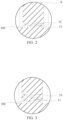
FIG. 3 is a schematic structural diagram of an annular protrusion and an annular groove provided by an embodiment of the disclosure. -
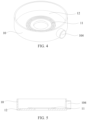
FIG. 4 is a structural schematic diagram of a support plate and part of a housing provided by an embodiment of the disclosure. -
FIG. 5 is a sectional diagram of a support plate and part of a housing provided by the embodiment illustrated inFIG. 4 . -
FIG. 6 is a sectional diagram of a pulping device provided by another embodiment of the disclosure. -
FIG. 7 is a schematic structural diagram of a guide impeller provided by an embodiment of the disclosure. -
FIG. 8 is a sectional diagram of a guide impeller provided by the embodiment ofFIG. 7 . - Reference signs:
pulping device 100;housing 10;cavity 101;clearance 102;liquid inlet 103;liquid outlet 104;second flow channel 105;third flow channel 106;feed inlet 107;annular protrusion 11;support plate 12;drive shaft 20;impeller assembly 30;first flow channel 301; opening 3011;annular groove 31; mixingimpeller 32;guide impeller 33;guide flow channel 331; andguide vane 332. - The pulping device of embodiments of the disclosure will be described in detail with reference to
FIG. 1 to FIG. 8 . Under the condition of no conflict, the following embodiments and features in the embodiments can complement each other or be combined with each other. - The disclosure provides a
pulping device 100. The pulping device includes ahousing 10, adrive shaft 20 and animpeller assembly 30. Thehousing 10 defines acavity 101, thedrive shaft 20 is disposed in thecavity 101, and theimpeller assembly 30 is disposed in thecavity 101 and is configured to be driven to rotate by thedrive shaft 20. - A bottom surface of the
impeller assembly 30 is disposed opposite to an end surface of thehousing 10, one of the bottom surface of theimpeller assembly 30 or the end surface of thehousing 10 is provided with anannular protrusion 11, the other one of the bottom surface of theimpeller assembly 30 or the end surface of thehousing 10 defines anannular groove 31 matching theannular protrusion 11, and an interference-proof clearance 102 is defined between an outer wall of theannular protrusion 11 and an inner wall of theannular groove 31. - The
annular protrusion 11 and theannular groove 31 matching theannular protrusion 11 are disposed on the bottom surface of theimpeller assembly 30 and the end surface of thehousing 10 to form a labyrinthine sealing structure, which can prevent liquid which does not participate in mixing from flowing out of a liquid outlet directly after passing through theclearance 102 due to an excessive clearance between the bottom surface of theimpeller assembly 30 and the end surface of thehousing 10. By means of theannular protrusion 11 and the matchingannular groove 31, the flow path of the liquid can be changed, so that the liquid flows to theimpeller assembly 30 as much as possible and participates in powder mixing, which is configured to improve the mixing efficiency and ensure mixing quality. - In an embodiment, as illustrated in
FIG. 1 , thehousing 10 of thepulping device 100 defines aliquid inlet 103 in a bottom side wall of thehousing 10, thehousing 10 defines aliquid outlet 104 in a middle side wall of thehousing 10, and thehousing 10 defines afeed inlet 107 on the top. Liquid enters thecavity 101 through theliquid inlet 103, powder enters thecavity 101 through thefeed inlet 107, the powder is dispersed by theimpeller assembly 30 and then is mixed with the liquid, and pulp formed after mixing flows out through theliquid outlet 104. - In an embodiment, as illustrated in
FIGS. 1 ,4, and 5 , thehousing 10 is provided with asupport plate 12, one of the bottom surface of theimpeller assembly 30 or an upper surface of thesupport plate 12 is provided with anannular protrusion 11, and the other of the bottom surface of theimpeller assembly 30 or the upper surface of thesupport plate 12 defines theannular groove 31 matching theannular protrusion 11. By disposing thesupport plate 12, thecavity 101 is divided into two parts, an upper part and a lower part, theimpeller assembly 30 is disposed in a part of thecavity 101 above thesupport plate 12, and other components can be disposed in a part of thecavity 101 below thesupport plate 12 such as a dispersion cylinder for dispersing pulp. Theliquid outlet 104 is defined above thesupport plate 12. The pulp can flow out directly through theliquid outlet 104 after being mixed by theimpeller assembly 30, which is quick and convenient. - In an embodiment, as illustrated in
FIG. 1 , thedrive shaft 20 passes through thesupport plate 12, asecond flow channel 105 is defined between thedrive shaft 20 and thesupport plate 12, and athird flow channel 106 is defined below thesupport plate 12. The liquid entering from theliquid inlet 103 can pass through thethird flow channel 106 and thesecond flow channel 105 in sequence and then enter thecavity 101 above thesupport plate 12. - In an embodiment, as illustrated in
FIG. 1 , theimpeller assembly 30 defines afirst flow channel 301, thefirst flow channel 301 extends through a bottom surface of theimpeller assembly 30 and a side surface of theimpeller assembly 30, and thefirst flow channel 301 communicates with thecavity 101. Since theannular protrusion 11 and theannular groove 31 are disposed on the bottom surface of theimpeller assembly 30 and the end surface of thehousing 10, theannular protrusion 11 and theannular groove 31 cooperatively prevent the liquid from flowing, and thus by defining thefirst flow channel 301, a passage for the liquid to flow can be provided, which facilitates the liquid to flow to the top and side of theimpeller assembly 30 to participate in mixing with the powder. - In an embodiment, as illustrated in
FIG. 1 , thefirst flow channel 301 has anopening 3011 on the bottom surface of theimpeller assembly 30, and a distance between the opening 3011 and thedrive shaft 20 is less than a radius of theannular protrusion 11. As such, after the liquid enters theclearance 102 between the bottom surface of theimpeller assembly 30 and the end surface (or the upper surface of the support plate 12) of thehousing 10, the liquid enters thefirst flow channel 301 through the opening 3011 on the bottom surface of theimpeller assembly 30, which can more effectively prevent the liquid from passing through theclearance 102 directly and flowing out of theliquid outlet 104 without participating in mixing. - In an embodiment, as illustrated in
FIG. 1 , theimpeller assembly 30 includes amixing impeller 32, one of a bottom surface of themixing impeller 32 or the end surface of thehousing 10 is provided with theannular protrusion 11, and the other one of the bottom surface of themixing impeller 32 or the end surface of thehousing 10 defines theannular groove 31 matching theannular protrusion 11. When the powder falls down from thefeed inlet 107, themixing impeller 32 is able to break up lumps in the falling powder, and after the powder is in contact with the liquid, themixing impeller 32 stirs a liquid mixture of the powder and the liquid, thereby obtaining a pulp with better mixing effect. - When the
support plate 12 is disposed in thehousing 10, one of the bottom surface of themixing impeller 32 or the upper surface of thesupport plate 12 is provided with theannular protrusion 11, and the other one of the bottom surface of themixing impeller 32 or the upper surface of thesupport plate 12 defines theannular groove 31 matching theannular protrusion 11. - In an embodiment, as illustrated in
FIG. 6 , theimpeller assembly 30 includes themixing impeller 32 and aguide impeller 33, theguide impeller 33 is disposed below themixing impeller 32, and one of a bottom surface of theguide impeller 33 or the end surface of thehousing 10 is provided with theannular protrusion 11, and the other one of the bottom surface of theguide impeller 33 or end surface of thehousing 10 defines theannular groove 31 matching theannular protrusion 11. Theguide impeller 33 is able to guide the liquid to flow above themixing impeller 32, thereby facilitating mixing of the liquid and the powder. - When the
support plate 12 is disposed in thehousing 10, one of the bottom surface of theguide impeller 33 or the upper surface of thesupport plate 12 is provided with theannular protrusion 11, and the other one of the bottom surface of theguide impeller 33 or the upper surface of the support plate defines theannular groove 31 matching theannular protrusion 11. - In an embodiment, as illustrated in
FIGS. 7 and 8 , theguide impeller 33 defines aguide flow channel 331 disposed around a central axis of theguide impeller 33, and a guide vane(s) 332 is disposed in theguide flow channel 331. The guide vane(s) 332 of theguide impeller 33 is disposed obliquely. When the guide impeller 33 rotates, theguide impeller 33 attracts the liquid below theguide impeller 33, and attracts the liquid into theguide flow channel 331 and to flow into thefirst flow channel 301. - In an embodiment, a dimension of a clearance between the outer wall of the
annular protrusion 11 and the inner wall of theannular groove 31 is in a range of 0.05 mm-0.5 mm. In this way, the clearance is small, and the liquid can be prevented from flowing out through the clearance effectively. - In an embodiment, a cross section of the
annular protrusion 11 is rectangular, triangular, semicircular, trapezoidal or irregular, and a cross section of theannular groove 31 is rectangular, triangular, semicircular, trapezoidal or irregular. For example, the cross section of theannular protrusion 11 is semicircular, the cross section of theannular groove 31 is semicircular, and the semicircularannular protrusion 11 and the semicircularannular groove 31 each have a simple structure and are easy to be manufactured. - In an embodiment, multiple
annular protrusions 11 and multipleannular grooves 31 are provided. The multiple annular protrusions are coaxial and spaced apart from one another, and the multipleannular grooves 31 correspond to the multipleannular protrusions 11, and are coaxial and spaced apart from one another. In the illustrated embodiment, in a direction from thedrive shaft 20 to a side wall of thehousing 10, radii of the multipleannular protrusions 11 sequentially increases, and radii of the multipleannular groove 31 sequentially increases. The multipleannular protrusions 11 and the multipleannular grooves 31 cooperate with each other to improve the sealing performance of theclearance 102 and reduce the flow of liquid passing through theclearance 102. - In an embodiment, cross sections of the multiple
annular protrusions 11 are in the shape of any one or any combination of rectangle, triangle, semicircle, trapezoid, or irregular shapes, and cross sections of the multiple theannular grooves 31 are in the shape of any one or any combination of rectangle, triangle, semicircle, trapezoid, or irregular shapes. Cross sections of theannular protrusion 11 and theannular groove 31 adjacent to theannular protrusion 11 may be the same in shape, for example, both rectangular. Cross sections ofannular protrusion 11 and theannular groove 31 adjacent to theannular protrusion 11 may also be different in shape, for example, the cross section of theannular protrusion 11 is rectangular, and the cross section of theannular groove 31 adjacent to theannular protrusion 11 is semi-circular. - In an embodiment, as illustrated in
FIG. 3 , in the direction from thedrive shaft 20 to a side wall of thehousing 10, radii of the multipleannular protrusions 11 successively increase, heights of the multipleannular protrusions 11 successively decrease, and depths of the multipleannular grooves 31 successively decrease correspondingly. After the liquid enters theclearance 102, the liquid firstly enters between theannular protrusion 11 with the smallest radius and theannular groove 31 with the smallest radius. Setting theannular protrusion 11 with the smallest radius higher is more conducive to preventing the liquid from entering between the outer wall of theannular protrusion 11 and the inner wall of theannular groove 31, thereby preventing the liquid from flowing through theclearance 102. - In an embodiment, in the direction from the
drive shaft 20 to a side wall of thehousing 10, radii of the multipleannular projections 11 successively increase, heights of the multipleannular projections 11 successively increase, and depths of the multipleannular grooves 31 successively increase correspondingly. After the liquid enters theclearance 102, the liquid moves in a direction from thedrive shaft 20 to the side wall of thehousing 10, andannular protrusions 11 with successively increase height are more conducive to preventing the liquid from flowing through theclearance 102. - A specific working flow of the pulping device provided in the disclosure is as follows.
- As illustrated in
FIG. 6 , liquid enters thecavity 101 of thehousing 10 through theliquid inlet 103, the liquid flows through thethird flow channel 106 and thesecond flow channel 105 in sequence, and then enters theguide flow channel 331 under the attraction force provided by theguide impeller 33. Some of the liquid enters theclearance 102, and due to the obstruction of theannular protrusion 11 and theannular groove 31, the liquid hardly flows out through theclearance 102. The liquid entering theguide flow channel 331 continues to flow upwards and enters thefirst flow channel 301, and then flows out of theimpeller assembly 30 to the top and side of the impeller assembly. The powder enters thecavity 101 through thefeed inlet 107 and then contacts with the liquid, theimpeller assembly 30 mixes and stirs the liquid and the powder to obtain pulp, and the pulp finally flows out through theliquid outlet 104. - The above are merely preferred embodiments of the disclosure, and is not a limitation to the disclosure in any form. Although the disclosure has been disclosed with the preferred embodiments as above, the above embodiments are not intended to limit the disclosure, any person skilled in the art can make some changes or modifications to equivalent embodiments without departing from the scope of the technical solutions of the disclosure, However, according to the technical essence of the disclosure, any simple modification, equivalent change, and modification made without departing from the technical solution of the disclosure to the above embodiments all belong to the scope of the technical solutions of the disclosure.
- The disclosure of this patent document contains material that is subject to copyright protection. The copyright belongs to the copyright owner. The copyright owner has no objection to reproduction by anyone of the patent document or the disclosure form the official records and archives of the Patent and Trademark Office.
Claims (15)
- A pulping device, comprising:a housing (10) defining a cavity (101);a drive shaft (20);an impeller assembly (30), disposed in the cavity (101), is configured to be driven to rotate by the drive shaft (20); whereina bottom surface of the impeller assembly (30) is disposed opposite to an end surface of the housing (10); and one of the bottom surface of the impeller assembly (30) or the end surface of the housing (10) is provided with an annular protrusion (11), the other one of the bottom surface of the impeller assembly (30) or the end surface of the housing (10) defines an annular groove (31) matching the annular protrusion (11), and an interference-proof clearance (102) is defined between an outer wall of the annular protrusion (11) and an inner wall of the annular groove (31).
- The pulping device of claim 1, wherein a dimension of the clearance between the outer wall of the annular protrusion (11) and the inner wall of the annular groove (31) is in a range of 0.05 mm-0.5 mm.
- The pulping device of claim 1, wherein a cross section of the annular protrusion (11) is rectangular, triangular, semicircular, trapezoidal, or irregular, and a cross section of the annular groove (31) is rectangular, triangular, semicircular, trapezoidal, or irregular.
- The pulping device of claim 1, wherein the annular protrusion (11) is implemented as a plurality of annular protrusions, the annular groove (31) is implemented as a plurality of annular groove (31), the plurality of annular protrusions are coaxial and spaced apart from one another, and the plurality of annular grooves (31) correspond to the plurality of annular protrusions (11) and are coaxial and spaced apart from one another.
- The pulping device of claim 4, wherein cross sections of the plurality of annular protrusions (11) are in the shape of any one or any combination of rectangle, triangle, semicircle, trapezoid, or irregular shapes, and cross sections of the plurality of the annular grooves (31) are in the shape of any one or any combination of rectangle, triangle, semicircle, trapezoid, or irregular shapes.
- The pulping device of claim 4, wherein in a direction from the drive shaft (20) to a side wall of the housing (10), radii of the plurality of annular protrusions (11) successively increase, heights of the plurality of annular protrusions (11) successively decrease, and depths of the plurality of annular grooves (31) successively decrease correspondingly.
- The pulping device of claim 4, wherein in a direction from the drive shaft (20) to a side wall of the housing (10), the radii of the plurality of annular protrusions (11) successively increase, the heights of the plurality of annular protrusions (11) successively increase, and the depths of the plurality of annular grooves (31) successively increase correspondingly.
- The pulping device of claim 1, wherein the impeller assembly (30) comprises a mixing impeller (32), one of a bottom surface of the mixing impeller (32) or the end surface of the housing (10) is provided with the annular protrusion (11), and the other one of the bottom surface of the mixing impeller (32) or the end surface of the housing (10) defines the annular groove (31) matching the annular protrusion (11).
- The pulping device of claim 8, wherein the housing (10) is provided with a support plate (12), one of the bottom surface of the mixing impeller (32) or an upper surface of the support plate (12) is provided with the annular protrusion (11), and the other one of the bottom surface of the mixing impeller (32) or the upper surface of the support plate (12) defines the annular groove (31) matching the annular protrusion (11).
- The pulping device of claim 1, wherein the impeller assembly (30) comprises a mixing impeller (32) and a guide impeller (33), the guide impeller (33) is disposed below the mixing impeller (32); one of a bottom surface of the guide impeller (33) or the end surface of the housing (10) defines the annular protrusion (11), and the other one of the bottom surface of the guide impeller (33) or the end surface of the housing (10) defines the annular groove (31) matching the annular protrusion (11).
- The pulping device of claim 10, wherein the housing (10) is provided with a support plate (12), one of the bottom surface of the guide impeller (33) or an upper surface of the support plate (12) is provided with the annular protrusion (11), and the other one of the bottom surface of the guide impeller (33) or the upper surface of the support plate (12) defines the annular groove (31) matching the annular protrusion (11).
- The pulping device of claim 10, wherein the guide impeller (33) defines a guide flow channel (331) around a central axis of the guide impeller (33), and a guide vane (332) is disposed in the guide flow channel (331).
- The pulping device of claim 1, wherein the housing (10) is provided with a support plate (12), one of the bottom surface of the impeller assembly (30) or an upper surface of the support plate (12) is provided with the annular protrusion (11), and the other one of the bottom surface of the impeller assembly (30) or the upper surface of the support plate (12) defines the annular groove (31) matching the annular protrusion (11).
- The pulping device of claim 1, wherein the impeller assembly (30) defines a first flow channel (301), the first flow channel (301) extends through the bottom surface of the impeller assembly (30) and a side surface of the impeller assembly (30), and the first flow channel (301) communicates with the cavity (101).
- The pulping device of claim 14, wherein the first flow channel (301) has an opening (3011) on the bottom surface of the impeller assembly (30), and a distance between the opening (3011) and the drive shaft (20) is less than a radius of the annular protrusion (11).
Priority Applications (1)
| Application Number | Priority Date | Filing Date | Title |
|---|---|---|---|
| MA72401A MA72401B1 (en) | 2023-04-12 | 2024-03-28 | DOUGH REDUCTION DEVICE |
Applications Claiming Priority (1)
| Application Number | Priority Date | Filing Date | Title |
|---|---|---|---|
| CN202320880077.7U CN219849006U (en) | 2023-04-12 | 2023-04-12 | Pulp making equipment |
Publications (2)
| Publication Number | Publication Date |
|---|---|
| EP4491264A1 true EP4491264A1 (en) | 2025-01-15 |
| EP4491264B1 EP4491264B1 (en) | 2026-02-04 |
Family
ID=88319984
Family Applications (1)
| Application Number | Title | Priority Date | Filing Date |
|---|---|---|---|
| EP24167663.4A Active EP4491264B1 (en) | 2023-04-12 | 2024-03-28 | Pulping device |
Country Status (6)
| Country | Link |
|---|---|
| US (1) | US20240341534A1 (en) |
| EP (1) | EP4491264B1 (en) |
| JP (1) | JP7839216B2 (en) |
| KR (1) | KR20240152235A (en) |
| CN (1) | CN219849006U (en) |
| MA (1) | MA72401B1 (en) |
Citations (7)
| Publication number | Priority date | Publication date | Assignee | Title |
|---|---|---|---|---|
| DE673014C (en) * | 1935-11-07 | 1939-03-14 | Bergedorfer Eisenwerk Akt Ges | Refiner for the production of physical foam for fire extinguishing purposes |
| GB646591A (en) * | 1948-03-03 | 1950-11-22 | Earle Thomas Oakes | Improvements relating to mixing devices |
| GB780661A (en) * | 1954-10-13 | 1957-08-07 | William Ralph Sergeant | Improvements in comminuting, mixing and like machines |
| WO2019011963A1 (en) * | 2017-07-12 | 2019-01-17 | Aflenzer Robert | METHOD AND DEVICE FOR TREATING CONTAMINATES IN THE WATER BY CAVITATION |
| CN113499698A (en) * | 2021-07-30 | 2021-10-15 | 宏工科技股份有限公司 | Powder-liquid mixer |
| US20220062852A1 (en) * | 2018-12-26 | 2022-03-03 | M. Technique Co., Ltd. | Fluid processing apparatus |
| CN218834318U (en) * | 2022-12-21 | 2023-04-11 | 浙江软控智能科技有限公司 | Lower-inlet and upper-outlet type multi-shearing dispersion machine |
Family Cites Families (5)
| Publication number | Priority date | Publication date | Assignee | Title |
|---|---|---|---|---|
| JPS62174627U (en) * | 1986-04-23 | 1987-11-06 | ||
| JPH1180602A (en) * | 1997-09-16 | 1999-03-26 | Dainippon Ink & Chem Inc | Powder slurry paint manufacturing method |
| JP5933298B2 (en) | 2011-03-23 | 2016-06-08 | 株式会社粉研パウテックス | Continuous kneader |
| EP2868369B1 (en) | 2013-11-01 | 2016-05-25 | Umicore AG & Co. KG | In-line rotor-stator disperser and method |
| JP7702725B2 (en) | 2021-08-02 | 2025-07-04 | 株式会社パウレック | In-line Dispersion Device |
-
2023
- 2023-04-12 CN CN202320880077.7U patent/CN219849006U/en active Active
- 2023-11-17 US US18/512,919 patent/US20240341534A1/en active Pending
-
2024
- 2024-03-28 MA MA72401A patent/MA72401B1/en unknown
- 2024-03-28 EP EP24167663.4A patent/EP4491264B1/en active Active
- 2024-04-09 KR KR1020240047767A patent/KR20240152235A/en active Pending
- 2024-04-09 JP JP2024062649A patent/JP7839216B2/en active Active
Patent Citations (7)
| Publication number | Priority date | Publication date | Assignee | Title |
|---|---|---|---|---|
| DE673014C (en) * | 1935-11-07 | 1939-03-14 | Bergedorfer Eisenwerk Akt Ges | Refiner for the production of physical foam for fire extinguishing purposes |
| GB646591A (en) * | 1948-03-03 | 1950-11-22 | Earle Thomas Oakes | Improvements relating to mixing devices |
| GB780661A (en) * | 1954-10-13 | 1957-08-07 | William Ralph Sergeant | Improvements in comminuting, mixing and like machines |
| WO2019011963A1 (en) * | 2017-07-12 | 2019-01-17 | Aflenzer Robert | METHOD AND DEVICE FOR TREATING CONTAMINATES IN THE WATER BY CAVITATION |
| US20220062852A1 (en) * | 2018-12-26 | 2022-03-03 | M. Technique Co., Ltd. | Fluid processing apparatus |
| CN113499698A (en) * | 2021-07-30 | 2021-10-15 | 宏工科技股份有限公司 | Powder-liquid mixer |
| CN218834318U (en) * | 2022-12-21 | 2023-04-11 | 浙江软控智能科技有限公司 | Lower-inlet and upper-outlet type multi-shearing dispersion machine |
Also Published As
| Publication number | Publication date |
|---|---|
| KR20240152235A (en) | 2024-10-21 |
| US20240341534A1 (en) | 2024-10-17 |
| JP2024152666A (en) | 2024-10-25 |
| MA72401B1 (en) | 2026-03-31 |
| CN219849006U (en) | 2023-10-20 |
| JP7839216B2 (en) | 2026-04-01 |
| EP4491264B1 (en) | 2026-02-04 |
Similar Documents
| Publication | Publication Date | Title |
|---|---|---|
| US20220379274A1 (en) | Impeller Assembly For Dispersing Solid In Liquid and Solid- Liquid Mixing Device Using Impeller Assembly | |
| EP0333111A1 (en) | Continuous two-liquid type mixer | |
| CN219186701U (en) | Double-layer liquid dispersing structure and powder-liquid mixing device | |
| EP4445997A1 (en) | Mixing impeller and pulping device | |
| US3693656A (en) | Device for adding and distributing a liquid or a gas in other media | |
| CN116236936B (en) | Pulping equipment and pulping system | |
| CN215539921U (en) | Titanium white powder and powder progressive dispersing device | |
| US20240341534A1 (en) | Pulping Device | |
| WO2024198143A1 (en) | Slurry making apparatus and slurry making system | |
| WO2022252530A1 (en) | Mixture stirring device | |
| KR101376971B1 (en) | Modular inline type homo mixer using vortex | |
| CN218307781U (en) | Dispersing device | |
| WO2024198137A1 (en) | Impeller assembly and pulping apparatus | |
| CN114699963B (en) | Stirring device and application thereof | |
| EP4674519A1 (en) | Stirring device for high solid content slurry | |
| CN222196751U (en) | A water-fertilizer mixer integrating water-dynamic vortex mixing and electric spiral mixing | |
| WO2024198142A1 (en) | Pulping apparatus and pulping system | |
| CN120169196A (en) | Carbonator and Sparkling Water Devices | |
| CN223159121U (en) | Mixing arrangement of printing ink raw materials | |
| CN221732937U (en) | A slurry dispersing device | |
| CN221619128U (en) | High-efficient solid-liquid mixing dispersion structure | |
| CN215963339U (en) | Lubricating oil circulation stirring allotment equipment | |
| CN220726597U (en) | Solid-liquid mixing centrifugal pump with spoiler | |
| CN117298955B (en) | Horizontal pulping equipment and pulping system | |
| CN219722535U (en) | Homogenization device, homogenization system and battery production line |
Legal Events
| Date | Code | Title | Description |
|---|---|---|---|
| PUAI | Public reference made under article 153(3) epc to a published international application that has entered the european phase |
Free format text: ORIGINAL CODE: 0009012 |
|
| STAA | Information on the status of an ep patent application or granted ep patent |
Free format text: STATUS: REQUEST FOR EXAMINATION WAS MADE |
|
| 17P | Request for examination filed |
Effective date: 20240328 |
|
| AK | Designated contracting states |
Kind code of ref document: A1 Designated state(s): AL AT BE BG CH CY CZ DE DK EE ES FI FR GB GR HR HU IE IS IT LI LT LU LV MC ME MK MT NL NO PL PT RO RS SE SI SK SM TR |
|
| RAV | Requested validation state of the european patent: fee paid |
Extension state: MA Effective date: 20250715 |
|
| GRAP | Despatch of communication of intention to grant a patent |
Free format text: ORIGINAL CODE: EPIDOSNIGR1 |
|
| STAA | Information on the status of an ep patent application or granted ep patent |
Free format text: STATUS: GRANT OF PATENT IS INTENDED |
|
| RIC1 | Information provided on ipc code assigned before grant |
Ipc: B01F 23/53 20220101AFI20250819BHEP Ipc: B01F 27/192 20220101ALI20250819BHEP Ipc: B01F 27/271 20220101ALI20250819BHEP Ipc: B01F 27/808 20220101ALI20250819BHEP Ipc: B01F 27/81 20220101ALI20250819BHEP Ipc: D21B 1/34 20060101ALI20250819BHEP Ipc: A47J 43/046 20060101ALI20250819BHEP Ipc: A47J 43/07 20060101ALI20250819BHEP |
|
| INTG | Intention to grant announced |
Effective date: 20250829 |
|
| GRAS | Grant fee paid |
Free format text: ORIGINAL CODE: EPIDOSNIGR3 |
|
| GRAA | (expected) grant |
Free format text: ORIGINAL CODE: 0009210 |
|
| STAA | Information on the status of an ep patent application or granted ep patent |
Free format text: STATUS: THE PATENT HAS BEEN GRANTED |
|
| AK | Designated contracting states |
Kind code of ref document: B1 Designated state(s): AL AT BE BG CH CY CZ DE DK EE ES FI FR GB GR HR HU IE IS IT LI LT LU LV MC ME MK MT NL NO PL PT RO RS SE SI SK SM TR |
|
| REG | Reference to a national code |
Ref country code: CH Ref legal event code: F10 Free format text: ST27 STATUS EVENT CODE: U-0-0-F10-F00 (AS PROVIDED BY THE NATIONAL OFFICE) Effective date: 20260204 Ref country code: GB Ref legal event code: FG4D |
|
| REG | Reference to a national code |
Ref country code: IE Ref legal event code: FG4D |
|
| REG | Reference to a national code |
Ref country code: DE Ref legal event code: R096 Ref document number: 602024002352 Country of ref document: DE |
|
| REG | Reference to a national code |
Ref country code: MA Ref legal event code: VAGR Ref document number: 72401 Country of ref document: MA Kind code of ref document: B1 |
|
| PGFP | Annual fee paid to national office [announced via postgrant information from national office to epo] |
Ref country code: DE Payment date: 20260324 Year of fee payment: 3 |
|
| PGFP | Annual fee paid to national office [announced via postgrant information from national office to epo] |
Ref country code: AT Payment date: 20260301 Year of fee payment: 3 |
|
| VSFP | Annual fee paid to validation state [announced via postgrant information from national office to epo] |
Ref country code: MA Payment date: 20260408 Year of fee payment: 3 |