EP4491078A1 - Cleaner - Google Patents
Cleaner Download PDFInfo
- Publication number
- EP4491078A1 EP4491078A1 EP23767046.8A EP23767046A EP4491078A1 EP 4491078 A1 EP4491078 A1 EP 4491078A1 EP 23767046 A EP23767046 A EP 23767046A EP 4491078 A1 EP4491078 A1 EP 4491078A1
- Authority
- EP
- European Patent Office
- Prior art keywords
- agitator
- bearing
- coupled
- cleaner
- housing
- Prior art date
- Legal status (The legal status is an assumption and is not a legal conclusion. Google has not performed a legal analysis and makes no representation as to the accuracy of the status listed.)
- Pending
Links
Images





Classifications
-
- A—HUMAN NECESSITIES
- A47—FURNITURE; DOMESTIC ARTICLES OR APPLIANCES; COFFEE MILLS; SPICE MILLS; SUCTION CLEANERS IN GENERAL
- A47L—DOMESTIC WASHING OR CLEANING; SUCTION CLEANERS IN GENERAL
- A47L5/00—Structural features of suction cleaners
- A47L5/12—Structural features of suction cleaners with power-driven air-pumps or air-compressors, e.g. driven by motor vehicle engine vacuum
- A47L5/22—Structural features of suction cleaners with power-driven air-pumps or air-compressors, e.g. driven by motor vehicle engine vacuum with rotary fans
- A47L5/24—Hand-supported suction cleaners
- A47L5/26—Hand-supported suction cleaners with driven dust-loosening tools
-
- A—HUMAN NECESSITIES
- A47—FURNITURE; DOMESTIC ARTICLES OR APPLIANCES; COFFEE MILLS; SPICE MILLS; SUCTION CLEANERS IN GENERAL
- A47L—DOMESTIC WASHING OR CLEANING; SUCTION CLEANERS IN GENERAL
- A47L9/00—Details or accessories of suction cleaners, e.g. mechanical means for controlling the suction or for effecting pulsating action; Storing devices specially adapted to suction cleaners or parts thereof; Carrying-vehicles specially adapted for suction cleaners
- A47L9/02—Nozzles
- A47L9/04—Nozzles with driven brushes or agitators
-
- A—HUMAN NECESSITIES
- A47—FURNITURE; DOMESTIC ARTICLES OR APPLIANCES; COFFEE MILLS; SPICE MILLS; SUCTION CLEANERS IN GENERAL
- A47L—DOMESTIC WASHING OR CLEANING; SUCTION CLEANERS IN GENERAL
- A47L9/00—Details or accessories of suction cleaners, e.g. mechanical means for controlling the suction or for effecting pulsating action; Storing devices specially adapted to suction cleaners or parts thereof; Carrying-vehicles specially adapted for suction cleaners
- A47L9/02—Nozzles
- A47L9/04—Nozzles with driven brushes or agitators
- A47L9/0405—Driving means for the brushes or agitators
- A47L9/0411—Driving means for the brushes or agitators driven by electric motor
-
- A—HUMAN NECESSITIES
- A47—FURNITURE; DOMESTIC ARTICLES OR APPLIANCES; COFFEE MILLS; SPICE MILLS; SUCTION CLEANERS IN GENERAL
- A47L—DOMESTIC WASHING OR CLEANING; SUCTION CLEANERS IN GENERAL
- A47L9/00—Details or accessories of suction cleaners, e.g. mechanical means for controlling the suction or for effecting pulsating action; Storing devices specially adapted to suction cleaners or parts thereof; Carrying-vehicles specially adapted for suction cleaners
- A47L9/02—Nozzles
- A47L9/04—Nozzles with driven brushes or agitators
- A47L9/0427—Gearing or transmission means therefor
-
- A—HUMAN NECESSITIES
- A47—FURNITURE; DOMESTIC ARTICLES OR APPLIANCES; COFFEE MILLS; SPICE MILLS; SUCTION CLEANERS IN GENERAL
- A47L—DOMESTIC WASHING OR CLEANING; SUCTION CLEANERS IN GENERAL
- A47L9/00—Details or accessories of suction cleaners, e.g. mechanical means for controlling the suction or for effecting pulsating action; Storing devices specially adapted to suction cleaners or parts thereof; Carrying-vehicles specially adapted for suction cleaners
- A47L9/02—Nozzles
- A47L9/04—Nozzles with driven brushes or agitators
- A47L9/0455—Bearing means therefor
-
- A—HUMAN NECESSITIES
- A47—FURNITURE; DOMESTIC ARTICLES OR APPLIANCES; COFFEE MILLS; SPICE MILLS; SUCTION CLEANERS IN GENERAL
- A47L—DOMESTIC WASHING OR CLEANING; SUCTION CLEANERS IN GENERAL
- A47L9/00—Details or accessories of suction cleaners, e.g. mechanical means for controlling the suction or for effecting pulsating action; Storing devices specially adapted to suction cleaners or parts thereof; Carrying-vehicles specially adapted for suction cleaners
- A47L9/02—Nozzles
- A47L9/04—Nozzles with driven brushes or agitators
- A47L9/0461—Dust-loosening tools, e.g. agitators, brushes
- A47L9/0466—Rotating tools
- A47L9/0477—Rolls
Definitions
- the present disclosure relates to a cleaner, and more particularly, to a vacuum cleaner capable of being easily manipulated.
- a cleaner refers to an electrical appliance that draws in small garbage or dust by sucking air using electricity and fills a dust bin provided in a product with the garbage or dust.
- a vacuum cleaner Such a cleaner is generally called a vacuum cleaner.
- the cleaners may be classified into a manual cleaner which is moved directly by a user to perform a cleaning operation, and an automatic cleaner which performs a cleaning operation while autonomously traveling.
- the manual cleaners may be classified into a canister cleaner, an upright cleaner, a handy cleaner, a stick cleaner, and the like.
- the canister cleaners were widely used in the past as household cleaners. However, recently, there is an increasing tendency to use the handy cleaner and the stick cleaner in which a dust bin and a cleaner main body are integrally provided to improve convenience of use.
- the canister cleaner In the case of the canister cleaner, a main body and a suction port are connected by a rubber hose or pipe, and in some instances, the canister cleaner may be used in a state in which a brush is fitted into the suction port.
- the handy cleaner (hand vacuum cleaner) has maximized portability and is light in weight.
- the handy cleaner has a short length, there may be a limitation to a cleaning region. Therefore, the handy cleaner is used to clean a local place such as a desk, a sofa, or an interior of a vehicle.
- a user may use the handy cleaner while standing and thus may perform a cleaning operation without bending his/her waist. Therefore, the stick cleaner is advantageous for the user to clean a wide region while moving in the region.
- Korean Patent Application Laid-Open No. 10-2020-0117361 is provided as a patent document.
- the patent document relates to a cleaner and a method of manufacturing a brush drum of the cleaner.
- the patent document includes a main body, a brush head connected to the main body and having a suction inlet, and a brush drum rotatably mounted on the brush head.
- the brush drum includes a shaft unit rotatably mounted on the brush head, a cylindrical elastic member provided to surround an outer peripheral surface of the shaft unit, a brush provided in a cylindrical shape to surround an outer peripheral surface of the elastic member and having bristles, a pair of brackets assembled at two opposite ends of the shaft unit and configured to allow the shaft unit to be rotatably mounted on the brush head, and a handle unit separably mounted on the brush head and configured such that one of the pair of brackets is separably mounted on the handle unit.
- a user may separate the handle unit, separate the bracket, separate the shaft unit, and then remove hairs and the like tangled around an outer peripheral surface of the shaft unit.
- a shaft and a pipe of the shaft unit according to the patent document are difficult to separate, which causes a problem in that it is difficult to wash the shaft unit with water because water may penetrate into a space between the shaft and the pipe during a water washing process.
- the handle unit is separably mounted on a second bracket and configured to be separated separately from the second bracket and the shaft unit. For this reason, the user is inconvenienced because the user needs to separate the handle unit and then separate the second bracket and the shaft unit.
- Patent Document 1 Korean Patent Application Laid-Open No. 10-2020-0117361
- An object to be achieved by the present disclosure is to provide a cleaner, in which a component of an assembly, such as a rag, which may be washed with water, may be separated from a component, which cannot be washed with water, and the component, which may be washed with water, may be easily washed with water.
- Another object to be achieved by the present disclosure is to provide a cleaner, in which an agitator inserted and installed into a housing may be separated by a single manipulation.
- a cleaner includes: a cleaning module configured to suck outside air; and a main body configured to provide a suction force to the cleaning module.
- the cleaning module may include: a housing coupled to the main body and having one side including an opening portion configured to allow an external space and an internal space to communicate with each other; an agitator inserted into the opening portion and rotatably coupled to the housing; an end cap configured to cover the opening portion and separably coupled to the housing; a first shaft coupled to the end cap and extending toward the inside of the agitator along a rotary shaft of the agitator; and a first bearing disposed at least partially inside the agitator and coupled to the first shaft.
- the end cap may be coupled to or separated from the housing together with the first shaft and the first bearing.
- the cleaning module may include a bearing holder disposed radially outward of the first bearing and having one side coupled to the first bearing, and the other side coupled to the agitator, the bearing holder being configured to rotate together with the agitator.
- the bearing holder may surround at least a part of an outer peripheral surface of the first bearing.
- the cleaning module may include a gasket having an inner surface tightly attached to the bearing holder, and an outer surface tightly attached to the agitator.
- the cleaning module may include a holder cover disposed radially outward of the bearing holder, configured to surround at least a part of the bearing holder, and having one side coupled to the bearing holder, and the other side coupled to the agitator.
- the holder cover may include a stepped portion formed on an inner peripheral surface thereof and tightly attached to an end of the bearing holder.
- the bearing holder may include a bearing holder coupling hook protruding from an outer peripheral surface toward the holder cover, and the holder cover may include a bearing holder coupling hole into which at least a part of the bearing holder coupling hook is inserted and caught.
- the agitator may include an agitator guide coupling protrusion protruding toward the holder cover, and the holder cover may include an agitator guide coupling groove into which at least a part of the agitator guide coupling protrusion is inserted and caught.
- the agitator may include: an agitator bar having therein a space and extending along the rotary shaft; and an agitator guide disposed on the rotary shaft and coupled to an end of the agitator bar.
- the agitator guide may include a left agitator guide having one side coupled to a left end of the agitator, and the other side coupled to the first bearing.
- the agitator guide may include a right agitator guide coupled to a right end of the agitator.
- the cleaning module may include a pulley disposed in the housing, at least partially inserted into the right agitator guide, and configured to transmit power to the right agitator guide.
- a cleaner includes: a cleaning module configured to suck outside air; and a main body configured to provide a suction force to the cleaning module.
- the cleaning module may include: a housing coupled to the main body and having one side including an opening portion configured to allow an external space and an internal space to communicate with each other; an agitator inserted into the opening portion and rotatably coupled to the housing; and an end cap assembly configured to cover at least a part of the opening portion, separably coupled to the housing, and configured to be separated together with the agitator when separated from the housing.
- the end cap assembly may be at least partially inserted into the agitator and support an inner peripheral surface of the agitator.
- the end cap assembly may include a first bearing disposed inside the agitator.
- the end cap assembly may include: an end cap configured to cover the opening portion and separably coupled to the housing; a first shaft coupled to the end cap and extending toward the inside of the agitator along a rotary shaft of the agitator; a first bearing at least partially disposed inside the agitator and coupled to the first shaft; a bearing holder configured to surround at least a part of the first bearing; and a holder cover configured to surround at least a part of the bearing holder and having one side coupled to the bearing holder, and the other side coupled to the agitator.
- a coupling force between the holder cover and the bearing holder may be higher than a coupling force between the holder cover and the agitator.
- the cleaner of the present invention has one or more of the following effects.
- the end cap may be integrally coupled to or separated from the housing together with the first shaft and the first bearing, and the agitator, which may be washed with water, may be easily separated from the first shaft or the first bearing, which cannot be washed with water, such that the agitator may be easily washed with water.
- the components of the cleaning module are classified into two assemblies including the agitator and the end cap assembly, and the end cap assembly is separated from the agitator when the end cap assembly is separated from the housing, such that the end cap assembly and the agitator may be easily separated only by the single operation.
- FIG. 1 is a perspective view of a cleaning module of a cleaner according to the present disclosure
- FIG. 2 is a front view of the cleaning module according to the present disclosure
- FIG. 3 is a top plan view of the cleaning module according to the present disclosure
- FIG. 4 is a cross-sectional view taken along line 4-4 in FIG. 3
- FIG. 5 is a cross-sectional view taken along line 5-5 in FIG. 3
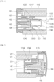
- FIG. 6 is an enlarged view of a left agitator part in FIG. 5
- FIG. 7 is an enlarged view of a right agitator part in FIG. 5
- FIGS. 8 to 10 are views illustrating a process of disassembling the cleaning module according to the present disclosure
- FIG. 11 is an exploded view of an agitator according to the present disclosure
- FIG. 12 is an exploded view of an end cap assembly according to the present disclosure.
- FIG. 1 is a perspective view of a cleaning module according to the present disclosure.
- the cleaner includes a main body (not illustrated), a cleaning module 100, and an extension tube (not illustrated).
- the main body (not illustrated) includes key constituent elements for operating the cleaner.
- the main body provides a suction force to the cleaning module 100.
- the main body includes a suction part (not illustrated) into which dust-containing air may be sucked.
- the suction part defines a flow path as the cleaning module 100 or the extension tube is connected to the suction part.
- the main body includes a suction motor (not illustrated).
- the suction motor is configured to generate a flow of air so that the dust-containing air may be introduced into the suction part.
- the main body includes a handle (not illustrated).
- the handle is a constituent element gripped by a user to move the cleaner.
- the main body includes an operating part (not illustrated).
- the operating part is a constituent element that the user uses to input an instruction to the cleaner.
- the main body includes a dust bin (not illustrated).
- the dust bin is a constituent element configured to store dust separated from air.
- the main body includes a battery (not illustrated).
- the battery is a constituent element configured to supply power to the main body or the cleaning module 100.
- the cleaning module 100 is a constituent element configured to suck outside air.
- the cleaning module 100 may be coupled indirectly to the main body through the extension tube and coupled directly to the main body.
- the extension tube (not illustrated) is a constituent element configured to connect the cleaning module 100 and the main body.
- a front end of the extension tube is coupled to the cleaning module 100 and connected to the cleaning module 100.
- a rear end of the extension tube is connected to the suction part of the main body.
- a downward direction is a front side of the cleaning module 100.
- an upward direction is a rear side of the cleaning module 100.
- a leftward direction is a left side of the cleaning module 100.
- a rightward direction is a right side of the cleaning module 100.
- an upward direction is an upper side of the cleaning module 100.
- a downward direction is a lower side of the cleaning module 100.
- a configuration of the cleaning module 100 will be described with reference to FIGS. 1 to 4 .
- the cleaning module 100 includes a housing 110.
- the housing 110 is a constituent element configured to define an external shape of the cleaning module 100.
- the housing 110 defines an external shape of the cleaning module 100 and has therein a space in which other constituent elements may be disposed.
- the housing 110 is coupled to the main body, and one side of the housing 110 includes an opening portion 112 configured to allow an external space and an internal space to communicate with each other.
- the housing 110 is coupled to the main body (not illustrated). With reference to FIG. 1 , a rear end of the housing 110 is coupled directly to the main body or coupled indirectly to the main body through the extension tube.
- One side of the housing 110 includes the opening portion 112 configured to allow the external space and the internal space to communicate with each other.
- the opening portion 112 is formed in a left surface of the housing 110. Unlike the configuration illustrated in FIG. 1 , the opening portion 112 may be formed in a right surface of the housing 110.
- the cleaning module 100 includes a suction inlet 111.
- the suction inlet 111 is a hole into which air and dust are sucked.
- the suction inlet 111 is formed in a lower surface of the housing 110.
- the suction inlet 111 may be formed rearward of an agitator 120.
- the suction inlet 111 communicates with the extension tube (not illustrated), and dust flows to the main body (not illustrated). More specifically, the suction inlet 111 is connected to one side of a corrugated pipe 160, and the other side of the corrugated pipe 160 is connected to the extension tube (not illustrated).
- the cleaning module 100 includes the agitator 120.
- the agitator 120 is a constituent element configured to wipe dust attached to a floor and separate the dust from the floor.
- the agitator 120 is inserted into the opening portion 112 of the housing 110 and rotatably coupled to the housing 110.
- the agitator 120 is formed in a cylindrical shape based on a rotary shaft.
- the rotary shaft of the agitator 120 is disposed in the leftward/rightward direction.
- a hollow portion may be formed in the agitator 120.
- the hollow portion extends along the rotary shaft.
- Agitator guides 123 and 124 may be inserted into the hollow portion.
- the agitator 120 is disposed forward of the suction inlet 111.
- the agitator 120 is disposed forward of the suction inlet 111 and wipes out the dust attached to the floor.
- the dust attached to the floor may be separated from the floor by the agitator 120 and more easily sucked into the suction inlet 111.
- the agitator 120 is rotatably coupled to the housing 110. With reference to FIG. 4 , the agitator 120 rotates counterclockwise. Alternatively, the agitator 120 may rotate clockwise based on FIG. 4 .
- the cleaning module 100 may further include a motor (not illustrated) configured to rotate the agitator 120.
- the motor may be disposed at the right side in the internal space of the cleaning module 100.
- the agitator 120 is inserted into the opening portion 112 of the housing 110. With reference to FIGS. 8 to 10 , the agitator 120 is inserted into the opening portion 112 by being moved from the left side to the right side of the housing 110. On the contrary, the agitator 120 is separated from the opening portion 112 by being moved to the left side.
- the agitator 120 may include an agitator bar 121, a rag 122, and the agitator guides 123 and 124.
- the agitator 120 includes the agitator bar 121.
- the agitator bar 121 is a constituent element configured to support the rag 122 so that the rag 122 rubs a cleaning region while having a predetermined shape.
- the agitator bar 121 has therein a space and extends along the rotary shaft.
- the agitator bar 121 is formed in a cylindrical shape. With reference to FIGS. 1 and 8 to 10, the agitator bar 121 may be formed in a cylindrical shape opened at left and right sides thereof, and the rotary shaft is disposed in the leftward/rightward direction.
- the agitator bar 121 may be made of a hard material.
- the agitator bar 121 may be made of a resin material.
- the rag 122 is a constituent element configured to clean the cleaning region while rubbing the cleaning region or separate the attached dust from the floor.
- the rag 122 may be made of a woven fabric material.
- the rag 122 is disposed outward in a radial direction of the agitator bar 121.
- the rag 122 surrounds an outer peripheral surface of the agitator bar 121.
- a shape of the rag 122 is determined by the agitator bar 121. That is, because the agitator bar 121 is formed in a cylindrical shape, the rag 122 may also be formed in a cylindrical shape.
- the agitator 120 includes the agitator guides 123 and 124.
- the agitator guides 123 and 124 are constituent elements configured to couple the agitator bar 121 to an end cap assembly 130 or the housing 110.
- the agitator guides 123 and 124 are disposed at left and right ends of the agitator bar 121.
- the agitator guides 123 and 124 may be divided into a left agitator guide 123 and a right agitator guide 124 depending on coupling positions.
- the agitator guides 123 and 124 may be arbitrarily divided into a first agitator guide and a second agitator guide.
- the first agitator guide may refer to the left agitator guide 123
- the second agitator guide may refer to the right agitator guide 124.
- the left agitator guide 123 is a constituent element configured to couple the agitator 120 to the end cap assembly 130.
- One side of the left agitator guide 123 is coupled to a left end of the agitator bar 121, and the other side of the left agitator guide 123 is coupled to a first bearing 133.
- the left agitator guide 123 is inserted into the agitator bar 121 through the opened left side of the agitator bar 121.
- the left agitator guide 123 covers the opened left surface of the agitator bar 121.
- the left agitator guide 123 and the agitator bar 121 may be fixed by coupling hooks 1237 and coupling holes 1217.
- the left agitator guide coupling hook 1237 is formed on an outer peripheral surface of the left agitator guide 123.
- the left agitator guide coupling hook 1237 protrudes toward the agitator 120.
- the left agitator guide coupling hook 1237 is formed in a wedge shape in which an outer end further protrudes than an inner end in a longitudinal direction. Therefore, a coupling force between the left agitator guide coupling hook 1237 and the left agitator guide coupling hole 1217 is higher than a coupling force between an agitator guide coupling protrusion and an agitator guide coupling groove 1355. Therefore, when the end cap assembly 130 is separated, the agitator bar 121 may also be simultaneously separated together with the left agitator guide 123.
- the left agitator guide coupling hole 1217 is formed in an inner peripheral surface of the agitator 120.
- the left agitator guide coupling hole 1217 is a hole formed through the agitator bar 121.
- the left agitator guide coupling hole 1217 may be a groove instead of a hole.
- the left agitator guide coupling hook 1237 and the left agitator guide coupling hole 1217 may be provided as a plurality of left agitator guide coupling hooks 1237 and a plurality of left agitator guide coupling holes 1217 formed in a circumferential direction.
- An agitator guide coupling protrusion 1235 may be formed at one side of the left agitator guide 123 and coupled to a holder cover 135.
- the right agitator guide 124 is a constituent element configured to couple the agitator 120 to the housing 110.
- One side of the right agitator guide 124 is coupled to a right end of the agitator bar 121, and the other side of the right agitator guide 124 is coupled to a pulley 144.
- the right agitator guide 124 is inserted into the agitator bar 121 through the opened right side of the agitator bar 121.
- the right agitator guide 124 covers the opened right side of the agitator bar 121.
- the right agitator guide 124 and the agitator bar 121 may be fixed by coupling hooks 1248 and coupling holes 1218.
- the right agitator guide coupling hook 1248 is formed on an outer peripheral surface of the right agitator guide 124.
- the right agitator guide coupling hook 1248 protrudes toward the agitator 120.
- the right agitator guide coupling hook 1248 is formed in a wedge shape in which an outer end further protrudes than an inner end. Therefore, a coupling force between the right agitator guide coupling hook 1248 and the right agitator guide coupling hole 1218 is higher than a coupling force between the agitator guide coupling protrusion 1235 and the agitator guide coupling groove 1355. Therefore, when the end cap assembly 130 is separated, the right agitator guide 124 may also be simultaneously separated together with the agitator bar 121.
- the right agitator guide coupling hole 1218 is formed in an inner peripheral surface of the agitator 120.
- the right agitator guide coupling hole 1218 is a hole formed through the agitator bar 121.
- the right agitator guide coupling hole 1218 may be a groove instead of a hole.
- the right agitator guide coupling hook 1248 and the right agitator guide coupling hole 1218 may be provided as a plurality of right agitator guide coupling hooks 1248 and a plurality of right agitator guide coupling holes 1218 formed in the circumferential direction.
- the cleaning module 100 includes the end cap assembly 130.
- the end cap assembly 130 is a constituent element configured to cover the opening portion 112 of the housing 110, block the agitator 120, and support one side of the agitator 120.
- the end cap assembly 130 covers at least a part of the opening portion 112 and is separably coupled to the housing 110. When the end cap assembly 130 may be separated from the housing 110 together with the agitator 120.
- the end cap assembly 130 is separated from the housing 110 together with the agitator 120.
- the end cap assembly 130 is separated leftward from the housing 110 together with the agitator 120. Therefore, in the related art, there is an inconvenience of having to perform at least two steps including a step of separating the end cap assembly 130 and a step of separating the agitator 120.
- the agitator 120 of the present disclosure is separated together with the end cap assembly only by a single step, such that the cleaning module 100 may be easily disassembled.
- At least a part of the end cap assembly 130 is inserted into the agitator 120 and supports the inner peripheral surface of the agitator 120.
- a portion of the end cap assembly 130, which is inserted into the agitator 120 is tightly attached to the inner peripheral surface of the agitator 120.
- a shaft protrudes in the longitudinal direction of the agitator 120, and an end cap 131 supports the shaft.
- a distance between a support point of the left end of the agitator 120 and a support point of the right end of the agitator 120 is long, and high bending stress is applied to a center of the agitator 120.
- a distance between the support point of the left end of the agitator 120 and the support point of the right end of the agitator 120 is short, and low bending stress is applied to the center of the agitator 120.
- the end cap assembly 130 may include the end cap 131, a first shaft 132, the first bearing 133, a bearing holder 134, the holder cover 135, a fixing ring 136, and a gasket 137.
- the end cap assembly 130 covers the opening portion 112 of the housing 110 and is separably coupled to the housing 110.
- the end cap 131 is coupled to or separated from the housing 110 together with the first shaft 132 and the first bearing 133.
- the end cap 131, the first shaft 132, the first bearing 133, the bearing holder 134, the holder cover 135, the fixing ring 136, and the gasket 137 constitute a single assembly and are integrally coupled to the housing 110 or integrally separated from the housing 110.
- the end cap 131 is a constituent element configured to cover the opening portion 112 and block the agitator 120.
- the end cap 131 covers the opening portion 112 of the housing 110 and separably coupled to the housing 110.
- the end cap 131 is coupled to or separated from the housing 110 together with the first shaft 132 and the first bearing 133.
- the first shaft 132 is a constituent element configured to support the agitator 120 and allow the agitator 120 to rotate about the rotary shaft.
- the first shaft 132 is coupled to the end cap 131 and extends toward the inside of the agitator 120 along the rotary shaft of the agitator 120. With reference to FIG. 6 as an example, the first shaft 132 extends toward the inside of the agitator 120 through the right side of the agitator 120.
- the first shaft 132 is coupled to the end cap 131. Specifically, the first shaft 132 may be fixed to the end cap 131 so that the first shaft 132 cannot rotate.
- the first shaft 132 may be disposed on the rotary shaft of the agitator 120. Therefore, the first shaft 132 is a rotation center when the agitator 120 rotates.
- the first bearing 133 is a constituent element configured to reduce a frictional force between the agitator 120 and the end cap 131.
- At least a part of the first bearing 133 is disposed inside the agitator 120 and coupled to the first shaft 132.
- the first bearing 133 is disposed inside the agitator 120. Therefore, a length of the cleaning module 100 in the leftward/rightward direction and designed to be shorter than that in the related art.
- the first bearing 133 is coupled to the first shaft 132. Specifically, an inner peripheral surface of the first bearing 133 is tightly attached to an outer peripheral surface of the first shaft 132.
- the first bearing 133 may be a radial bearing. That is, the first bearing 133 supports a load applied from the agitator 120 in a direction perpendicular to the rotary shaft.
- the first shaft 132 includes a flange tightly attached to the outer end of the first bearing 133 and protruding radially outward.
- the fixing ring 136 is installed at an inner end of the first bearing 133.
- the first bearing 133 is coupled to the first shaft 132 by the flange and the fixing ring 136.
- the cleaning module 100 includes the bearing holder 134.
- the bearing holder 134 is a constituent element configured to surround the first bearing 133 and transmit a load of the agitator 120 to the bearing.
- the bearing holder 134 is disposed radially outward of the first bearing 133 and has one side coupled to the first bearing 133, and the other side coupled to the agitator 120, such that the bearing holder 134 rotates together with the agitator 120.
- the bearing holder 134 may be formed in a cylindrical shape opened at left and right sides thereof.
- the bearing holder 134 is disposed radially outward of the first shaft 132 and coupled to the end cap 131.
- the bearing holder 134 surrounds at least a part of the outer peripheral surface of the first bearing 133. At least a part of the inner peripheral surface of the bearing holder 134 is tightly attached to the outer peripheral surface of the first bearing 133. With this arrangement, the bearing holder 134 may be stably coupled to the first bearing 133 and/or the end cap 131 even without a separate coupling element.
- the bearing holder 134 may include a flange tightly attached to the outer end of the first bearing 133 protruding radially inward.
- the flange may be opposite to the flange of the first shaft 132.
- the bearing holder 134 includes a bearing holder coupling hook 1343 to be coupled to the holder cover 135.
- the cleaning module 100 includes the holder cover 135.
- the holder cover 135 is a constituent element configured to surround the bearing holder 134 and fix the agitator 120 and the end cap assembly 130.
- the holder cover 135 is disposed radially outward of the bearing holder 134 and surrounds at least a part of the bearing holder 134.
- the holder cover 135 has one side coupled to the bearing holder 134, and the other side coupled to the agitator 120.
- the holder cover 135 may be formed in a cylindrical shape opened at left and right sides thereof.
- the holder cover 135 is disposed radially outward of the bearing holder 134 and coupled to the bearing holder 134.
- the holder cover 135 may further protrude inward in the longitudinal direction of the bearing holder 134.
- the holder cover 135 includes a stepped portion 1351.
- the stepped portion 1351 is a constituent element configured to support the bearing holder 134.
- the stepped portion 1351 is formed on an inner peripheral surface of the holder cover 135 and tightly attached to an end of the bearing holder 134.
- the stepped portion 1351 may extend circumferentially and formed in a ring shape.
- An inner end of the bearing holder 134 in the longitudinal direction is tightly attached to the stepped portion 1351, such that the bearing holder 134 may be coupled to the holder cover 135.
- the stepped portion 1351 may be disposed inward of the first bearing 133 in the longitudinal direction.
- the bearing holder 134 and the holder cover 135 are fixed by coupling hooks 1343 and coupling holes 1353.
- the bearing holder coupling hook 1343 protrudes from the outer peripheral surface of the bearing holder 134 toward the holder cover 135.
- the bearing holder coupling hook 1343 is formed on the outer peripheral surface of the bearing holder 134.
- the bearing holder coupling hook 1343 protrudes toward the holder cover 135. In other words, the bearing holder coupling hook 1343 protrudes radially outward.
- the bearing holder coupling hook 1343 is formed in a wedge shape in which an outer end further protrudes than an inner end in the longitudinal direction. Therefore, a coupling force between the bearing holder coupling hook 1343 and the bearing holder coupling hole 1353 is higher than a coupling force between the agitator guide coupling protrusion 1235 and the agitator guide coupling groove 1355. Therefore, when the end cap assembly 130 is separated, the holder cover 135 may be separated together with the bearing holder 134.
- the bearing holder coupling hole 1353 is formed in the holder cover 135, and at least a part of the bearing holder coupling hook 1343 is inserted into and caught by the bearing holder coupling hole 1353.
- the bearing holder coupling hole 1353 is a hole radially formed through the holder cover 135.
- the bearing holder coupling hole 1353 may be a groove instead of a hole.
- the bearing holder coupling hook 1343 and the bearing holder coupling hole 1353 may be provided as a plurality of bearing holder coupling hooks 1343 and a plurality of bearing holder coupling holes 1353 in the circumferential direction.
- the holder cover 135 may be coupled to the bearing holder 134 and rotate together with the bearing holder 134.
- the agitator 120 and the holder cover 135 are fixed by the coupling protrusion 1235 and the coupling groove 1355.
- the agitator guide coupling protrusion 1235 is formed on the agitator 120 and protrudes toward the holder cover 135.
- the agitator guide coupling protrusion 1235 is formed on the inner peripheral surface of the left agitator guide 123.
- the agitator guide coupling protrusion 1235 protrudes toward the holder cover 135. In other words, the agitator guide coupling protrusion 1235 protrudes radially inward.
- the agitator guide coupling protrusion 1235 is formed in a protrusion shape in which an inclination of an outer end and an inclination of an inner end in the longitudinal direction are identical to each other. Therefore, a coupling force between the agitator guide coupling protrusion 1235 and the agitator guide coupling groove 1355 is lower than the coupling force between the left agitator guide coupling hook 1237 and the left agitator guide coupling hole 1217 and lower than the coupling force between the bearing holder coupling hook 1343 and the bearing holder coupling hole 1353.
- the agitator guide coupling protrusion 1235 and the agitator guide coupling groove 1355 are unfixed, such that the agitator guide coupling protrusion 1235 and the agitator guide coupling groove 1355 may be separated.
- the agitator guide coupling groove 1355 is formed in the holder cover 135, and at least a part of the agitator guide coupling protrusion 1235 is inserted into and caught by the agitator guide coupling groove 1355.
- the agitator guide coupling groove 1355 is recessed radially inward from the outer peripheral surface of the holder cover 135.
- the agitator guide coupling groove 1355 is a groove recessed radially inward. However, unlike the configuration illustrated in FIG. 6 , the agitator guide coupling groove 1355 may be a hole instead of a groove.
- the agitator guide coupling protrusion 1235 and the agitator guide coupling groove 1355 may be provided as a plurality of agitator guide coupling protrusions 1235 and a plurality of agitator guide coupling grooves 1355 in the circumferential direction.
- the holder cover 135 may be coupled to the left agitator guide 123 and rotate together with the left agitator guide 123. Specifically, the bearing holder 134, the holder cover 135, the left agitator guide 123, the agitator bar 121, and the rag 122 rotate simultaneously.
- the agitator guide coupling groove 1355 may be disposed longitudinally inward of the bearing holder coupling hole 1353.
- a coupling force between the holder cover 135 and the bearing holder 134 is higher than a coupling force between the holder cover 135 and the agitator 120.
- the coupling force between the holder cover 135 and the bearing holder 134 is generated by the bearing holder coupling hook 1343 with a wedge shape.
- the coupling force between the holder cover 135 and the agitator 120 is generated by the agitator guide coupling protrusion 1235 with a gradual protrusion shape. Therefore, the coupling force between the holder cover 135 and the bearing holder 134 is higher than the coupling force between the holder cover 135 and the agitator 120.
- the holder cover 135 is disposed on the end cap assembly 130 instead of being disposed on the agitator 120. Therefore, the first bearing 133 may be prevented from being exposed, and a lifespan of the first bearing 133 may be improved.
- the fixing ring 136 is a constituent element configured to fix the first bearing 133 to the first shaft 132.
- the fixing ring 136 is tightly attached to the inner end of the first bearing 133 based on the longitudinal direction and prevents the first bearing 133 from being withdrawn from the first shaft 132.
- the fixing ring 136 may be an E-ring.
- the fixing ring 136 is installed on the outer peripheral surface of the first shaft 132.
- the cleaning module 100 includes the gasket 137.
- the gasket 137 is a constituent element that fills a gap between the agitator 120 and the bearing holder 134.
- An inner surface of the gasket 137 is tightly attached to the bearing holder 134, and an outer surface of the gasket 137 is tightly attached to the agitator 120. Specifically, the inner surface of the gasket 137 is tightly attached to the outer peripheral surface of the bearing holder 134, and the outer surface of the gasket 137 is tightly attached to the inner peripheral surface of the left agitator guide 123.
- the gasket 137 may include a first portion and a second portion.
- the first portion is tightly attached to the bearing holder 134 and extends outward in the longitudinal direction.
- the second portion extends outward in the longitudinal direction from an inner end of the first portion based on the longitudinal direction.
- the inner end of the first portion and an inner end of the second portion are connected to each other, and an outer end of the first portion and an outer end of the second portion are spaced apart from each other.
- the gasket 137 is formed in a V-shape opened at a longitudinal outer side thereof.
- the gasket 137 is disposed longitudinally outward of the holder cover 135. With reference to FIG. 6 as an example, the gasket 137 is disposed at the left side of the holder cover 135.
- the gasket 137 fills a gap between the agitator 120 and the bearing holder 134, thereby ensuring a dust suction force in the cleaning module 100.
- the drive part is a constituent element configured to generate power for operating the agitator 120 and supply the power to the agitator 120.
- the drive part includes the motor (not illustrated), a second shaft 142, a second bearing 143, the pulley 144, and a belt 145.
- the motor (not illustrated) is a constituent element configured to generate power for operating the agitator 120.
- the motor generates power by receiving electric power from a battery disposed in the main body.
- the motor may be disposed at the right side in the internal space of the cleaning module 100.
- the cleaning module 100 includes the second shaft 142.
- the second shaft 142 is a constituent element configured to support the agitator 120 and allow the agitator 120 to rotate about the rotary shaft.
- the second shaft 142 is disposed in the housing 110 and extends toward the inside of the agitator 120 along the rotary shaft of the agitator 120. With reference to FIG. 7 as an example, the second shaft 142 extends toward the inside of the agitator 120 through the right side of the agitator 120.
- the second shaft 142 is coupled to the housing 110. Specifically, the second shaft 142 may be fixed to the housing 110 so that the second shaft 142 cannot rotate.
- the second shaft 142 may be disposed on the rotary shaft of the agitator 120. Therefore, the second shaft 142 is a rotation center when the agitator 120 rotates.
- the cleaning module 100 may include the second bearing 143.
- the second bearing 143 is a constituent element configured to reduce a frictional force between the agitator 120 and the housing 110.
- At least a part of the second bearing 143 is inserted into the pulley 144 and connects the housing 110 and the second shaft 142.
- the second bearing 143 is coupled to the second shaft 142.
- the second bearing 143 is disposed at one side of the agitator 120. With reference to FIG. 7 as an example, the second bearing 143 may be disposed at the right side of the agitator 120.
- the second bearing 143 is coupled to the second shaft 142. Specifically, an inner peripheral surface of the second bearing 143 is tightly attached to an outer peripheral surface of the second shaft 142.
- the second bearing 143 may be a radial bearing. That is, the second bearing 143 supports a load applied from the agitator 120 in a direction perpendicular to the rotary shaft.
- the cleaning module 100 includes the pulley 144.
- the pulley 144 is a constituent element configured to transmit power of the motor to the agitator 120.
- the pulley 144 is disposed in the housing 110, and at least a part of the pulley 144 is inserted into the right agitator guide 124.
- the pulley 144 transmits power to the right agitator guide 124.
- the pulley 144 is disposed in the housing 110. At least a part of the second shaft 142 is inserted into the pulley 144, and the second shaft 142 is coupled to the pulley 144. Specifically, the outer peripheral surface of the second shaft 142 is tightly attached to the inner peripheral surface of the pulley 144, and the pulley 144 is fixedly coupled to the second shaft 142 so that the pulley 144 cannot rotate. The pulley 144 rotates together with the second shaft 142.
- the pulley 144 surrounds at least a part of the second bearing 143.
- the pulley 144 is inserted into the right agitator guide 124.
- a protruding portion is formed on an outer peripheral surface of the pulley 144 and protrudes radially outward toward the right agitator guide 124.
- a protruding portion is formed on an inner peripheral surface of the right agitator guide 124 and protrudes radially inward toward the pulley 144. The protruding portion of the pulley 144 and the protruding portion of the right agitator guide 124 are caught, such that the right agitator guide 124 may rotate together with the pulley 144.
- the pulley 144 transmits power to the right agitator guide 124.
- the belt 145 is disposed on the outer peripheral surface of the pulley 144. The power is transmitted from the motor to the pulley 144 by the belt 145.
- the cleaning module 100 includes the belt 145.
- the belt 145 is a constituent element configured to transmit power of the motor to the pulley 144.
- One side of the belt 145 is wound around the pulley 144, and the other side of the belt 145 is wound around the shaft of the motor.
- the power generated by the motor is transmitted in the order of the belt 145, the pulley 144, the right agitator guide 124, and the agitator bar 121.
- the second shaft 142, the second bearing 143, the pulley 144, and the belt 145 are fixed to the housing 110.
- the agitator bar 121, the rag 122, and the right agitator guide 124 may be coupled to or separated from the housing 110.
- the end cap assembly 130 is separably coupled to the housing 110.
- the end cap assembly 130 is coupled to the agitator 120.
- the agitator 120 may also be separated from the housing 110 together with the end cap assembly 130. Therefore, the agitator 120 and the end cap assembly 130 may be coupled to or separated from the housing 110 at once, which provides the convenience.
- the end cap assembly 130 separated from the housing 110 may be separated from the agitator 120 again.
- the end cap 131, the first shaft 132, the first bearing 133, the bearing holder 134, and the holder cover 135 constitute one assembly
- the agitator bar 121, the rag 122, and the agitator guides 123 and 124 constitute another assembly.
- the end cap assembly 130 which cannot be washed with water, may be separated from the agitator 120, such that the agitator 120, which may be washed with water, may be easily cleaned with water.
Landscapes
- Engineering & Computer Science (AREA)
- Mechanical Engineering (AREA)
- Nozzles For Electric Vacuum Cleaners (AREA)
Abstract
Description
- The present disclosure relates to a cleaner, and more particularly, to a vacuum cleaner capable of being easily manipulated.
- In general, a cleaner refers to an electrical appliance that draws in small garbage or dust by sucking air using electricity and fills a dust bin provided in a product with the garbage or dust. Such a cleaner is generally called a vacuum cleaner.
- The cleaners may be classified into a manual cleaner which is moved directly by a user to perform a cleaning operation, and an automatic cleaner which performs a cleaning operation while autonomously traveling. Depending on the shape of the cleaner, the manual cleaners may be classified into a canister cleaner, an upright cleaner, a handy cleaner, a stick cleaner, and the like.
- The canister cleaners were widely used in the past as household cleaners. However, recently, there is an increasing tendency to use the handy cleaner and the stick cleaner in which a dust bin and a cleaner main body are integrally provided to improve convenience of use.
- In the case of the canister cleaner, a main body and a suction port are connected by a rubber hose or pipe, and in some instances, the canister cleaner may be used in a state in which a brush is fitted into the suction port.
- The handy cleaner (hand vacuum cleaner) has maximized portability and is light in weight. However, because the handy cleaner has a short length, there may be a limitation to a cleaning region. Therefore, the handy cleaner is used to clean a local place such as a desk, a sofa, or an interior of a vehicle. A user may use the handy cleaner while standing and thus may perform a cleaning operation without bending his/her waist. Therefore, the stick cleaner is advantageous for the user to clean a wide region while moving in the region.
-
Korean Patent Application Laid-Open No. 10-2020-0117361 - The patent document includes a main body, a brush head connected to the main body and having a suction inlet, and a brush drum rotatably mounted on the brush head. The brush drum includes a shaft unit rotatably mounted on the brush head, a cylindrical elastic member provided to surround an outer peripheral surface of the shaft unit, a brush provided in a cylindrical shape to surround an outer peripheral surface of the elastic member and having bristles, a pair of brackets assembled at two opposite ends of the shaft unit and configured to allow the shaft unit to be rotatably mounted on the brush head, and a handle unit separably mounted on the brush head and configured such that one of the pair of brackets is separably mounted on the handle unit.
- According to the patent document, a user may separate the handle unit, separate the bracket, separate the shaft unit, and then remove hairs and the like tangled around an outer peripheral surface of the shaft unit. However, a shaft and a pipe of the shaft unit according to the patent document are difficult to separate, which causes a problem in that it is difficult to wash the shaft unit with water because water may penetrate into a space between the shaft and the pipe during a water washing process.
- In addition, according to the patent document, the handle unit is separably mounted on a second bracket and configured to be separated separately from the second bracket and the shaft unit. For this reason, the user is inconvenienced because the user needs to separate the handle unit and then separate the second bracket and the shaft unit.
- (Patent Document 1)
Korean Patent Application Laid-Open No. 10-2020-0117361 - An object to be achieved by the present disclosure is to provide a cleaner, in which a component of an assembly, such as a rag, which may be washed with water, may be separated from a component, which cannot be washed with water, and the component, which may be washed with water, may be easily washed with water.
- Another object to be achieved by the present disclosure is to provide a cleaner, in which an agitator inserted and installed into a housing may be separated by a single manipulation.
- Technical problems of the present disclosure are not limited to the aforementioned technical problems, and other technical problems, which are not mentioned above, may be clearly understood by those skilled in the art from the following descriptions.
- In order to achieve the above-mentioned objects, a cleaner according to an embodiment of the present disclosure includes: a cleaning module configured to suck outside air; and a main body configured to provide a suction force to the cleaning module. The cleaning module may include: a housing coupled to the main body and having one side including an opening portion configured to allow an external space and an internal space to communicate with each other; an agitator inserted into the opening portion and rotatably coupled to the housing; an end cap configured to cover the opening portion and separably coupled to the housing; a first shaft coupled to the end cap and extending toward the inside of the agitator along a rotary shaft of the agitator; and a first bearing disposed at least partially inside the agitator and coupled to the first shaft. The end cap may be coupled to or separated from the housing together with the first shaft and the first bearing.
- The cleaning module may include a bearing holder disposed radially outward of the first bearing and having one side coupled to the first bearing, and the other side coupled to the agitator, the bearing holder being configured to rotate together with the agitator.
- The bearing holder may surround at least a part of an outer peripheral surface of the first bearing.
- The cleaning module may include a gasket having an inner surface tightly attached to the bearing holder, and an outer surface tightly attached to the agitator.
- The cleaning module may include a holder cover disposed radially outward of the bearing holder, configured to surround at least a part of the bearing holder, and having one side coupled to the bearing holder, and the other side coupled to the agitator. In this case, the holder cover may include a stepped portion formed on an inner peripheral surface thereof and tightly attached to an end of the bearing holder. In addition, the bearing holder may include a bearing holder coupling hook protruding from an outer peripheral surface toward the holder cover, and the holder cover may include a bearing holder coupling hole into which at least a part of the bearing holder coupling hook is inserted and caught. The agitator may include an agitator guide coupling protrusion protruding toward the holder cover, and the holder cover may include an agitator guide coupling groove into which at least a part of the agitator guide coupling protrusion is inserted and caught.
- The agitator may include: an agitator bar having therein a space and extending along the rotary shaft; and an agitator guide disposed on the rotary shaft and coupled to an end of the agitator bar. In this case, the agitator guide may include a left agitator guide having one side coupled to a left end of the agitator, and the other side coupled to the first bearing. Alternatively, the agitator guide may include a right agitator guide coupled to a right end of the agitator. The cleaning module may include a pulley disposed in the housing, at least partially inserted into the right agitator guide, and configured to transmit power to the right agitator guide.
- In order to achieve the above-mentioned objects, a cleaner according to another embodiment of the present disclosure includes: a cleaning module configured to suck outside air; and a main body configured to provide a suction force to the cleaning module. The cleaning module may include: a housing coupled to the main body and having one side including an opening portion configured to allow an external space and an internal space to communicate with each other; an agitator inserted into the opening portion and rotatably coupled to the housing; and an end cap assembly configured to cover at least a part of the opening portion, separably coupled to the housing, and configured to be separated together with the agitator when separated from the housing.
- The end cap assembly may be at least partially inserted into the agitator and support an inner peripheral surface of the agitator.
- The end cap assembly may include a first bearing disposed inside the agitator.
- The end cap assembly may include: an end cap configured to cover the opening portion and separably coupled to the housing; a first shaft coupled to the end cap and extending toward the inside of the agitator along a rotary shaft of the agitator; a first bearing at least partially disposed inside the agitator and coupled to the first shaft; a bearing holder configured to surround at least a part of the first bearing; and a holder cover configured to surround at least a part of the bearing holder and having one side coupled to the bearing holder, and the other side coupled to the agitator. A coupling force between the holder cover and the bearing holder may be higher than a coupling force between the holder cover and the agitator.
- Other detailed matters of the exemplary embodiment are included in the detailed description and the drawings.
- The cleaner of the present invention has one or more of the following effects.
- First, the end cap may be integrally coupled to or separated from the housing together with the first shaft and the first bearing, and the agitator, which may be washed with water, may be easily separated from the first shaft or the first bearing, which cannot be washed with water, such that the agitator may be easily washed with water.
- Second, the components of the cleaning module are classified into two assemblies including the agitator and the end cap assembly, and the end cap assembly is separated from the agitator when the end cap assembly is separated from the housing, such that the end cap assembly and the agitator may be easily separated only by the single operation.
- The effects of the present disclosure are not limited to the aforementioned effects, and other effects, which are not mentioned above, will be clearly understood by those skilled in the art from the claims.
-
-
FIG. 1 is a perspective view of a cleaning module of a cleaner according to the present disclosure. -
FIG. 2 is a front view of the cleaning module according to the present disclosure. -
FIG. 3 is a top plan view of the cleaning module according to the present disclosure. -
FIG. 4 is a cross-sectional view taken along line 4-4 inFIG. 3 . -
FIG. 5 is a cross-sectional view taken along line 5-5 inFIG. 3 . -
FIG. 6 is an enlarged view of a left agitator part inFIG. 5 . -
FIG. 7 is an enlarged view of a right agitator part inFIG. 5 . -
FIGS. 8 to 10 are views illustrating a process of disassembling the cleaning module according to the present disclosure. -
FIG. 11 is an exploded view of an agitator according to the present disclosure. -
FIG. 12 is an exploded view of an end cap assembly according to the present disclosure. - Advantages and features of the present invention and methods of achieving the advantages and features will be clear with reference to embodiments described in detail below together with the accompanying drawings. However, the present disclosure is not limited to the embodiments disclosed herein but will be implemented in various forms. The embodiments of the present disclosure are provided so that the present disclosure is completely disclosed, and a person with ordinary skill in the art can fully understand the scope of the present disclosure. The present disclosure will be defined only by the scope of the appended claims. Throughout the specification, the same reference numerals denote the same constituent elements.
-
FIG. 1 is a perspective view of a cleaning module of a cleaner according to the present disclosure,FIG. 2 is a front view of the cleaning module according to the present disclosure,FIG. 3 is a top plan view of the cleaning module according to the present disclosure,FIG. 4 is a cross-sectional view taken along line 4-4 inFIG. 3 ,FIG. 5 is a cross-sectional view taken along line 5-5 inFIG. 3 ,FIG. 6 is an enlarged view of a left agitator part inFIG. 5 ,FIG. 7 is an enlarged view of a right agitator part inFIG. 5 ,FIGS. 8 to 10 are views illustrating a process of disassembling the cleaning module according to the present disclosure,FIG. 11 is an exploded view of an agitator according to the present disclosure, andFIG. 12 is an exploded view of an end cap assembly according to the present disclosure. - Hereinafter, the present disclosure will be described with reference to the drawings for explaining a cleaner according to embodiments of the present disclosure.
-
FIG. 1 is a perspective view of a cleaning module according to the present disclosure. - The cleaner includes a main body (not illustrated), a
cleaning module 100, and an extension tube (not illustrated). - The main body (not illustrated) includes key constituent elements for operating the cleaner.
- The main body provides a suction force to the
cleaning module 100. - The main body includes a suction part (not illustrated) into which dust-containing air may be sucked. The suction part defines a flow path as the
cleaning module 100 or the extension tube is connected to the suction part. - The main body includes a suction motor (not illustrated). The suction motor is configured to generate a flow of air so that the dust-containing air may be introduced into the suction part.
- The main body includes a handle (not illustrated). The handle is a constituent element gripped by a user to move the cleaner.
- The main body includes an operating part (not illustrated). The operating part is a constituent element that the user uses to input an instruction to the cleaner.
- The main body includes a dust bin (not illustrated). The dust bin is a constituent element configured to store dust separated from air.
- The main body includes a battery (not illustrated). The battery is a constituent element configured to supply power to the main body or the
cleaning module 100. - The
cleaning module 100 is a constituent element configured to suck outside air. Thecleaning module 100 may be coupled indirectly to the main body through the extension tube and coupled directly to the main body. - A detailed configuration of the
cleaning module 100 will be described below. - The extension tube (not illustrated) is a constituent element configured to connect the
cleaning module 100 and the main body. A front end of the extension tube is coupled to thecleaning module 100 and connected to thecleaning module 100. A rear end of the extension tube is connected to the suction part of the main body. - Directions are defined with reference to
FIGS. 3 and4 . InFIG. 3 , a downward direction is a front side of thecleaning module 100. InFIG. 3 , an upward direction is a rear side of thecleaning module 100. InFIG. 3 , a leftward direction is a left side of thecleaning module 100. InFIG. 3 , a rightward direction is a right side of thecleaning module 100. InFIG. 4 , an upward direction is an upper side of thecleaning module 100. InFIG. 4 , a downward direction is a lower side of thecleaning module 100. - A configuration of the
cleaning module 100 will be described with reference toFIGS. 1 to 4 . - The
cleaning module 100 includes ahousing 110. Thehousing 110 is a constituent element configured to define an external shape of thecleaning module 100. - The
housing 110 defines an external shape of thecleaning module 100 and has therein a space in which other constituent elements may be disposed. - The
housing 110 is coupled to the main body, and one side of thehousing 110 includes an opening portion 112 configured to allow an external space and an internal space to communicate with each other. - The
housing 110 is coupled to the main body (not illustrated). With reference toFIG. 1 , a rear end of thehousing 110 is coupled directly to the main body or coupled indirectly to the main body through the extension tube. - One side of the
housing 110 includes the opening portion 112 configured to allow the external space and the internal space to communicate with each other. With reference toFIG. 1 , the opening portion 112 is formed in a left surface of thehousing 110. Unlike the configuration illustrated inFIG. 1 , the opening portion 112 may be formed in a right surface of thehousing 110. - The
cleaning module 100 includes asuction inlet 111. Thesuction inlet 111 is a hole into which air and dust are sucked. - With reference to
FIG. 4 , thesuction inlet 111 is formed in a lower surface of thehousing 110. Thesuction inlet 111 may be formed rearward of anagitator 120. - The
suction inlet 111 communicates with the extension tube (not illustrated), and dust flows to the main body (not illustrated). More specifically, thesuction inlet 111 is connected to one side of acorrugated pipe 160, and the other side of thecorrugated pipe 160 is connected to the extension tube (not illustrated). - With reference to
FIG. 1 , thecleaning module 100 includes theagitator 120. Theagitator 120 is a constituent element configured to wipe dust attached to a floor and separate the dust from the floor. - The
agitator 120 is inserted into the opening portion 112 of thehousing 110 and rotatably coupled to thehousing 110. - The
agitator 120 is formed in a cylindrical shape based on a rotary shaft. The rotary shaft of theagitator 120 is disposed in the leftward/rightward direction. - A hollow portion may be formed in the
agitator 120. The hollow portion extends along the rotary shaft. Agitator guides 123 and 124 may be inserted into the hollow portion. - The
agitator 120 is disposed forward of thesuction inlet 111. Theagitator 120 is disposed forward of thesuction inlet 111 and wipes out the dust attached to the floor. The dust attached to the floor may be separated from the floor by theagitator 120 and more easily sucked into thesuction inlet 111. - The
agitator 120 is rotatably coupled to thehousing 110. With reference toFIG. 4 , theagitator 120 rotates counterclockwise. Alternatively, theagitator 120 may rotate clockwise based onFIG. 4 . - The
cleaning module 100 may further include a motor (not illustrated) configured to rotate theagitator 120. Although not illustrated, with reference toFIG. 5 , the motor may be disposed at the right side in the internal space of thecleaning module 100. - The
agitator 120 is inserted into the opening portion 112 of thehousing 110. With reference toFIGS. 8 to 10 , theagitator 120 is inserted into the opening portion 112 by being moved from the left side to the right side of thehousing 110. On the contrary, theagitator 120 is separated from the opening portion 112 by being moved to the left side. - The
agitator 120 may include anagitator bar 121, arag 122, and the agitator guides 123 and 124. - The
agitator 120 includes theagitator bar 121. Theagitator bar 121 is a constituent element configured to support therag 122 so that therag 122 rubs a cleaning region while having a predetermined shape. - The
agitator bar 121 has therein a space and extends along the rotary shaft. - The
agitator bar 121 is formed in a cylindrical shape. With reference toFIGS. 1 and8 to 10, theagitator bar 121 may be formed in a cylindrical shape opened at left and right sides thereof, and the rotary shaft is disposed in the leftward/rightward direction. - The
agitator bar 121 may be made of a hard material. For example, theagitator bar 121 may be made of a resin material. - The
rag 122 is a constituent element configured to clean the cleaning region while rubbing the cleaning region or separate the attached dust from the floor. - The
rag 122 may be made of a woven fabric material. - The
rag 122 is disposed outward in a radial direction of theagitator bar 121. Therag 122 surrounds an outer peripheral surface of theagitator bar 121. - A shape of the
rag 122 is determined by theagitator bar 121. That is, because theagitator bar 121 is formed in a cylindrical shape, therag 122 may also be formed in a cylindrical shape. - The
agitator 120 includes the agitator guides 123 and 124. The agitator guides 123 and 124 are constituent elements configured to couple theagitator bar 121 to anend cap assembly 130 or thehousing 110. - The agitator guides 123 and 124 are disposed at left and right ends of the
agitator bar 121. - The agitator guides 123 and 124 may be divided into a
left agitator guide 123 and aright agitator guide 124 depending on coupling positions. - Alternatively, the agitator guides 123 and 124 may be arbitrarily divided into a first agitator guide and a second agitator guide. In this case, the first agitator guide may refer to the
left agitator guide 123, and the second agitator guide may refer to theright agitator guide 124. - The
left agitator guide 123 is a constituent element configured to couple theagitator 120 to theend cap assembly 130. - One side of the
left agitator guide 123 is coupled to a left end of theagitator bar 121, and the other side of theleft agitator guide 123 is coupled to afirst bearing 133. - The
left agitator guide 123 is inserted into theagitator bar 121 through the opened left side of theagitator bar 121. Theleft agitator guide 123 covers the opened left surface of theagitator bar 121. - With reference to
FIG. 6 , theleft agitator guide 123 and theagitator bar 121 may be fixed bycoupling hooks 1237 and coupling holes 1217. - The left agitator
guide coupling hook 1237 is formed on an outer peripheral surface of theleft agitator guide 123. The left agitatorguide coupling hook 1237 protrudes toward theagitator 120. - The left agitator
guide coupling hook 1237 is formed in a wedge shape in which an outer end further protrudes than an inner end in a longitudinal direction. Therefore, a coupling force between the left agitatorguide coupling hook 1237 and the left agitatorguide coupling hole 1217 is higher than a coupling force between an agitator guide coupling protrusion and an agitatorguide coupling groove 1355. Therefore, when theend cap assembly 130 is separated, theagitator bar 121 may also be simultaneously separated together with theleft agitator guide 123. - The left agitator
guide coupling hole 1217 is formed in an inner peripheral surface of theagitator 120. With reference toFIG. 6 , the left agitatorguide coupling hole 1217 is a hole formed through theagitator bar 121. However, unlike the configuration illustrated inFIG. 6 , the left agitatorguide coupling hole 1217 may be a groove instead of a hole. - The left agitator
guide coupling hook 1237 and the left agitatorguide coupling hole 1217 may be provided as a plurality of left agitator guide coupling hooks 1237 and a plurality of left agitatorguide coupling holes 1217 formed in a circumferential direction. - An agitator
guide coupling protrusion 1235 may be formed at one side of theleft agitator guide 123 and coupled to aholder cover 135. - The
right agitator guide 124 is a constituent element configured to couple theagitator 120 to thehousing 110. - One side of the
right agitator guide 124 is coupled to a right end of theagitator bar 121, and the other side of theright agitator guide 124 is coupled to apulley 144. - The
right agitator guide 124 is inserted into theagitator bar 121 through the opened right side of theagitator bar 121. Theright agitator guide 124 covers the opened right side of theagitator bar 121. - With reference to
FIG. 7 , theright agitator guide 124 and theagitator bar 121 may be fixed bycoupling hooks 1248 and coupling holes 1218. - The right agitator
guide coupling hook 1248 is formed on an outer peripheral surface of theright agitator guide 124. The right agitatorguide coupling hook 1248 protrudes toward theagitator 120. - The right agitator
guide coupling hook 1248 is formed in a wedge shape in which an outer end further protrudes than an inner end. Therefore, a coupling force between the right agitatorguide coupling hook 1248 and the right agitatorguide coupling hole 1218 is higher than a coupling force between the agitatorguide coupling protrusion 1235 and the agitatorguide coupling groove 1355. Therefore, when theend cap assembly 130 is separated, theright agitator guide 124 may also be simultaneously separated together with theagitator bar 121. - The right agitator
guide coupling hole 1218 is formed in an inner peripheral surface of theagitator 120. With reference toFIG. 7 , the right agitatorguide coupling hole 1218 is a hole formed through theagitator bar 121. However, unlike the configuration illustrated inFIG. 6 , the right agitatorguide coupling hole 1218 may be a groove instead of a hole. - The right agitator
guide coupling hook 1248 and the right agitatorguide coupling hole 1218 may be provided as a plurality of right agitator guide coupling hooks 1248 and a plurality of right agitatorguide coupling holes 1218 formed in the circumferential direction. - The
cleaning module 100 includes theend cap assembly 130. Theend cap assembly 130 is a constituent element configured to cover the opening portion 112 of thehousing 110, block theagitator 120, and support one side of theagitator 120. - The
end cap assembly 130 covers at least a part of the opening portion 112 and is separably coupled to thehousing 110. When theend cap assembly 130 may be separated from thehousing 110 together with theagitator 120. - The
end cap assembly 130 is separated from thehousing 110 together with theagitator 120. With reference toFIGS. 8 and 9 , theend cap assembly 130 is separated leftward from thehousing 110 together with theagitator 120. Therefore, in the related art, there is an inconvenience of having to perform at least two steps including a step of separating theend cap assembly 130 and a step of separating theagitator 120. Unlike the related art, theagitator 120 of the present disclosure is separated together with the end cap assembly only by a single step, such that thecleaning module 100 may be easily disassembled. - At least a part of the
end cap assembly 130 is inserted into theagitator 120 and supports the inner peripheral surface of theagitator 120. With reference toFIG. 6 , a portion of theend cap assembly 130, which is inserted into theagitator 120, is tightly attached to the inner peripheral surface of theagitator 120. In the related art, a shaft protrudes in the longitudinal direction of theagitator 120, and anend cap 131 supports the shaft. For this reason, in the related art, a distance between a support point of the left end of theagitator 120 and a support point of the right end of theagitator 120 is long, and high bending stress is applied to a center of theagitator 120. Unlike the related art, in the present disclosure, a distance between the support point of the left end of theagitator 120 and the support point of the right end of theagitator 120 is short, and low bending stress is applied to the center of theagitator 120. - The
end cap assembly 130 may include theend cap 131, afirst shaft 132, thefirst bearing 133, abearing holder 134, theholder cover 135, a fixingring 136, and agasket 137. - The
end cap assembly 130 covers the opening portion 112 of thehousing 110 and is separably coupled to thehousing 110. Theend cap 131 is coupled to or separated from thehousing 110 together with thefirst shaft 132 and thefirst bearing 133. Specifically, theend cap 131, thefirst shaft 132, thefirst bearing 133, thebearing holder 134, theholder cover 135, the fixingring 136, and thegasket 137 constitute a single assembly and are integrally coupled to thehousing 110 or integrally separated from thehousing 110. - The
end cap 131 is a constituent element configured to cover the opening portion 112 and block theagitator 120. - The
end cap 131 covers the opening portion 112 of thehousing 110 and separably coupled to thehousing 110. Theend cap 131 is coupled to or separated from thehousing 110 together with thefirst shaft 132 and thefirst bearing 133. - The
first shaft 132 is a constituent element configured to support theagitator 120 and allow theagitator 120 to rotate about the rotary shaft. - The
first shaft 132 is coupled to theend cap 131 and extends toward the inside of theagitator 120 along the rotary shaft of theagitator 120. With reference toFIG. 6 as an example, thefirst shaft 132 extends toward the inside of theagitator 120 through the right side of theagitator 120. - The
first shaft 132 is coupled to theend cap 131. Specifically, thefirst shaft 132 may be fixed to theend cap 131 so that thefirst shaft 132 cannot rotate. - The
first shaft 132 may be disposed on the rotary shaft of theagitator 120. Therefore, thefirst shaft 132 is a rotation center when theagitator 120 rotates. - The
first bearing 133 is a constituent element configured to reduce a frictional force between theagitator 120 and theend cap 131. - At least a part of the
first bearing 133 is disposed inside theagitator 120 and coupled to thefirst shaft 132. - The
first bearing 133 is disposed inside theagitator 120. Therefore, a length of thecleaning module 100 in the leftward/rightward direction and designed to be shorter than that in the related art. - The
first bearing 133 is coupled to thefirst shaft 132. Specifically, an inner peripheral surface of thefirst bearing 133 is tightly attached to an outer peripheral surface of thefirst shaft 132. - The
first bearing 133 may be a radial bearing. That is, thefirst bearing 133 supports a load applied from theagitator 120 in a direction perpendicular to the rotary shaft. - The
first shaft 132 includes a flange tightly attached to the outer end of thefirst bearing 133 and protruding radially outward. The fixingring 136 is installed at an inner end of thefirst bearing 133. Thefirst bearing 133 is coupled to thefirst shaft 132 by the flange and the fixingring 136. - The
cleaning module 100 includes thebearing holder 134. Thebearing holder 134 is a constituent element configured to surround thefirst bearing 133 and transmit a load of theagitator 120 to the bearing. - The
bearing holder 134 is disposed radially outward of thefirst bearing 133 and has one side coupled to thefirst bearing 133, and the other side coupled to theagitator 120, such that thebearing holder 134 rotates together with theagitator 120. - The
bearing holder 134 may be formed in a cylindrical shape opened at left and right sides thereof. Thebearing holder 134 is disposed radially outward of thefirst shaft 132 and coupled to theend cap 131. - The
bearing holder 134 surrounds at least a part of the outer peripheral surface of thefirst bearing 133. At least a part of the inner peripheral surface of thebearing holder 134 is tightly attached to the outer peripheral surface of thefirst bearing 133. With this arrangement, thebearing holder 134 may be stably coupled to thefirst bearing 133 and/or theend cap 131 even without a separate coupling element. - The
bearing holder 134 may include a flange tightly attached to the outer end of thefirst bearing 133 protruding radially inward. The flange may be opposite to the flange of thefirst shaft 132. - The
bearing holder 134 includes a bearingholder coupling hook 1343 to be coupled to theholder cover 135. - The
cleaning module 100 includes theholder cover 135. Theholder cover 135 is a constituent element configured to surround thebearing holder 134 and fix theagitator 120 and theend cap assembly 130. - The
holder cover 135 is disposed radially outward of thebearing holder 134 and surrounds at least a part of thebearing holder 134. Theholder cover 135 has one side coupled to thebearing holder 134, and the other side coupled to theagitator 120. - The
holder cover 135 may be formed in a cylindrical shape opened at left and right sides thereof. Theholder cover 135 is disposed radially outward of thebearing holder 134 and coupled to thebearing holder 134. - The
holder cover 135 may further protrude inward in the longitudinal direction of thebearing holder 134. - The
holder cover 135 includes a steppedportion 1351. The steppedportion 1351 is a constituent element configured to support thebearing holder 134. - The stepped
portion 1351 is formed on an inner peripheral surface of theholder cover 135 and tightly attached to an end of thebearing holder 134. - The stepped
portion 1351 may extend circumferentially and formed in a ring shape. - An inner end of the
bearing holder 134 in the longitudinal direction is tightly attached to the steppedportion 1351, such that thebearing holder 134 may be coupled to theholder cover 135. - The stepped
portion 1351 may be disposed inward of thefirst bearing 133 in the longitudinal direction. - The
bearing holder 134 and theholder cover 135 are fixed bycoupling hooks 1343 and coupling holes 1353. - The bearing
holder coupling hook 1343 protrudes from the outer peripheral surface of thebearing holder 134 toward theholder cover 135. - The bearing
holder coupling hook 1343 is formed on the outer peripheral surface of thebearing holder 134. The bearingholder coupling hook 1343 protrudes toward theholder cover 135. In other words, the bearingholder coupling hook 1343 protrudes radially outward. - The bearing
holder coupling hook 1343 is formed in a wedge shape in which an outer end further protrudes than an inner end in the longitudinal direction. Therefore, a coupling force between the bearingholder coupling hook 1343 and the bearingholder coupling hole 1353 is higher than a coupling force between the agitatorguide coupling protrusion 1235 and the agitatorguide coupling groove 1355. Therefore, when theend cap assembly 130 is separated, theholder cover 135 may be separated together with thebearing holder 134. - The bearing
holder coupling hole 1353 is formed in theholder cover 135, and at least a part of the bearingholder coupling hook 1343 is inserted into and caught by the bearingholder coupling hole 1353. - With reference to
FIG. 6 , the bearingholder coupling hole 1353 is a hole radially formed through theholder cover 135. However, unlike the configuration illustrated inFIG. 6 , the bearingholder coupling hole 1353 may be a groove instead of a hole. - The bearing
holder coupling hook 1343 and the bearingholder coupling hole 1353 may be provided as a plurality of bearing holder coupling hooks 1343 and a plurality of bearingholder coupling holes 1353 in the circumferential direction. - The
holder cover 135 may be coupled to thebearing holder 134 and rotate together with thebearing holder 134. - The
agitator 120 and theholder cover 135 are fixed by thecoupling protrusion 1235 and thecoupling groove 1355. - The agitator
guide coupling protrusion 1235 is formed on theagitator 120 and protrudes toward theholder cover 135. - The agitator
guide coupling protrusion 1235 is formed on the inner peripheral surface of theleft agitator guide 123. The agitatorguide coupling protrusion 1235 protrudes toward theholder cover 135. In other words, the agitatorguide coupling protrusion 1235 protrudes radially inward. - The agitator
guide coupling protrusion 1235 is formed in a protrusion shape in which an inclination of an outer end and an inclination of an inner end in the longitudinal direction are identical to each other. Therefore, a coupling force between the agitatorguide coupling protrusion 1235 and the agitatorguide coupling groove 1355 is lower than the coupling force between the left agitatorguide coupling hook 1237 and the left agitatorguide coupling hole 1217 and lower than the coupling force between the bearingholder coupling hook 1343 and the bearingholder coupling hole 1353. Therefore, when theend cap assembly 130 and theagitator 120 are separated, the agitatorguide coupling protrusion 1235 and the agitatorguide coupling groove 1355 are unfixed, such that the agitatorguide coupling protrusion 1235 and the agitatorguide coupling groove 1355 may be separated. - The agitator
guide coupling groove 1355 is formed in theholder cover 135, and at least a part of the agitatorguide coupling protrusion 1235 is inserted into and caught by the agitatorguide coupling groove 1355. - The agitator
guide coupling groove 1355 is recessed radially inward from the outer peripheral surface of theholder cover 135. - With reference to
FIG. 6 , the agitatorguide coupling groove 1355 is a groove recessed radially inward. However, unlike the configuration illustrated inFIG. 6 , the agitatorguide coupling groove 1355 may be a hole instead of a groove. - The agitator
guide coupling protrusion 1235 and the agitatorguide coupling groove 1355 may be provided as a plurality of agitatorguide coupling protrusions 1235 and a plurality of agitatorguide coupling grooves 1355 in the circumferential direction. - The
holder cover 135 may be coupled to theleft agitator guide 123 and rotate together with theleft agitator guide 123. Specifically, thebearing holder 134, theholder cover 135, theleft agitator guide 123, theagitator bar 121, and therag 122 rotate simultaneously. - The agitator
guide coupling groove 1355 may be disposed longitudinally inward of the bearingholder coupling hole 1353. - A coupling force between the
holder cover 135 and thebearing holder 134 is higher than a coupling force between theholder cover 135 and theagitator 120. With reference toFIG. 6 , the coupling force between theholder cover 135 and thebearing holder 134 is generated by the bearingholder coupling hook 1343 with a wedge shape. Further, the coupling force between theholder cover 135 and theagitator 120 is generated by the agitatorguide coupling protrusion 1235 with a gradual protrusion shape. Therefore, the coupling force between theholder cover 135 and thebearing holder 134 is higher than the coupling force between theholder cover 135 and theagitator 120. Therefore, when theend cap assembly 130 and theagitator 120 are separated, theholder cover 135 is disposed on theend cap assembly 130 instead of being disposed on theagitator 120. Therefore, thefirst bearing 133 may be prevented from being exposed, and a lifespan of thefirst bearing 133 may be improved. - The fixing
ring 136 is a constituent element configured to fix thefirst bearing 133 to thefirst shaft 132. - The fixing
ring 136 is tightly attached to the inner end of thefirst bearing 133 based on the longitudinal direction and prevents thefirst bearing 133 from being withdrawn from thefirst shaft 132. - The fixing
ring 136 may be an E-ring. The fixingring 136 is installed on the outer peripheral surface of thefirst shaft 132. - The
cleaning module 100 includes thegasket 137. Thegasket 137 is a constituent element that fills a gap between theagitator 120 and thebearing holder 134. - An inner surface of the
gasket 137 is tightly attached to thebearing holder 134, and an outer surface of thegasket 137 is tightly attached to theagitator 120. Specifically, the inner surface of thegasket 137 is tightly attached to the outer peripheral surface of thebearing holder 134, and the outer surface of thegasket 137 is tightly attached to the inner peripheral surface of theleft agitator guide 123. - The
gasket 137 may include a first portion and a second portion. The first portion is tightly attached to thebearing holder 134 and extends outward in the longitudinal direction. The second portion extends outward in the longitudinal direction from an inner end of the first portion based on the longitudinal direction. The inner end of the first portion and an inner end of the second portion are connected to each other, and an outer end of the first portion and an outer end of the second portion are spaced apart from each other. Thegasket 137 is formed in a V-shape opened at a longitudinal outer side thereof. - The
gasket 137 is disposed longitudinally outward of theholder cover 135. With reference toFIG. 6 as an example, thegasket 137 is disposed at the left side of theholder cover 135. - The
gasket 137 fills a gap between theagitator 120 and thebearing holder 134, thereby ensuring a dust suction force in thecleaning module 100. - Hereinafter, a drive part of the
cleaning module 100 will be described with reference toFIG. 7 . - The drive part is a constituent element configured to generate power for operating the
agitator 120 and supply the power to theagitator 120. - The drive part includes the motor (not illustrated), a
second shaft 142, a second bearing 143, thepulley 144, and abelt 145. - The motor (not illustrated) is a constituent element configured to generate power for operating the
agitator 120. The motor generates power by receiving electric power from a battery disposed in the main body. - Although not illustrated, with reference to
FIGS. 5 and7 , the motor may be disposed at the right side in the internal space of thecleaning module 100. - The
cleaning module 100 includes thesecond shaft 142. Thesecond shaft 142 is a constituent element configured to support theagitator 120 and allow theagitator 120 to rotate about the rotary shaft. - The
second shaft 142 is disposed in thehousing 110 and extends toward the inside of theagitator 120 along the rotary shaft of theagitator 120. With reference toFIG. 7 as an example, thesecond shaft 142 extends toward the inside of theagitator 120 through the right side of theagitator 120. - The
second shaft 142 is coupled to thehousing 110. Specifically, thesecond shaft 142 may be fixed to thehousing 110 so that thesecond shaft 142 cannot rotate. - The
second shaft 142 may be disposed on the rotary shaft of theagitator 120. Therefore, thesecond shaft 142 is a rotation center when theagitator 120 rotates. - The
cleaning module 100 may include the second bearing 143. The second bearing 143 is a constituent element configured to reduce a frictional force between theagitator 120 and thehousing 110. - At least a part of the second bearing 143 is inserted into the
pulley 144 and connects thehousing 110 and thesecond shaft 142. - The second bearing 143 is coupled to the
second shaft 142. - The second bearing 143 is disposed at one side of the
agitator 120. With reference toFIG. 7 as an example, the second bearing 143 may be disposed at the right side of theagitator 120. - The second bearing 143 is coupled to the
second shaft 142. Specifically, an inner peripheral surface of the second bearing 143 is tightly attached to an outer peripheral surface of thesecond shaft 142. - The second bearing 143 may be a radial bearing. That is, the second bearing 143 supports a load applied from the
agitator 120 in a direction perpendicular to the rotary shaft. - The
cleaning module 100 includes thepulley 144. Thepulley 144 is a constituent element configured to transmit power of the motor to theagitator 120. - The
pulley 144 is disposed in thehousing 110, and at least a part of thepulley 144 is inserted into theright agitator guide 124. Thepulley 144 transmits power to theright agitator guide 124. - The
pulley 144 is disposed in thehousing 110. At least a part of thesecond shaft 142 is inserted into thepulley 144, and thesecond shaft 142 is coupled to thepulley 144. Specifically, the outer peripheral surface of thesecond shaft 142 is tightly attached to the inner peripheral surface of thepulley 144, and thepulley 144 is fixedly coupled to thesecond shaft 142 so that thepulley 144 cannot rotate. Thepulley 144 rotates together with thesecond shaft 142. - The
pulley 144 surrounds at least a part of the second bearing 143. - The
pulley 144 is inserted into theright agitator guide 124. A protruding portion is formed on an outer peripheral surface of thepulley 144 and protrudes radially outward toward theright agitator guide 124. A protruding portion is formed on an inner peripheral surface of theright agitator guide 124 and protrudes radially inward toward thepulley 144. The protruding portion of thepulley 144 and the protruding portion of theright agitator guide 124 are caught, such that theright agitator guide 124 may rotate together with thepulley 144. - The
pulley 144 transmits power to theright agitator guide 124. Thebelt 145 is disposed on the outer peripheral surface of thepulley 144. The power is transmitted from the motor to thepulley 144 by thebelt 145. - The
cleaning module 100 includes thebelt 145. Thebelt 145 is a constituent element configured to transmit power of the motor to thepulley 144. - One side of the
belt 145 is wound around thepulley 144, and the other side of thebelt 145 is wound around the shaft of the motor. - The power generated by the motor is transmitted in the order of the
belt 145, thepulley 144, theright agitator guide 124, and theagitator bar 121. - With reference to
FIG. 7 , thesecond shaft 142, the second bearing 143, thepulley 144, and thebelt 145 are fixed to thehousing 110. Alternatively, theagitator bar 121, therag 122, and theright agitator guide 124 may be coupled to or separated from thehousing 110. - An operation of the cleaner according to the present disclosure configured as described above will be described below.
- With reference to
FIGS. 8 and 9 , according to the present disclosure, theend cap assembly 130 is separably coupled to thehousing 110. Theend cap assembly 130 is coupled to theagitator 120. When theend cap assembly 130 is separated from thehousing 110, theagitator 120 may also be separated from thehousing 110 together with theend cap assembly 130. Therefore, theagitator 120 and theend cap assembly 130 may be coupled to or separated from thehousing 110 at once, which provides the convenience. - In addition, with reference to
FIGS. 9 and10 , theend cap assembly 130 separated from thehousing 110 may be separated from theagitator 120 again. Specifically, theend cap 131, thefirst shaft 132, thefirst bearing 133, thebearing holder 134, and theholder cover 135 constitute one assembly, and theagitator bar 121, therag 122, and the agitator guides 123 and 124 constitute another assembly. In this case, theend cap assembly 130, which cannot be washed with water, may be separated from theagitator 120, such that theagitator 120, which may be washed with water, may be easily cleaned with water. - While the exemplary embodiments of the present disclosure have been illustrated and described above, the present disclosure is not limited to the specific exemplary embodiments, and various modifications can of course be made by those skilled in the art to which the present disclosure pertains without departing from the subject matter of the present disclosure as claimed in the claims. Further, the modifications should not be appreciated individually from the technical spirit or prospect of the present disclosure.
-
- 100: Cleaning module
- 110: Housing
- 111: Suction inlet
- 120: Agitator
- 121: Agitator bar
- 122: Rag
- 123: Left agitator guide
- 124: Right agitator guide
- 130: End cap assembly
- 131: End cap
- 132: First shaft
- 133: First bearing
- 134: Bearing holder
- 135: Holder cover
- 136: Fixing ring
- 137: Gasket
- 142: Second shaft
- 143: Second bearing
- 144: Pulley
- 145: Belt
- 160: Corrugated pipe
Claims (17)
- A cleaner comprising:a cleaning module configured to suck outside air; anda main body configured to provide a suction force to the cleaning module,wherein the cleaning module comprises:a housing coupled to the main body and having one side including an opening portion configured to allow an external space and an internal space to communicate with each other;an agitator inserted into the opening portion and rotatably coupled to the housing;an end cap configured to cover the opening portion and separably coupled to the housing;a first shaft coupled to the end cap and extending toward the inside of the agitator along a rotary shaft of the agitator; anda first bearing disposed at least partially inside the agitator and coupled to the first shaft, andwherein the end cap is coupled to or separated from the housing together with the first shaft and the first bearing.
- The cleaner of claim 1, wherein the cleaning module comprises a bearing holder disposed radially outward of the first bearing and having one side coupled to the first bearing, and the other side coupled to the agitator, the bearing holder being configured to rotate together with the agitator.
- The cleaner of claim 2, wherein the bearing holder surrounds at least a part of an outer peripheral surface of the first bearing.
- The cleaner of claim 2, wherein the cleaning module comprises a gasket having an inner surface tightly attached to the bearing holder, and an outer surface tightly attached to the agitator.
- The cleaner of claim 2, wherein the cleaning module comprises a holder cover disposed radially outward of the bearing holder, configured to surround at least a part of the bearing holder, and having one side coupled to the bearing holder, and the other side coupled to the agitator.
- The cleaner of claim 5, wherein the holder cover comprises a stepped portion formed on an inner peripheral surface thereof and tightly attached to an end of the bearing holder.
- The cleaner of claim 5, wherein the bearing holder comprises a bearing holder coupling hook protruding from an outer peripheral surface toward the holder cover, and
wherein the holder cover comprises a bearing holder coupling hole into which at least a part of the bearing holder coupling hook is inserted and caught. - The cleaner of claim 5, wherein the agitator comprises an agitator guide coupling protrusion protruding toward the holder cover, and
wherein the holder cover comprises an agitator guide coupling groove into which at least a part of the agitator guide coupling protrusion is inserted and caught. - The cleaner of claim 1, wherein the agitator comprises:an agitator bar having therein a space and extending along the rotary shaft; andan agitator guide disposed on the rotary shaft and coupled to an end of the agitator bar.
- The cleaner of claim 9, wherein the agitator guide has one side coupled to the agitator bar, and the other side coupled to the first bearing.
- The cleaner of claim 9, wherein the cleaning module comprises a pulley disposed in the housing, at least partially inserted into the agitator guide, and configured to transmit power to the agitator guide.
- The cleaner of claim 11, wherein the cleaning module comprises:a second shaft disposed in the housing and extending toward the inside of the agitator along the rotary shaft of the agitator; anda second bearing at least partially inserted into the pulley and configured to connect the housing and the second shaft.
- A cleaner comprising:a cleaning module configured to suck outside air; anda main body configured to provide a suction force to the cleaning module,wherein the cleaning module comprises:a housing coupled to the main body and having one side including an opening portion configured to allow an external space and an internal space to communicate with each other;an agitator inserted into the opening portion and rotatably coupled to the housing; andan end cap assembly configured to cover at least a part of the opening portion, separably coupled to the housing, and configured to be separated together with the agitator when separated from the housing.
- The cleaner of claim 13, wherein the end cap assembly is at least partially inserted into the agitator and supports an inner peripheral surface of the agitator.
- The cleaner of claim 13, wherein the end cap assembly comprises a first bearing disposed inside the agitator.
- The cleaner of claim 13, wherein the end cap assembly comprises:an end cap configured to cover the opening portion and separably coupled to the housing;a first shaft coupled to the end cap and extending toward the inside of the agitator along a rotary shaft of the agitator;a first bearing at least partially disposed inside the agitator and coupled to the first shaft;a bearing holder configured to surround at least a part of the first bearing; anda holder cover configured to surround at least a part of the bearing holder and having one side coupled to the bearing holder, and the other side coupled to the agitator.
- The cleaner of claim 16, wherein a coupling force between the holder cover and the bearing holder is higher than a coupling force between the holder cover and the agitator.
Applications Claiming Priority (2)
| Application Number | Priority Date | Filing Date | Title |
|---|---|---|---|
| KR1020220030884A KR102717319B1 (en) | 2022-03-11 | 2022-03-11 | Cleaner |
| PCT/KR2023/002534 WO2023171944A1 (en) | 2022-03-11 | 2023-02-22 | Cleaner |
Publications (2)
| Publication Number | Publication Date |
|---|---|
| EP4491078A1 true EP4491078A1 (en) | 2025-01-15 |
| EP4491078A4 EP4491078A4 (en) | 2025-07-09 |
Family
ID=87935637
Family Applications (1)
| Application Number | Title | Priority Date | Filing Date |
|---|---|---|---|
| EP23767046.8A Pending EP4491078A4 (en) | 2022-03-11 | 2023-02-22 | CLEANER |
Country Status (5)
| Country | Link |
|---|---|
| US (1) | US20250176771A1 (en) |
| EP (1) | EP4491078A4 (en) |
| KR (1) | KR102717319B1 (en) |
| CN (1) | CN118829382A (en) |
| WO (1) | WO2023171944A1 (en) |
Family Cites Families (11)
| Publication number | Priority date | Publication date | Assignee | Title |
|---|---|---|---|---|
| GB2526512B (en) * | 2014-03-19 | 2017-07-26 | Dyson Technology Ltd | Cleaning appliance |
| GB2524285B (en) * | 2014-03-19 | 2016-12-07 | Dyson Technology Ltd | Cleaner head |
| KR101917702B1 (en) * | 2017-01-26 | 2018-11-13 | 엘지전자 주식회사 | Cleaner |
| GB2569590B (en) * | 2017-12-20 | 2021-06-16 | Dyson Technology Ltd | Dirt separator and vacuum cleaner |
| CN111096709A (en) * | 2018-10-29 | 2020-05-05 | 添可智能科技有限公司 | Scrubbing brush and cleaning device |
| CN111685641B (en) * | 2019-03-12 | 2022-03-22 | 江苏美的清洁电器股份有限公司 | Floor brush and dust collector |
| KR102707557B1 (en) | 2019-04-04 | 2024-09-19 | 삼성전자주식회사 | Cleaner and a method of manufacturing a brush drum of a cleaner |
| CN211130873U (en) * | 2019-09-20 | 2020-07-31 | 无锡睿米信息技术有限公司 | a ground brush |
| KR102267510B1 (en) * | 2019-12-03 | 2021-06-18 | 엘지전자 주식회사 | Vacuum cleaner |
| WO2021146050A1 (en) * | 2020-01-14 | 2021-07-22 | Techtronic Cordless Gp | Floor cleaner |
| KR20210148607A (en) * | 2020-06-01 | 2021-12-08 | 삼성전자주식회사 | Vacuum cleaner |
-
2022
- 2022-03-11 KR KR1020220030884A patent/KR102717319B1/en active Active
-
2023
- 2023-02-22 CN CN202380024948.8A patent/CN118829382A/en active Pending
- 2023-02-22 WO PCT/KR2023/002534 patent/WO2023171944A1/en not_active Ceased
- 2023-02-22 US US18/845,047 patent/US20250176771A1/en active Pending
- 2023-02-22 EP EP23767046.8A patent/EP4491078A4/en active Pending
Also Published As
| Publication number | Publication date |
|---|---|
| KR20230133653A (en) | 2023-09-19 |
| US20250176771A1 (en) | 2025-06-05 |
| KR102717319B1 (en) | 2024-10-16 |
| WO2023171944A1 (en) | 2023-09-14 |
| EP4491078A4 (en) | 2025-07-09 |
| CN118829382A (en) | 2024-10-22 |
Similar Documents
| Publication | Publication Date | Title |
|---|---|---|
| CN114727732B (en) | vacuum cleaner | |
| KR20200001593U (en) | Surface cleaning apparatus | |
| EP3381344B1 (en) | Vacuum cleaner | |
| JP5612639B2 (en) | Vacuum cleaner head | |
| CN114745998A (en) | Vacuum cleaner with a vacuum cleaner head | |
| AU2018316020B2 (en) | Robot cleaner | |
| CN114745997A (en) | Vacuum cleaner with a vacuum cleaner head | |
| CN114760900B (en) | vacuum cleaner | |
| AU2014403650B2 (en) | Cleaner and vertical cleaner | |
| KR102584214B1 (en) | Cleaner | |
| US20230138243A1 (en) | Mop cleaning device and cleaning system including same | |
| EP4491078A1 (en) | Cleaner | |
| EP4681590A1 (en) | Cleaner | |
| US20240215780A1 (en) | Cleaner | |
| JP5147475B2 (en) | Vacuum cleaner and mouthpiece of vacuum cleaner | |
| JP4108924B2 (en) | Device for fluid flow | |
| CN213787152U (en) | Cleaning device | |
| WO2025227481A1 (en) | Pulsator washing machine | |
| KR102851214B1 (en) | Cleaner | |
| KR20050036369A (en) | Hose assemble for cleaner and upright-type vacuum cleaner having the same | |
| CN121218920A (en) | Vacuum cleaner nozzle | |
| KR20240050871A (en) | Vaccum cleaner | |
| KR200353552Y1 (en) | A structure of cord reel assembly in vacuum cleaner | |
| JP6665642B2 (en) | Suction tool | |
| KR20220163166A (en) | Cleaner Station |
Legal Events
| Date | Code | Title | Description |
|---|---|---|---|
| STAA | Information on the status of an ep patent application or granted ep patent |
Free format text: STATUS: THE INTERNATIONAL PUBLICATION HAS BEEN MADE |
|
| PUAI | Public reference made under article 153(3) epc to a published international application that has entered the european phase |
Free format text: ORIGINAL CODE: 0009012 |
|
| STAA | Information on the status of an ep patent application or granted ep patent |
Free format text: STATUS: REQUEST FOR EXAMINATION WAS MADE |
|
| 17P | Request for examination filed |
Effective date: 20241007 |
|
| AK | Designated contracting states |
Kind code of ref document: A1 Designated state(s): AL AT BE BG CH CY CZ DE DK EE ES FI FR GB GR HR HU IE IS IT LI LT LU LV MC ME MK MT NL NO PL PT RO RS SE SI SK SM TR |
|
| DAV | Request for validation of the european patent (deleted) | ||
| DAX | Request for extension of the european patent (deleted) | ||
| A4 | Supplementary search report drawn up and despatched |
Effective date: 20250605 |
|
| RIC1 | Information provided on ipc code assigned before grant |
Ipc: A47L 5/26 20060101ALI20250530BHEP Ipc: A47L 9/04 20060101AFI20250530BHEP |