EP4491070A1 - Machine, cutting unit for such a machine and method for preparing a beverage with such a machine - Google Patents
Machine, cutting unit for such a machine and method for preparing a beverage with such a machine Download PDFInfo
- Publication number
- EP4491070A1 EP4491070A1 EP23185515.6A EP23185515A EP4491070A1 EP 4491070 A1 EP4491070 A1 EP 4491070A1 EP 23185515 A EP23185515 A EP 23185515A EP 4491070 A1 EP4491070 A1 EP 4491070A1
- Authority
- EP
- European Patent Office
- Prior art keywords
- unit
- capsule
- preparation
- cutting
- beverage
- Prior art date
- Legal status (The legal status is an assumption and is not a legal conclusion. Google has not performed a legal analysis and makes no representation as to the accuracy of the status listed.)
- Granted
Links
Images



Classifications
-
- A—HUMAN NECESSITIES
- A47—FURNITURE; DOMESTIC ARTICLES OR APPLIANCES; COFFEE MILLS; SPICE MILLS; SUCTION CLEANERS IN GENERAL
- A47J—KITCHEN EQUIPMENT; COFFEE MILLS; SPICE MILLS; APPARATUS FOR MAKING BEVERAGES
- A47J31/00—Apparatus for making beverages
- A47J31/24—Coffee-making apparatus in which hot water is passed through the filter under pressure, i.e. in which the coffee grounds are extracted under pressure
- A47J31/34—Coffee-making apparatus in which hot water is passed through the filter under pressure, i.e. in which the coffee grounds are extracted under pressure with hot water under liquid pressure
- A47J31/36—Coffee-making apparatus in which hot water is passed through the filter under pressure, i.e. in which the coffee grounds are extracted under pressure with hot water under liquid pressure with mechanical pressure-producing means
- A47J31/3666—Coffee-making apparatus in which hot water is passed through the filter under pressure, i.e. in which the coffee grounds are extracted under pressure with hot water under liquid pressure with mechanical pressure-producing means whereby the loading of the brewing chamber with the brewing material is performed by the user
- A47J31/3676—Cartridges being employed
- A47J31/369—Impermeable cartridges being employed
- A47J31/3695—Cartridge perforating means for creating the hot water inlet
-
- A—HUMAN NECESSITIES
- A47—FURNITURE; DOMESTIC ARTICLES OR APPLIANCES; COFFEE MILLS; SPICE MILLS; SUCTION CLEANERS IN GENERAL
- A47J—KITCHEN EQUIPMENT; COFFEE MILLS; SPICE MILLS; APPARATUS FOR MAKING BEVERAGES
- A47J31/00—Apparatus for making beverages
- A47J31/24—Coffee-making apparatus in which hot water is passed through the filter under pressure, i.e. in which the coffee grounds are extracted under pressure
- A47J31/34—Coffee-making apparatus in which hot water is passed through the filter under pressure, i.e. in which the coffee grounds are extracted under pressure with hot water under liquid pressure
- A47J31/36—Coffee-making apparatus in which hot water is passed through the filter under pressure, i.e. in which the coffee grounds are extracted under pressure with hot water under liquid pressure with mechanical pressure-producing means
- A47J31/3604—Coffee-making apparatus in which hot water is passed through the filter under pressure, i.e. in which the coffee grounds are extracted under pressure with hot water under liquid pressure with mechanical pressure-producing means with a mechanism arranged to move the brewing chamber between loading, infusing and ejecting stations
- A47J31/3623—Cartridges being employed
- A47J31/3638—Means to eject the cartridge after brewing
-
- A—HUMAN NECESSITIES
- A47—FURNITURE; DOMESTIC ARTICLES OR APPLIANCES; COFFEE MILLS; SPICE MILLS; SUCTION CLEANERS IN GENERAL
- A47J—KITCHEN EQUIPMENT; COFFEE MILLS; SPICE MILLS; APPARATUS FOR MAKING BEVERAGES
- A47J31/00—Apparatus for making beverages
- A47J31/44—Parts or details or accessories of beverage-making apparatus
-
- A—HUMAN NECESSITIES
- A47—FURNITURE; DOMESTIC ARTICLES OR APPLIANCES; COFFEE MILLS; SPICE MILLS; SUCTION CLEANERS IN GENERAL
- A47J—KITCHEN EQUIPMENT; COFFEE MILLS; SPICE MILLS; APPARATUS FOR MAKING BEVERAGES
- A47J31/00—Apparatus for making beverages
- A47J31/44—Parts or details or accessories of beverage-making apparatus
- A47J31/60—Cleaning devices
Definitions
- the present invention is directed to a preparation machine for preparing a beverage, in particular from single-serve capsules.
- the invention is further directed to a cutting unit for being used in such a preparation machine.
- the present invention is also directed to a method for preparing a beverage with such a preparation machine.
- Single-serve capsules generally include a capsule body, which may be made out of plastics or aluminum, and an organic component, like ground coffee, which is contained in the capsule body.
- the whole process is complex and long until the capsule materials, in particular the organic component, may eventually be recycled and/or composted.
- it requires the user to carry loads of processed capsules that are relatively heavy and cumbersome all the way to the collecting station.
- the capsule body cannot be emptied from the organic component before the processed capsule is disposed of in a trash bin at home. It is not possible for the user to compost and recycle at home the used organic components.
- the blade may comprise one or more sharp portions of a rigid material, like a metal.
- the cutting element may be arranged to move in rotation or along a composite trajectory involving both translation and rotation.
- the separation unit may be arranged next to the cutting unit, preferably downstream the cutting unit such that a cut capsule may move from the cutting unit to the separation unit, for example by the action of gravity.
- the separation unit may be part of the cutting unit.
- the separate sections may be arranged side-by-side or, alternatively, atop one another.
- Each one of the separate sections may be formed by a receptacle that can be inserted in and removed from the preparation machine quickly and independently from the receptacle of the other section.
- the preparation machine may store the released beverage component together with the opened capsule bodies in a common container.
- the user shall manually separate the opened capsule bodies from the released beverage component, for example by shaking the common container to promote density segregation.
- the preparation machine may further comprise a transfer section configured to allow a defined transfer, preferably by the action of gravity, of the capsule from the preparation chamber to the cutting unit.
- the capsule can automatically transit from the preparation unit to the cutting unit, which enhances the convenience for the user.
- the transfer section may be a passage, which joins the preparation chamber to the cutting unit and which is oriented substantially vertically.
- the capsule may be transferred by simply falling through the passage.
- the passage forms a compact transfer section.
- the passage may be an opening or a duct.
- the cutting unit and the preparation unit are configured such that, when the cutting unit and the preparation unit are coupled, the capsule may be located at or displaced to, preferably by the action of gravity, a place in contact with the cutting element, for example after the capsule has been processed in the preparation unit.
- the preparation unit may be detachably coupled to the cutting unit, to the separation unit if present, and/or to the collecting chamber if present.
- the user can detach from and reattach to the preparation machine the cutting unit and the separation unit if present, in particular to dispose of the opened capsule body and of the released beverage component.
- the preparation machine may have an accommodating space configured to accommodate most or all of the cutting unit and/or most or all of the separation unit if present.
- the accommodating space may be located in or adjacent the preparation unit, for example next to a side of the preparation unit.
- the accommodating space may be formed by a cavity located below, preferably under, the preparation unit.
- the cutting unit and/or the separation unit may be detached by translation out of the preparation unit.
- the cutting unit may further comprise a cleaning device, the cleaning device being fluidly connected with the fluid injection unit, the cleaning device being configured to rinse the capsule body with some of the fluid after the capsule has been processed in the preparation unit, the cleaning device being arranged downstream the cutting unit.
- the cleaning device can enhance removal of beverage component that might be stuck to or in the opened capsule body or pieces thereof.
- the fluid injection unit may be further configured to inject fluid in the capsule when the capsule is in the preparation chamber so as to prepare the beverage. So the fluid injection unit can supply fluid for preparing a beverage. As the same fluid injection unit can be used both for preparing a beverage and for rinsing the capsule body, the overall footprint can be reduced.
- the preparation machine may further comprise a dispensing unit for dispensing the beverage out of the preparation unit.
- the processed capsule can be cut by the cutting element to release most or all of the used beverage component from the cavity.
- Still another aspect of the present disclosure is directed to a method for preparing a beverage with a preparation machine according to any one of preceding aspect, embodiments and implementations, the method comprising:
- the processed capsule can be cut open by the cutting element to release most or all of the used beverage component from the cavity.
- the relative terms “horizontal”, “vertical”, “below”, “under”, “bottom” and “top” generally refer to the configuration where the preparation machine is in service for preparing a beverage.
- Figs.1-2 show a preparation machine 1 for preparing a beverage by injecting a fluid in a capsule 100.
- the preparation machine 1 may for example be of a Nespresso Essenza Mini ® or a Nespresso Pixie ® .
- the capsule 100 may for example be a Nespresso original ® .
- the capsule 100 has i) a capsule body 101 defining a cavity 102 and ii) a beverage component 103 ( Figs.7-8 ) contained within the cavity 102.
- the beverage component 103 may be roast and ground coffee.
- the capsule body 101 may include a membrane 104 ( Figs.7-8 ) configured to close the cavity 102.
- the preparation machine 1 comprises a preparation unit 2 and a cutting unit 4 .
- the cutting unit 4 may be located beside the preparation unit 2 .
- the preparation machine 1 may have an introduction duct 5 ( Figs.1-2 ) for introducing the capsule 100 into the beverage preparation unit 2.
- the preparation unit 2 has a preparation chamber 6 ( Figs.1-2 ), which is suitable for receiving the capsule 100.
- the preparation chamber 6 may include a pyramid plate 6.1 covered with sharp pyramids configured to tear open the membrane 104 ( Figs.7-8 ) to let the prepared beverage flow out of the capsule 100.
- the preparation unit 2 also has a fluid injection unit 8 (shown only in Fig.1 ), which may be configured for injecting the fluid in the capsule 100 to prepare the beverage when the capsule is in the preparation chamber 6.
- the fluid may be hot water under pressure.
- the beverage component 103 may be made to interact with the fluid injected in the capsule 100 in order to prepare a cup of coffee.
- the cutting unit 4 has a cutting element 7.
- the cutting element 7 may comprise a blade, which may be substantially in the shape of a rectangle.
- the cutting element 7 is movable to cut the capsule 100 open, in order to release most or all of the beverage component 103 from the cavity 102 after the capsule 100 has been processed in the preparation unit 2 .
- the cutting element 7 may be movable in translation, herein along a cutting direction Y7 that is substantially perpendicular to the plane of Fig.3 and to an axis of symmetry of capsule 100.
- the cutting element 7 may be arranged to pass through the preparation chamber 6.
- the cutting unit 4 may have a counter-wall (not shown), which is arranged opposite the cutting element 7 with respect to the capsule 100.
- the counter-wall can keep the capsule 100 in contact with the cutting element 7 while the capsule 100 is being cut by the cutting element 7.
- the capsule 100 may be positioned at substantially the same location it occupies during beverage preparation in the preparation unit 2 .
- the capsule 100 can be cut in two pieces, for example one including the membrane 104 and the other one including a main portion of the capsule body 101.
- the preparation machine 1 may further comprise a driving unit 10 (shown only in Fig.4 ), which is configured to move the cutting element 7 in translation along the cutting direction Y7.
- the driving unit 10 may include a motor (not shown), which may be powered by the same source as the preparation unit 2 and the fluid injection unit 8.
- the driving unit 10 may be mechanically connected with the cutting element 7 in order to transmit a mechanical force, possibly via a mechanism (not shown), to the cutting element 7.
- the cutting element 7 can cut the capsule 100 as shown in Fig.3-4 .
- the processed capsule 100 can be cut by the cutting element 7 to release most or all of the used beverage component 103 from the cavity 102.
- the preparation machine 1 may further comprise a crank 11 which may be coupled to the preparation unit 2, so as to manually displace a movable chamber section 12, and thus selectively open or close the preparation chamber 6.
- the cutting direction Y7 may be substantially perpendicular to the direction X12 along which the movable chamber section 12 is displace to close or open the preparation chamber 6.
- crank 11 In Fig.1 the crank 11 is horizontally placed in a first end position as the movable chamber section 12 is closing the preparation chamber 6. In Figs.2 , 3 and 4 the crank 11 is placed in intermediate positions as the preparation chamber 6 is reopened partly ( Fig.2 ) and then fully ( Figs.3-4 ). In Figs.5-6 the crank 11 is in a vertical position as the preparation chamber 6 is fully open. In Figs.7-8 the crank 11 is placed in a second end position past the vertical position of Figs.5-6 , which may trigger the return of the blade back towards its initial position. In Figs.7-8 the movable chamber section 12 is fully retracted, hence the preparation chamber 6 is fully open.
- the cutting unit 4 may further have a drive connection 15 functionally connecting the cutting element 7 with the driving unit 10 to selectively move the cutting element 7, here in translation along the cutting direction Y12.
- the preparation machine 1 may comprise a separation unit 16, which is configured to let the opened capsule body 101 separate from the released beverage component 103.
- the separation unit 16 can receive the opened capsule 101 and the beverage component 103 from the cutting unit 4 .
- the opened capsule body 101 may separate from the released beverage component 103 simply by the action of gravity, while falling through the separation unit 16.
- the preparation machine 1 may further comprise a collecting chamber 20 configured for collecting the released beverage component 103 and the cut capsule body 101 together, the collecting chamber 20 thus forming a common container.
- the capsule body 101 may be separated in two pieces, which roughly correspond to the membrane 104 and to the rest of capsule body 101.
- the cavity 102 can be emptied and the beverage component 103 can be separated from the opened capsule body 101.
- the collecting chamber 20 may be located below the separation unit 16.
- the collecting chamber 20 may be integral with the separation unit 16, so the user can conveniently detach and reattach them altogether. Thus, the user can conveniently handle the released beverage component 103 and the cut capsule body 101, and then empty the collecting chamber 20.
- the preparation unit 2 may be detachably coupled to the separation unit 16 and the collecting chamber 20.
- the cutting unit 4, the separation unit 16 and/or the collecting chamber 20 may be detached from the preparation unit 2 by translation parallel to closing direction X12.
- the cutting unit 4 may have a slot (not shown) configured to accommodate partly or totally the cutting element 7.
- the slot may have a shape complementary to the shape of the cutting element 7, with some clearance.
- the cutting unit 4 may be accommodated in the preparation unit 2 .
- the preparation machine 2 may have an accommodating space 23 for accommodating most or all of the separation unit 16 and of the collecting chamber 20.
- the accommodating space 23 may be formed by a cavity located under the preparation unit 2 .
- the preparation machine 1 may further comprise coupling means (not shown) for detachably coupling the cutting unit 4 and/or the separation unit 16 to the preparation unit 2.
- the preparation machine 1 may further comprise locking means (not shown) for locking the cutting unit 4 and/or the separation unit 16 to the preparation unit 2.
- the locking means may preferably be configured for reversible elastic snap-fitting of said units on one another.
- the preparation machine 1 may further comprise a transfer section 25 for allowing a transfer, by the action of gravity, of the capsule 100 from the preparation chamber 2 to the separation unit 16.
- the capsule 100 is passing through the transfer section 25.
- the transfer section 25 may be a passage, which is joining the preparation chamber 6 to the separation unit 16 and which is oriented substantially vertically. After the preparation chamber 6 is fully open, the processed and cut capsule 100 is free to fall through transfer section 25 and into the separation unit 16.
- the cutting unit 4 may further comprise a cleaning device 26 (shown only in Fig.1 ) for rinsing the capsule body 101 with fluid after the capsule 100 has been processed in the preparation unit 2.
- the cleaning device 26 can enhance removal of beverage component 103 from the opened capsule 101.
- the cleaning device 26 may be fluidly connected with the fluid injection unit 8 for a supply of fluid, for example water.
- the cleaning device 26 may be arranged downstream the cutting unit 4 .
- the collecting chamber 20 may be configured to collect also the rinsing fluid after the rinsing has been carried out.
- the preparation machine 1 may further comprise a drying module (not shown) configured for partly or totally dry out the beverage component.
- the drying module may be part of the separation unit 16.
- the drying module can enhance the separation of the beverage component 103 from the capsule body 101.
- the preparation machine 1 may further comprise a dispensing unit 28 for dispensing the beverage out of the preparation unit 2 .
- the dispensing unit 28 may be fluidly connected with the preparation chamber 6 and have a duct for guiding the beverage out of the preparation machine 1 .
- the dispensing unit 28 may further have a filling space 30 where a drinking cup of a user may be placed such that the beverage can be dispensed therein.
- the filling space 30 may be located in front of the separation unit 16.
- the collecting chamber 20 may further comprise level sensors (not shown), which are configured to issue respective signals representing the (full) level of beverage component 103 and of pieces of capsule body 101 in the collecting chamber 20. Upon receiving such signals the user can detach the collecting chamber 20 (or the whole separation unit 16), empty it, and then reattach it to the preparation unit 2 .
- level sensors not shown
- the preparation machine 1 When the preparation machine 1 is in service, it can be operated to prepare a beverage according to a method 200 illustrated in Fig.13.
- the method 200 comprises:
- the user can thus easily handle the released beverage component 103 separately from the opened capsule 100.
- the disposability and recyclability of processed capsules 100 is enhanced.
- the beverage component 103 can be composted at home.
- method 200 may further comprise:
Landscapes
- Engineering & Computer Science (AREA)
- Food Science & Technology (AREA)
- Mechanical Engineering (AREA)
- Apparatus For Making Beverages (AREA)
Abstract
- a preparation unit (2) having i) a preparation chamber (6) for receiving the capsule (100) and ii) a fluid injection unit (8) for injecting the fluid in the capsule (100) to prepare the beverage, and
- a cutting unit (4) having a cutting element (7), the cutting element (7) being configured to cut the capsule (100) open such that at least part of the beverage component is released from the cavity (102) after the capsule (100) has been processed in the preparation unit (2).
Description
- The present invention is directed to a preparation machine for preparing a beverage, in particular from single-serve capsules. The invention is further directed to a cutting unit for being used in such a preparation machine. The present invention is also directed to a method for preparing a beverage with such a preparation machine. Single-serve capsules generally include a capsule body, which may be made out of plastics or aluminum, and an organic component, like ground coffee, which is contained in the capsule body.
- In the field of single-serve capsules there is a general effort to reduce waste and to increase the disposability and recyclability of processed capsules. Usually the processed capsules must be collected at home by the users and brought from time to time to a collecting station like a shop. Then large quantities of processed capsules must be sent from the collecting station to a dedicated plant equipped with large machines which process bulks of processed capsules to separate the capsule bodies from the organic component, e.g. ground coffee. Once separated the organic component and the capsule bodies may be transferred to other plants for further processing and eventually recycling.
- However, the whole process is complex and long until the capsule materials, in particular the organic component, may eventually be recycled and/or composted. In particular, it requires the user to carry loads of processed capsules that are relatively heavy and cumbersome all the way to the collecting station. Besides, the capsule body cannot be emptied from the organic component before the processed capsule is disposed of in a trash bin at home. It is not possible for the user to compost and recycle at home the used organic components.
- It is thus an aspect of the present disclosure to provide a preparation machine for preparing a beverage by injecting a fluid in a capsule, the capsule having i) a capsule body defining a cavity and ii) a beverage component contained within the cavity, wherein the preparation machine comprises:
- a preparation unit having i) a preparation chamber for receiving the capsule and ii) a fluid injection unit for injecting the fluid in the capsule to prepare the beverage, and
- a cutting unit having a cutting element, the cutting element being configured to cut the capsule open such that at least part of the beverage component is released from the cavity after the capsule has been processed in the preparation unit.
- Thus, the processed capsule can be cut by the cutting element(s) to release most or all of the used beverage component from the cavity. The cutting element can cut through the capsule body to cut the capsule open. The capsule body may be opened and, preferably, separated in two pieces when the capsule is cut. The cavity can thus be emptied and the beverage component separated from the opened capsule body. Handling the released beverage component and the opened capsule body can be more efficient, which enhances the compostability and the recyclability.
- In the present disclosure, the term "capsule" may be understood as designating any container that contains a dose of beverage component(s), for example a pod or a cartridge. Such dose of beverage component(s) is usually suitable for preparing one beverage (single-serve), two or a few beverages. A capsule may include an inner wall arranged to divide the cavity into two or more sub-cavities for respectively containing as many beverage components. To enhance the separation of the capsule body from the released beverage component, the capsule may comprise a filter bag for enclosing the beverage component; thus, the beverage component may easily detach as a whole from the capsule body. The preparation machine may be configured to process capsules of a given shape, for example symmetrical, frustoconical, spheroidal, etc.
- The preparation machine enables to efficiently handle the released beverage component separately from the opened capsule body, which enhances the disposability and recyclability of processed capsules. Further, the user can have the beverage component composted e.g. at home, and the user is only required to dispose of the opened capsule body, hence a relatively light and compact load.
- As the cutting unit is part of the preparation machine, it provides an all-in-one compact equipment for processing the capsules and enhancing their disposability and recyclability. Moreover, the cutting unit may be added into the preparation machine, thus allowing retrofitting the existing preparation machines.
- The beverage component may be selected within the list of: roast and ground coffee, a soluble ingredient such as milk-based, chocolate, soup, infusion or herbal tea ingredients as well as nutritional soluble compositions, and more generally any liquid edible composition for human or animal consumption and/or mixtures thereof.
- The fluid may be water or milk. During preparation of a beverage, the beverage component may be made to interact with the fluid injected in the capsule in order to produce any ingestible substance, for example coffee, tea, milk, cream, soup, puree, medication, etc.
- In an implementation, the cutting unit may have a counter-wall arranged opposite the cutting element. Thus, the counter-wall can keep the capsule in contact with the cutting element while the capsule is being cut by the cutting element.
- In an implementation, the preparation machine may further comprise a deformation unit having a deformation element, the deformation element being movable to deform the cut capsule so as to enhance release of the beverage component from the cavity after the capsule has been processed in the preparation unit. Preferably, the deformation element may comprise a piston arranged to deform the cut capsule, so as to enhance the releasing of the beverage component from the cavity. The deformation unit may be located below, preferably under, the preparation unit.
- According to an embodiment, the cutting element may comprise a blade.
- The blade may comprise one or more sharp portions of a rigid material, like a metal.
- According to an embodiment, the preparation machine may further comprise a driving unit configured to move the cutting element to cut open the capsule, the driving unit including a motor or a manual actuator.
- Thus, the driving unit can transmit a mechanical force to the cutting element, which can in turn cut the capsule open.
- In an implementation, the driving unit may further comprise a mechanism configured to transmit a mechanical force from the motor or the manual actuator to the cutting element.
- In an implementation, the motor may be electrically connected to the preparation unit such that the motor is powered by the same source as the preparation unit.
- In an implementation, the motor may be also coupled to the preparation unit so as to displace a movable chamber section and selectively close the preparation chamber.
- In an implementation, the manual actuator may be a crank or a lever, the crank or lever being coupled to the preparation unit so as to displace a movable chamber section and selectively close the preparation chamber.
- Alternatively to this embodiment, the cutting element may be arranged stationary to cut the capsule open during a movement of the capsule.
- According to an embodiment, the cutting element may be movable in translation.
- Thus, the cutting unit may be relatively compact.
- In an implementation, the cutting element may be movable in translation along a direction that is transversal, preferably substantially perpendicular, to a direction along which a preparation chamber section moves to close or open the preparation chamber.
- Alternatively or additionally, the cutting element may be arranged to move in rotation or along a composite trajectory involving both translation and rotation.
- According to an embodiment, the cutting element may be arranged to pass at least partially through the preparation chamber. In other words, part or all of the cutting element may pass through a part or all of the preparation chamber.
- Thus, the preparation machine may be relatively compact.
- According to an embodiment, the preparation machine may further comprise a separation unit configured to let the opened capsule body separate from the beverage component released from the cavity.
- Thus, the released beverage component can be handled, in particular composted or recycled, separately from the opened capsule body.
- The separation unit may be arranged next to the cutting unit, preferably downstream the cutting unit such that a cut capsule may move from the cutting unit to the separation unit, for example by the action of gravity. Alternatively, the separation unit may be part of the cutting unit.
- According to an embodiment, the separation unit may comprise a filtering grid configured to retain the opened capsule body and to let all or part of the beverage component released from the cavity pass through the filtering grid.
- Thus, the filtering grid enables a quick separation of the opened capsule body from the released beverage component. The released beverage component, which is generally a flowable or pasty substance, can pass to one side of the filtering grid, while the opened capsule body remains on the other side of the filtering grid. The filtering grid can act like a solid/liquid filter.
- Preferably, the filtering grid may have holes dimensioned to prevent chunks of the capsule body from passing through it. Thus, the filtering grid can act as a filter.
- In an implementation, the filtering grid may be arranged below the cutting element such that the opened capsule body and the beverage component released from the cavity may fall respectively onto and through the filtering grid by the action of gravity.
- In an implementation, the filtering grid may extend substantially horizontally, the released beverage component passing through the filtering grid preferably by the action of gravity. In addition, the separation unit may further comprise an assisting device configured to transmit vibrations or impacts to the filtering grid. Thus, the assisting device can increase the flowrate of the released beverage component in passing through the filtering grid.
- According to an embodiment, the preparation machine may further comprise a collecting chamber for collecting the beverage component released from the cavity and the opened capsule body, preferably in separate sections of the collecting chamber, the collecting chamber being preferably part of the cutting unit or of the separation unit if present.
- Thus, the collecting chamber enables the user to conveniently handle the released beverage component collected on the one section of the collecting chamber, and the opened capsule bodies on the other section of the collecting chamber.
- Preferably, the cutting unit is not part of the preparation unit when the collecting chamber is part of the cutting unit.
- In an implementation, the separate sections may be arranged side-by-side or, alternatively, atop one another. Each one of the separate sections may be formed by a receptacle that can be inserted in and removed from the preparation machine quickly and independently from the receptacle of the other section.
- Alternatively to this embodiment, the preparation machine may store the released beverage component together with the opened capsule bodies in a common container. In this alternative, the user shall manually separate the opened capsule bodies from the released beverage component, for example by shaking the common container to promote density segregation.
- According to an embodiment, the preparation machine may further comprise a transfer section configured to allow a defined transfer, preferably by the action of gravity, of the capsule from the preparation chamber to the cutting unit.
- Thus, the capsule can automatically transit from the preparation unit to the cutting unit, which enhances the convenience for the user.
- In an implementation, the transfer section may be a passage, which joins the preparation chamber to the cutting unit and which is oriented substantially vertically. The capsule may be transferred by simply falling through the passage. Thus, the passage forms a compact transfer section. Preferably, the passage may be an opening or a duct.
- In an implementation, the cutting unit and the preparation unit are configured such that, when the cutting unit and the preparation unit are coupled, the capsule may be located at or displaced to, preferably by the action of gravity, a place in contact with the cutting element, for example after the capsule has been processed in the preparation unit.
- According to an embodiment, the preparation chamber may be arranged above the separation unit if present and/or above the collection chamber if present, such that the opened capsule body and the beverage component released from the cavity can be transferred to the separation unit if present and/or to the collection chamber if present by the action of gravity.
- According to an embodiment, the preparation unit may be detachably coupled to the cutting unit, to the separation unit if present, and/or to the collecting chamber if present.
- Thus, the user can detach from and reattach to the preparation machine the cutting unit and the separation unit if present, in particular to dispose of the opened capsule body and of the released beverage component.
- In an implementation, the preparation machine may have an accommodating space configured to accommodate most or all of the cutting unit and/or most or all of the separation unit if present. The accommodating space may be located in or adjacent the preparation unit, for example next to a side of the preparation unit. Alternatively, the accommodating space may be formed by a cavity located below, preferably under, the preparation unit.
- In an implementation, the preparation machine may further comprise coupling means for detachably coupling the cutting unit and/or the separation unit, if present, to the preparation unit.
- In an implementation, the cutting unit and/or the separation unit, if present, may be detached by translation out of the preparation unit.
- In an implementation, the preparation machine may further comprise locking means configured to lock the cutting unit and/or the separation unit, if present, to the preparation unit. Thus, the locking means can prevent an unintended detachment of the cutting unit and/or the separation unit if present. The locking means may preferably be configured for reversible elastic snap-fitting of said units on one another.
- According to an embodiment, the cutting unit may further comprise a cleaning device, the cleaning device being fluidly connected with the fluid injection unit, the cleaning device being configured to rinse the capsule body with some of the fluid after the capsule has been processed in the preparation unit, the cleaning device being arranged downstream the cutting unit.
- Thus, the cleaning device can enhance removal of beverage component that might be stuck to or in the opened capsule body or pieces thereof.
- In an implementation, the fluid injection unit may be further configured to inject fluid in the capsule when the capsule is in the preparation chamber so as to prepare the beverage. So the fluid injection unit can supply fluid for preparing a beverage. As the same fluid injection unit can be used both for preparing a beverage and for rinsing the capsule body, the overall footprint can be reduced.
- According to an embodiment, the preparation machine may further comprise a dispensing unit for dispensing the beverage out of the preparation unit.
- It is another aspect of the present disclosure to provide a cutting unit for being used in a preparation machine according to any one of the preceding aspect, embodiments and implementations, the cutting unit being configured to be coupled, preferably in a detachable manner, to the preparation unit such that the capsule may be transferred from the preparation chamber to the cutting unit, the cutting unit having i) the cutting element and ii) a drive connection for functionally connecting the cutting element with a or the driving unit of the preparation machine to selectively move the cutting element.
- Thus, when the cutting unit is used in a preparation machine, the processed capsule can be cut by the cutting element to release most or all of the used beverage component from the cavity.
- Still another aspect of the present disclosure is directed to a method for preparing a beverage with a preparation machine according to any one of preceding aspect, embodiments and implementations, the method comprising:
- receiving a capsule in the preparation chamber,
- preparing a beverage by injecting the fluid in the capsule such that the fluid interacts with the beverage component,
- preferably, transferring the capsule from the preparation unit to the cutting unit after the capsule has been processed in the preparation unit, and
- let the cutting element cut the capsule open such that at least part of the beverage component is released from the cavity.
- Thus, when this method is carried out, the processed capsule can be cut open by the cutting element to release most or all of the used beverage component from the cavity.
- In the present disclosure, the relative terms "horizontal", "vertical", "below", "under", "bottom" and "top" generally refer to the configuration where the preparation machine is in service for preparing a beverage.
- The words "comprise", "include", "have" and their derivatives are to be interpreted inclusively rather than exclusively. The term "and/or" used in the context of "X and/or Y" should be interpreted as "X," or "Y," or "X and Y."
- Further features, details and advantages of the present invention are described hereinafter, in particular in relation to the appended figures, which illustrate some of the afore-described aspects, embodiments and implementations thereof, and in which:
- Fig.1
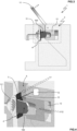
- shows a schematic cross-sectional view of a preparation machine including a cutting unit according to an embodiment to illustrate a step of preparing a beverage when the preparation chamber is closed;
- Fig.2
- shows a view similar to
Fig.1 to illustrate a step of reopening the preparation chamber shortly after the capsule has been processed in the preparation unit; - Fig.3
- shows a view similar to
Fig.1 to illustrate a step where the cutting element is cutting the capsule open; - Fig.4
- shows a schematic cutaway perspective view, cut along the same plane as
Fig.3 , of the detail IV inFig.3 ; - Fig.5
- shows a view similar to
Fig.1 where the cut capsule is transferred to the collecting chamber; - Fig.6
- shows a schematic cutaway perspective view, cut along the same plane as
Fig.5 , of the detail VI inFig.5 ; - Fig.7
- shows a view similar to
Fig.1 to illustrate a step where the cut capsule body and the released beverage component fall into the collecting chamber, with the preparation chamber fully open; - Fig.8
- shows a view similar to
Fig.1 to illustrate a final step after the cut capsule body and the released beverage component have reached the bottom of the collecting chamber, with the preparation chamber fully open; - Fig.9
- shows a flowchart of a method according to the present invention for preparing a beverage.
-
Figs.1-2 show apreparation machine 1 for preparing a beverage by injecting a fluid in acapsule 100. Thepreparation machine 1 may for example be of a Nespresso Essenza Mini® or a Nespresso Pixie®. Thecapsule 100 may for example be a Nespresso original®. - The
capsule 100 has i) acapsule body 101 defining acavity 102 and ii) a beverage component 103 (Figs.7-8 ) contained within thecavity 102. Thebeverage component 103 may be roast and ground coffee. Thecapsule body 101 may include a membrane 104 (Figs.7-8 ) configured to close thecavity 102. - The
preparation machine 1 comprises apreparation unit 2 and acutting unit 4. Thecutting unit 4 may be located beside thepreparation unit 2. As thecutting unit 4 is part of thepreparation machine 1, it provides an all-in-one compact equipment for processing the capsules and enhancing their disposability and recyclability. - The
preparation machine 1 may have an introduction duct 5 (Figs.1-2 ) for introducing thecapsule 100 into thebeverage preparation unit 2. Thepreparation unit 2 has a preparation chamber 6 (Figs.1-2 ), which is suitable for receiving thecapsule 100. Thepreparation chamber 6 may include a pyramid plate 6.1 covered with sharp pyramids configured to tear open the membrane 104 (Figs.7-8 ) to let the prepared beverage flow out of thecapsule 100. - The
preparation unit 2 also has a fluid injection unit 8 (shown only inFig.1 ), which may be configured for injecting the fluid in thecapsule 100 to prepare the beverage when the capsule is in thepreparation chamber 6. The fluid may be hot water under pressure. During preparation of a beverage (Fig.1 ), thebeverage component 103 may be made to interact with the fluid injected in thecapsule 100 in order to prepare a cup of coffee. - The
cutting unit 4 has acutting element 7. As visible inFig.4 , the cuttingelement 7 may comprise a blade, which may be substantially in the shape of a rectangle. As shown inFigs.3-4 , the cuttingelement 7 is movable to cut thecapsule 100 open, in order to release most or all of thebeverage component 103 from thecavity 102 after thecapsule 100 has been processed in thepreparation unit 2. - In the example of
Figs.1-8 , the cuttingelement 7 may be movable in translation, herein along a cutting direction Y7 that is substantially perpendicular to the plane ofFig.3 and to an axis of symmetry ofcapsule 100. The cuttingelement 7 may be arranged to pass through thepreparation chamber 6. - The
cutting unit 4 may have a counter-wall (not shown), which is arranged opposite the cuttingelement 7 with respect to thecapsule 100. Thus, the counter-wall can keep thecapsule 100 in contact with the cuttingelement 7 while thecapsule 100 is being cut by the cuttingelement 7. - In the example of
Figs.1-8 , thecapsule 100 may be positioned at substantially the same location it occupies during beverage preparation in thepreparation unit 2. Thecapsule 100 can be cut in two pieces, for example one including themembrane 104 and the other one including a main portion of thecapsule body 101. - The
preparation machine 1 may further comprise a driving unit 10 (shown only inFig.4 ), which is configured to move thecutting element 7 in translation along the cutting direction Y7. The drivingunit 10 may include a motor (not shown), which may be powered by the same source as thepreparation unit 2 and thefluid injection unit 8. - The driving
unit 10 may be mechanically connected with the cuttingelement 7 in order to transmit a mechanical force, possibly via a mechanism (not shown), to thecutting element 7. In turn, the cuttingelement 7 can cut thecapsule 100 as shown inFig.3-4 . - Thus, when the
cutting unit 4 is used in apreparation machine 1, the processedcapsule 100 can be cut by the cuttingelement 7 to release most or all of the usedbeverage component 103 from thecavity 102. - The
preparation machine 1 may further comprise a crank 11 which may be coupled to thepreparation unit 2, so as to manually displace amovable chamber section 12, and thus selectively open or close thepreparation chamber 6. As shown inFig.4 the cutting direction Y7 may be substantially perpendicular to the direction X12 along which themovable chamber section 12 is displace to close or open thepreparation chamber 6. - In
Fig.1 thecrank 11 is horizontally placed in a first end position as themovable chamber section 12 is closing thepreparation chamber 6. InFigs.2 ,3 and 4 thecrank 11 is placed in intermediate positions as thepreparation chamber 6 is reopened partly (Fig.2 ) and then fully (Figs.3-4 ). InFigs.5-6 thecrank 11 is in a vertical position as thepreparation chamber 6 is fully open. InFigs.7-8 thecrank 11 is placed in a second end position past the vertical position ofFigs.5-6 , which may trigger the return of the blade back towards its initial position. InFigs.7-8 themovable chamber section 12 is fully retracted, hence thepreparation chamber 6 is fully open. - As shown in
Fig.4 thecutting unit 4 may further have adrive connection 15 functionally connecting the cuttingelement 7 with the drivingunit 10 to selectively move thecutting element 7, here in translation along the cutting direction Y12. - As shown in
Figs.7-8 , in addition to thecutting unit 4, thepreparation machine 1 may comprise aseparation unit 16, which is configured to let the openedcapsule body 101 separate from the releasedbeverage component 103. Theseparation unit 16 can receive the openedcapsule 101 and thebeverage component 103 from thecutting unit 4. In the example ofFigs.1-8 , the openedcapsule body 101 may separate from the releasedbeverage component 103 simply by the action of gravity, while falling through theseparation unit 16. - As shown in
Figs.7-8 thepreparation machine 1 may further comprise a collectingchamber 20 configured for collecting the releasedbeverage component 103 and thecut capsule body 101 together, the collectingchamber 20 thus forming a common container. As thecutting element 7 cut through thecapsule body 101 to cut thecapsule 100 open, thecapsule body 101 may be separated in two pieces, which roughly correspond to themembrane 104 and to the rest ofcapsule body 101. Thecavity 102 can be emptied and thebeverage component 103 can be separated from the openedcapsule body 101. - In the example of
Figs.1-8 , the collectingchamber 20 may be located below theseparation unit 16. The collectingchamber 20 may be integral with theseparation unit 16, so the user can conveniently detach and reattach them altogether. Thus, the user can conveniently handle the releasedbeverage component 103 and thecut capsule body 101, and then empty the collectingchamber 20. - The
preparation unit 2 may be detachably coupled to theseparation unit 16 and the collectingchamber 20. Thecutting unit 4, theseparation unit 16 and/or the collectingchamber 20 may be detached from thepreparation unit 2 by translation parallel to closing direction X12. - The
cutting unit 4 may have a slot (not shown) configured to accommodate partly or totally the cuttingelement 7. The slot may have a shape complementary to the shape of the cuttingelement 7, with some clearance. - The
cutting unit 4 may be accommodated in thepreparation unit 2. Thepreparation machine 2 may have anaccommodating space 23 for accommodating most or all of theseparation unit 16 and of the collectingchamber 20. Theaccommodating space 23 may be formed by a cavity located under thepreparation unit 2. - The
preparation machine 1 may further comprise coupling means (not shown) for detachably coupling thecutting unit 4 and/or theseparation unit 16 to thepreparation unit 2. Thepreparation machine 1 may further comprise locking means (not shown) for locking thecutting unit 4 and/or theseparation unit 16 to thepreparation unit 2. The locking means may preferably be configured for reversible elastic snap-fitting of said units on one another. - As shown in
Figs.5-6 thepreparation machine 1 may further comprise atransfer section 25 for allowing a transfer, by the action of gravity, of thecapsule 100 from thepreparation chamber 2 to theseparation unit 16. InFigs.5-6 thecapsule 100 is passing through thetransfer section 25. Thetransfer section 25 may be a passage, which is joining thepreparation chamber 6 to theseparation unit 16 and which is oriented substantially vertically. After thepreparation chamber 6 is fully open, the processed and cutcapsule 100 is free to fall throughtransfer section 25 and into theseparation unit 16. - The
cutting unit 4 may further comprise a cleaning device 26 (shown only inFig.1 ) for rinsing thecapsule body 101 with fluid after thecapsule 100 has been processed in thepreparation unit 2. Thecleaning device 26 can enhance removal ofbeverage component 103 from the openedcapsule 101. Thecleaning device 26 may be fluidly connected with thefluid injection unit 8 for a supply of fluid, for example water. Thecleaning device 26 may be arranged downstream thecutting unit 4. The collectingchamber 20 may be configured to collect also the rinsing fluid after the rinsing has been carried out. - In addition or alternatively to the
cleaning device 26, thepreparation machine 1 may further comprise a drying module (not shown) configured for partly or totally dry out the beverage component. The drying module may be part of theseparation unit 16. Thus, the drying module can enhance the separation of thebeverage component 103 from thecapsule body 101. - The
preparation machine 1 may further comprise a dispensingunit 28 for dispensing the beverage out of thepreparation unit 2. The dispensingunit 28 may be fluidly connected with thepreparation chamber 6 and have a duct for guiding the beverage out of thepreparation machine 1. The dispensingunit 28 may further have a fillingspace 30 where a drinking cup of a user may be placed such that the beverage can be dispensed therein. The fillingspace 30 may be located in front of theseparation unit 16. - The collecting
chamber 20 may further comprise level sensors (not shown), which are configured to issue respective signals representing the (full) level ofbeverage component 103 and of pieces ofcapsule body 101 in the collectingchamber 20. Upon receiving such signals the user can detach the collecting chamber 20 (or the whole separation unit 16), empty it, and then reattach it to thepreparation unit 2. - When the
preparation machine 1 is in service, it can be operated to prepare a beverage according to amethod 200 illustrated in Fig.13. Themethod 200 comprises: - 202) receiving a
capsule 100 in thepreparation chamber 6, - 204) preparing a beverage by injecting the fluid in the
capsule 100 such that the fluid interacts with thebeverage component 103, - 206) preferably, transferring the
capsule 100, via thetransfer section 25, from thepreparation unit 2 to thecutting unit 4 after thecapsule 100 has been processed in thepreparation unit 2, and - 208) let the cutting
element 7 cut thecapsule 100 open such that at least part of thebeverage component 103 is released from thecavity 102. - The user can thus easily handle the released
beverage component 103 separately from the openedcapsule 100. The disposability and recyclability of processedcapsules 100 is enhanced. For example, thebeverage component 103 can be composted at home. - Further, the
method 200 may further comprise: - 210) separating, by means of
separation unit 16, the openedcapsule 101 from the releasedbeverage component 103, wherein theseparation unit 16 may be located downstream thecutting unit 4; - 212) actuating a
cleaning device 26 to rinse the openedcapsule body 101 by means of fluid; and - 214) collecting in the collecting
chamber 20 the releasedbeverage component 103 and the openedcapsule body 101. - As long as the present invention remains covered by the appended claims, the present invention is not limited to the afore-described aspects, embodiments and implementations, most of which may be combined.
Claims (15)
- Preparation machine (1) for preparing a beverage by injecting a fluid in a capsule (100), the capsule (100) having i) a capsule body (101) defining a cavity (102) and ii) a beverage component (103) contained within the cavity (102), wherein the preparation machine (1) comprises:- a preparation unit (2) having i) a preparation chamber (6) for receiving the capsule (100) and ii) a fluid injection unit (8) for injecting the fluid in the capsule (100) to prepare the beverage, and- a cutting unit (4) having a cutting element (7), the cutting element (7) being configured to cut the capsule (100) open such that at least part of the beverage component (103) is released from the cavity (102) after the capsule (100) has been processed in the preparation unit (2).
- Preparation machine (1) according to claim 1, wherein the cutting element (7) comprises a blade.
- Preparation machine (1) according to any one of the preceding claims, further comprising a driving unit (10) configured to move the cutting element (7) to cut open the capsule (100), the driving unit (10) including a motor or a manual actuator.
- Preparation machine (1) according to any one of the preceding claims, wherein the cutting element (7) is movable in translation.
- Preparation machine (1) according to any one of any one of the preceding claims, wherein the cutting element (7) is arranged to pass at least partially through the preparation chamber (6).
- Preparation machine (1) according to any one of the preceding claims, further comprising a separation unit (16) configured to let the opened capsule body (101) separate from the beverage component (103) released from the cavity (102).
- Preparation machine (1) according to claim 6, wherein the separation unit (16) comprises a filtering grid (18) configured to retain the opened capsule body (101) and to let all or part of the beverage component (103) released from the cavity (102) pass through the filtering grid (18).
- Preparation machine (1) according to any one of the preceding claims, further comprising a collecting chamber (20) for collecting the beverage component (103) released from the cavity (102) and the opened capsule body (101), preferably in separate sections (21, 22) of the collecting chamber (20), the collecting chamber (20) being preferably part of the cutting unit (4) or of the separation unit (16) if present.
- Preparation machine (1) according to any one of the preceding claims, further comprising a transfer section (25) configured to allow a defined transfer, preferably by the action of gravity, of the capsule (100) from the preparation chamber (6) to the cutting unit (4).
- Preparation machine (1) according to any one of claims 6 to 9, wherein the preparation chamber (2) is arranged above the separation unit (16) if present and/or above the collection chamber (20) if present, such that the opened capsule body (101) and the beverage component (103) released from the cavity (102) can be transferred to the separation unit (16) if present and/or to the collection chamber (20) if present by the action of gravity.
- Preparation machine (1) according to any one of the preceding claims, wherein the preparation unit (2) is detachably coupled to the cutting unit (4), to the separation unit (16) if present, and/or to the collecting chamber (20) if present.
- Preparation machine (1) according to any one of the preceding claims, wherein the cutting unit (4) further comprises a cleaning device (26), the cleaning device (26) being fluidly connected with the fluid injection unit (8), the cleaning device (26) being configured to rinse the opened capsule body (101) with some of the fluid after the capsule (100) has been processed in the preparation unit (2), the cleaning device (26) being arranged downstream the cutting unit (4).
- Preparation machine (1) according to any one of the preceding claims, further comprising a dispensing unit (28) for dispensing the beverage out of the preparation unit (2).
- Cutting unit (4) for being used in a preparation machine (1) according to any one of the preceding claims, the cutting unit (4) being configured to be coupled, preferably in a detachable manner, to the preparation unit (2) such that the capsule (100) may be transferred from the preparation chamber (6) to the cutting unit (4), the cutting unit (4) having i) the cutting element (7) and ii) a drive connection for functionally connecting the cutting element (7) with a or the driving unit of the preparation machine (1) to selectively move the cutting element (7).
- Method (200) for preparing a beverage with a preparation machine (1) according to any one of claims 1 to 13, the method (200) comprising:- 202) receiving a capsule (100) in the preparation chamber (6),- 204) preparing a beverage by injecting the fluid in the capsule (100) such that the fluid interacts with the beverage component (103),- 206) preferably, transferring the capsule (100) from the preparation unit (2) to the cutting unit (4) after the capsule (100) has been processed in the preparation unit (2), and- 208) let the cutting element (7) cut the capsule (100) open such that at least part of the beverage component (103) is released from the cavity (102).
Priority Applications (1)
| Application Number | Priority Date | Filing Date | Title |
|---|---|---|---|
| EP23185515.6A EP4491070B1 (en) | 2023-07-14 | 2023-07-14 | Machine, cutting unit for such a machine and method for preparing a beverage with such a machine |
Applications Claiming Priority (1)
| Application Number | Priority Date | Filing Date | Title |
|---|---|---|---|
| EP23185515.6A EP4491070B1 (en) | 2023-07-14 | 2023-07-14 | Machine, cutting unit for such a machine and method for preparing a beverage with such a machine |
Publications (2)
| Publication Number | Publication Date |
|---|---|
| EP4491070A1 true EP4491070A1 (en) | 2025-01-15 |
| EP4491070B1 EP4491070B1 (en) | 2026-07-08 |
Family
ID=87340736
Family Applications (1)
| Application Number | Title | Priority Date | Filing Date |
|---|---|---|---|
| EP23185515.6A Active EP4491070B1 (en) | 2023-07-14 | 2023-07-14 | Machine, cutting unit for such a machine and method for preparing a beverage with such a machine |
Country Status (1)
| Country | Link |
|---|---|
| EP (1) | EP4491070B1 (en) |
Citations (5)
| Publication number | Priority date | Publication date | Assignee | Title |
|---|---|---|---|---|
| US20030116029A1 (en) * | 2000-06-30 | 2003-06-26 | Nestec S.A. | Capsule cage |
| WO2011051867A1 (en) * | 2009-10-26 | 2011-05-05 | Massimiliano Pineschi | A separating device for machines for preparing beverages |
| ITMI20101096A1 (en) * | 2010-06-17 | 2011-12-18 | M R & D Inst S R L | WAFFLE TREATMENT DEVICE USED FOR COFFEE PREPARATION AND OTHER HOT DRINKS |
| EP2291312B1 (en) * | 2008-06-20 | 2013-07-24 | Nestec S.A. | Use of a capsule treatment apparatus |
| US20210068580A1 (en) * | 2018-03-29 | 2021-03-11 | Illycaffe' S.P.A. | Used capsule disposal assembly |
-
2023
- 2023-07-14 EP EP23185515.6A patent/EP4491070B1/en active Active
Patent Citations (5)
| Publication number | Priority date | Publication date | Assignee | Title |
|---|---|---|---|---|
| US20030116029A1 (en) * | 2000-06-30 | 2003-06-26 | Nestec S.A. | Capsule cage |
| EP2291312B1 (en) * | 2008-06-20 | 2013-07-24 | Nestec S.A. | Use of a capsule treatment apparatus |
| WO2011051867A1 (en) * | 2009-10-26 | 2011-05-05 | Massimiliano Pineschi | A separating device for machines for preparing beverages |
| ITMI20101096A1 (en) * | 2010-06-17 | 2011-12-18 | M R & D Inst S R L | WAFFLE TREATMENT DEVICE USED FOR COFFEE PREPARATION AND OTHER HOT DRINKS |
| US20210068580A1 (en) * | 2018-03-29 | 2021-03-11 | Illycaffe' S.P.A. | Used capsule disposal assembly |
Also Published As
| Publication number | Publication date |
|---|---|
| EP4491070B1 (en) | 2026-07-08 |
Similar Documents
| Publication | Publication Date | Title |
|---|---|---|
| JP6998299B2 (en) | Beverage machine with ergonomic outlet | |
| JP5394389B2 (en) | Used capsule or pod container for liquid food or beverage preparation equipment | |
| CN107117398B (en) | Capsule for beverage | |
| JP6910344B2 (en) | Beverage machine with ergonomic user interface | |
| JP5570521B2 (en) | System, package, apparatus and method for quantitatively supplying coffee beans | |
| AU2008355536B2 (en) | An automatic pod conveyor and brewer assembly for fresh hot beverage | |
| CN109640683B (en) | Separation device, grinding device, and beverage production device | |
| US11759046B2 (en) | Used capsule disposal assembly | |
| WO2011051867A1 (en) | A separating device for machines for preparing beverages | |
| CN102076249B (en) | Brewer with Substance Removal Components | |
| CA2847965C (en) | Method and device for producing a coffee preparation | |
| JP2011526535A (en) | Capsule processing equipment | |
| MXPA02010991A (en) | Device for extracting a substance. | |
| CN105640336A (en) | System for preparing coffee beverage | |
| US6640701B2 (en) | Apparatus for compacting and draining mixed waste in passenger transport vehicles | |
| CN111867743B (en) | Used capsule handling assembly | |
| EP2604547A1 (en) | A capsule for descaling a beverage preparation machine | |
| CN110996731A (en) | Beverage making device | |
| CN109843748B (en) | A handcart, waste module and system for collecting waste | |
| CN117813032A (en) | beverage preparation system | |
| EP4491069B1 (en) | Machine, deformation unit for such a machine and method for preparing a beverage with such a machine | |
| EP4491068A1 (en) | Machine, crushing unit for such a machine and method for preparing a beverage with such a machine | |
| JP2025512894A (en) | Beverage Preparation Systems | |
| US10285533B2 (en) | Food preparation system | |
| DE102018127644A1 (en) | Beverage maker, catcher and beverage maker system |
Legal Events
| Date | Code | Title | Description |
|---|---|---|---|
| PUAI | Public reference made under article 153(3) epc to a published international application that has entered the european phase |
Free format text: ORIGINAL CODE: 0009012 |
|
| STAA | Information on the status of an ep patent application or granted ep patent |
Free format text: STATUS: THE APPLICATION HAS BEEN PUBLISHED |
|
| AK | Designated contracting states |
Kind code of ref document: A1 Designated state(s): AL AT BE BG CH CY CZ DE DK EE ES FI FR GB GR HR HU IE IS IT LI LT LU LV MC ME MK MT NL NO PL PT RO RS SE SI SK SM TR |
|
| P01 | Opt-out of the competence of the unified patent court (upc) registered |
Free format text: CASE NUMBER: APP_11480/2025 Effective date: 20250310 |
|
| STAA | Information on the status of an ep patent application or granted ep patent |
Free format text: STATUS: REQUEST FOR EXAMINATION WAS MADE |
|
| 17P | Request for examination filed |
Effective date: 20250715 |
|
| STAA | Information on the status of an ep patent application or granted ep patent |
Free format text: STATUS: EXAMINATION IS IN PROGRESS |
|
| 17Q | First examination report despatched |
Effective date: 20250828 |
|
| GRAP | Despatch of communication of intention to grant a patent |
Free format text: ORIGINAL CODE: EPIDOSNIGR1 |
|
| STAA | Information on the status of an ep patent application or granted ep patent |
Free format text: STATUS: GRANT OF PATENT IS INTENDED |
|
| INTG | Intention to grant announced |
Effective date: 20260302 |
|
| GRAS | Grant fee paid |
Free format text: ORIGINAL CODE: EPIDOSNIGR3 |
|
| GRAA | (expected) grant |
Free format text: ORIGINAL CODE: 0009210 |
|
| STAA | Information on the status of an ep patent application or granted ep patent |
Free format text: STATUS: THE PATENT HAS BEEN GRANTED |
|
| AK | Designated contracting states |
Kind code of ref document: B1 Designated state(s): AL AT BE BG CH CY CZ DE DK EE ES FI FR GB GR HR HU IE IS IT LI LT LU LV MC ME MK MT NL NO PL PT RO RS SE SI SK SM TR |
|
| REG | Reference to a national code |
Ref country code: CH Ref legal event code: F10 Free format text: ST27 STATUS EVENT CODE: U-0-0-F10-F00 (AS PROVIDED BY THE NATIONAL OFFICE) Effective date: 20260708 Ref country code: GB Ref legal event code: FG4D |
|
| REG | Reference to a national code |
Ref country code: DE Ref legal event code: R096 Ref document number: 602023019493 Country of ref document: DE |
|
| REG | Reference to a national code |
Ref country code: IE Ref legal event code: FG4D |