EP4490427B1 - Dispositif aeronautique demontable de stockage de gaz liquefie - Google Patents
Dispositif aeronautique demontable de stockage de gaz liquefie Download PDFInfo
- Publication number
- EP4490427B1 EP4490427B1 EP23725265.5A EP23725265A EP4490427B1 EP 4490427 B1 EP4490427 B1 EP 4490427B1 EP 23725265 A EP23725265 A EP 23725265A EP 4490427 B1 EP4490427 B1 EP 4490427B1
- Authority
- EP
- European Patent Office
- Prior art keywords
- inner container
- pressure
- outer envelope
- gas
- valve
- Prior art date
- Legal status (The legal status is an assumption and is not a legal conclusion. Google has not performed a legal analysis and makes no representation as to the accuracy of the status listed.)
- Active
Links
Images




Classifications
-
- F—MECHANICAL ENGINEERING; LIGHTING; HEATING; WEAPONS; BLASTING
- F17—STORING OR DISTRIBUTING GASES OR LIQUIDS
- F17C—VESSELS FOR CONTAINING OR STORING COMPRESSED, LIQUEFIED OR SOLIDIFIED GASES; FIXED-CAPACITY GAS-HOLDERS; FILLING VESSELS WITH, OR DISCHARGING FROM VESSELS, COMPRESSED, LIQUEFIED, OR SOLIDIFIED GASES
- F17C3/00—Vessels not under pressure
- F17C3/02—Vessels not under pressure with provision for thermal insulation
- F17C3/04—Vessels not under pressure with provision for thermal insulation by insulating layers
-
- F—MECHANICAL ENGINEERING; LIGHTING; HEATING; WEAPONS; BLASTING
- F17—STORING OR DISTRIBUTING GASES OR LIQUIDS
- F17C—VESSELS FOR CONTAINING OR STORING COMPRESSED, LIQUEFIED OR SOLIDIFIED GASES; FIXED-CAPACITY GAS-HOLDERS; FILLING VESSELS WITH, OR DISCHARGING FROM VESSELS, COMPRESSED, LIQUEFIED, OR SOLIDIFIED GASES
- F17C3/00—Vessels not under pressure
-
- F—MECHANICAL ENGINEERING; LIGHTING; HEATING; WEAPONS; BLASTING
- F17—STORING OR DISTRIBUTING GASES OR LIQUIDS
- F17C—VESSELS FOR CONTAINING OR STORING COMPRESSED, LIQUEFIED OR SOLIDIFIED GASES; FIXED-CAPACITY GAS-HOLDERS; FILLING VESSELS WITH, OR DISCHARGING FROM VESSELS, COMPRESSED, LIQUEFIED, OR SOLIDIFIED GASES
- F17C2201/00—Vessel construction, in particular geometry, arrangement or size
- F17C2201/01—Shape
- F17C2201/0104—Shape cylindrical
- F17C2201/0109—Shape cylindrical with exteriorly curved end-piece
-
- F—MECHANICAL ENGINEERING; LIGHTING; HEATING; WEAPONS; BLASTING
- F17—STORING OR DISTRIBUTING GASES OR LIQUIDS
- F17C—VESSELS FOR CONTAINING OR STORING COMPRESSED, LIQUEFIED OR SOLIDIFIED GASES; FIXED-CAPACITY GAS-HOLDERS; FILLING VESSELS WITH, OR DISCHARGING FROM VESSELS, COMPRESSED, LIQUEFIED, OR SOLIDIFIED GASES
- F17C2201/00—Vessel construction, in particular geometry, arrangement or size
- F17C2201/01—Shape
- F17C2201/0128—Shape spherical or elliptical
-
- F—MECHANICAL ENGINEERING; LIGHTING; HEATING; WEAPONS; BLASTING
- F17—STORING OR DISTRIBUTING GASES OR LIQUIDS
- F17C—VESSELS FOR CONTAINING OR STORING COMPRESSED, LIQUEFIED OR SOLIDIFIED GASES; FIXED-CAPACITY GAS-HOLDERS; FILLING VESSELS WITH, OR DISCHARGING FROM VESSELS, COMPRESSED, LIQUEFIED, OR SOLIDIFIED GASES
- F17C2201/00—Vessel construction, in particular geometry, arrangement or size
- F17C2201/03—Orientation
- F17C2201/035—Orientation with substantially horizontal main axis
-
- F—MECHANICAL ENGINEERING; LIGHTING; HEATING; WEAPONS; BLASTING
- F17—STORING OR DISTRIBUTING GASES OR LIQUIDS
- F17C—VESSELS FOR CONTAINING OR STORING COMPRESSED, LIQUEFIED OR SOLIDIFIED GASES; FIXED-CAPACITY GAS-HOLDERS; FILLING VESSELS WITH, OR DISCHARGING FROM VESSELS, COMPRESSED, LIQUEFIED, OR SOLIDIFIED GASES
- F17C2201/00—Vessel construction, in particular geometry, arrangement or size
- F17C2201/05—Size
- F17C2201/054—Size medium (>1 m3)
-
- F—MECHANICAL ENGINEERING; LIGHTING; HEATING; WEAPONS; BLASTING
- F17—STORING OR DISTRIBUTING GASES OR LIQUIDS
- F17C—VESSELS FOR CONTAINING OR STORING COMPRESSED, LIQUEFIED OR SOLIDIFIED GASES; FIXED-CAPACITY GAS-HOLDERS; FILLING VESSELS WITH, OR DISCHARGING FROM VESSELS, COMPRESSED, LIQUEFIED, OR SOLIDIFIED GASES
- F17C2201/00—Vessel construction, in particular geometry, arrangement or size
- F17C2201/05—Size
- F17C2201/056—Small (<1 m3)
-
- F—MECHANICAL ENGINEERING; LIGHTING; HEATING; WEAPONS; BLASTING
- F17—STORING OR DISTRIBUTING GASES OR LIQUIDS
- F17C—VESSELS FOR CONTAINING OR STORING COMPRESSED, LIQUEFIED OR SOLIDIFIED GASES; FIXED-CAPACITY GAS-HOLDERS; FILLING VESSELS WITH, OR DISCHARGING FROM VESSELS, COMPRESSED, LIQUEFIED, OR SOLIDIFIED GASES
- F17C2203/00—Vessel construction, in particular walls or details thereof
- F17C2203/01—Reinforcing or suspension means
- F17C2203/011—Reinforcing means
- F17C2203/012—Reinforcing means on or in the wall, e.g. ribs
-
- F—MECHANICAL ENGINEERING; LIGHTING; HEATING; WEAPONS; BLASTING
- F17—STORING OR DISTRIBUTING GASES OR LIQUIDS
- F17C—VESSELS FOR CONTAINING OR STORING COMPRESSED, LIQUEFIED OR SOLIDIFIED GASES; FIXED-CAPACITY GAS-HOLDERS; FILLING VESSELS WITH, OR DISCHARGING FROM VESSELS, COMPRESSED, LIQUEFIED, OR SOLIDIFIED GASES
- F17C2203/00—Vessel construction, in particular walls or details thereof
- F17C2203/01—Reinforcing or suspension means
- F17C2203/011—Reinforcing means
- F17C2203/013—Reinforcing means in the vessel, e.g. columns
-
- F—MECHANICAL ENGINEERING; LIGHTING; HEATING; WEAPONS; BLASTING
- F17—STORING OR DISTRIBUTING GASES OR LIQUIDS
- F17C—VESSELS FOR CONTAINING OR STORING COMPRESSED, LIQUEFIED OR SOLIDIFIED GASES; FIXED-CAPACITY GAS-HOLDERS; FILLING VESSELS WITH, OR DISCHARGING FROM VESSELS, COMPRESSED, LIQUEFIED, OR SOLIDIFIED GASES
- F17C2203/00—Vessel construction, in particular walls or details thereof
- F17C2203/03—Thermal insulations
- F17C2203/0304—Thermal insulations by solid means
-
- F—MECHANICAL ENGINEERING; LIGHTING; HEATING; WEAPONS; BLASTING
- F17—STORING OR DISTRIBUTING GASES OR LIQUIDS
- F17C—VESSELS FOR CONTAINING OR STORING COMPRESSED, LIQUEFIED OR SOLIDIFIED GASES; FIXED-CAPACITY GAS-HOLDERS; FILLING VESSELS WITH, OR DISCHARGING FROM VESSELS, COMPRESSED, LIQUEFIED, OR SOLIDIFIED GASES
- F17C2203/00—Vessel construction, in particular walls or details thereof
- F17C2203/06—Materials for walls or layers thereof; Properties or structures of walls or their materials
- F17C2203/0602—Wall structures; Special features thereof
- F17C2203/0604—Liners
-
- F—MECHANICAL ENGINEERING; LIGHTING; HEATING; WEAPONS; BLASTING
- F17—STORING OR DISTRIBUTING GASES OR LIQUIDS
- F17C—VESSELS FOR CONTAINING OR STORING COMPRESSED, LIQUEFIED OR SOLIDIFIED GASES; FIXED-CAPACITY GAS-HOLDERS; FILLING VESSELS WITH, OR DISCHARGING FROM VESSELS, COMPRESSED, LIQUEFIED, OR SOLIDIFIED GASES
- F17C2203/00—Vessel construction, in particular walls or details thereof
- F17C2203/06—Materials for walls or layers thereof; Properties or structures of walls or their materials
- F17C2203/0602—Wall structures; Special features thereof
- F17C2203/0612—Wall structures
- F17C2203/0626—Multiple walls
- F17C2203/0629—Two walls
-
- F—MECHANICAL ENGINEERING; LIGHTING; HEATING; WEAPONS; BLASTING
- F17—STORING OR DISTRIBUTING GASES OR LIQUIDS
- F17C—VESSELS FOR CONTAINING OR STORING COMPRESSED, LIQUEFIED OR SOLIDIFIED GASES; FIXED-CAPACITY GAS-HOLDERS; FILLING VESSELS WITH, OR DISCHARGING FROM VESSELS, COMPRESSED, LIQUEFIED, OR SOLIDIFIED GASES
- F17C2203/00—Vessel construction, in particular walls or details thereof
- F17C2203/06—Materials for walls or layers thereof; Properties or structures of walls or their materials
- F17C2203/0634—Materials for walls or layers thereof
- F17C2203/0636—Metals
- F17C2203/0639—Steels
- F17C2203/0643—Stainless steels
-
- F—MECHANICAL ENGINEERING; LIGHTING; HEATING; WEAPONS; BLASTING
- F17—STORING OR DISTRIBUTING GASES OR LIQUIDS
- F17C—VESSELS FOR CONTAINING OR STORING COMPRESSED, LIQUEFIED OR SOLIDIFIED GASES; FIXED-CAPACITY GAS-HOLDERS; FILLING VESSELS WITH, OR DISCHARGING FROM VESSELS, COMPRESSED, LIQUEFIED, OR SOLIDIFIED GASES
- F17C2203/00—Vessel construction, in particular walls or details thereof
- F17C2203/06—Materials for walls or layers thereof; Properties or structures of walls or their materials
- F17C2203/0634—Materials for walls or layers thereof
- F17C2203/0636—Metals
- F17C2203/0646—Aluminium
-
- F—MECHANICAL ENGINEERING; LIGHTING; HEATING; WEAPONS; BLASTING
- F17—STORING OR DISTRIBUTING GASES OR LIQUIDS
- F17C—VESSELS FOR CONTAINING OR STORING COMPRESSED, LIQUEFIED OR SOLIDIFIED GASES; FIXED-CAPACITY GAS-HOLDERS; FILLING VESSELS WITH, OR DISCHARGING FROM VESSELS, COMPRESSED, LIQUEFIED, OR SOLIDIFIED GASES
- F17C2203/00—Vessel construction, in particular walls or details thereof
- F17C2203/06—Materials for walls or layers thereof; Properties or structures of walls or their materials
- F17C2203/0634—Materials for walls or layers thereof
- F17C2203/0636—Metals
- F17C2203/0648—Alloys or compositions of metals
-
- F—MECHANICAL ENGINEERING; LIGHTING; HEATING; WEAPONS; BLASTING
- F17—STORING OR DISTRIBUTING GASES OR LIQUIDS
- F17C—VESSELS FOR CONTAINING OR STORING COMPRESSED, LIQUEFIED OR SOLIDIFIED GASES; FIXED-CAPACITY GAS-HOLDERS; FILLING VESSELS WITH, OR DISCHARGING FROM VESSELS, COMPRESSED, LIQUEFIED, OR SOLIDIFIED GASES
- F17C2203/00—Vessel construction, in particular walls or details thereof
- F17C2203/06—Materials for walls or layers thereof; Properties or structures of walls or their materials
- F17C2203/0634—Materials for walls or layers thereof
- F17C2203/0658—Synthetics
- F17C2203/0663—Synthetics in form of fibers or filaments
-
- F—MECHANICAL ENGINEERING; LIGHTING; HEATING; WEAPONS; BLASTING
- F17—STORING OR DISTRIBUTING GASES OR LIQUIDS
- F17C—VESSELS FOR CONTAINING OR STORING COMPRESSED, LIQUEFIED OR SOLIDIFIED GASES; FIXED-CAPACITY GAS-HOLDERS; FILLING VESSELS WITH, OR DISCHARGING FROM VESSELS, COMPRESSED, LIQUEFIED, OR SOLIDIFIED GASES
- F17C2203/00—Vessel construction, in particular walls or details thereof
- F17C2203/06—Materials for walls or layers thereof; Properties or structures of walls or their materials
- F17C2203/0634—Materials for walls or layers thereof
- F17C2203/0658—Synthetics
- F17C2203/0675—Synthetics with details of composition
-
- F—MECHANICAL ENGINEERING; LIGHTING; HEATING; WEAPONS; BLASTING
- F17—STORING OR DISTRIBUTING GASES OR LIQUIDS
- F17C—VESSELS FOR CONTAINING OR STORING COMPRESSED, LIQUEFIED OR SOLIDIFIED GASES; FIXED-CAPACITY GAS-HOLDERS; FILLING VESSELS WITH, OR DISCHARGING FROM VESSELS, COMPRESSED, LIQUEFIED, OR SOLIDIFIED GASES
- F17C2205/00—Vessel construction, in particular mounting arrangements, attachments or identifications means
- F17C2205/01—Mounting arrangements
- F17C2205/0103—Exterior arrangements
- F17C2205/0107—Frames
-
- F—MECHANICAL ENGINEERING; LIGHTING; HEATING; WEAPONS; BLASTING
- F17—STORING OR DISTRIBUTING GASES OR LIQUIDS
- F17C—VESSELS FOR CONTAINING OR STORING COMPRESSED, LIQUEFIED OR SOLIDIFIED GASES; FIXED-CAPACITY GAS-HOLDERS; FILLING VESSELS WITH, OR DISCHARGING FROM VESSELS, COMPRESSED, LIQUEFIED, OR SOLIDIFIED GASES
- F17C2205/00—Vessel construction, in particular mounting arrangements, attachments or identifications means
- F17C2205/01—Mounting arrangements
- F17C2205/0123—Mounting arrangements characterised by number of vessels
- F17C2205/013—Two or more vessels
- F17C2205/0134—Two or more vessels characterised by the presence of fluid connection between vessels
-
- F—MECHANICAL ENGINEERING; LIGHTING; HEATING; WEAPONS; BLASTING
- F17—STORING OR DISTRIBUTING GASES OR LIQUIDS
- F17C—VESSELS FOR CONTAINING OR STORING COMPRESSED, LIQUEFIED OR SOLIDIFIED GASES; FIXED-CAPACITY GAS-HOLDERS; FILLING VESSELS WITH, OR DISCHARGING FROM VESSELS, COMPRESSED, LIQUEFIED, OR SOLIDIFIED GASES
- F17C2205/00—Vessel construction, in particular mounting arrangements, attachments or identifications means
- F17C2205/01—Mounting arrangements
- F17C2205/0123—Mounting arrangements characterised by number of vessels
- F17C2205/013—Two or more vessels
- F17C2205/0134—Two or more vessels characterised by the presence of fluid connection between vessels
- F17C2205/0146—Two or more vessels characterised by the presence of fluid connection between vessels with details of the manifold
-
- F—MECHANICAL ENGINEERING; LIGHTING; HEATING; WEAPONS; BLASTING
- F17—STORING OR DISTRIBUTING GASES OR LIQUIDS
- F17C—VESSELS FOR CONTAINING OR STORING COMPRESSED, LIQUEFIED OR SOLIDIFIED GASES; FIXED-CAPACITY GAS-HOLDERS; FILLING VESSELS WITH, OR DISCHARGING FROM VESSELS, COMPRESSED, LIQUEFIED, OR SOLIDIFIED GASES
- F17C2205/00—Vessel construction, in particular mounting arrangements, attachments or identifications means
- F17C2205/03—Fluid connections, filters, valves, closure means or other attachments
- F17C2205/0302—Fittings, valves, filters, or components in connection with the gas storage device
- F17C2205/0311—Closure means
- F17C2205/0314—Closure means breakable, e.g. with burst discs
-
- F—MECHANICAL ENGINEERING; LIGHTING; HEATING; WEAPONS; BLASTING
- F17—STORING OR DISTRIBUTING GASES OR LIQUIDS
- F17C—VESSELS FOR CONTAINING OR STORING COMPRESSED, LIQUEFIED OR SOLIDIFIED GASES; FIXED-CAPACITY GAS-HOLDERS; FILLING VESSELS WITH, OR DISCHARGING FROM VESSELS, COMPRESSED, LIQUEFIED, OR SOLIDIFIED GASES
- F17C2205/00—Vessel construction, in particular mounting arrangements, attachments or identifications means
- F17C2205/03—Fluid connections, filters, valves, closure means or other attachments
- F17C2205/0302—Fittings, valves, filters, or components in connection with the gas storage device
- F17C2205/0323—Valves
-
- F—MECHANICAL ENGINEERING; LIGHTING; HEATING; WEAPONS; BLASTING
- F17—STORING OR DISTRIBUTING GASES OR LIQUIDS
- F17C—VESSELS FOR CONTAINING OR STORING COMPRESSED, LIQUEFIED OR SOLIDIFIED GASES; FIXED-CAPACITY GAS-HOLDERS; FILLING VESSELS WITH, OR DISCHARGING FROM VESSELS, COMPRESSED, LIQUEFIED, OR SOLIDIFIED GASES
- F17C2205/00—Vessel construction, in particular mounting arrangements, attachments or identifications means
- F17C2205/03—Fluid connections, filters, valves, closure means or other attachments
- F17C2205/0302—Fittings, valves, filters, or components in connection with the gas storage device
- F17C2205/0323—Valves
- F17C2205/0326—Valves electrically actuated
-
- F—MECHANICAL ENGINEERING; LIGHTING; HEATING; WEAPONS; BLASTING
- F17—STORING OR DISTRIBUTING GASES OR LIQUIDS
- F17C—VESSELS FOR CONTAINING OR STORING COMPRESSED, LIQUEFIED OR SOLIDIFIED GASES; FIXED-CAPACITY GAS-HOLDERS; FILLING VESSELS WITH, OR DISCHARGING FROM VESSELS, COMPRESSED, LIQUEFIED, OR SOLIDIFIED GASES
- F17C2205/00—Vessel construction, in particular mounting arrangements, attachments or identifications means
- F17C2205/03—Fluid connections, filters, valves, closure means or other attachments
- F17C2205/0302—Fittings, valves, filters, or components in connection with the gas storage device
- F17C2205/0323—Valves
- F17C2205/0332—Safety valves or pressure relief valves
-
- F—MECHANICAL ENGINEERING; LIGHTING; HEATING; WEAPONS; BLASTING
- F17—STORING OR DISTRIBUTING GASES OR LIQUIDS
- F17C—VESSELS FOR CONTAINING OR STORING COMPRESSED, LIQUEFIED OR SOLIDIFIED GASES; FIXED-CAPACITY GAS-HOLDERS; FILLING VESSELS WITH, OR DISCHARGING FROM VESSELS, COMPRESSED, LIQUEFIED, OR SOLIDIFIED GASES
- F17C2205/00—Vessel construction, in particular mounting arrangements, attachments or identifications means
- F17C2205/03—Fluid connections, filters, valves, closure means or other attachments
- F17C2205/0302—Fittings, valves, filters, or components in connection with the gas storage device
- F17C2205/0323—Valves
- F17C2205/0335—Check-valves or non-return valves
-
- F—MECHANICAL ENGINEERING; LIGHTING; HEATING; WEAPONS; BLASTING
- F17—STORING OR DISTRIBUTING GASES OR LIQUIDS
- F17C—VESSELS FOR CONTAINING OR STORING COMPRESSED, LIQUEFIED OR SOLIDIFIED GASES; FIXED-CAPACITY GAS-HOLDERS; FILLING VESSELS WITH, OR DISCHARGING FROM VESSELS, COMPRESSED, LIQUEFIED, OR SOLIDIFIED GASES
- F17C2205/00—Vessel construction, in particular mounting arrangements, attachments or identifications means
- F17C2205/03—Fluid connections, filters, valves, closure means or other attachments
- F17C2205/0388—Arrangement of valves, regulators, filters
- F17C2205/0394—Arrangement of valves, regulators, filters in direct contact with the pressure vessel
- F17C2205/0397—Arrangement of valves, regulators, filters in direct contact with the pressure vessel on both sides of the pressure vessel
-
- F—MECHANICAL ENGINEERING; LIGHTING; HEATING; WEAPONS; BLASTING
- F17—STORING OR DISTRIBUTING GASES OR LIQUIDS
- F17C—VESSELS FOR CONTAINING OR STORING COMPRESSED, LIQUEFIED OR SOLIDIFIED GASES; FIXED-CAPACITY GAS-HOLDERS; FILLING VESSELS WITH, OR DISCHARGING FROM VESSELS, COMPRESSED, LIQUEFIED, OR SOLIDIFIED GASES
- F17C2209/00—Vessel construction, in particular methods of manufacturing
- F17C2209/22—Assembling processes
- F17C2209/221—Welding
-
- F—MECHANICAL ENGINEERING; LIGHTING; HEATING; WEAPONS; BLASTING
- F17—STORING OR DISTRIBUTING GASES OR LIQUIDS
- F17C—VESSELS FOR CONTAINING OR STORING COMPRESSED, LIQUEFIED OR SOLIDIFIED GASES; FIXED-CAPACITY GAS-HOLDERS; FILLING VESSELS WITH, OR DISCHARGING FROM VESSELS, COMPRESSED, LIQUEFIED, OR SOLIDIFIED GASES
- F17C2209/00—Vessel construction, in particular methods of manufacturing
- F17C2209/23—Manufacturing of particular parts or at special locations
- F17C2209/232—Manufacturing of particular parts or at special locations of walls
-
- F—MECHANICAL ENGINEERING; LIGHTING; HEATING; WEAPONS; BLASTING
- F17—STORING OR DISTRIBUTING GASES OR LIQUIDS
- F17C—VESSELS FOR CONTAINING OR STORING COMPRESSED, LIQUEFIED OR SOLIDIFIED GASES; FIXED-CAPACITY GAS-HOLDERS; FILLING VESSELS WITH, OR DISCHARGING FROM VESSELS, COMPRESSED, LIQUEFIED, OR SOLIDIFIED GASES
- F17C2221/00—Handled fluid, in particular type of fluid
- F17C2221/01—Pure fluids
- F17C2221/011—Oxygen
-
- F—MECHANICAL ENGINEERING; LIGHTING; HEATING; WEAPONS; BLASTING
- F17—STORING OR DISTRIBUTING GASES OR LIQUIDS
- F17C—VESSELS FOR CONTAINING OR STORING COMPRESSED, LIQUEFIED OR SOLIDIFIED GASES; FIXED-CAPACITY GAS-HOLDERS; FILLING VESSELS WITH, OR DISCHARGING FROM VESSELS, COMPRESSED, LIQUEFIED, OR SOLIDIFIED GASES
- F17C2221/00—Handled fluid, in particular type of fluid
- F17C2221/01—Pure fluids
- F17C2221/012—Hydrogen
-
- F—MECHANICAL ENGINEERING; LIGHTING; HEATING; WEAPONS; BLASTING
- F17—STORING OR DISTRIBUTING GASES OR LIQUIDS
- F17C—VESSELS FOR CONTAINING OR STORING COMPRESSED, LIQUEFIED OR SOLIDIFIED GASES; FIXED-CAPACITY GAS-HOLDERS; FILLING VESSELS WITH, OR DISCHARGING FROM VESSELS, COMPRESSED, LIQUEFIED, OR SOLIDIFIED GASES
- F17C2221/00—Handled fluid, in particular type of fluid
- F17C2221/01—Pure fluids
- F17C2221/018—Acetylene
-
- F—MECHANICAL ENGINEERING; LIGHTING; HEATING; WEAPONS; BLASTING
- F17—STORING OR DISTRIBUTING GASES OR LIQUIDS
- F17C—VESSELS FOR CONTAINING OR STORING COMPRESSED, LIQUEFIED OR SOLIDIFIED GASES; FIXED-CAPACITY GAS-HOLDERS; FILLING VESSELS WITH, OR DISCHARGING FROM VESSELS, COMPRESSED, LIQUEFIED, OR SOLIDIFIED GASES
- F17C2221/00—Handled fluid, in particular type of fluid
- F17C2221/03—Mixtures
- F17C2221/032—Hydrocarbons
- F17C2221/033—Methane, e.g. natural gas, CNG, LNG, GNL, GNC, PLNG
-
- F—MECHANICAL ENGINEERING; LIGHTING; HEATING; WEAPONS; BLASTING
- F17—STORING OR DISTRIBUTING GASES OR LIQUIDS
- F17C—VESSELS FOR CONTAINING OR STORING COMPRESSED, LIQUEFIED OR SOLIDIFIED GASES; FIXED-CAPACITY GAS-HOLDERS; FILLING VESSELS WITH, OR DISCHARGING FROM VESSELS, COMPRESSED, LIQUEFIED, OR SOLIDIFIED GASES
- F17C2223/00—Handled fluid before transfer, i.e. state of fluid when stored in the vessel or before transfer from the vessel
- F17C2223/01—Handled fluid before transfer, i.e. state of fluid when stored in the vessel or before transfer from the vessel characterised by the phase
- F17C2223/0146—Two-phase
- F17C2223/0153—Liquefied gas, e.g. LPG, GPL
- F17C2223/0161—Liquefied gas, e.g. LPG, GPL cryogenic, e.g. LNG, GNL, PLNG
-
- F—MECHANICAL ENGINEERING; LIGHTING; HEATING; WEAPONS; BLASTING
- F17—STORING OR DISTRIBUTING GASES OR LIQUIDS
- F17C—VESSELS FOR CONTAINING OR STORING COMPRESSED, LIQUEFIED OR SOLIDIFIED GASES; FIXED-CAPACITY GAS-HOLDERS; FILLING VESSELS WITH, OR DISCHARGING FROM VESSELS, COMPRESSED, LIQUEFIED, OR SOLIDIFIED GASES
- F17C2223/00—Handled fluid before transfer, i.e. state of fluid when stored in the vessel or before transfer from the vessel
- F17C2223/03—Handled fluid before transfer, i.e. state of fluid when stored in the vessel or before transfer from the vessel characterised by the pressure level
- F17C2223/033—Small pressure, e.g. for liquefied gas
-
- F—MECHANICAL ENGINEERING; LIGHTING; HEATING; WEAPONS; BLASTING
- F17—STORING OR DISTRIBUTING GASES OR LIQUIDS
- F17C—VESSELS FOR CONTAINING OR STORING COMPRESSED, LIQUEFIED OR SOLIDIFIED GASES; FIXED-CAPACITY GAS-HOLDERS; FILLING VESSELS WITH, OR DISCHARGING FROM VESSELS, COMPRESSED, LIQUEFIED, OR SOLIDIFIED GASES
- F17C2223/00—Handled fluid before transfer, i.e. state of fluid when stored in the vessel or before transfer from the vessel
- F17C2223/04—Handled fluid before transfer, i.e. state of fluid when stored in the vessel or before transfer from the vessel characterised by other properties of handled fluid before transfer
- F17C2223/042—Localisation of the removal point
- F17C2223/046—Localisation of the removal point in the liquid
- F17C2223/047—Localisation of the removal point in the liquid with a dip tube
-
- F—MECHANICAL ENGINEERING; LIGHTING; HEATING; WEAPONS; BLASTING
- F17—STORING OR DISTRIBUTING GASES OR LIQUIDS
- F17C—VESSELS FOR CONTAINING OR STORING COMPRESSED, LIQUEFIED OR SOLIDIFIED GASES; FIXED-CAPACITY GAS-HOLDERS; FILLING VESSELS WITH, OR DISCHARGING FROM VESSELS, COMPRESSED, LIQUEFIED, OR SOLIDIFIED GASES
- F17C2225/00—Handled fluid after transfer, i.e. state of fluid after transfer from the vessel
- F17C2225/01—Handled fluid after transfer, i.e. state of fluid after transfer from the vessel characterised by the phase
- F17C2225/0107—Single phase
- F17C2225/0123—Single phase gaseous, e.g. CNG, GNC
-
- F—MECHANICAL ENGINEERING; LIGHTING; HEATING; WEAPONS; BLASTING
- F17—STORING OR DISTRIBUTING GASES OR LIQUIDS
- F17C—VESSELS FOR CONTAINING OR STORING COMPRESSED, LIQUEFIED OR SOLIDIFIED GASES; FIXED-CAPACITY GAS-HOLDERS; FILLING VESSELS WITH, OR DISCHARGING FROM VESSELS, COMPRESSED, LIQUEFIED, OR SOLIDIFIED GASES
- F17C2225/00—Handled fluid after transfer, i.e. state of fluid after transfer from the vessel
- F17C2225/03—Handled fluid after transfer, i.e. state of fluid after transfer from the vessel characterised by the pressure level
- F17C2225/036—Very high pressure, i.e. above 80 bars
-
- F—MECHANICAL ENGINEERING; LIGHTING; HEATING; WEAPONS; BLASTING
- F17—STORING OR DISTRIBUTING GASES OR LIQUIDS
- F17C—VESSELS FOR CONTAINING OR STORING COMPRESSED, LIQUEFIED OR SOLIDIFIED GASES; FIXED-CAPACITY GAS-HOLDERS; FILLING VESSELS WITH, OR DISCHARGING FROM VESSELS, COMPRESSED, LIQUEFIED, OR SOLIDIFIED GASES
- F17C2227/00—Transfer of fluids, i.e. method or means for transferring the fluid; Heat exchange with the fluid
- F17C2227/01—Propulsion of the fluid
- F17C2227/0128—Propulsion of the fluid with pumps or compressors
- F17C2227/0157—Compressors
- F17C2227/0164—Compressors with specified compressor type, e.g. piston or impulsive type
-
- F—MECHANICAL ENGINEERING; LIGHTING; HEATING; WEAPONS; BLASTING
- F17—STORING OR DISTRIBUTING GASES OR LIQUIDS
- F17C—VESSELS FOR CONTAINING OR STORING COMPRESSED, LIQUEFIED OR SOLIDIFIED GASES; FIXED-CAPACITY GAS-HOLDERS; FILLING VESSELS WITH, OR DISCHARGING FROM VESSELS, COMPRESSED, LIQUEFIED, OR SOLIDIFIED GASES
- F17C2227/00—Transfer of fluids, i.e. method or means for transferring the fluid; Heat exchange with the fluid
- F17C2227/04—Methods for emptying or filling
-
- F—MECHANICAL ENGINEERING; LIGHTING; HEATING; WEAPONS; BLASTING
- F17—STORING OR DISTRIBUTING GASES OR LIQUIDS
- F17C—VESSELS FOR CONTAINING OR STORING COMPRESSED, LIQUEFIED OR SOLIDIFIED GASES; FIXED-CAPACITY GAS-HOLDERS; FILLING VESSELS WITH, OR DISCHARGING FROM VESSELS, COMPRESSED, LIQUEFIED, OR SOLIDIFIED GASES
- F17C2250/00—Accessories; Control means; Indicating, measuring or monitoring of parameters
- F17C2250/01—Intermediate tanks
-
- F—MECHANICAL ENGINEERING; LIGHTING; HEATING; WEAPONS; BLASTING
- F17—STORING OR DISTRIBUTING GASES OR LIQUIDS
- F17C—VESSELS FOR CONTAINING OR STORING COMPRESSED, LIQUEFIED OR SOLIDIFIED GASES; FIXED-CAPACITY GAS-HOLDERS; FILLING VESSELS WITH, OR DISCHARGING FROM VESSELS, COMPRESSED, LIQUEFIED, OR SOLIDIFIED GASES
- F17C2250/00—Accessories; Control means; Indicating, measuring or monitoring of parameters
- F17C2250/04—Indicating or measuring of parameters as input values
- F17C2250/0404—Parameters indicated or measured
- F17C2250/0408—Level of content in the vessel
-
- F—MECHANICAL ENGINEERING; LIGHTING; HEATING; WEAPONS; BLASTING
- F17—STORING OR DISTRIBUTING GASES OR LIQUIDS
- F17C—VESSELS FOR CONTAINING OR STORING COMPRESSED, LIQUEFIED OR SOLIDIFIED GASES; FIXED-CAPACITY GAS-HOLDERS; FILLING VESSELS WITH, OR DISCHARGING FROM VESSELS, COMPRESSED, LIQUEFIED, OR SOLIDIFIED GASES
- F17C2250/00—Accessories; Control means; Indicating, measuring or monitoring of parameters
- F17C2250/04—Indicating or measuring of parameters as input values
- F17C2250/0404—Parameters indicated or measured
- F17C2250/043—Pressure
-
- F—MECHANICAL ENGINEERING; LIGHTING; HEATING; WEAPONS; BLASTING
- F17—STORING OR DISTRIBUTING GASES OR LIQUIDS
- F17C—VESSELS FOR CONTAINING OR STORING COMPRESSED, LIQUEFIED OR SOLIDIFIED GASES; FIXED-CAPACITY GAS-HOLDERS; FILLING VESSELS WITH, OR DISCHARGING FROM VESSELS, COMPRESSED, LIQUEFIED, OR SOLIDIFIED GASES
- F17C2250/00—Accessories; Control means; Indicating, measuring or monitoring of parameters
- F17C2250/04—Indicating or measuring of parameters as input values
- F17C2250/0404—Parameters indicated or measured
- F17C2250/0447—Composition; Humidity
-
- F—MECHANICAL ENGINEERING; LIGHTING; HEATING; WEAPONS; BLASTING
- F17—STORING OR DISTRIBUTING GASES OR LIQUIDS
- F17C—VESSELS FOR CONTAINING OR STORING COMPRESSED, LIQUEFIED OR SOLIDIFIED GASES; FIXED-CAPACITY GAS-HOLDERS; FILLING VESSELS WITH, OR DISCHARGING FROM VESSELS, COMPRESSED, LIQUEFIED, OR SOLIDIFIED GASES
- F17C2250/00—Accessories; Control means; Indicating, measuring or monitoring of parameters
- F17C2250/04—Indicating or measuring of parameters as input values
- F17C2250/0404—Parameters indicated or measured
- F17C2250/0447—Composition; Humidity
- F17C2250/0452—Concentration of a product
-
- F—MECHANICAL ENGINEERING; LIGHTING; HEATING; WEAPONS; BLASTING
- F17—STORING OR DISTRIBUTING GASES OR LIQUIDS
- F17C—VESSELS FOR CONTAINING OR STORING COMPRESSED, LIQUEFIED OR SOLIDIFIED GASES; FIXED-CAPACITY GAS-HOLDERS; FILLING VESSELS WITH, OR DISCHARGING FROM VESSELS, COMPRESSED, LIQUEFIED, OR SOLIDIFIED GASES
- F17C2260/00—Purposes of gas storage and gas handling
- F17C2260/01—Improving mechanical properties or manufacturing
- F17C2260/011—Improving strength
-
- F—MECHANICAL ENGINEERING; LIGHTING; HEATING; WEAPONS; BLASTING
- F17—STORING OR DISTRIBUTING GASES OR LIQUIDS
- F17C—VESSELS FOR CONTAINING OR STORING COMPRESSED, LIQUEFIED OR SOLIDIFIED GASES; FIXED-CAPACITY GAS-HOLDERS; FILLING VESSELS WITH, OR DISCHARGING FROM VESSELS, COMPRESSED, LIQUEFIED, OR SOLIDIFIED GASES
- F17C2260/00—Purposes of gas storage and gas handling
- F17C2260/01—Improving mechanical properties or manufacturing
- F17C2260/015—Facilitating maintenance
-
- F—MECHANICAL ENGINEERING; LIGHTING; HEATING; WEAPONS; BLASTING
- F17—STORING OR DISTRIBUTING GASES OR LIQUIDS
- F17C—VESSELS FOR CONTAINING OR STORING COMPRESSED, LIQUEFIED OR SOLIDIFIED GASES; FIXED-CAPACITY GAS-HOLDERS; FILLING VESSELS WITH, OR DISCHARGING FROM VESSELS, COMPRESSED, LIQUEFIED, OR SOLIDIFIED GASES
- F17C2260/00—Purposes of gas storage and gas handling
- F17C2260/01—Improving mechanical properties or manufacturing
- F17C2260/016—Preventing slosh
-
- F—MECHANICAL ENGINEERING; LIGHTING; HEATING; WEAPONS; BLASTING
- F17—STORING OR DISTRIBUTING GASES OR LIQUIDS
- F17C—VESSELS FOR CONTAINING OR STORING COMPRESSED, LIQUEFIED OR SOLIDIFIED GASES; FIXED-CAPACITY GAS-HOLDERS; FILLING VESSELS WITH, OR DISCHARGING FROM VESSELS, COMPRESSED, LIQUEFIED, OR SOLIDIFIED GASES
- F17C2260/00—Purposes of gas storage and gas handling
- F17C2260/03—Dealing with losses
- F17C2260/035—Dealing with losses of fluid
- F17C2260/038—Detecting leaked fluid
-
- F—MECHANICAL ENGINEERING; LIGHTING; HEATING; WEAPONS; BLASTING
- F17—STORING OR DISTRIBUTING GASES OR LIQUIDS
- F17C—VESSELS FOR CONTAINING OR STORING COMPRESSED, LIQUEFIED OR SOLIDIFIED GASES; FIXED-CAPACITY GAS-HOLDERS; FILLING VESSELS WITH, OR DISCHARGING FROM VESSELS, COMPRESSED, LIQUEFIED, OR SOLIDIFIED GASES
- F17C2265/00—Effects achieved by gas storage or gas handling
- F17C2265/06—Fluid distribution
- F17C2265/066—Fluid distribution for feeding engines for propulsion
-
- F—MECHANICAL ENGINEERING; LIGHTING; HEATING; WEAPONS; BLASTING
- F17—STORING OR DISTRIBUTING GASES OR LIQUIDS
- F17C—VESSELS FOR CONTAINING OR STORING COMPRESSED, LIQUEFIED OR SOLIDIFIED GASES; FIXED-CAPACITY GAS-HOLDERS; FILLING VESSELS WITH, OR DISCHARGING FROM VESSELS, COMPRESSED, LIQUEFIED, OR SOLIDIFIED GASES
- F17C2270/00—Applications
- F17C2270/01—Applications for fluid transport or storage
- F17C2270/0102—Applications for fluid transport or storage on or in the water
- F17C2270/011—Barges
-
- F—MECHANICAL ENGINEERING; LIGHTING; HEATING; WEAPONS; BLASTING
- F17—STORING OR DISTRIBUTING GASES OR LIQUIDS
- F17C—VESSELS FOR CONTAINING OR STORING COMPRESSED, LIQUEFIED OR SOLIDIFIED GASES; FIXED-CAPACITY GAS-HOLDERS; FILLING VESSELS WITH, OR DISCHARGING FROM VESSELS, COMPRESSED, LIQUEFIED, OR SOLIDIFIED GASES
- F17C2270/00—Applications
- F17C2270/01—Applications for fluid transport or storage
- F17C2270/0165—Applications for fluid transport or storage on the road
- F17C2270/0168—Applications for fluid transport or storage on the road by vehicles
- F17C2270/0173—Railways
-
- F—MECHANICAL ENGINEERING; LIGHTING; HEATING; WEAPONS; BLASTING
- F17—STORING OR DISTRIBUTING GASES OR LIQUIDS
- F17C—VESSELS FOR CONTAINING OR STORING COMPRESSED, LIQUEFIED OR SOLIDIFIED GASES; FIXED-CAPACITY GAS-HOLDERS; FILLING VESSELS WITH, OR DISCHARGING FROM VESSELS, COMPRESSED, LIQUEFIED, OR SOLIDIFIED GASES
- F17C2270/00—Applications
- F17C2270/01—Applications for fluid transport or storage
- F17C2270/0186—Applications for fluid transport or storage in the air or in space
- F17C2270/0189—Planes
-
- Y—GENERAL TAGGING OF NEW TECHNOLOGICAL DEVELOPMENTS; GENERAL TAGGING OF CROSS-SECTIONAL TECHNOLOGIES SPANNING OVER SEVERAL SECTIONS OF THE IPC; TECHNICAL SUBJECTS COVERED BY FORMER USPC CROSS-REFERENCE ART COLLECTIONS [XRACs] AND DIGESTS
- Y02—TECHNOLOGIES OR APPLICATIONS FOR MITIGATION OR ADAPTATION AGAINST CLIMATE CHANGE
- Y02E—REDUCTION OF GREENHOUSE GAS [GHG] EMISSIONS, RELATED TO ENERGY GENERATION, TRANSMISSION OR DISTRIBUTION
- Y02E60/00—Enabling technologies; Technologies with a potential or indirect contribution to GHG emissions mitigation
- Y02E60/30—Hydrogen technology
- Y02E60/32—Hydrogen storage
Definitions
- the present invention relates to the field of aeronautics.
- cryogenic storage of such gases is limited to a limited duration proportional to the volume stored.
- US10955089 B2 discloses a cryogenic tank.
- the invention proposes an aeronautical cryogenic tank device, intended to be on board, for storing gas, of spherical or elongated shape, comprising an inner container defining a liquefied gas storage chamber, an outer casing containing the inner container and made of several removable parts allowing access to the inner container, the outer casing being made of a material resistant to temperatures from less than -60°C to at least +80°C, an insulation chamber defined between the inner container and the outer casing, the reduced pressure insulation chamber having a helium leaktightness equal to or better than 10 -9 millibar*liter/second defined between the inner container and the outer casing, two connections, at least one of which is sliding, supporting the inner container and carried by the outer casing, a removable collector passing through the outer casing and the inner container in a leaktight manner, and a flexible thermally insulating neck forming a leaktight interface between the collector on the one hand and the outer casing and the inner container on the other hand.
- the neck is arranged around a portion of the collector.
- the neck passes through the insulation chamber to allow disassembly of the collector independent of the pressure in the insulation chamber.
- the device comprises a thermally insulating cap assembly removably mounted to the collector and accessible from the outside.
- the thermal insulation is satisfactory.
- one of the connections includes an axial concavity in the outer shell receiving and supporting an axial projection of the inner container.
- the connection is adapted to expansions that may occur.
- the outer casing comprises a frame, sealed panels, pressure-resistant seals between the frame and the panels and/or between the panels. Maintenance is facilitated.
- the chassis comprises frames and side members.
- the construction is robust.
- the seals are housed in grooves and, in the free state, protrude from the grooves by a height less than 10% of a height of said seals.
- the sealing is high level.
- the device comprises an anti-sway member inside the inner container.
- the mechanical behavior, in particular the stability, of the device is improved.
- the device comprises a stiffener within the inner container, preferably a spacer or tie rod.
- the device, particularly the inner container, may be lightened.
- the device comprises at least one support ring mounted between the inner container and the outer shell at a distance from the connections in the insulation chamber. The rigidity is increased.
- a hydrogen adsorbing material is disposed in the isolation chamber.
- a low pressure is maintained in the isolation chamber.
- a hydrogen presence detector is installed in the isolation chamber.
- An exceedance of a limit value can be the subject of an alarm.
- an assembly comprises a device as above, a temporary storage tank forming a gasification member for increasing the pressure of the gas supplied by the device, an upstream valve provided to be open for liquid flow during a filling phase of the temporary storage tank and closed outside the filling phase, a downstream valve being provided to be open for gas flow during a draining phase of the temporary storage tank and closed outside the draining phase, the upstream valve and the downstream valve being closed during a gasification phase, the upstream valve and the downstream valve being controlled in all or nothing mode, and a compressor arranged downstream of the downstream valve, said compressor being active at the end of the draining phase to bring the pressure in the temporary storage tank to a value lower than the value of the pressure in the device, and a pressure reducer arranged downstream of the downstream valve, said pressure reducer being active at the start of the draining phase to bring the pressure of the gas at the outlet to a value lower than the pressure in the temporary storage tank.
- the device provides the aircraft, through the volume contained in the temporary tank(s), with the necessary autonomy regardless of the state of the device.
- the temporary tanks can be designed for a gas pressure of several hundred bars, a chosen gas pressure being nevertheless supplied to the consuming organs.
- the valves are reliable.
- the temporary tank can be emptied sufficiently so as to increase the quantity of gas available for the consuming organs and bring the temporary tank to a pressure at the end of emptying lower than the current pressure in the device.
- the filling of the temporary tank is carried out by operating a cryogenic valve under the effect of the pressure difference. Doing without a cryogenic pump allows for a weight saving and a reduction in the risk of incident.
- the temporary storage tank is provided for a working pressure greater than 500 bars.
- the device is intended for a working pressure of less than 8 bars.
- the aeronautical gas storage device is designed to be carried by an aircraft: airplane, drone, helicopter, etc.
- the aeronautical gas storage device contains liquid and supplies gas.
- the gas is stored at very low temperature in liquid form in a cryogenic tank.
- a cryogenic tank is unable to withstand high pressures, especially those exceeding 10 bars.
- the stored gas is chosen from hydrogen, methane, ethane, ethylene, acetylene and oxygen.
- gasification is a rapid phenomenon even in an ambient atmosphere at -55°C encountered at altitude.
- gaseous hydrogen at 0°C and 1 atmosphere has a density approximately 800 times lower than liquid hydrogen at -253°C, and therefore a volume approximately 800 times higher.
- an aircraft is capable of landing anywhere - an aerodrome for an airplane, a landing pad for a helicopter - suitable for its weight and landing requirements but not equipped with maintenance equipment specific to the aircraft model.
- the aircraft is configured to be repaired, permanently or temporarily, or dismantled in order to replace or repair a defective component, in accordance with the manufacturer's manuals and documents approved by the aviation safety authorities. It is desirable that the component be easily accessible to a maintenance operator. In the event of replacement, it is It is desirable that the component be as small as possible for easy handling and transport. In the event of repair, it is desirable that the component be repairable using proven and common tools and processes in the aeronautical field.
- An aircraft is subject to daily, weekly, etc. inspection visits, immobilizing the aircraft for a duration inverse to the frequency.
- gas tanks in the industrial land or space sector are not subject to such requirements, and in particular are not designed for such repairability.
- the Applicant has identified a need for storage, in particular of hydrogen, methane, ethane, ethylene, acetylene or oxygen, from aeronautical cryogenic tanks carried by the aircraft.
- the Applicant has identified a need for aeronautical cryogenic tanks that are removable, inspectable according to aircraft inspection methods and repairable.
- a tank is sought with a high useful volume/external volume ratio, a high mass of gas contained/total mass ratio, high reliability and high safety.
- the aeronautical gas storage device has a generally elongated shape with rounded ends.
- the aeronautical gas storage device may be annular about a longitudinal axis.
- the aeronautical gas storage device comprises an outer casing and an inner container.
- the inner container forms a liquid gas storage chamber.
- the inner container is contained within the outer casing.
- the inner container and the outer casing are spaced apart from each other.
- the aeronautical gas storage device has a central cylindrical part of revolution and hemispherical ends.
- shapes having exceptions to cylindricity, annularity and/or hemisphericity can be manufactured.
- Each cryogenic tank is insulated to contain liquid fuel or oxidizer at -253°C.
- Each cryogenic tank is capable of withstanding a maximum operating pressure of around 6 to 10 bars.
- the cryogenic tank 2 has an elongated shape, in particular around an axis.
- the cryogenic tank 2 has domed ends and a central part that is generally cylindrical in revolution.
- the cryogenic tank 2 has a spherical shape.
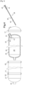
- the cryogenic tank 2 comprises an inner container 26 and an outer shell 27.
- the inner container 26 defines a storage chamber 28 of liquefied gas for containing a load of gas at liquefaction temperature and a canopy of evaporated gas.
- the inner container 26 is sealed.
- the inner container 26 is capable of withstanding a liquefaction temperature, for example -253°C for hydrogen.
- the outer casing 27 contains the inner container 26.
- the outer casing 27 is made of several removable parts allowing access to the inner container 26.
- the outer casing 27 protects the inner container 26 against impacts.
- the outer casing 27 ensures the structural strength of the aeronautical gas storage device.
- the outer casing 27 is made of a material resistant to temperatures from less than -60°C to at least +80°C.
- an insulation chamber 29 is defined between the inner container 26 and the outer shell 27, an insulation chamber 29 is defined.
- the insulation in the insulation chamber 29 is provided by a pressure reduced compared to atmospheric pressure.
- a solid insulating material may be disposed in the insulation chamber 29.
- the reduced pressure insulation chamber 29 having a helium tightness equal to or better than 10 -9 millibar*liter/second is defined between the inner container 26 and the outer shell 27.
- the tightness of the insulation chamber 29 includes the tightness with respect to the interior of the inner container 26 and the tightness with respect to the outside atmosphere.
- the inner container 26 may be made of a welded metal alloy.
- An example of a metal alloy may be Al-Cu-Li, in particular 2050 or 2099, Al-Cu, in particular 2219, stainless steel, in particular 304, 304L, 316, 316L.
- the inner container 26 has an elongated shape with two curved ends surrounding a body.
- the body may be cylindrical.
- the body may be of revolution.
- the outer casing 27 comprises a frame 30, sealed panels 31, pressure-resistant seals between the frame 30 and the panels 31 and/or between the panels 31.
- the panels 31 can be assembled to the frame 30 by screwing.
- the chassis 30 comprises members 32 and side members 33.
- the members 32 may have a closed contour, for example annular.
- the side members 33 extend longitudinally.
- the side members 33 meet at the ends of the outer casing 27.
- the panels 31 are made of welded metal alloy or composite materials.
- composite materials may be epoxy resin with carbon fibers, Kevlar fibers and/or glass fibers.
- An example of a metal alloy may be Al-Mg, especially 5086, Al-Mg-Si, especially 6061, Al-Cu-Li, especially 2195.
- seals Between the panels 31 and the frame 30 are provided seals.
- the seals may be metal/metal or made of synthetic material, for example elastomer.
- grooves are provided in the panels 31 or in the frame 30 to accommodate said seals. In the free state, the seals protrude from the grooves by a height less than 10% of a height of said seals. Height means the diameter for an O-ring.
- the cryogenic tank 2 includes two connections between the outer shell 27 and the inner container 26 for supporting the inner container 26.
- the connections are configured for very low thermal conduction.
- At least one of the connections is sliding to accommodate the differential expansion of the outer casing 27 and the inner container 26.
- the connections are carried by the outer casing 27.
- a first of the connections is extreme.
- the extreme connection 34 may comprise a central projection at one end of the inner container 26 cooperating with an axial concavity of the outer casing 27 forming a housing for the protuberance with axial sliding over a stroke of a few millimeters so that the contraction of the inner container 26 upon filling with a liquefied gas and the expansion of the inner container 26 after emptying of the liquefied gas is free.
- the extreme connection 34 is configured to have a long thermal conduction path.
- the second connection is located at a distance from the opposite end to the first connection.
- the second connection surrounds the inner container 26.
- the second connection is mounted in the insulation chamber 29.
- the second connection includes a support ring 35.
- the support ring 35 is mounted between the inner container 26 and the outer casing 27.
- the support ring 35 is mounted at a distance from the connections in the insulation chamber 29.
- the support ring 35 comprises external sectors 36 projecting radially outwards.
- the external sectors 36 are three in number here.
- the external sectors 36 have a peripheral surface in contact with the bore of the outer casing 27.
- the external sectors 36 occupy an angle of the order of 15 to 40°.
- the support ring 35 comprises internal sectors 37 projecting radially inwards.
- the internal sectors 37 are here three in number.
- the internal sectors 37 have a convex surface in contact with the periphery of the inner container 26.
- the internal sectors 37 occupy an angle of the order of 15 to 40°.
- the external sectors 36 and the internal sectors 37 are alternated.
- the external sectors 36 and the internal sectors 37 are angularly distant from each other.
- three internal sectors 37 and three external sectors 36 of approximately 20 to 30° are alternately distributed and separated by zones devoid of projection and occupying an angle of approximately 40 to 30° respectively.
- the support ring 35 is held by sufficient friction against the inner container 26 or by permanent fixing.
- the support ring 35 is made of composite material with low thermal conductivity and high mechanical strength.
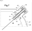
- the cryogenic tank 2 comprises a removable collector 38 passing through the outer casing 27 and the inner container 26 in a sealed manner.
- the collector 38 comprises a straight pipe 39 for sampling liquefied gas from the inner container 26.
- the pipe 39 is made of insulating material.
- the collector 38 comprises a first end open inside the inner container 26.
- the collector 38 comprises a second end open outside the outer casing 27.
- the second end is intended to be connected to a pipe, for example an outlet pipe 4, cf. Figure 6 .
- the first and second ends are connected by a port.
- the first end, in the assembled state, is located near the bottom of the inner container 26.
- the first end is free.
- the manifold 38 draws off liquefied gas. Drawing off is stopped when the liquid level is low.
- the inner container 26, in operation contains a gas phase and a liquid phase.
- the liquid phase is at a maximum and the gas phase is at a minimum.
- the liquid phase is at a minimum, or even absent, and the gas phase is at a maximum.
- the liquid phase is drawn off. Drawing off the liquid phase relative to the gas phase allows for lines of significantly smaller diameter. The compactness of the components downstream of the cryogenic tank 2 is improved.
- the pipe 39 is also used for filling with liquefied gas.
- the collector 38 comprises, on the second end side, a buffer 41 surrounding the rod 39.
- the buffer 41 is made of insulating material.
- the buffer 41 projects outside the outer casing 27.
- the buffer 41 may have a gripping area for disassembly, for example during maintenance.
- the buffer 41 has an outside diameter greater than the diameter of the rod 39.
- the buffer 41 forms a removable sealed head of the cryogenic tank 2.
- a cap assembly includes the cap pad 41 and a cap cover 45.
- the cryogenic tank 2 may be mounted with the cap assembly facing the front of the device and the free end of the rod 39 toward the rear of the device to take advantage of the general inclination of the device of a few degrees allowing a more complete filling with liquefied gas and a more complete withdrawal of the liquefied gas.
- the cryogenic tank 2 may also be mounted inclined, in particular by means of a support member of unequal height between the front and the rear of the cryogenic tank 2.
- the collector 38 includes a liquid level gauge 40.
- the gauge 40 extends along the rod 39.
- the gauge 40 is connected to the outside of the tank by wired communication passing through the buffer 41.
- the gauge 40 provides an output signal representative of the liquid level.
- the gauge may be capacitive.
- the accuracy of the gauge is higher when the collector 38 has a small angle relative to the horizontal. Indeed, for a given resolution of the gauge and a given height of the inner container 26, an increased length of the inner container 26 allows an increased length of the gauge therefore increased precision. For example, a gauge at 30° to the horizontal sees its precision doubled compared to a vertical gauge.
- the manifold 38 includes a gas vent 53 for rapid discharge in the event of overpressure.
- the vent 53 is also used during filling to evacuate gases to avoid overpressure.
- the vent 53 is used during withdrawal for repressurization by introducing gas if necessary.
- the vent 53 is arranged in the buffer 41 and opens into the inner container 26 near the buffer 41.
- the vent 53 is provided with a liquid non-return valve.
- the vent 53 is arranged in the buffer 41 and opens into the inner container 26 near the buffer 41. Thus, the vent 53 is connected to the gaseous headspace of the inner container 26.
- the vent 53 is connected to a conduit passing through the buffer 41.
- a valve with an opening pressure lower than the pressure admissible by the cryogenic tank 2 can be connected to the conduit.
- a rupture disk with a rupture pressure lower than the pressure admissible by the cryogenic tank 2 can be connected to the conduit. The valve and the rupture disk are mounted in parallel.
- the collector 38 comprises a temperature sensor disposed in the bottom of the buffer 41 on the inner side.
- the temperature sensor provides temperature information measured in the inner container 26.
- the cryogenic tank 2 comprises a thermally insulating neck 42.
- the neck 42 has a bore.
- the neck 42 may be made of metal.
- the metal is chosen to be a low thermal conductor, mechanically strong, flexible and hydrogen-tight.
- the neck 42 is welded or screwed with a seal to the inner container 26.
- the neck 42 is welded or screwed with a seal to the outer casing 27.
- the neck 42 is sufficiently flexible to accommodate differences in expansion between the inner container 26 and the outer casing 27.
- the neck 42 comprises an outer wall attached to the inner container 26 and the outer casing 27.
- the neck 42 comprises an inner wall spaced from the inner container 26 and the outer casing 27.
- the inner wall may be attached to the outer wall at the ends of the neck 42.
- the outer wall is tubular.
- the inner wall is tubular in the form of a bellows.
- the inner wall may be made of sheet metal with a thickness less than the sheet metal of the outer wall to increase elastic deformability.
- the inner wall may have a bellows shape which increases the ability to elastically deform.
- a bellows shape for example corrugated, reduces the contact surface between the inner wall and the pad 41, resulting in low thermal conduction.
- the inner bellows wall comprises two concentric sheets. Said sheets are fitted into each other and connected at the ends. This forms a double wall allowing to reduce the risk of leakage.
- detection can be carried out by applying a gas pressure between the two sheets higher than the pressure in the insulation chamber and lower than atmospheric pressure and by monitoring the evolution of the applied pressure. If said applied pressure decreases, the large diameter sheet has a leak with the insulation chamber. If said applied pressure increases, the small diameter sheet has a leak with the bore of the neck 42. The neck can then be changed.
- the insulation chamber maintains its low pressure ensuring low thermal conduction and the cryogenic tank 2 is operational until the next maintenance operation. In the case of a single sheet losing its seal, the insulation chamber loses its low thermal conduction property and the cryogenic tank 2 is urgently emptied with loss of its contents.
- the neck 42 forms a sealed interface between the collector 38 on the one hand and the outer casing 27 and the inner container 26 on the other hand.
- the neck 42 maintains the gas-tightness between the outer casing 27 and the inner container 26, regardless of the position of the collector 38, or even its absence.
- the neck 42 is fixed in a sealed manner in a bore provided in the outer casing 27.
- the neck 42 is fixed in a sealed manner in a bore provided in the inner container 26.
- the bore in the outer casing 27 and the bore in the inner container 26 are provided at one of the rounded ends of the cryogenic tank 2 near the outer diameter of the cryogenic tank 2 in the upper part.
- the collector 38 extends beyond the neck 42 towards the outside by an external end.
- the manifold 38 extends beyond the neck 42 into the cryogenic tank 2 downwardly and toward the other of the rounded ends of the cryogenic tank 2.
- the neck 42 is arranged around a portion of the collector 38.
- the neck 42 passes through the isolation chamber 29 to allow disassembly of the collector 38 independent of the pressure in the isolation chamber 29.
- the neck 42 is provided with a through hole 43 in which the buffer 41 of the collector 38 is installed in a removable manner.
- the contact surface between the neck 42 and the buffer 41 may be provided with a female annular toothing 44 to increase the length of a leak path and promote the mechanical retention of the collector 38 in the neck.
- the toothing 44 has chevrons.
- the buffer 41 has, in the free state, a smooth outer surface of revolution.
- the buffer 41 is adapted to the neck 42. A slight clearance between the bellows and the buffer 41 may be provided.
- a liquid deflector is provided inside the neck near the storage chamber 28.
- the pad 41 is made of thermally insulating material.
- the pad 41 may include a resilient shell and an insulating synthetic foam in the shell.
- the neck 42 is welded to the inner container 26 around its outer wall.
- the neck 42 has a flange superimposed on a flange of the inner container 26.
- the welding can be carried out by electron beam directed towards the flanges.
- the neck 42 is welded to the outer casing 27 around its outer wall at a distance from the weld to the inner container 26.
- the outer wall of the neck 42 comprises two distinct and separate parts, one connected to the inner container 26, and the other connected to the outer casing 27.
- the inner wall connects the two parts of the outer wall.
- the inner wall comprises two concentric sheets with a thickness of between 0.1 and 0.2 mm.
- the neck 42 comprises a flange 54 directed towards the inner wall.
- the flange 54 connects the inner wall and the outer wall in a sealed manner.
- a seal 55 is fixed to the flange 54, in particular by screwing. The seal 55 comes into contact with the buffer 41 of the collector 38.
- the level gauge is absent.
- the cryogenic tank 2 comprises a cover 45 permanently mounted on the collector 38 and accessible from the outside.
- the cover 45 is fixed to the rod 39 by screws or bolts.
- the cover 45 is arranged outside the outer casing 27.
- the cover 45 is arranged at said outer end of the collector 38.
- the cover 45 is sealed.
- Cryogenic tank 2 is designed for a working pressure of less than 8 bars, in particular 6 bars.
- the cryogenic tank 2 comprises an anti-sway member installed inside the inner container 26.
- the anti-sway member comprises one or more perforated panels separating the inner volume of the inner container 26 into several zones.
- the openings of the perforated panels may have a surface area of the order of 1 to 5% of the surface area of the perforated panels.
- the perforated panels may be longitudinal or transverse. The perforated panels reduce the speed of movement of the liquefied gas in the inner container 26 during acceleration, for example during takeoff, landing or during atmospheric turbulence.
- the cryogenic tank 2 comprises a stiffener inside the inner container 26.
- the stiffener comprises at least one spacer or tie rod connecting opposite regions of the inner container 26. The stiffener makes it possible to lighten the rest of the structure of the inner container 26.
- a hydrogen adsorbent material 46 for example a nanoporous material, is installed in the isolation chamber 29 .
- the loss of insulation linked to the increase in pressure in the isolation chamber 29 is reduced.
- the outer casing 27 is dismantled to open the isolation chamber 29 and the hydrogen adsorbent material 46 is removed to desorb the hydrogen, for example by heating.
- a hydrogen presence detector 47 is installed in the isolation chamber 29. The presence of hydrogen is monitored. In the event of a large leak, emergency emptying of the inner container 26 can be ordered. In the event of a small leak, a maintenance operation can be anticipated. The operation of maintenance may include repairing the inner container 26 to remedy the leak, replacing or desorbing the hydrogen adsorbent material, if applicable, and re-evacuating the isolation chamber 29.
- the outer casing 27 comprises two separable parts 48 and 49.
- a first part 48 comprises an end and a body.
- a second part 49 comprises an opposite end.
- the first and second parts are connected in a sealed and separable manner by two sealing rings 50 and 51 providing metal/metal sealing surfaces by interference.
- the interference can be cone on cone, torus on cone, or plane on plane with, if necessary, a hot-mounted metal O-ring - in particular made of copper alloy - or of elastomer.
- the interference is ensured by axial tightening, in particular by bolts.
- the sealing rings 50 and 51 are annular.
- the outer casing 27 is made in several sections. Two sections are connected in a sealed manner by sealing rings 50 and 51 as described above. Sections can be standardized for different capacities of inner container 26 with an end section, one or more central sections, and an end section provided with the bore for the neck. Several support rings 35 can be provided.
- the frame 30 of the outer casing 27 comprises annular members 32, side members 33 parallel to the longitudinal axis and diagonal braces.
- the outer casing 27 comprises panels 31 of generally triangular shape, each mounted between a member, a side member and a brace, and curved panels at the ends.
- the triangular panels 31 leave the frame 30 exposed.
- the curved panels cover the frame 30 beyond the members 32.
- the distribution circuit 1 comprises a first valve 11 for each cryogenic tank 2.
- the first valve 11 is mounted on the outlet pipe 4.
- the first valves 11 are controlled with an open position and a closed position.
- the intermediate positions of the first valves 11 are dynamic in the sense that the first valves 11 are in motion while passing through said intermediate positions. In other words, the first valves 11 are all or nothing.
- the first valves 11 can be arranged immediately downstream of the flow meters 22.
- the first valves 11 open into a cryogenic distributor 5.
- the cryogenic distributor 5 may comprise a common pipe 6 connecting the outlets of the first valves 11.
- the distributor is cryogenic in the sense that it sees liquid fuel/oxidant pass through it.
- each second valve 12 Downstream of each second valve 12 is mounted a central tank 7.
- Three central tanks 7 are provided in this embodiment. Each central tank 7 also serves as a gasifier. Insulation can be avoided. Each central tank 7 receives liquid and supplies gas downstream. A pressure increase or gasification step occurs in each central tank 7 between filling and emptying. Each central tank 7 is capable of withstanding a maximum operating pressure of the order of 300 to 1000 bars. Each central tank 7 is designed to operate in a temperature range from -253°C to +60°C. The central tanks 7 are two-phase for part of the operating steps and single-phase gas for the other operating steps. Each central tank 7 can be equipped with a heating member 8.
- each central tank 7 Downstream of each central tank 7 is installed a third valve 13 to supply gas and a pressure reducer 9 downstream of the third valve 13.
- the pressure reducer 9 limits the pressure to supply gas at a consumption pressure set by the manufacturer of the consumer member 3.
- the pressure reducer 9 is active when the pressure in the central tank 7 is higher than the consumption pressure and inactive otherwise.
- the consumption pressure is lower than the maximum pressure of the central tank 7.
- the consumption pressure is independent of the maximum pressure of the cryogenic tanks.
- the third valves 13 are all or nothing.
- a fourth controlled valve 14 Downstream of each regulator 9, a fourth controlled valve 14 can be provided.
- the fourth valves 14 are all or nothing.
- the manifold 10 may comprise a pipe connecting the outlets of the fourth valves 14 or the regulators 9.
- the manifold 10 sees gas pass through.
- the manifold 10 is connected downstream to supply pipes 23 to the consumer members 3.
- a supply pipe 23 is provided for each consumer member 3.
- Each supply pipe 23 may be equipped with a controlled supply valve 24.
- the supply valve 24 has a variable flow rate.
- the distribution circuit 1 comprises at least one compressor 20 connected to the manifold 10.
- the compressor 20 is electric.
- the compressor 20 may be equipped with a controlled upstream valve.
- the compressor 20 delivers gas into the collector 10.
- the collector 10 consists of a pipe in the case of a single consumer organ 3.
- each central tank 7 Downstream of each central tank 7 is installed a fifth valve 15 to supply gas and a second manifold 38 downstream of the fifth valves 15.
- the second manifold 38 is connected to the compressor 20.
- the fifth valves 15 make it possible to isolate the central tanks 7 and the compressor 20.
- the fifth valves 15 are controlled.
- the fifth valves 15 are all or nothing.
- the compressor 20 increases the pressure to supply gas at a pressure equal to a consumption pressure set by the manufacturer of the consumer member 3.
- the consumption pressure is lower than the maximum pressure in the central tank 7.
- the compressor 20 makes it possible to take gas from a central tank 7 whose pressure is lower than the consumption pressure to supply the collector 10 and the consumer members 3.
- a more complete emptying of the central tank 7 makes it possible to increase the autonomy provided by the gas contained in a central tank 7 or to reduce the volume of the central tank 7.
- the distribution circuit 1 offers a combination of individual states of each cryogenic tank, each central tank 7 and each consumer member 3.
- Several consumer members 3 can be active simultaneously. In normal mode, one cryogenic tank is being emptied while the others are inactive and therefore closed. However, in certain situations, for example to reduce the pressure in several cryogenic tanks, a particular mode can be provided in which several cryogenic tanks are being emptied.
- the central tanks 7 have a filling mode, a gasification mode, a gas storage mode and an emptying mode.
- the corresponding first valve 11 When one of the cryogenic tanks is being emptied, the corresponding first valve 11 is open and the other first valves 11 are closed. When one of the consumer members 3 is being supplied, the corresponding supply valve 24 is open.
- the second valve 12 connected to said central tank 7 is open and at least one of the first valves 11 is open.
- the others second valves 12 are closed except in the case where simultaneous filling of two central tanks 7 is carried out.
- the third valve 13 connected to said central tank 7 is closed.
- the fifth valve connected to said central tank 7 is closed.
- the gasification mode is of short duration, in particular in the case of a warm ambient atmosphere and/or heating of the central tank 7.
- the second valve 12 connected to said central tank 7 When one of the central tanks 7 is in draining mode, the second valve 12 connected to said central tank 7 is closed. In the first part of draining, the pressure in the central tank 7 is higher than the consumption pressure.
- the third valve 13 connected to said central tank 7 is open, the corresponding fourth valve 14 is open and the fifth valve connected to said central tank 7 is closed.
- the gas undergoes a pressure reduction in the pressure reducer 9 and is supplied to the manifold 10 at the consumption pressure. The gas is then consumed by the consumer member(s) 3.
- a flow meter 22 is arranged at the outlet of each source of liquid fuel/oxidant 2.
- the flow meters 22 make it possible to know with sufficient precision the quantity of liquid supplied to such central tank 7.
- the distribution circuit 1 comprises a control unit 25 receiving an external instruction, for example from the consumer members 3 external to the aeronautical storage device or from a central control unit of the aircraft, and liquid flow rate data from the flow meters 22.
- the control unit 25 generates and sends instructions to said first, second, third, fourth and fifth controlled valves and to the controlled supply valves 24.
- the instructions can be "open” or "closed”.
- the control unit 25 manages said combination of individual states.
- the first valves 11 may be replaced by at least one multi-way valve having several inlets and one outlet.
- a multi-way valve with mixed positions, in particular at least one position for simultaneously emptying two or more cryogenic tanks 2 to reduce the pressure while avoiding loss into the atmosphere.
- the second valves 12 can be replaced by at least one multi-way valve having an inlet and several outlets, one per central reservoir 7. Said multi-way valve forms a distributor.
- the regulators 9 are replaced by a single regulator 9, the third valves 13 opening into the single regulator 9.
- the third valves 13 can be replaced by at least one multi-way valve having several inlets and one outlet to the regulator.
- the fourth valves 14 are then replaced by a single fourth valve 14, possibly not piloted.
- the fifth valves 15 can be replaced by at least one multi-way valve having several inlets, one per central tank 7, and an outlet to the compressor 20 or compressors 20.
- Said multi-way valve forms a manifold 10.
- a gas collection circuit may be provided in an upper portion of the cryogenic tanks 2.
- the collection circuit may be activated above a threshold pressure by a calibrated pressure valve.
- the collection circuit comprises a compressor for re-injecting the gas downstream, for example between the fifth valves 15 and the compressor 20.
- additional flow meters are placed at the inlet of each buffer tank. Redundancy of liquid flow measurement is ensured.
- the capacity of the cryogenic tank device is between 10 kg and 10000 kg of gas, preferably between 100 kg and 10000 kg of gas.
- a temporary storage and gasification tank 7 is provided for increasing the pressure of the gas supplied by the device.
- An upstream valve 12 is provided to be open for liquid flow during a filling phase of the temporary storage tank 7 and closed outside the filling phase.
- At least one downstream valve 13, 15 is provided to be open for gas flow during a draining phase of the temporary storage tank 7 and closed outside the draining phase.
- the upstream valve and the downstream valve are closed during a gasification phase.
- the upstream valve and the downstream valve are controlled in all or nothing mode.
- At least one compressor 20 is arranged downstream of the downstream valve 15.
- the compressor 20 is active at the end of the draining phase to bring the pressure in the temporary storage tank 7 to a value lower than the value of the pressure in the device.
- a pressure reducer 9 is arranged downstream of the downstream valve.
- the regulator 9 is active at the start of the emptying phase to bring the outlet gas pressure to a value lower than the pressure in the temporary storage tank 7.
- the device for a railway, road or maritime cryogenic gas storage tank comprises an inner container defining a storage chamber 28 for liquefied gas, an outer casing 27 containing the inner container and made of several removable parts allowing access to the inner container, the outer casing 27 being made of a material resistant to temperatures of less than -60°C to at least +80°C, an insulation chamber 29 defined between the inner container and the outer casing, the reduced pressure insulation chamber 29 having a helium seal equal to or better than 10 -9 millibar*liter/second defined between the inner container and the outer casing, two connections, at least one of which is sliding, supporting the inner container and carried by the outer casing, a support ring mounted between the inner container and the outer casing at a distance from the connections in the insulation chamber, a removable collector 38 passing through the outer casing and the container interior in a sealed manner, and a flexible thermally insulating neck 42 forming a sealed interface between the collector
- the storage and distribution assembly comprises a cryogenic hydrogen storage tank device, comprising an inner container defining a liquefied gas storage chamber, an outer casing containing the inner container, a sealed insulation chamber defined between the inner container and the outer casing, a removable liquefied gas collector passing through the outer casing and the inner container in a sealed manner, the collector extending over a diameter or a diagonal of the inner container and having a free end close to a bottom of the inner container, a liquefied gas pipe supplied by the collector, a temporary storage tank forming a gasification member for increasing the pressure of the gas supplied by the device, an upstream valve designed to be open for liquid flow during a filling phase of the temporary storage tank and closed outside the filling phase, a downstream valve designed to be open for gas flow during a draining phase of the temporary storage tank and closed outside the draining phase, the upstream valve and the downstream valve being closed during a gasification, the upstream valve and the downstream valve being controlled in all or nothing mode, and a pressure regulator arranged downstream of the
Landscapes
- Engineering & Computer Science (AREA)
- Mechanical Engineering (AREA)
- General Engineering & Computer Science (AREA)
- Physics & Mathematics (AREA)
- Thermal Sciences (AREA)
- Filling Or Discharging Of Gas Storage Vessels (AREA)
Description
- La présente invention concerne le domaine de l'aéronautique.
- Depuis ses débuts, l'aéronautique a utilisé des moteurs à essence à haut indice d'octane. Après 1945, le développement du réacteur et de la turbine a conduit à l'utilisation du kérosène, dont la masse moléculaire est plus élevée que celle de l'essence et dont l'inflammabilité est inférieure. Le stockage de ces carburants est effectué dans des réservoirs situés dans les ailes, dans la liaison fuselage-aile ou dans la queue.
- La tendance à la réduction des émissions de gaz carbonique a conduit à des moteurs consommant moins. Toutefois les gains sur les émissions de gaz carbonique s'amenuisent au fur et à mesure de la maturité des certaines technologies, notamment la vitesse en extrémité des pales des aubes. Il est apparu de plus en plus souhaitable d'introduire une rupture.
- Ainsi sont apparus des projets d'avions à gaz. La combustion de gaz à chaîne carbonée courte ou inexistante le cas échéant avec de l'oxygène, est peu ou non polluante. Par contre, le stockage de gaz H2, O2 ou en C1 ou C2 en raison de la petite taille de la molécule de gaz est difficile et sujet à des risques de fuites.
- Au sol, la conservation de tels gaz e est en général effectuée dans des enveloppes sous pression trop lourdes, trop volumineuses et contenant trop d'énergie potentielle de pression pour être embarquées à bord d'un aéronef ou dans des réservoirs cryogéniques soudés et/ou collés. La conservation cryogénique de tels gaz est limitée à une durée limitée proportionnelle au volume stocké.
-
US10955089 B2 - Par ailleurs, l'hydrogène, le méthane, l'éthane, l'éthylène, l'acétylène ou l'oxygène stocké à l'état liquide n'est pas utilisable par un moteur à combustion interne ou externe ou une pile à combustible. La consommation finale nécessite un état gazeux.
- Le besoin est apparu de stocker du gaz de propulsion au sein d'un aéronef pour sa consommation à bord tout en mettant en œuvre les savoir-faire de maintenance aéronautique et en évitant le besoin d'une nouvelle normalisation. En effet, l'élaboration de normes nouvelles est un processus long et consommateur de temps, d'où un risque de générer des retards dans la commercialisation d'avions à gaz. L'acquisition de nouveaux savoir-faire de maintenance est également long, coûteux, voire peut susciter des réticences.
- L'invention propose un dispositif de réservoir cryogénique aéronautique, destiné à être embarqué, de stockage de gaz, de forme sphérique ou allongée, comprenant un récipient intérieur définissant une chambre de stockage de gaz liquéfié, une enveloppe extérieure contenant le récipient intérieur et réalisée en plusieurs parties démontables permettant d'accéder au récipient intérieur, l'enveloppe extérieure étant réalisée en matériau résistant à des températures de moins de -60°C à au moins +80°C, une chambre d'isolation définie entre le récipient intérieur et l'enveloppe extérieure, la chambre d'isolation à pression réduite présentant une étanchéité à l'hélium égale ou meilleure que 10-9 millibar*litre/seconde définie entre le récipient intérieur et l'enveloppe extérieure, deux liaisons dont au moins une à glissement, supportant le récipient intérieur et portées par l'enveloppe extérieure, un collecteur amovible traversant l'enveloppe extérieure et le récipient intérieur de manière étanche, et un col souple isolant thermiquement formant interface étanche entre le collecteur d'une part et d'autre part l'enveloppe extérieure et le récipient intérieur. Le col est ménagé autour d'une portion du collecteur. Le col traverse la chambre d'isolation pour permettre un démontage du collecteur indépendant de la pression dans la chambre d'isolation. Grâce à l'invention, le réservoir cryogénique répond aux exigences, notamment thermiques, aux pratiques de l'aéronautique, notamment en termes de déformation mécanique, et à l'encombrement des conduites.
- Dans un mode de réalisation, le dispositif comprend un ensemble bouchon isolant thermiquement monté de manière amovible au collecteur et accessible par l'extérieur. L'isolation thermique est satisfaisante.
- Dans un mode de réalisation, une des liaisons comprend une concavité axiale dans l'enveloppe extérieure recevant et supportant une saillie axiale du récipient intérieur. La liaison est adaptée aux dilatations susceptibles de se produire.
- Dans un mode de réalisation, l'enveloppe extérieure comprend un châssis, des panneaux étanches, des joints d'étanchéité résistant à la pression entre le châssis et les panneaux et/ou entre les panneaux. La maintenance est facilitée.
- Dans un mode de réalisation, le châssis comprend des membrures et des longerons. La construction est robuste.
- Dans un mode de réalisation, les joints d'étanchéité sont logés dans des gorges et, à l'état libre, dépassent des gorges d'une hauteur inférieure à 10% d'une hauteur desdits joints d'étanchéité. L'étanchéité est haut niveau.
- Dans un mode de réalisation, le dispositif comprend un organe anti ballant à l'intérieur du récipient intérieur. Le comportement mécanique, notamment la stabilité, du dispositif est améliorée.
- Dans un mode de réalisation, le dispositif comprend un raidisseur à l'intérieur du récipient intérieur, préférablement une entretoise ou un tirant. Le dispositif, notamment le récipient intérieur, peut être allégé.
- Dans un mode de réalisation, le dispositif comprenant au moins un anneau de support monté entre le récipient intérieur et l'enveloppe extérieure à distance des liaisons dans la chambre d'isolation. La rigidité est accrue.
- Dans un mode de réalisation, un matériau adsorbant l'hydrogène est disposé dans la chambre d'isolation. Une pression basse est maintenue dans la chambre d'isolation.
- Dans un mode de réalisation, un détecteur de présence d'hydrogène est installé dans la chambre d'isolation. Un dépassement d'une valeur limite peut faire l'objet d'une alarme.
- Dans un mode de réalisation, un ensemble comprend un dispositif comme ci-dessus, un réservoir de stockage temporaire formant un organe de gazéification pour la montée en pression du gaz alimenté par le dispositif, une vanne amont prévue pour être ouverte pour l'écoulement liquide lors d'une phase de remplissage du réservoir de stockage temporaire et fermée hors de la phase de remplissage, une vanne aval étant prévue pour être ouverte pour l'écoulement gazeux lors d'une phase de vidange du réservoir de stockage temporaire et fermée hors de la phase de vidange, la vanne amont et la vanne aval étant fermées lors d'une phase de gazéification, la vanne amont et la vanne aval étant commandées en tout ou rien, et un compresseur disposé en aval de la vanne aval, ledit compresseur étant actif en fin de phase de vidange pour amener la pression dans le réservoir de stockage temporaire à une valeur inférieure à la valeur de la pression dans le dispositif, et un détendeur disposé en aval de la vanne aval, ledit détendeur étant actif en début de phase de vidange pour amener la pression du gaz en sortie à une valeur inférieure à la pression dans le réservoir de stockage temporaire. Le dispositif assure à l'aéronef, par le volume contenu dans le ou les réservoirs temporaires, une autonomie nécessaire indépendamment de l'état du dispositif. Les réservoirs temporaires peuvent être prévus pour une pression de gaz de plusieurs centaines de bars, une pression de gaz choisie étant néanmoins fournie aux organes consommateurs. Les vannes sont fiables. Le réservoir temporaire peut être vidé suffisamment de façon à accroître la quantité de gaz disponible pour les organes consommateurs et amener le réservoir temporaire à une pression en fin de vidange inférieure à la pression courante dans le dispositif. Le remplissage du réservoir temporaire est effectué par manœuvre de vanne cryogénique sous l'effet de la différence de pression. Se passer d'une pompe cryogénique permet un gain de masse et une réduction du risque d'incident.
- Dans un mode de réalisation, le réservoir de stockage temporaire est prévu pour une pression de service supérieure à 500 bars.
- Dans un mode de réalisation, le dispositif est prévu pour une pression de service inférieure à 8 bars.
- D'autres caractéristiques et avantages de l'invention apparaîtront à l'examen de la description détaillée ci-après, et des dessins annexés, sur lesquels :
- [
Fig.1 ] illustre de façon schématique en coupe axiale un dispositif selon un aspect de l'invention. - [
Fig.2 ] illustre de façon schématique en coupe transversale un dispositif selon un aspect de l'invention. - [
Fig.3 ] illustre de façon schématique en vue de côté un dispositif démonté selon un aspect de l'invention. - [
Fig.4 ] illustre de façon schématique en vue de côté un dispositif démonté selon un autre aspect de l'invention. - [
Fig.5 ] illustre de façon schématique en perspective un dispositif selon un autre aspect de l'invention. - [
Fig.6 ] illustre de façon schématique en coupe un col selon un aspect de l'invention. - [
Fig.7 ] illustre de façon schématique en coupe un col et un collecteur selon un aspect de l'invention. - [
Fig.8 ] illustre de façon schématique en perspective un ensemble selon un aspect de l'invention. - Les dessins annexés pourront non seulement servir à compléter l'invention, mais aussi contribuer à sa définition, le cas échéant.
- Le dispositif aéronautique de stockage de gaz est conçu pour être emporté par un aéronef : avion, drone, hélicoptère, etc.. Le dispositif aéronautique de stockage de gaz contient du liquide et fournit du gaz. En d'autres termes, le gaz est stocké à très basse température sous forme liquide dans un réservoir cryogénique. Un réservoir cryogénique est inapte à résister à des pressions élevées, notamment supérieures à 10 bars.
- Le gaz stocké est choisi parmi hydrogène, méthane, éthane, éthylène, acétylène et oxygène.
- La Demanderesse entend aussi prendre en compte que la gazéification est un phénomène rapide même dans une atmosphère ambiante à -55°C rencontrée en altitude. A titre de mode de réalisation, l'hydrogène gazeux à 0°C et 1 atmosphère est de masse volumique environ 800 fois plus faible que l'hydrogène liquide à -253°C, donc de volume environ 800 fois plus élevé.
- Or les règles de maintenance aéronautique imposent de pouvoir démonter et réparer ou remplacer la plupart des pièces de l'avion. Ainsi, un aéronef est capable de se poser en un lieu quelconque - aérodrome pour un avion, aire de pose pour un hélicoptère - adapté à sa masse et à ses exigences pour l'atterrissage mais non pourvu d'équipements de maintenance spécifiques au modèle de l'aéronef. En cas d'avarie détectée, l'aéronef est configuré pour être réparé, de manière pérenne ou provisoire, ou démonté de façon à remplacer ou à réparer un composant défectueux, conformément aux manuels et documents du constructeur agréés par les autorités de sécurité aérienne. Il est souhaitable que le composant soit aisément accessible par un opérateur de maintenance. En cas de remplacement, il est souhaitable que le composant soit le plus petit possible pour une manutention et un acheminement aisé. En cas de réparation, il est souhaitable que le composant soit réparable par des outils et des procédés éprouvés et courants dans le domaine aéronautique.
- Un aéronef fait l'objet de visites d'inspection journalières, hebdomadaires, etc, immobilisant l'aéronef pour une durée à l'inverse de la fréquence.
- Or les réservoirs de gaz du domaine industriel terrestre ou du domaine spatial ne sont pas soumis à de tels exigences, notamment ne sont pas conçus pour une telle réparabilité.
- La Demanderesse a identifié un besoin de stockage, notamment d'hydrogène, de méthane, d'éthane, d'éthylène, d'acétylène ou d'oxygène, à partir de réservoirs cryogéniques aéronautiques portés par l'aéronef.
- La Demanderesse a identifié un besoin de réservoirs cryogéniques aéronautiques démontables, inspectables selon les modes d'inspection des aéronefs et réparables. En outre, on cherche un réservoir dont le rapport volume utile/volume extérieur soit élevé, dont le rapport masse de gaz contenu/masse totale soit élevé, de haute fiabilité et de haute sécurité.
- Comme illustré sur les figures, le dispositif aéronautique de stockage de gaz présente une forme générale allongée avec des extrémités arrondies. Le dispositif aéronautique de stockage de gaz peut être de forme annulaire autour d'un axe longitudinal. Le dispositif aéronautique de stockage de gaz comprend une enveloppe extérieure et un récipient intérieur. Le récipient intérieur forme une chambre de stockage de gaz liquide. Le récipient intérieur est contenu dans l'enveloppe extérieure. De manière générale, le récipient intérieur et l'enveloppe extérieure sont distants l'un de l'autre.
- Dans le mode de réalisation représenté, le dispositif aéronautique de stockage de gaz présente une partie centrale cylindrique de révolution et des extrémités hémisphériques. Toutefois, des formes présentant des exceptions à la cylindricité, à l'annularité et/ou à l'hémisphéricité peut être fabriquées.
- Chaque réservoir cryogénique est isolé pour contenir du carburant ou comburant liquide à -253°C. Chaque réservoir cryogénique est capable de résister à une pression maximale de service de l'ordre de 6 à 10 bars.
- Dans le mode de réalisation illustré sur les
figures 1 à 3 , le réservoir cryogénique 2 présente une forme allongée, notamment autour d'un axe. Le réservoir cryogénique 2 présente des extrémités bombées et une partie centrale globalement cylindrique de révolution. En variante, le réservoir cryogénique 2 présente une forme sphérique. - Le réservoir cryogénique 2 comprend un récipient intérieur 26 et une enveloppe extérieure 27. Le récipient intérieur 26 définit une chambre de stockage 28 de gaz liquéfié pour contenir un chargement de gaz à température de liquéfaction et un ciel de gaz évaporé. Le récipient intérieur 26 est étanche. Le récipient intérieur 26 est capable de supporter une température de liquéfaction, par exemple -253°C pour l'hydrogène. L'enveloppe extérieure 27 contient le récipient intérieur 26. L'enveloppe extérieure 27 est réalisée en plusieurs parties démontables permettant d'accéder au récipient intérieur 26. L'enveloppe extérieure 27 protège le récipient intérieur 26 contre les chocs. L'enveloppe extérieure 27 assure la tenue structurelle du dispositif aéronautique de stockage de gaz. L'enveloppe extérieure 27 est réalisée en matériau résistant à des températures de moins de -60°C à au moins +80°C.
- Entre le récipient intérieur 26 et l'enveloppe extérieure 27, est définie une chambre d'isolation 29. L'isolation dans la chambre d'isolation 29 est assurée par une pression réduite par rapport à la pression atmosphérique. En outre, une matière isolante solide peut être disposée dans la chambre d'isolation 29. La chambre d'isolation 29 à pression réduite présentant une étanchéité à l'hélium égale ou meilleure que 10-9 millibar*litre/seconde définie entre le récipient intérieur 26 et l'enveloppe extérieure 27. L'étanchéité de la chambre d'isolation 29 englobe l'étanchéité vis-à-vis de l'intérieur du récipient intérieur 26 et l'étanchéité vis-à-vis de l'atmosphère extérieure.
- Le récipient intérieur 26 peut être réalisé en alliage métallique soudé. Un exemple d'alliage métallique peut être Al-Cu-Li notamment 2050 ou 2099, Al-Cu notamment 2219, inox notamment 304, 304L, 316, 316L. Le récipient intérieur 26 présente une forme allongée avec deux extrémités bombées entourant un corps. Le corps peut être cylindrique. Le corps peut être de révolution.
- L'enveloppe extérieure 27 comprend un châssis 30, des panneaux 31 étanches, des joints d'étanchéité résistant à la pression entre le châssis 30 et les panneaux 31 et/ou entre les panneaux 31. Les panneaux 31 peuvent être assemblés au châssis 30 par vissage.
- Le châssis 30 comprend des membrures 32 et des longerons 33. Les membrures 32 peuvent présenter un contour fermé, par exemple annulaire. Les longerons 33 s'étendent longitudinalement. Les longerons 33 se rejoignent aux extrémités de l'enveloppe extérieure 27.
- Les panneaux 31 sont réalisés en alliage métallique soudé ou en matériaux composites. Un exemple de matériaux composites peut être de la résine époxy avec des fibres de carbone, des fibres de kevlar et/ou des fibres de verre. Un exemple d'alliage métallique peut être Al-Mg notamment 5086, Al-Mg-Si, notamment 6061, Al-Cu-Li notamment 2195.
- Entre les panneaux 31 et le châssis 30 sont prévus des joints d'étanchéité. Les joints d'étanchéité peuvent être métal/métal ou en matériau synthétique, par exemple en élastomère. Dans le cas de joints d'étanchéité en matériau synthétique, des gorges sont ménagées dans les panneaux 31 ou dans le châssis 30 pour loger lesdits joints d'étanchéité. A l'état libre, les joints d'étanchéité dépassent des gorges d'une hauteur inférieure à 10% d'une hauteur desdits joints d'étanchéité. On entend par hauteur le diamètre pour un joint torique.
- Le réservoir cryogénique 2 comprend deux liaisons entre l'enveloppe extérieure 27 et le récipient intérieur 26 pour supporter le récipient intérieur 26. Les liaisons sont configurées pour une conduction thermique très faible.
- Au moins une des liaisons est à glissement permettant d'accommoder la dilatation différentielle de l'enveloppe extérieure 27 et du récipient intérieur 26. Les liaisons sont portées par l'enveloppe extérieure 27. Une première des liaisons est extrêmale. La liaison extrêmale 34 peut comprendre une saillie centrale à une extrémité du récipient intérieur 26 venant coopérer avec une concavité axiale de l'enveloppe extérieure 27 formant logement pour la protubérance avec glissement axial sur une course de quelques millimètres de manière que la contraction du récipient intérieur 26 au remplissage par un gaz liquéfié et la dilatation du récipient intérieur 26 après vidange du gaz liquéfié soit libre. La liaison extrêmale 34 est configurée pour présenter un chemin de conduction thermique de longueur élevée.
- La deuxième liaison est située à distance de l'extrémité opposée à la première liaison. La deuxième liaison entoure le récipient intérieur 26. La deuxième liaison est montée dans la chambre d'isolation 29. La deuxième liaison comprend un anneau de support 35. L'anneau de support 35 est monté entre le récipient intérieur 26 et l'enveloppe extérieure 27. L'anneau de support 35 est monté à distance des liaisons dans la chambre d'isolation 29.
- L'anneau de support 35 comprend des secteurs externes 36 en saille radiale vers l'extérieur. Les secteurs externes 36 sont ici au nombre de trois. Les secteurs externes 36 présentent une surface périphérique en contact avec l'alésage de l'enveloppe extérieure 27. Les secteurs externes 36 occupent un angle de l'ordre de 15 à 40°.
- L'anneau de support 35 comprend des secteurs internes 37 en saille radiale vers l'intérieur. Les secteurs internes 37 sont ici au nombre de trois. Les secteurs internes 37 présentent une surface convexe en contact avec la périphérie du récipient intérieur 26. Les secteurs internes 37 occupent un angle de l'ordre de 15 à 40°. Les secteurs externes 36 et les secteurs internes 37 sont alternés. Les secteurs externes 36 et les secteurs internes 37 sont angulairement distants les uns des autres. De manière préférée, trois secteurs internes 37 et trois secteurs externes 36 d'environ 20 à 30° sont alternativement répartis et séparés par des zones dépourvues de saillie et occupant un angle d'environ 40 à 30° respectivement. L'anneau de support 35 est maintenu par un frottement suffisant contre le récipient intérieur 26 ou par fixation à demeure.
- L'anneau de support 35 est réalisé en matériau composite à faible conduction thermique et à haute résistance mécanique.
- Le réservoir cryogénique 2 comprend un collecteur 38 amovible traversant l'enveloppe extérieure 27 et le récipient intérieur 26 de manière étanche. Le collecteur 38 comprend une canne 39 droite pour prélèvement de gaz liquéfié dans le récipient intérieur 26. La canne 39 est réalisée en matériau isolant. Le collecteur 38 comprend une première extrémité ouverte à l'intérieur du récipient intérieur 26. Le collecteur 38 comprend une deuxième extrémité ouverte à l'extérieur de l'enveloppe extérieure 27. La deuxième extrémité est prévue pour être reliée à une conduite par exemple une conduite de sortie 4, cf.
figure 6 . Les première et deuxième extrémités sont reliées par une lumière. La première extrémité, à l'état monté, est située à proximité du bas du récipient intérieur 26. La première extrémité est libre. Ainsi, le collecteur 38 soutire du gaz liquéfié. Le soutirage est arrêté lorsque le niveau de liquide est bas. En d'autres termes, le récipient intérieur 26, en fonctionnement, contient une phase gazeuse et une phase liquide. En fin de remplissage, la phase liquide est maximale et la phase gazeuse est à un minimum. En fin de soutirage, la phase liquide est à un minimum, voire absente, et la phase gazeuse est maximale. La phase liquide est soutirée. Le soutirage de la phase liquide par rapport à la phase gazeuse permet des conduites de diamètre nettement plus petit. La compacité des organes en aval du réservoir cryogénique 2 est améliorée. La canne 39 sert également au remplissage avec du gaz liquéfié. - Le collecteur 38 comprend, du côté de la deuxième extrémité, un tampon 41 entourant la canne 39. Le tampon 41 est réalisé en matériau isolant. Le tampon 41 est en saillie à l'extérieur de l'enveloppe extérieure 27. Le tampon 41 peut présenter une zone de préhension pour le démontage, par exemple en maintenance. Le tampon 41 présente un diamètre extérieur supérieur au diamètre de la canne 39. Le tampon 41 forme une tête étanche démontable du réservoir cryogénique 2.
- Un ensemble bouchon comprend le tampon 41 de bouchon et un capot 45 de bouchon. Dans le cas d'un appareil type avion ou drone, le réservoir cryogénique 2 peut être monté avec l'ensemble bouchon orienté vers l'avant de l'appareil et l'extrémité libre de la canne 39 vers l'arrière de l'appareil pour mettre à profit l'inclinaison générale de l'appareil de quelques degrés permettant un remplissage plus complet en gaz liquéfié et un soutirage plus complet du gaz liquéfié. Le réservoir cryogénique 2 peut également être monté incliné, notamment au moyen d'un organe de support de hauteur inégale entre l'avant et l'arrière du réservoir cryogénique 2.
- En outre, le collecteur 38 comprend une jauge de niveau de liquide 40. La jauge 40 s'étend le long de la canne 39. La jauge 40 est reliée à l'extérieur du réservoir par communication filaire traversant le tampon 41. La jauge 40 fournit en sortie un signal représentatif du niveau de liquide. La jauge peut être capacitive. La précision de la jauge est d'autant plus élevée que le collecteur 38 présente un angle faible par rapport à l'horizontale. En effet, pour une résolution donnée de la jauge et une hauteur donnée du récipient intérieur 26, une longueur accrue du récipient intérieur 26 permet une longueur accrue de la jauge donc une précision accrue. Par exemple, une jauge à 30° par rapport à l'horizontale voit sa précision doublée par rapport à une jauge verticale.
- Le collecteur 38 comprend un évent 53 gazeux pour une décharge rapide en cas de surpression. L'évent 53 sert aussi lors du remplissage à évacuer les gaz pour éviter une surpression. L'évent 53 sert lors du soutirage pour une remise en pression par introduction gaz si besoin. L'évent 53 est disposé dans le tampon 41 et débouche dans le récipient intérieur 26 à proximité du tampon 41. L'évent 53 est muni d'un clapet anti retour de liquide.
- L'évent 53 est disposé dans le tampon 41 et débouche dans le récipient intérieur 26 à proximité du tampon 41. Ainsi l'évent 53 est relié au ciel gazeux du récipient intérieur 26. L'évent 53 est relié à un conduit traversant le tampon 41. Une soupape à pression d'ouverture inférieure à la pression admissible par le réservoir cryogénique 2 peut être reliée au conduit. Un disque de rupture à pression de rupture inférieure à la pression admissible par le réservoir cryogénique 2 peut être relié au conduit. La soupape et le disque de rupture sont montés en parallèle.
- Le collecteur 38 comprend un capteur de température disposé dans le bas du tampon 41 du côté intérieur. Le capteur de température fournit une information de température mesurée dans le récipient intérieur 26.
- Le réservoir cryogénique 2 comprend un col 42 isolant thermiquement. Le col 42 présente un alésage. Le col 42 peut être réalisé en métal. Le métal est choisi pour être peu conducteur thermiquement, résistant mécaniquement, souple et étanche à l'hydrogène. Le col 42 est soudé ou vissé avec joint d'étanchéité au récipient intérieur 26. Le col 42 est soudé ou vissé avec joint d'étanchéité à l'enveloppe extérieure 27. Le col 42 est suffisamment souple pour accommoder des différences de dilation entre le récipient intérieur 26 et l'enveloppe extérieure 27. Le col 42 comprend une paroi extérieure fixée au récipient intérieur 26 et à l'enveloppe extérieure 27. Le col 42 comprend une paroi intérieure distante du récipient intérieur 26 et de l'enveloppe extérieure 27. La paroi intérieure peut être fixée à la paroi extérieure aux extrémités du col 42.
- La paroi extérieure est tubulaire. La paroi intérieure est tubulaire en forme de soufflet. La paroi intérieure peut être réalisée en tôle métallique d'épaisseur inférieure à la tôle métallique de la paroi extérieure pour augmenter la déformabilité élastique. La paroi intérieure peut présenter une forme de soufflet laquelle accroît l'aptitude à la déformation élastique. Une forme de soufflet, par exemple onduleux, diminue la surface de contact entre la paroi intérieure et le tampon 41, d'où une conduction thermique faible.
- Avantageusement, la paroi intérieure à soufflet comprend deux tôles concentriques. Lesdites tôles sont emboîtées l'une dans l'autre et reliées en extrémités. On forme ainsi une double paroi permettant de diminuer le risque de fuite. En cas de percement de l'une des deux tôles, une détection peut être effectuée en appliquant entre les deux tôles une pression de gaz supérieure à la pression dans la chambre d'isolation et inférieure à la pression atmosphérique et en surveillant l'évolution de la pression appliquée. Si ladite pression appliquée diminue, la tôle de grand diamètre présente une fuite avec la chambre d'isolation. Si ladite pression appliquée augmente, la tôle de petit diamètre présente une fuite avec l'alésage du col 42. Le col peut alors être changé. De plus, si seulement l'une des tôles présente une fuite, la chambre d'isolation conserve sa pression basse assurant la faible conduction thermique et le réservoir cryogénique 2 est opérationnel jusqu'à la prochaine opération de maintenance. Dans le cas d'une tôle unique perdant son étanchéité, la chambre d'isolation perd sa propriété de faible conduction thermique et le réservoir cryogénique 2 est vidangé en urgence avec perte de son contenu.
- Le col 42 forme un interface étanche entre le collecteur 38 d'une part et d'autre part l'enveloppe extérieure 27 et le récipient intérieur 26. Le col 42 maintient l'étanchéité au gaz entre l'enveloppe extérieure 27 et le récipient intérieur 26, quelle que soit la position du collecteur 38, voire son absence. Le col 42 est fixé de manière étanche dans un perçage ménagé dans l'enveloppe extérieure 27. Le col 42 est fixé de manière étanche dans un perçage ménagé dans le récipient intérieur 26. Le perçage dans l'enveloppe extérieure 27 et le perçage dans le récipient intérieur 26 sont prévus à l'une des extrémités arrondies du réservoir cryogénique 2 à proximité du diamètre extérieur du réservoir cryogénique 2 en partie haute. Le collecteur 38 s'étend au-delà du col 42 vers l'extérieur par une extrémité externe. Le collecteur 38 s'étend au-delà du col 42 vers l'intérieur du réservoir cryogénique 2 vers le bas et vers l'autre des extrémités arrondies du réservoir cryogénique 2.
- Le col 42 est ménagé autour d'une portion du collecteur 38. Le col 42 traverse la chambre d'isolation 29 pour permettre un démontage du collecteur 38 indépendant de la pression dans la chambre d'isolation 29. Le col 42 est prévu avec un trou 43 traversant dans lequel est installé le tampon 41 du collecteur 38 de manière démontable. La surface de contact entre le col 42 et le tampon 41 peut être prévue avec une denture 44 annulaire femelle pour augmenter la longueur d'un chemin de fuite et favoriser la tenue mécanique du collecteur 38 dans le col. Ici, la denture 44 présente des chevrons. Le tampon 41 présente à l'état libre une surface extérieure lisse de révolution. Le tampon 41 est adapté au col 42. Un léger jeu entre le soufflet et le tampon 41 peut être prévu. Un déflecteur de liquide est prévu à l'intérieur du col à proximité de la chambre de stockage 28. Le tampon 41 est réalisé en matériau isolant thermiquement. Le tampon 41 peut comprendre une coque résistante et une mousse synthétique isolante dans la coque.
- Dans le mode de réalisation des
figures 6 et7 , le col 42 est soudé au récipient intérieur 26 autour de sa paroi extérieure. Le col 42 présente une bride superposée à une bride du récipient intérieur 26. La soudure peut être effectuée par faisceau d'électrons dirigé vers les brides. Le col 42 est soudé à l'enveloppe extérieure 27 autour de sa paroi extérieure à distance de la soudure au récipient intérieur 26. La paroi extérieure du col 42 comprend deux parties distinctes et séparées l'une reliée au récipient intérieur 26, et l'autre reliée à l'enveloppe extérieure 27. - La paroi intérieure relie les deux parties de la paroi extérieure. La paroi intérieure comprend deux tôles concentriques d'épaisseur comprise entre 0,1 et 0,2 mm. Vers l'extérieur, le col 42 comprend une collerette 54 dirigée vers la paroi intérieure. La collerette 54 relie de manière étanche la paroi intérieure et la paroi extérieure. Un joint d'étanchéité 55 est fixé à la collerette 54, notamment par vissage. Le joint d'étanchéité 55 vient en contact avec le tampon 41 du collecteur 38. Ici, la jauge de niveau est absente.
- Le réservoir cryogénique 2 comprend un capot 45 monté à demeure au collecteur 38 et accessible par l'extérieur. Le capot 45 est fixé à la canne 39 par vis ou boulons. Le capot 45 est disposé à l'extérieur de l'enveloppe extérieure 27. Le capot 45 est disposé à ladite extrémité externe du collecteur 38. Le capot 45 est étanche.
- Le réservoir cryogénique 2 est prévu pour une pression de service inférieure à 8 bars, notamment 6 bars.
- Avantageusement, le réservoir cryogénique 2 comprend un organe anti ballant installé à l'intérieur du récipient intérieur 26. L'organe anti ballant comprend un ou plusieurs panneaux ajourés séparant le volume intérieur du récipient intérieur 26 en plusieurs zones. Les jours des panneaux ajourés peuvent présenter une surface de l'ordre de 1 à 5 % de la surface des panneaux ajourés. Les panneaux ajourés peuvent être longitudinaux ou transversaux. Les panneaux ajourés réduisent la vitesse de déplacement du gaz liquéfié dans le récipient intérieur 26 en lors d'accélérations, par exemple au décollage, à l'atterrissage ou lors de turbulences atmosphériques.
- Avantageusement, le réservoir cryogénique 2 comprend un raidisseur à l'intérieur du récipient intérieur 26. Le raidisseur comprend au moins une entretoise ou un tirant liant des régions opposées du récipient intérieur 26. Le raidisseur permet d'alléger le reste de la structure du récipient intérieur 26.
- Dans la chambre d'isolation 29, est installé un matériau adsorbant 46 l'hydrogène, par exemple un matériau nanoporeux. En cas de fuite légère, on réduit la perte d'isolation liée à l'augmentation de pression dans la chambre d'isolation 29. Après une telle fuite, l'enveloppe extérieure 27 est démontée pour ouverture de la chambre d'isolation 29 et le matériau adsorbant 46 l'hydrogène est retiré pour désorber l'hydrogène, par exemple par chauffage.
- Un détecteur de présence d'hydrogène 47 est installé dans la chambre d'isolation 29. On surveille la présence d'hydrogène. En cas de forte fuite, on peut commander la vidange d'urgence du récipient intérieur 26. En cas de légère fuite, on peut anticiper une opération de maintenance. L'opération de maintenance peut comprendre la réparation du récipient intérieur 26 pour remédier à la fuite, le remplacement ou la désorption du matériau adsorbant l'hydrogène, le cas échéant, et la remise au vide de la chambre d'isolation 29.
- Dans le mode de réalisation illustré sur les
figures 1 à 3 , l'enveloppe extérieure 27 comprend deux parties séparables 48 et 49. Une première partie 48 comprend une extrémité et un corps. Une deuxième partie 49 comprend une extrémité opposée. La première et la deuxième parties sont reliées de manière étanche et séparable par deux bagues d'étanchéité 50 et 51 offrant des surfaces d'étanchéité métal/métal par interférence. L'interférence peut être cône sur cône, tore sur cône, ou plan sur plan avec le cas échéant un joint torique en métal monté à chaud - notamment en alliage de cuivre - ou en élastomère. L'interférence est assurée par un serrage axial, notamment par des boulons. Les bagues d'étanchéité 50 et 51 sont annulaires. - Dans le mode de réalisation illustré sur la
figure 4 , l'enveloppe extérieure 27 est réalisée en plusieurs tronçons. Deux tronçons sont reliés de manière étanche par des bagues d'étanchéité 50 et 51 comme décrit ci avant. Des tronçons peuvent être standardisés pour différentes contenances de récipient intérieur 26 avec un tronçon d'extrémité, un ou plusieurs tronçons centraux, et un tronçon d'extrémité pourvu du perçage pour le col. Plusieurs anneaux de support 35 peuvent être prévus. - Dans le mode de réalisation illustré sur la
figure 5 , le châssis 30 de l'enveloppe extérieure 27 comprend des membrures 32 annulaires, des longerons 33 parallèles à l'axe longitudinal et des entretoises diagonales. L'enveloppe extérieure 27 comprend des panneaux 31 de forme générale triangulaire, chacun monté entre une membrure, un longeron et une entretoise, et des panneaux bombés aux extrémités. Les panneaux 31 triangulaires laissent le châssis 30 apparent. Les panneaux bombés recouvrent le châssis 30 au-delà des membrures 32. - Dans le mode de réalisation illustré sur la
figure 6 , le circuit de distribution 1 comprend une première vanne 11 pour chaque réservoir cryogénique 2. La première vanne 11 est montée sur la conduite de sortie 4. Les premières vannes 11 sont pilotées avec une position ouverte et une position fermée. Les positions intermédiaires des premières vannes 11 sont dynamiques en ce sens que les premières vannes 11 sont en mouvement en passant dans lesdites positions intermédiaires. En d'autres termes, les premières vannes 11 sont tout ou rien. Les premières vannes 11 peuvent être disposées immédiatement en aval des débitmètres 22. - Les premières vannes 11 débouchent dans un distributeur cryogénique 5. Le distributeur cryogénique 5 peut comprendre une conduite commune 6 reliant les sorties des premières vannes 11. Le distributeur est cryogénique en ce sens qu'il voit passer du carburant/comburant liquide.
- Le distributeur cryogénique 5 comprend une pluralité de sorties, ici trois. Sur chacune desdites sorties sont montées des deuxièmes vannes 12. Les deuxièmes vannes 12 sont pilotées avec une position ouverte et une position fermée. Les positions intermédiaires des deuxièmes vannes 12 sont dynamiques en ce sens que les deuxièmes vannes 12 sont en mouvement en passant dans lesdites positions intermédiaires. En d'autres termes, les deuxièmes vannes 12 sont tout ou rien. Les deuxièmes vannes 12 sont ici au nombre de trois.
- En aval de chaque deuxième vanne 12 est monté un réservoir central 7. Trois réservoirs centraux 7 sont prévus dans ce mode de réalisation. Chaque réservoir central 7 sert également de gazéificateur. Une isolation peut être évitée. Chaque réservoir central 7 reçoit du liquide et fournit en aval du gaz. Une élévation de pression ou étape de gazéification se produit dans chaque réservoir central 7 entre le remplissage et la vidange. Chaque réservoir central 7 est capable de résister à une pression maximale de service de l'ordre de 300 à 1000 bars. Chaque réservoir central 7 est conçu pour fonctionner dans une plage de température allant de -253°C à +60°C. Les réservoirs centraux 7 sont biphasiques sur une partie des étapes de fonctionnement et monophasiques gazeux sur les autres étapes de fonctionnement. Chaque réservoir central 7 peut être équipé d'un organe de chauffage 8.
- En aval de chaque réservoir central 7 est installé une troisième vanne 13 pour fournir du gaz et un détendeur 9 en aval de la troisième vanne 13. Le détendeur 9 écrête la pression pour fournir du gaz à une pression de consommation fixée par le fabricant de l'organe consommateur 3. Le détendeur 9 est actif lorsque la pression dans le réservoir central 7 est supérieure à la pression de consommation et inactif autrement. La pression de consommation est inférieure à la pression maximale du réservoir central 7. La pression de consommation est indépendante de la pression maximale des réservoirs cryogéniques. Les troisièmes vannes 13 sont tout ou rien.
- En aval de chaque détendeur 9, peut être prévue une quatrième vanne 14 commandée. Les quatrièmes vannes 14 sont tout ou rien.
- Les quatrièmes vannes 14 ou les détendeurs 9, selon l'option choisie, débouchent dans un collecteur 10. Le collecteur 10 peut comprendre une conduite reliant les sorties des quatrièmes vannes 14 ou des détendeurs 9. Le collecteur 10 voit passer du gaz. Le collecteur 10 est relié vers l'aval à des conduites d'alimentation 23 vers les organes consommateurs 3. En général, une conduite d'alimentation 23 est prévue pour chaque organe consommateur 3. Chaque conduite d'alimentation 23 peut être équipée d'une vanne d'alimentation 24 pilotée. La vanne d'alimentation 24 est à débit variable.
- Le circuit de distribution 1 comprend au moins un compresseur 20 relié au collecteur 10. En général deux compresseurs 20 sont prévus en parallèle pour une redondance. Le compresseur 20 est électrique. Le compresseur 20 peut être équipé d'une vanne amont pilotée. Le compresseur 20 débite du gaz dans le collecteur 10. En particulier, le collecteur 10 est constitué d'une conduite en cas d'unique organe consommateur 3.
- En aval de chaque réservoir central 7 est installé une cinquième vanne 15 pour fournir du gaz et un deuxième collecteur 38 en aval des cinquièmes vannes 15. Le deuxième collecteur 38 est relié au compresseur 20. Les cinquièmes vannes 15 permettent d'isoler les réservoirs centraux 7 et le compresseur 20. Les cinquièmes vannes 15 sont commandées. Les cinquièmes vannes 15 sont tout ou rien.
- Le compresseur 20 augmente la pression pour fournir du gaz à une pression égale à une pression de consommation fixée par le fabricant de l'organe consommateur 3. La pression de consommation est inférieure à la pression maximale dans le réservoir central 7. Le compresseur 20 permet de prélever du gaz dans un réservoir central 7 dont la pression est inférieure à la pression de consommation pour alimenter le collecteur 10 et les organes consommateurs 3. Une vidange plus complète du réservoir central 7 permet d'augmenter l'autonomie fournie par le gaz contenu dans un réservoir central 7 ou de réduire le volume du réservoir central 7.
- Une vidange du réservoir central 7 suffisante pour amener la pression interne du réservoir central 7 à une valeur inférieure à la pression dans un des réservoirs cryogéniques permet, lors du remplissage succédant à la vidange, de transférer le liquide du réservoir cryogénique vers le réservoir central 7 par différence de pression. Ainsi, le liquide du réservoir cryogénique est aspiré par le réservoir central 7 jusqu'à l'équilibre de pression. On peut se passer de pompe cryogénique, d'où un gain de masse et d'énergie consommée.
- Le circuit de distribution 1 offre une combinaison d'états individuels de chaque réservoir cryogénique, de chaque réservoir central 7 et de chaque organe consommateur 3. Plusieurs organes consommateurs 3 peuvent être actifs simultanément. En mode normal, un réservoir cryogénique est en cours de vidange tandis que les autres sont inactifs donc fermés. Toutefois, dans certaines situations, par exemple pour diminuer la pression dans plusieurs réservoirs cryogéniques, un mode particulier peut être prévu dans lequel plusieurs réservoirs cryogéniques sont en cours de vidange. Les réservoirs centraux 7 présentent un mode de remplissage, un mode de gazéification, un mode de stockage gazeux et un mode de vidange.
- Lorsque l'un des réservoirs cryogéniques est en cours de vidange, la première vanne 11 correspondante est ouverte et les autres premières vannes 11 sont fermées. Lorsque l'un des organes consommateurs 3 est en cours d'alimentation, la vanne d'alimentation 24 correspondante est ouverte.
- Lorsque l'un des réservoirs centraux 7 est en mode de remplissage, la deuxième vanne 12 reliée audit réservoir central 7 est ouverte et au moins l'une des premières vannes 11 est ouverte. Les autres deuxièmes vannes 12 sont fermées sauf dans le cas où un remplissage simultané de deux réservoirs centraux 7 est exécuté. La troisième vanne 13 reliée audit réservoir central 7 est fermée. La cinquième vanne reliée audit réservoir central 7 est fermée.
- Lorsque l'un des réservoirs centraux 7 est en mode de gazéification, la deuxième vanne 12 reliée audit réservoir central 7, la troisième vanne 13 reliée audit réservoir central 7 et la cinquième vanne 15 reliée audit réservoir central 7 sont fermées. Le mode de gazéification est de courte durée, en particulier en cas d'atmosphère ambiante chaude et/ou de chauffage du réservoir central 7.
- Lorsque l'un des réservoirs centraux 7 est en mode de vidange, la deuxième vanne 12 reliée audit réservoir central 7 est fermée. En première partie de vidange, la pression dans le réservoir central 7 est supérieure à la pression de consommation. La troisième vanne 13 reliée audit réservoir central 7 est ouverte, la quatrième vanne 14 correspondante est ouverte et la cinquième vanne reliée audit réservoir central 7 est fermée. Le gaz subit une réduction de pression dans le détendeur 9 et est fourni au collecteur 10 à la pression de consommation. Le gaz est ensuite consommé par le ou les organes consommateurs 3.
- A un instant donné, parmi trois réservoirs centraux 7, l'un est en mode de remplissage, un autre en mode de gazéification puis stockage et le troisième en mode de vidange. Comme les modes ont des durées différentes, on peut aussi trouver deux réservoirs centraux 7 en mode de remplissage et le troisième en mode de vidange ou l'inverse. On peut aussi trouver deux réservoirs centraux 7 en mode de stockage et le troisième en mode de vidange ou l'inverse.
- Dans le mode de réalisation, un_débitmètre 22 est disposé en sortie de chaque source de carburant/comburant liquide 2. Les débitmètres 22 permettent de connaître avec une précision suffisante, la quantité de liquide fournie à tel réservoir central 7.
- Dans le mode de réalisation, le circuit de distribution 1 comprend une unité de commande 25 recevant une consigne extérieure par exemple provenant des organes consommateurs 3 extérieurs au dispositif aéronautique de stockage ou d'une unité de commande centrale de l'aéronef, et des données de débit liquide provenant des débitmètres 22. L'unité de commande 25 génère et envoie des consignes auxdites premières, deuxièmes, troisièmes, quatrièmes et cinquièmes vannes commandées et aux vannes d'alimentation 24 commandées. Les consignes peuvent être « ouvert » ou « fermé ». L'unité de commande 25 gère ladite combinaison d'états individuels.
- En variante, les premières vannes 11 peuvent être remplacées par au moins une vanne multivoies possédant plusieurs entrées et une sortie. Dans ce cas, il est intéressant de prévoir une vanne multivoies à positions mixtes, notamment au moins une position de vidange simultanée de deux ou plus réservoirs cryogéniques 2 pour en réduire la pression en évitant une perte dans l'atmosphère.
- En variante, les deuxièmes vannes 12 peuvent être remplacées par au moins une vanne multivoies possédant une entrée et plusieurs sorties, une par réservoir central 7. Ladite vanne multivoies forme un distributeur.
- En variante, les détendeurs 9 sont remplacés par un détendeur 9 unique, les troisièmes vannes 13 débouchant dans le détendeur 9 unique. Dans ce cas, les troisièmes vannes 13 peuvent être remplacées par au moins une vanne multivoies possédant plusieurs entrées et une sortie vers le détendeur. Les quatrièmes vannes 14 sont alors remplacées par une seule quatrième vanne 14, le cas échéant non pilotée.
- En variante, les cinquièmes vannes 15 peuvent être remplacées par au moins une vanne multivoies possédant plusieurs entrées, une par réservoir central 7, et une sortie vers le compresseur 20 ou les compresseurs 20. Ladite vanne multivoies forme un collecteur 10.
- Les réservoirs cryogéniques 2 étant sujet à une évaporation à partir du liquide, il peut être prévu un circuit de collecte de gaz dans une partie supérieure des réservoirs cryogéniques 2. Le circuit de collecte peut être actif au-dessus d'une pression seuil par une soupape à pression étalonnée. Le circuit de collecte comprend un compresseur pour réinjecter le gaz en aval, par exemple entre les cinquièmes vannes 15 et le compresseur 20.
- En option des débitmètres supplémentaires sont disposés en entrée de chaque réservoir tampon. Une redondance de la mesure de débit de liquide est assurée.
- La contenance du dispositif de réservoir cryogénique est comprise entre 10 kg et 10000 kg de gaz, préférablement entre 100 kg et 10000 kg de gaz.
- Un réservoir de stockage temporaire 7 et de gazéification est prévu pour la montée en pression du gaz alimenté par le dispositif. Une vanne amont 12 est prévue pour être ouverte pour l'écoulement liquide lors d'une phase de remplissage du réservoir de stockage temporaire 7 et fermée hors de la phase de remplissage. Au moins une vanne aval 13, 15 est prévue pour être ouverte pour l'écoulement gazeux lors d'une phase de vidange du réservoir de stockage temporaire 7 et fermée hors de la phase de vidange. La vanne amont et la vanne aval sont fermées lors d'une phase de gazéification. La vanne amont et la vanne aval sont commandées en tout ou rien. Au moins un compresseur 20 est disposé en aval de la vanne aval 15. Le compresseur 20 est actif en fin de phase de vidange pour amener la pression dans le réservoir de stockage temporaire 7 à une valeur inférieure à la valeur de la pression dans le dispositif. Un détendeur 9 est disposé en aval de la vanne aval. Le détendeur 9 est actif en début de phase de vidange pour amener la pression du gaz en sortie à une valeur inférieure à la pression dans le réservoir de stockage temporaire 7.
- Le dispositif de réservoir cryogénique ferroviaire, routier ou maritime de stockage de gaz, de forme sphérique ou allongée, notamment autour d'un axe longitudinal, comprend un récipient intérieur définissant une chambre de stockage 28 de gaz liquéfié, une enveloppe extérieure 27 contenant le récipient intérieur et réalisée en plusieurs parties démontables permettant d'accéder au récipient intérieur, l'enveloppe extérieure 27 étant réalisée en matériau résistant à des températures de moins de -60°C à au moins +80°C, une chambre d'isolation 29 définie entre le récipient intérieur et l'enveloppe extérieure, la chambre d'isolation 29 à pression réduite présentant une étanchéité à l'hélium égale ou meilleure que 10-9 millibar*litre/seconde définie entre le récipient intérieur et l'enveloppe extérieure, deux liaisons dont au moins une à glissement, supportant le récipient intérieur et portées par l'enveloppe extérieure, un anneau de support monté entre le récipient intérieur et l'enveloppe extérieure à distance des liaisons dans la chambre d'isolation, un collecteur 38 amovible traversant l'enveloppe extérieure et le récipient intérieur de manière étanche, et un col 42 souple isolant thermiquement formant interface étanche entre le collecteur 38 d'une part et d'autre part l'enveloppe extérieure et le récipient intérieur, le col 42 étant ménagé autour d'une portion du collecteur 38, le col 42 traversant la chambre d'isolation pour permettre un démontage du collecteur 38 indépendant de la pression dans la chambre d'isolation.
- L'ensemble de stockage et de distribution comprend un dispositif de réservoir cryogénique de stockage d'hydrogène, comprenant un récipient intérieur définissant une chambre de stockage de gaz liquéfié, une enveloppe extérieure contenant le récipient intérieur, une chambre d'isolation étanche définie entre le récipient intérieur et l'enveloppe extérieure, un collecteur de gaz liquéfié amovible traversant l'enveloppe extérieure et le récipient intérieur de manière étanche, le collecteur s'étendant sur un diamètre ou une diagonale du récipient intérieur et présentant une extrémité libre voisine d'un fond du récipient intérieur, une conduite de gaz liquéfié alimentée par le collecteur, un réservoir de stockage temporaire formant un organe de gazéification pour la montée en pression du gaz alimenté par le dispositif, une vanne amont prévue pour être ouverte pour l'écoulement liquide lors d'une phase de remplissage du réservoir de stockage temporaire et fermée hors de la phase de remplissage, une vanne aval prévue pour être ouverte pour l'écoulement gazeux lors d'une phase de vidange du réservoir de stockage temporaire et fermée hors de la phase de vidange, la vanne amont et la vanne aval étant fermées lors d'une phase de gazéification, la vanne amont et la vanne aval étant commandées en tout ou rien, et un détendeur disposé en aval de la vanne aval, ledit détendeur étant actif en début de phase de vidange pour amener la pression du gaz en sortie à une valeur inférieure à la pression dans le réservoir de stockage temporaire.]
Claims (10)
- Dispositif de réservoir cryogénique aéronautique, destiné à être embarqué, de stockage de gaz, de forme sphérique ou allongée, comprenant un récipient intérieur (26) définissant une chambre de stockage (28) de gaz liquéfié, une enveloppe extérieure (27) contenant le récipient intérieur (26), une chambre d'isolation (29) définie entre le récipient intérieur (26) et l'enveloppe extérieure (27), un collecteur (38) amovible traversant l'enveloppe extérieure (27) et le récipient intérieur (26) de manière étanche, caractérisé en ce que l'enveloppe extérieure est réalisée en plusieurs parties démontables permettant d'accéder au récipient intérieur, l'enveloppe extérieure est réalisée en matériau résistant à des températures de moins de -60°C à au moins +80°C, la chambre d'isolation est à pression réduite présentant une étanchéité à l'hélium égale ou meilleure que 10-9 millibar* litre/seconde définie entre le récipient intérieur et l'enveloppe extérieure, l'enveloppe extérieure comprend deux liaisons dont au moins une à glissement, supportant le récipient intérieur et portées par l'enveloppe extérieure, et en ce que le dispositif comprend un col (42) souple isolant thermiquement formant interface étanche entre le collecteur (38) d'une part et d'autre part l'enveloppe extérieure (27) et le récipient intérieur (26), le col (42) étant ménagé autour d'une portion du collecteur (38), le col (42) traversant la chambre d'isolation (29) pour permettre un démontage du collecteur (38) indépendant de la pression dans la chambre d'isolation (29).
- Dispositif selon la revendication 1, comprenant un ensemble bouchon isolant thermiquement monté de manière amovible au collecteur (38) et accessible par l'extérieur.
- Dispositif selon l'une des revendications précédentes, dans lequel une des liaisons comprend une concavité axiale dans l'enveloppe extérieure (27) recevant et supportant une saillie axiale du récipient intérieur (26).
- Dispositif selon l'une des revendications précédentes, dans lequel l'enveloppe extérieure (27) comprend un châssis (30), des panneaux (31) étanches, des joints d'étanchéité résistant à la pression entre le châssis (30) et les panneaux (31) et/ou entre les panneaux (31).
- Dispositif selon la revendication précédente, dans lequel le châssis (30) comprend des membrures (32) et des longerons (33).
- Dispositif selon la revendication 4 ou 5, dans lequel les joints d'étanchéité sont logés dans des gorges et, à l'état libre, dépassent des gorges d'une hauteur inférieure à 10% d'une hauteur desdits joints d'étanchéité.
- Dispositif selon l'une des revendications précédentes, comprenant un organe anti ballant à l'intérieur du récipient intérieur (26) et un raidisseur à l'intérieur du récipient intérieur (26), préférablement une entretoise ou un tirant.
- Dispositif selon l'une des revendications précédentes, comprenant au moins un anneau de support (35) monté entre le récipient intérieur (26) et l'enveloppe extérieure (27) à distance des liaisons dans la chambre d'isolation (29).
- Dispositif selon l'une des revendications précédentes, dans lequel un matériau adsorbant l'hydrogène est disposé dans la chambre d'isolation (29) et un détecteur de présence d'hydrogène est installé dans la chambre d'isolation (29).
- Ensemble comprenant un dispositif selon l'une des revendications précédentes, un réservoir de stockage temporaire (7) formant un organe de gazéification pour la montée en pression du gaz alimenté par le dispositif, une vanne amont (12) prévue pour être ouverte pour l'écoulement liquide lors d'une phase de remplissage du réservoir de stockage temporaire (7) et fermée hors de la phase de remplissage, une vanne aval (13, 15) étant prévue pour être ouverte pour l'écoulement gazeux lors d'une phase de vidange du réservoir de stockage temporaire (7) et fermée hors de la phase de vidange, la vanne amont et la vanne aval étant fermées lors d'une phase de gazéification, la vanne amont et la vanne aval étant commandées en tout ou rien, et un compresseur (20) disposé en aval de la vanne aval (15), ledit compresseur (20) étant actif en fin de phase de vidange pour amener la pression dans le réservoir de stockage temporaire (7) à une valeur inférieure à la valeur de la pression dans le dispositif, et un détendeur (9) disposé en aval de la vanne aval, ledit détendeur (9) étant actif en début de phase de vidange pour amener la pression du gaz en sortie à une valeur inférieure à la pression dans le réservoir de stockage temporaire (7).
Priority Applications (1)
| Application Number | Priority Date | Filing Date | Title |
|---|---|---|---|
| EP25183374.5A EP4596948B1 (fr) | 2022-04-14 | 2023-04-04 | Dispositif démontable de stockage de gaz liquéfié |
Applications Claiming Priority (2)
| Application Number | Priority Date | Filing Date | Title |
|---|---|---|---|
| FR2203468A FR3134614B1 (fr) | 2022-04-14 | 2022-04-14 | Dispositif aeronautique demontable de stockage de gaz liquefie |
| PCT/FR2023/050478 WO2023198977A1 (fr) | 2022-04-14 | 2023-04-04 | Dispositif aeronautique demontable de stockage de gaz liquefie |
Related Child Applications (1)
| Application Number | Title | Priority Date | Filing Date |
|---|---|---|---|
| EP25183374.5A Division EP4596948B1 (fr) | 2022-04-14 | 2023-04-04 | Dispositif démontable de stockage de gaz liquéfié |
Publications (3)
| Publication Number | Publication Date |
|---|---|
| EP4490427A1 EP4490427A1 (fr) | 2025-01-15 |
| EP4490427C0 EP4490427C0 (fr) | 2025-06-18 |
| EP4490427B1 true EP4490427B1 (fr) | 2025-06-18 |
Family
ID=82694091
Family Applications (2)
| Application Number | Title | Priority Date | Filing Date |
|---|---|---|---|
| EP25183374.5A Active EP4596948B1 (fr) | 2022-04-14 | 2023-04-04 | Dispositif démontable de stockage de gaz liquéfié |
| EP23725265.5A Active EP4490427B1 (fr) | 2022-04-14 | 2023-04-04 | Dispositif aeronautique demontable de stockage de gaz liquefie |
Family Applications Before (1)
| Application Number | Title | Priority Date | Filing Date |
|---|---|---|---|
| EP25183374.5A Active EP4596948B1 (fr) | 2022-04-14 | 2023-04-04 | Dispositif démontable de stockage de gaz liquéfié |
Country Status (6)
| Country | Link |
|---|---|
| US (1) | US20250224078A1 (fr) |
| EP (2) | EP4596948B1 (fr) |
| JP (1) | JP7691164B2 (fr) |
| CN (2) | CN121296874A (fr) |
| FR (1) | FR3134614B1 (fr) |
| WO (1) | WO2023198977A1 (fr) |
Families Citing this family (1)
| Publication number | Priority date | Publication date | Assignee | Title |
|---|---|---|---|---|
| WO2025172601A1 (fr) * | 2024-02-16 | 2025-08-21 | Linde Gmbh | Récipient de stockage et procédé |
Family Cites Families (10)
| Publication number | Priority date | Publication date | Assignee | Title |
|---|---|---|---|---|
| US5819544A (en) * | 1996-01-11 | 1998-10-13 | Andonian; Martin D. | High pressure cryogenic pumping system |
| CA2362844C (fr) * | 2001-11-30 | 2004-08-31 | Westport Research Inc. | Methode et appareil de livraison de gaz a haute pression d'une cuve de stockage cryogenique |
| CA2523732C (fr) * | 2005-11-10 | 2007-09-18 | Westport Research Inc. | Systeme et methode de livraison d'un gaz comprime a partir d'un recipient de stockage cryogenique |
| CA2527563C (fr) * | 2005-12-23 | 2007-07-03 | Westport Research Inc. | Appareil et methode pour le pompage d'un fluide cryogenique a partir d'un recipient de stockage et pour l'etablissement de diagnostic des performances de la pompe cryogenique |
| CN102635776A (zh) * | 2012-04-18 | 2012-08-15 | 宁波明欣化工机械有限责任公司 | 一种高集成绝热深冷容器 |
| CA2853324C (fr) * | 2014-06-03 | 2016-02-23 | Westport Power Inc. | Recipient de stockage cryogenique |
| WO2016112462A1 (fr) * | 2015-01-14 | 2016-07-21 | Westport Power Inc. | Système de pompe pour la distribution de fluide gazeux liquéfié |
| EP3199859B1 (fr) * | 2016-01-29 | 2021-05-26 | Cryostar SAS | Pomp submersible pour la distribution de gaz liquéfié |
| FR3077617B1 (fr) * | 2018-02-07 | 2022-08-19 | Gaztransport Et Technigaz | Installation pour le stockage et le transport d'un gaz liquefie |
| FR3094070B1 (fr) * | 2019-03-21 | 2021-10-15 | Air Liquide | Dispositif et procédé de stockage et de fourniture de carburant fluide. |
-
2022
- 2022-04-14 FR FR2203468A patent/FR3134614B1/fr active Active
-
2023
- 2023-04-04 CN CN202511382006.4A patent/CN121296874A/zh active Pending
- 2023-04-04 US US18/853,777 patent/US20250224078A1/en active Pending
- 2023-04-04 EP EP25183374.5A patent/EP4596948B1/fr active Active
- 2023-04-04 EP EP23725265.5A patent/EP4490427B1/fr active Active
- 2023-04-04 CN CN202380034134.2A patent/CN119173719B/zh active Active
- 2023-04-04 WO PCT/FR2023/050478 patent/WO2023198977A1/fr not_active Ceased
- 2023-04-04 JP JP2024560618A patent/JP7691164B2/ja active Active
Also Published As
| Publication number | Publication date |
|---|---|
| EP4596948B1 (fr) | 2026-04-22 |
| CN119173719B (zh) | 2025-10-10 |
| EP4596948A2 (fr) | 2025-08-06 |
| EP4596948A3 (fr) | 2025-11-12 |
| US20250224078A1 (en) | 2025-07-10 |
| CA3248722A1 (fr) | 2023-10-19 |
| CN121296874A (zh) | 2026-01-09 |
| EP4490427C0 (fr) | 2025-06-18 |
| CN119173719A (zh) | 2024-12-20 |
| JP2025512107A (ja) | 2025-04-16 |
| JP7691164B2 (ja) | 2025-06-11 |
| EP4490427A1 (fr) | 2025-01-15 |
| WO2023198977A1 (fr) | 2023-10-19 |
| FR3134614A1 (fr) | 2023-10-20 |
| FR3134614B1 (fr) | 2024-03-15 |
Similar Documents
| Publication | Publication Date | Title |
|---|---|---|
| EP4129827B1 (fr) | Aéronef comprenant au moins un dispositif d alimentation en hydrogène ainsi qu au moins un contenant étanche dans lequel est positionné au moins un équipement dudit dispositif d alimentation en hydrogène | |
| EP2622255B1 (fr) | Système de stockage de combustible cryogénique pour un avion | |
| EP4596948B1 (fr) | Dispositif démontable de stockage de gaz liquéfié | |
| EP3577387A1 (fr) | Agencement de réservoir de carburant dans un navire | |
| CA3248722C (fr) | Dispositif aeronautique demontable de stockage de gaz liquefie | |
| EP4490426A1 (fr) | Dispositif aeronautique de stockage de gaz liquefie a collecteur | |
| CN111322173A (zh) | 环柱形贮箱固液火箭发动机 | |
| EP4490395B1 (fr) | Dispositif aeronautique de distribution de gaz | |
| EP4490394B1 (fr) | Dispositif de reservoir cryogenique aeronautique de stockage d'hydrogene, pour emport exterieur par un aeronef | |
| EP4455021B1 (fr) | Aéronef comprenant au moins un dispositif d'alimentation en hydrogène équipé d'au moins un système d'évacuation de gaz en cas de fuite | |
| FR3153127A1 (fr) | Dispositif de reservoir tampon biphasique haute pression | |
| RU2759454C2 (ru) | Плавучая конструкция, содержащая резервуар, подходящий для хранения сжиженного горючего газа | |
| CN107013803A (zh) | 船舶及船用液化天然气加注系统 |
Legal Events
| Date | Code | Title | Description |
|---|---|---|---|
| STAA | Information on the status of an ep patent application or granted ep patent |
Free format text: STATUS: UNKNOWN |
|
| STAA | Information on the status of an ep patent application or granted ep patent |
Free format text: STATUS: THE INTERNATIONAL PUBLICATION HAS BEEN MADE |
|
| PUAI | Public reference made under article 153(3) epc to a published international application that has entered the european phase |
Free format text: ORIGINAL CODE: 0009012 |
|
| STAA | Information on the status of an ep patent application or granted ep patent |
Free format text: STATUS: REQUEST FOR EXAMINATION WAS MADE |
|
| 17P | Request for examination filed |
Effective date: 20241009 |
|
| AK | Designated contracting states |
Kind code of ref document: A1 Designated state(s): AL AT BE BG CH CY CZ DE DK EE ES FI FR GB GR HR HU IE IS IT LI LT LU LV MC ME MK MT NL NO PL PT RO RS SE SI SK SM TR |
|
| GRAP | Despatch of communication of intention to grant a patent |
Free format text: ORIGINAL CODE: EPIDOSNIGR1 |
|
| STAA | Information on the status of an ep patent application or granted ep patent |
Free format text: STATUS: GRANT OF PATENT IS INTENDED |
|
| INTG | Intention to grant announced |
Effective date: 20250117 |
|
| GRAS | Grant fee paid |
Free format text: ORIGINAL CODE: EPIDOSNIGR3 |
|
| GRAA | (expected) grant |
Free format text: ORIGINAL CODE: 0009210 |
|
| STAA | Information on the status of an ep patent application or granted ep patent |
Free format text: STATUS: THE PATENT HAS BEEN GRANTED |
|
| AK | Designated contracting states |
Kind code of ref document: B1 Designated state(s): AL AT BE BG CH CY CZ DE DK EE ES FI FR GB GR HR HU IE IS IT LI LT LU LV MC ME MK MT NL NO PL PT RO RS SE SI SK SM TR |
|
| DAV | Request for validation of the european patent (deleted) | ||
| DAX | Request for extension of the european patent (deleted) | ||
| REG | Reference to a national code |
Ref country code: GB Ref legal event code: FG4D Free format text: NOT ENGLISH |
|
| REG | Reference to a national code |
Ref country code: CH Ref legal event code: EP |
|
| REG | Reference to a national code |
Ref country code: DE Ref legal event code: R096 Ref document number: 602023004129 Country of ref document: DE |
|
| REG | Reference to a national code |
Ref country code: CH Ref legal event code: EP |
|
| REG | Reference to a national code |
Ref country code: IE Ref legal event code: FG4D Free format text: LANGUAGE OF EP DOCUMENT: FRENCH |
|
| U01 | Request for unitary effect filed |
Effective date: 20250716 |
|
| U07 | Unitary effect registered |
Designated state(s): AT BE BG DE DK EE FI FR IT LT LU LV MT NL PT RO SE SI Effective date: 20250722 |
|
| PG25 | Lapsed in a contracting state [announced via postgrant information from national office to epo] |
Ref country code: NO Free format text: LAPSE BECAUSE OF FAILURE TO SUBMIT A TRANSLATION OF THE DESCRIPTION OR TO PAY THE FEE WITHIN THE PRESCRIBED TIME-LIMIT Effective date: 20250918 Ref country code: GR Free format text: LAPSE BECAUSE OF FAILURE TO SUBMIT A TRANSLATION OF THE DESCRIPTION OR TO PAY THE FEE WITHIN THE PRESCRIBED TIME-LIMIT Effective date: 20250919 |
|
| PG25 | Lapsed in a contracting state [announced via postgrant information from national office to epo] |
Ref country code: HR Free format text: LAPSE BECAUSE OF FAILURE TO SUBMIT A TRANSLATION OF THE DESCRIPTION OR TO PAY THE FEE WITHIN THE PRESCRIBED TIME-LIMIT Effective date: 20250618 |
|
| PG25 | Lapsed in a contracting state [announced via postgrant information from national office to epo] |
Ref country code: RS Free format text: LAPSE BECAUSE OF FAILURE TO SUBMIT A TRANSLATION OF THE DESCRIPTION OR TO PAY THE FEE WITHIN THE PRESCRIBED TIME-LIMIT Effective date: 20250918 |
|
| PG25 | Lapsed in a contracting state [announced via postgrant information from national office to epo] |
Ref country code: IS Free format text: LAPSE BECAUSE OF FAILURE TO SUBMIT A TRANSLATION OF THE DESCRIPTION OR TO PAY THE FEE WITHIN THE PRESCRIBED TIME-LIMIT Effective date: 20251018 |
|
| PG25 | Lapsed in a contracting state [announced via postgrant information from national office to epo] |
Ref country code: SM Free format text: LAPSE BECAUSE OF FAILURE TO SUBMIT A TRANSLATION OF THE DESCRIPTION OR TO PAY THE FEE WITHIN THE PRESCRIBED TIME-LIMIT Effective date: 20250618 |
|
| PG25 | Lapsed in a contracting state [announced via postgrant information from national office to epo] |
Ref country code: CZ Free format text: LAPSE BECAUSE OF FAILURE TO SUBMIT A TRANSLATION OF THE DESCRIPTION OR TO PAY THE FEE WITHIN THE PRESCRIBED TIME-LIMIT Effective date: 20250618 |
|
| PG25 | Lapsed in a contracting state [announced via postgrant information from national office to epo] |
Ref country code: PL Free format text: LAPSE BECAUSE OF FAILURE TO SUBMIT A TRANSLATION OF THE DESCRIPTION OR TO PAY THE FEE WITHIN THE PRESCRIBED TIME-LIMIT Effective date: 20250618 |
|
| PG25 | Lapsed in a contracting state [announced via postgrant information from national office to epo] |
Ref country code: SK Free format text: LAPSE BECAUSE OF FAILURE TO SUBMIT A TRANSLATION OF THE DESCRIPTION OR TO PAY THE FEE WITHIN THE PRESCRIBED TIME-LIMIT Effective date: 20250618 |
|
| PG25 | Lapsed in a contracting state [announced via postgrant information from national office to epo] |
Ref country code: ES Free format text: LAPSE BECAUSE OF FAILURE TO SUBMIT A TRANSLATION OF THE DESCRIPTION OR TO PAY THE FEE WITHIN THE PRESCRIBED TIME-LIMIT Effective date: 20250618 |
|
| U20 | Renewal fee for the european patent with unitary effect paid |
Year of fee payment: 4 Effective date: 20260313 |
|
| PLBE | No opposition filed within time limit |
Free format text: ORIGINAL CODE: 0009261 |
|
| STAA | Information on the status of an ep patent application or granted ep patent |
Free format text: STATUS: NO OPPOSITION FILED WITHIN TIME LIMIT |
|
| REG | Reference to a national code |
Ref country code: CH Ref legal event code: L10 Free format text: ST27 STATUS EVENT CODE: U-0-0-L10-L00 (AS PROVIDED BY THE NATIONAL OFFICE) Effective date: 20260430 |