EP4489495A1 - Sidelink-kommunikationsverfahren, endgerätevorrichtung und netzwerkvorrichtung - Google Patents
Sidelink-kommunikationsverfahren, endgerätevorrichtung und netzwerkvorrichtung Download PDFInfo
- Publication number
- EP4489495A1 EP4489495A1 EP22938813.7A EP22938813A EP4489495A1 EP 4489495 A1 EP4489495 A1 EP 4489495A1 EP 22938813 A EP22938813 A EP 22938813A EP 4489495 A1 EP4489495 A1 EP 4489495A1
- Authority
- EP
- European Patent Office
- Prior art keywords
- interlaces
- resource pool
- interlace
- sub
- comprised
- Prior art date
- Legal status (The legal status is an assumption and is not a legal conclusion. Google has not performed a legal analysis and makes no representation as to the accuracy of the status listed.)
- Pending
Links
Images


Classifications
-
- H—ELECTRICITY
- H04—ELECTRIC COMMUNICATION TECHNIQUE
- H04W—WIRELESS COMMUNICATION NETWORKS
- H04W72/00—Local resource management
- H04W72/04—Wireless resource allocation
- H04W72/044—Wireless resource allocation based on the type of the allocated resource
-
- H—ELECTRICITY
- H04—ELECTRIC COMMUNICATION TECHNIQUE
- H04W—WIRELESS COMMUNICATION NETWORKS
- H04W72/00—Local resource management
- H04W72/20—Control channels or signalling for resource management
- H04W72/23—Control channels or signalling for resource management in the downlink direction of a wireless link, i.e. towards a terminal
-
- H—ELECTRICITY
- H04—ELECTRIC COMMUNICATION TECHNIQUE
- H04L—TRANSMISSION OF DIGITAL INFORMATION, e.g. TELEGRAPHIC COMMUNICATION
- H04L5/00—Arrangements affording multiple use of the transmission path
- H04L5/0001—Arrangements for dividing the transmission path
- H04L5/0003—Two-dimensional division
- H04L5/0005—Time-frequency
- H04L5/0007—Time-frequency the frequencies being orthogonal, e.g. OFDM(A) or DMT
- H04L5/001—Time-frequency the frequencies being orthogonal, e.g. OFDM(A) or DMT the frequencies being arranged in component carriers
-
- H—ELECTRICITY
- H04—ELECTRIC COMMUNICATION TECHNIQUE
- H04L—TRANSMISSION OF DIGITAL INFORMATION, e.g. TELEGRAPHIC COMMUNICATION
- H04L5/00—Arrangements affording multiple use of the transmission path
- H04L5/003—Arrangements for allocating sub-channels of the transmission path
- H04L5/0032—Distributed allocation, i.e. involving a plurality of allocating devices, each making partial allocation
- H04L5/0033—Distributed allocation, i.e. involving a plurality of allocating devices, each making partial allocation each allocating device acting autonomously, i.e. without negotiation with other allocating devices
-
- H—ELECTRICITY
- H04—ELECTRIC COMMUNICATION TECHNIQUE
- H04L—TRANSMISSION OF DIGITAL INFORMATION, e.g. TELEGRAPHIC COMMUNICATION
- H04L5/00—Arrangements affording multiple use of the transmission path
- H04L5/003—Arrangements for allocating sub-channels of the transmission path
- H04L5/0037—Inter-user or inter-terminal allocation
-
- H—ELECTRICITY
- H04—ELECTRIC COMMUNICATION TECHNIQUE
- H04L—TRANSMISSION OF DIGITAL INFORMATION, e.g. TELEGRAPHIC COMMUNICATION
- H04L5/00—Arrangements affording multiple use of the transmission path
- H04L5/003—Arrangements for allocating sub-channels of the transmission path
- H04L5/0053—Allocation of signalling, i.e. of overhead other than pilot signals
-
- H—ELECTRICITY
- H04—ELECTRIC COMMUNICATION TECHNIQUE
- H04L—TRANSMISSION OF DIGITAL INFORMATION, e.g. TELEGRAPHIC COMMUNICATION
- H04L5/00—Arrangements affording multiple use of the transmission path
- H04L5/0091—Signalling for the administration of the divided path, e.g. signalling of configuration information
- H04L5/0094—Indication of how sub-channels of the path are allocated
-
- H—ELECTRICITY
- H04—ELECTRIC COMMUNICATION TECHNIQUE
- H04L—TRANSMISSION OF DIGITAL INFORMATION, e.g. TELEGRAPHIC COMMUNICATION
- H04L5/00—Arrangements affording multiple use of the transmission path
- H04L5/0001—Arrangements for dividing the transmission path
- H04L5/0003—Two-dimensional division
- H04L5/0005—Time-frequency
- H04L5/0007—Time-frequency the frequencies being orthogonal, e.g. OFDM(A) or DMT
-
- H—ELECTRICITY
- H04—ELECTRIC COMMUNICATION TECHNIQUE
- H04W—WIRELESS COMMUNICATION NETWORKS
- H04W72/00—Local resource management
- H04W72/40—Resource management for direct mode communication, e.g. D2D or sidelink
Definitions
- This application relates to the field of communications technologies, and more specifically, to a sidelink communication method, a terminal device, and a network device.
- a terminal device may determine, based on a sub-channel (sub-channel) and a mapping between a sub-channel and a resource block (resource block, RB) in a resource pool, an RB occupied by sidelink communication.
- a resource block resource block
- an unlicensed spectrum may be introduced into a sidelink communication scenario.
- the foregoing manner based on a mapping between a sub-channel and an RB is not compatible to a manner of dividing frequency domain resources on the unlicensed spectrum.
- This application provides a sidelink communication method, a terminal device, and a network device. The following describes the aspects involved in this application.
- a sidelink communication method includes: obtaining, by a terminal device, first information, where the first information is used to determine one or more interlaces that are in a resource pool and correspond to a sub-channel.
- a sidelink communication method includes: generating, by a network device, first information, where the first information is used to determine one or more interlaces that are in a resource pool and correspond to a sub-channel.
- a terminal device includes: an obtaining unit, configured to obtain first information, where the first information is used to determine one or more interlaces that are in a resource pool and correspond to a sub-channel.
- a network device includes: a processing unit, configured to generate first information, where the first information is used to determine one or more interlaces that are in a resource pool and correspond to a sub-channel.
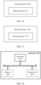
- a terminal includes a processor, a memory, and a communications interface.
- the memory is configured to store one or more computer programs
- the processor is configured to invoke the computer program in the memory, to cause the terminal device to execute some or all of the steps in the method according to the first aspect.
- a network device includes a processor, a memory, and a communications interface.
- the memory is configured to store one or more computer programs
- the processor is configured to invoke the computer program in the memory, to cause the network device to execute some or all of the steps in the method according to the second aspect.
- an embodiment of this application provides a communications system, where the system includes the foregoing terminal and/or the foregoing network device.
- the system may further include another device that interacts with the terminal or the network device in the solutions provided in embodiments of this application.
- an embodiment of this application provides a computer-readable storage medium, where the computer-readable storage medium stores a computer program, and the computer program causes a terminal to execute some or all of the steps in the method according to the first aspect.
- an embodiment of this application provides a computer-readable storage medium, where the computer-readable storage medium stores a computer program, and the computer program causes a network device to execute some or all of the steps in the method according to the second aspect.
- an embodiment of this application provides a computer program product, where the computer program product includes a non-transitory computer-readable storage medium that stores a computer program, and the computer program is operable to cause a terminal to execute some or all of the steps in the method according to the first aspect.
- the computer program product may be a software installation package.
- an embodiment of this application provides a computer program product, where the computer program product includes a non-transitory computer-readable storage medium that stores a computer program, and the computer program is operable to cause a network device to execute some or all of the steps in the method according to the second aspect.
- the computer program product may be a software installation package.
- an embodiment of this application provides a chip, where the chip includes a memory and a processor, and the processor may invoke a computer program from the memory and run the computer program, to implement some or all of the steps described in a method according to the first aspect or the second aspect.
- a terminal device may determine, based on first information, an interlace corresponding to a sub-channel, that is, establish a correspondence between a sub-channel and an interlace, which helps improve a degree of matching between sidelink communication performed based on a sub-channel and a manner of dividing resources on the unlicensed spectrum. This avoids a problem that sidelink communication based on a sub-channel does not match a division manner of an unlicensed spectrum due to that a sub-channel has a mapping with only an RB in conventional sidelink communication.
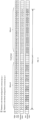
- FIG. 1 shows a wireless communications system 100 to which embodiments of this application are applicable.
- the wireless communications system 100 may include a network device 110 and terminals 121 to 129.
- the network device 110 may provide communication coverage for a specific geographic area, and may communicate with a terminal located in the coverage area.
- terminals may communicate with each other by using a sidelink (sidelink, SL).
- Sidelink communication may also be referred to as proximity services (proximity services, ProSe) communication, unilateral communication, side link communication, device-to-device (device to device, D2D) communication, or direct link communication.
- proximity services proximity services, ProSe
- D2D device to device
- sidelink data is transmitted between terminals over a sidelink.
- the sidelink data may include data and/or control signalling.
- the sidelink data may be, for example, a physical sidelink control channel (physical sidelink control channel, PSCCH), a physical sidelink shared channel (physical sidelink shared channel, PSSCH), a PSCCH demodulation reference signal (demodulation reference signal, DMRS), a PSSCH DMRS, a physical sidelink feedback channel (physical sidelink feedback channel, PSFCH), a sidelink synchronization signal block (Sidelink synchronization signal block, S-SSB), or the like.
- PSCCH physical sidelink control channel
- PSSCH physical sidelink shared channel
- DMRS demodulation reference signal
- PSSCH DMRS PSSCH DMRS
- PSFCH physical sidelink feedback channel
- S-SSB sidelink synchronization signal block
- the S-SSB includes a sidelink primary synchronization signal (sidelink primary synchronization signal, S-PSS), a sidelink secondary synchronization signal (sidelink secondary synchronization signal, S-SSS), and a physical sidelink broadcast channel (physical sidelink broadcast channel, PSBCH).
- S-PSS sidelink primary synchronization signal
- S-SSS sidelink secondary synchronization signal
- PSBCH physical sidelink broadcast channel
- Sidelink communication may be classified into three scenarios depending on whether terminals on a sidelink are located in the coverage range of the network device.
- the terminals perform sidelink communication within the coverage range of the network device.
- some of the terminals perform sidelink communication within the coverage range of the network device.
- the terminals perform sidelink communication outside the coverage range of the network device.
- terminals 121 and 122 may communicate with each other by using a sidelink, and the terminals 121 and 122 are both within the coverage range of the network device 110. In other words, the terminals 121 and 122 are both within a coverage range of a same network device 110.
- the network device 110 may transmit configuration signalling to the terminals 121 and 122, and accordingly, the terminals 121 and 122 communicate with each other by using the sidelink based on the configuration signalling.
- terminals 123 and 124 may communicate with each other by using a sidelink, the terminal 123 is within the coverage range of the network device 110, and the terminal 124 is outside the coverage range of the network device 110.
- the terminal 123 receives configuration information from the network device 110, and performs communication by using the sidelink based on a configuration of configuration signalling.
- the terminal 124 cannot receive the configuration information from the network device 110.
- the terminal 124 may obtain a configuration of sidelink communication based on pre-configured (pre-configuration) configuration information and/or configuration information transmitted by the terminal 123 within the coverage range, so that the terminal 124 communicates with the terminal 123 by using the sidelink based on the obtained configuration.
- the terminal 123 may transmit the configuration information to the terminal 124 through a sidelink broadcast channel (physical sidelink broadcast channel, PSBCH), to configure the terminal 124 to communicate by using the sidelink.
- a sidelink broadcast channel physical sidelink broadcast channel, PSBCH
- terminals 125 to 129 are all outside the coverage range of the network device 110 and cannot communicate with the network device 110.
- all the terminals may perform sidelink communication based on pre-configured information.
- the terminals 127 to 129 outside the coverage range of the network device may form a communication cluster, and the terminals 127 to 129 in the communication cluster may communicate with each other.
- the terminal 127 in the communication cluster may serve as a central control node, which is also referred to as a cluster header (cluster header, CH).
- cluster header cluster header
- the other terminals in the communication cluster may be referred to as "cluster members”.
- the terminal 127 may have one or more of the following functions: being responsible for establishment of the communication cluster; being responsible for joining and leaving of a cluster member; resource coordination, allocation of sidelink transmission resources for the cluster members, and receiving of sidelink feedback information from the cluster members; resource coordination with another communication cluster, or another function.
- FIG. 1 exemplarily shows one network device and a plurality of terminal devices.
- the wireless communications system 100 may include a plurality of network devices, and another quantity of terminal devices may be included in a coverage range of each network device. This is not limited in embodiments of this application.
- the wireless communications system 100 may further include other network entities such as a network controller and a mobility management entity. This is not limited in embodiments of this application.
- the technical solutions in embodiments of this application may be applied to various communications systems, such as a 5th generation (5th generation, 5G) system or new radio (new radio, NR), a long-term evolution (long term evolution, LTE) system, an LTE frequency division duplex (frequency division duplex, FDD) system, and LTE time division duplex (time division duplex, TDD).
- 5G 5th generation
- NR new radio
- LTE long-term evolution
- LTE frequency division duplex frequency division duplex
- FDD frequency division duplex
- TDD time division duplex
- the technical solutions provided in this application may be further applied to a future communications system, such as a sixth-generation mobile communications system or a satellite communications system.
- the terminal in embodiments of this application may also be referred to as a user equipment (user equipment, UE), an access terminal, a subscriber unit, a subscriber station, a mobile site, a mobile station (mobile station, MS), a mobile terminal (mobile terminal, MT), a remote station, a remote terminal, a mobile device, a user terminal, a terminal device, a wireless communications device, a user agent, or a user apparatus.
- the terminal device in embodiments of this application may be a device providing a user with voice and/or data connectivity and capable of connecting people, objects, and machines, such as a handheld device or a vehicle-mounted device having a wireless connection function.
- the terminal device in embodiments of this application may be a mobile phone (mobile phone), a tablet computer (Pad), a notebook computer, a palmtop computer, a mobile internet device (mobile internet device, MID), a wearable device, a virtual reality (virtual reality, VR) device, an augmented reality (augmented reality, AR) device, a wireless terminal in industrial control (industrial control), a wireless terminal in self-driving (self driving), a wireless terminal in remote medical surgery (remote medical surgery), a wireless terminal in smart grid (smart grid), a wireless terminal in transportation safety (transportation safety), a wireless terminal in smart city (smart city), a wireless terminal in smart home (smart home), or the like.
- the UE may be configured to function as a base station.
- the UE may function as a scheduling entity, which provides sidelink data between UEs in V2X, D2D, or the like.
- a cellular phone and a car communicate with each other by using sidelink data.
- a cellular phone and a smart home device communicate with each other, without relaying a communication signal by using a base station.
- the network device in embodiments of this application may be a device configured to communicate with the terminal device.
- the network device may also be referred to as an access network device or a radio access network device.
- the network device may be a base station.
- the network device in embodiments of this application may be a radio access network (radio access network, RAN) node (or device) that connects the terminal device to a wireless network.
- radio access network radio access network, RAN node (or device) that connects the terminal device to a wireless network.
- the base station may broadly cover various names in the following, or replace with the following names, for example: a NodeB (NodeB), an evolved NodeB (evolved NodeB, eNB), a next generation NodeB (next generation NodeB, gNB), a relay station, an access point, a transmitting and receiving point (transmitting and receiving point, TRP), a transmitting point (transmitting point, TP), a primary MeNB, a secondary SeNB, a multi-standard radio (MSR) node, a home base station, a network controller, an access node, a wireless node, an access point (access point, AP), a transmission node, a transceiver node, a baseband unit (base band unit, BBU), a remote radio unit (Remote Radio Unit, RRU), an active antenna unit (active antenna unit, AAU), a remote radio head (remote radio head, RRH), a central unit (central unit, CU), a distributed unit (
- the base station may be a macro base station, a micro base station, a relay node, a donor node, or the like, or a combination thereof.
- the base station may be a communications module, a modem, or a chip disposed in the device or apparatus described above.
- the base station may be a mobile switching center, a device that functions as a base station in device-to-device D2D, vehicle-to-everything (vehicle-to-everything, V2X), and machine-to-machine (machine-to-machine, M2M) communication, a network-side device in a 6G network, a device that functions as a base station in a future communications system, or the like.
- the base station may support networks of a same access technology or different access technologies. A specific technology and a specific device form used by the network device are not limited in embodiments of this application.
- the base station may be fixed or mobile.
- a helicopter or an unmanned aerial vehicle may be configured to function as a mobile base station, and one or more cells may move depending on a location of the mobile base station.
- a helicopter or an unmanned aerial vehicle may be configured to function as a device in communication with another base station.
- the network device in embodiments of this application may refer to a CU or a DU, or the network device includes a CU and a DU.
- a gNB may further include an AAU.
- the network device and the terminal device may be deployed on land, including being indoors or outdoors, handheld, or vehicle-mounted, may be deployed on a water surface, or may be deployed on a plane, a balloon, or a satellite in the air.
- a scenario in which the network device and the terminal device are located is not limited.
- a mode 1 a mode 2 a mode 3 a mode 3 a mode 3 a mode 3 a mode 3 a mode 3 a mode 3
- a network device schedules a sidelink resource for a terminal device.
- the mode 1 may include two manners: dynamic resource allocation (dynamic resource allocation) and a sidelink configured grant (sidelink configured grant, SL CG).
- dynamic resource allocation dynamic resource allocation
- sidelink configured grant sidelink configured grant
- the network device may allocate a sidelink transmission resource to the terminal by transmitting downlink control information (downlink control information, DCI).
- DCI downlink control information
- the terminal may transmit the data by using the configured sidelink resource, without re-applying for sidelink resource from the network device. Therefore, a latency of a sidelink may be reduced by the resource configuration manner of a configured grant.
- the configured grant further includes two types.
- a type 1 (Type1) of the configured grant a sidelink resource configuration is only based on radio resource control (radio resource control, RRC) signalling.
- a type 2 (Type2) of the configured grant a sidelink resource configuration in a communications system may be configured by using both RRC signalling and layer 1 (layer 1, L1) signalling, where the L1 signalling is used to indicate activation and deactivation of an RRC configuration.
- the network device may schedule, for the terminal, a sidelink resource for a single time of transmission. In some other implementations, the network device may configure a semi-persistent sidelink resource for the terminal.
- the terminal devices 121 to 123 are within the coverage range of the network device 110, and the network device 110 may allocate sidelink resources to the terminal devices 121 to 123.
- a terminal independently selects a sidelink resource from a resource pool.
- a process executed by the terminal includes a resource probing process and/or a resource selection process.
- the terminal may identify occupancy of a sidelink resource by demodulating sidelink control information (sidelink control information, SCI).
- sidelink control information SCI
- the terminal may identify occupancy of a sidelink resource by measuring a received power of a sidelink.
- the terminal devices 124 to 129 are outside the coverage range of the network device 110, and the terminal devices 124 to 129 may independently select a sidelink resource in the manner described in the mode 2.
- the autonomous driving technologies may be integrated with a communications system, or in other words, data exchange between vehicle-mounted devices may be implemented by using the communications system. Therefore, a higher requirement is imposed on the communications system. For example, the communications system is required to support higher throughput, a lower latency, higher reliability, a larger coverage range, more flexible resource allocation, and the like.
- LTE-V2X only a broadcast manner is supported for sidelink communication between terminals.
- unicast and multicast transmission manners are introduced into NR-V2X.
- a terminal 121 and a terminal 122 may communicate with each other in the unicast transmission manner.
- the terminal 121 transmits sidelink data over a sidelink
- the terminal 122 serves as a unique receiving device to receive the sidelink data.
- terminals that receive sidelink data may include all terminals in a communication cluster, or include all terminals within a specific transmission distance.
- a communication cluster including terminals 127 to 129 when the terminal 127 transmits sidelink data in a multicast manner, the other terminals 128 and 129 in the communication cluster are both receiving terminals that receive the sidelink data.
- terminals within a preset transmission distance range include the terminals 128 and 129. In this case, the terminals 128 and 129 within the preset transmission distance range are both receiving terminals that receive the sidelink data.
- a terminal that receives sidelink data may be any one of terminals around a terminal serving as a transmitting end.
- a terminal 125 serves as a transmitting end and transmits sidelink data in the broadcast manner.
- terminals 121 to 124 and terminals 126 to 129 around the terminal 125 may serve as receiving ends of the sidelink data.
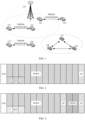
- FIG. 2 shows a frame structure of a system frame that does not carry a PSFCH in NR-V2X.
- FIG. 3 shows a frame structure of a system frame that carries a PSFCH in NR-V2X.
- a sidelink symbol occupied by a PSCCH occupies two or three sidelink symbols starting from the second sidelink symbol (for example, an orthogonal frequency division multiplexing (orthogonal frequency division multiplexing, OFDM) symbol) of a system frame.
- the PSCCH may occupy ⁇ 10, 12 15, 20, 25 ⁇ physical resource blocks (physical resource block, PRB).
- PRB physical resource block
- a quantity of PRBs occupied by the PSCCH must be less than or equal to a quantity of PRBs included in one sub-channel in the resource pool, to avoid additional limitation on resource selection or allocation of the PSSCH.
- a PSSCH in time domain, a PSSCH also starts from the second sidelink symbol of a system frame, and ends at the last but one sidelink symbol of the system frame.
- the PSSCH occupies K1 sub-channels of the system frame, where each sub-channel includes K2 consecutive PRBs, and K1 and K2 are positive integers.
- the last symbol of the system frame is a guard period (guard period, GP) symbol.
- the first sidelink symbol of the system frame is a repetition of the second sidelink symbol.
- a terminal may use the first sidelink symbol as an automatic gain control (automatic gain control, AGC) symbol.
- AGC automatic gain control
- data on the AGC symbol is not used for data demodulation.
- a sidelink symbol that is before a PSFCH sidelink symbol and carried in the system frame serves as a GP.
- An unlicensed spectrum is a spectrum that is defined by a country or a region and that may be used for communication of a radio device.
- the spectrum is generally considered as a shared spectrum, that is, communications devices in different communications systems may use the spectrum provided that a regulatory requirement set for the spectrum by the country or the region is met, and there is no need to apply for a dedicated spectrum grant from a government.
- a communications device follows a rule of "listen before talk (listen before talk, LBT)", that is, before transmitting a signal on a channel of an unlicensed spectrum, the communications device needs to perform channel listening first, and the communications device can perform signal transmission only when a result of the channel listening is that the channel is idle. If the result of the channel listening performed by the communications device on the channel of the unlicensed spectrum is that the channel is busy, the communications device cannot perform signal transmission.
- LBT listen before talk
- MCOT maximum channel occupancy time
- NR-based access to unlicensed spectrum (NR-based access to unlicensed spectrum, NR-U) is studied in a communication protocol (for example, 3GPP Rel-16).
- a communication protocol for example, 3GPP Rel-16.
- communication performed on an unlicensed band needs to meet a corresponding regulatory requirement, for example, an occupied channel bandwidth (occupied channel bandwidth, OCB) requirement and a power spectral density (power spectral density, PSD) requirement.
- occupied channel bandwidth occupied channel bandwidth
- PSD power spectral density
- An OCB is used as an example.
- European regulations stipulate that when a terminal performs data transmission by using a channel, an occupied channel bandwidth is not less than 80% of a total channel bandwidth. That is, a frequency domain span between the lowest PRB in frequency domain and the highest PRB in frequency domain occupied by the transmission of the terminal device accounts for at least 80% of a total bandwidth.
- the OCB regulation is met, if the terminal device occupies consecutive RBs in frequency domain, basically data of only one terminal device can be transmitted in one slot.
- One interlace resource includes N PRBs that are discrete in frequency domain, a total of M interlace resources are included in a band range, and PRBs included in the m th interlace are ⁇ m, M+m, 2M+m, 3M+m, ... ⁇ .
- a frequency domain spacing between two adjacent PRBs in one interlace is the same, that is, five PRBs.
- PRBs included in an interlace may also be referred to as an interlaced resource block (interlaced resource block, IRB), and the interlace may also be referred to as an IRB.
- an RB and a PRB may be replaced with each other.
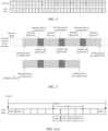
- FIG. 5 is an example of a resource pool configured on an unlicensed spectrum to which embodiments of this application are applicable.
- a resource pool is configured on an unlicensed spectrum or a shared spectrum by using pre-configuration information or network configuration information, to be used for sidelink transmission.
- the resource pool includes M1 resource block sets (resource block set, RB set), where one resource block set includes M2 resource blocks (resource block, RB), and M1 and M2 are positive integers.
- one resource block set corresponds to one channel (channel) on an unlicensed spectrum (or a shared spectrum), or one resource block set corresponds to a minimum frequency domain granularity for performing LBT, or one resource block set corresponds to an LBT sub-band.
- a bandwidth corresponding to a channel on an unlicensed spectrum is 20 MHz, that is, a bandwidth corresponding to one resource block set is also 20 MHz.
- a bandwidth of a channel on an unlicensed spectrum is 20 MHz, which corresponds to M3 RBs.
- one resource block set corresponds to a quantity of RBs included in 20 MHz.
- the resource block set may also be referred to as a channel or an LBT sub-band, which is not limited in embodiments of this application.
- a frequency domain start position of the resource pool is the same as a frequency domain start position of a first resource block set in the M1 resource block sets, where the first resource block set is a resource block set with the lowest frequency domain position in the M1 resource block sets.
- a frequency domain end position of the resource pool is the same as a frequency domain end position of a second resource block set in the M1 resource block sets, where the second resource block set is a resource block set with the highest frequency domain position in the M1 resource block sets.
- a frequency domain end position of the resource pool is the same as a frequency domain end position of the resource block set 2, or a frequency domain end position of the resource pool is determined based on a frequency domain end position of the resource block set 2.
- a guard band is included between two adjacent resource block sets in the M1 resource block sets included in the resource pool.
- a frequency domain start position and a frequency domain size of the guard band may be determined based on pre-configuration information or network configuration information.
- a terminal obtains the pre-configuration information or network configuration information, where the pre-configuration information or the network configuration information is used to configure a guard band.
- the guard band is used to separate RB sets.
- Three guard bands are configured in a sidelink BWP, and respectively correspond to a guard band 0, a guard band 1, and a guard band 2.
- the three guard bands separate four resource block sets.
- a frequency domain start position and a frequency domain end position of each resource block set may be determined based on a frequency domain start position of each guard band (that is, a starting point of the guard band shown in the figure) and a frequency domain size of the guard band (that is, a length of the guard band shown in the figure).
- a sidelink bandwidth part (bandwidth part, BWP) includes the four resource block sets, and one sidelink resource pool is configured in the sidelink BWP.
- the sidelink resource pool includes three resource block sets, that is, a resource block set 0 to a resource block set 2. Therefore, a frequency domain start position of the resource pool (that is, a starting point of a resource pool shown in the figure) corresponds to a frequency domain start position of the resource block set 0, and a frequency domain end position of the resource pool (that is, an ending point of the resource pool shown in the figure) corresponds to a frequency domain end position of the resource block set 2.
- one resource block set includes a plurality of interlaces.
- each resource block set in FIG. 5 may include a plurality of interlaces.
- one PSSCH may be transmitted in one or more resource block sets. In some other implementations, one PSSCH may be transmitted in one or more resource block sets, and the PSSCH occupies one or more interlaces in the one or more resource block sets.
- a mapping between a common resource block (common resource block, CRB) and a PRB is first described with reference to FIG. 6-A , and a mapping between a CRB and an interlace in an RB set in the NR-U system is then described with reference to FIG. 6-B .
- a CRB is equivalent to an absolute frequency domain scale that may cover one or more carrier band ranges.
- the CRB may include all RBs included in one system bandwidth.
- the CRB is numbered from 0 in frequency domain with a subcarrier spacing set to ⁇ , or in other words, a starting CRB index is CRB 0. Referring to FIG. 6-A , a CRB is numbered from a reference point in a carrier or a system bandwidth, and the reference point is referred to as a "point A".
- a subcarrier 0 of a CRB 0 is aligned with the point A.
- PRBs in the BWP are indexed from a PRB 0.
- PRBs 0 to 3 included in the BWP in the figure may correspond to any four CRBs in a carrier, that is, a frequency domain start position of the PRB 0 in the BWP may not be aligned with a CRB 0.
- FIG. 6-B shows a mapping between a CRB and an interlace in an RB set in an NR-U system.
- An uplink BWP corresponds to two RB sets. Indices of CRBs included in an RB set 0 are 2 to 25, and indices of CRBs included in an RB set 1 are 30 to 51. A guard band is configured between the two RB sets, and occupies four CRBs.
- an interlace index corresponding to an interlace is mapped by using a first-indexed CRB (a CRB 0) of a carrier as a frequency domain start position, and a mapping between an interlace index corresponding to an interlace and an index of a CRB is shown in FIG. 6-B .
- a network device when allocating an uplink transmission resource to a terminal device, a network device needs to use a two-level resource indication, that is, indicating an allocated RB set and information about an interlace in the RB set. For example, when the network device may indicate, to the terminal device, that the RB set 0 and the RB set 1 and interlaces corresponding to interlace indices 0 in the two RB sets are allocated.
- a quantity of interlaces included in one carrier is only related to a subcarrier spacing, and a correspondence between a quantity of interlaces included in a carrier and a size of a subcarrier spacing is shown in Table 1.
- a size of a subcarrier spacing is 15 kHz
- a corresponding quantity of interlaces included in a carrier is 10.
- a size of a subcarrier spacing is 30 kHz
- a corresponding quantity of interlaces included in a carrier is 5.
- a terminal device may determine, based on a sub-channel and a mapping between a sub-channel and an RB in a resource pool, an RB occupied by sidelink communication. Based on current discussion about a communication protocol, an unlicensed spectrum may be introduced into a sidelink communication scenario. As described above, to meet a related regulation (for example, the OCB) for an unlicensed spectrum, frequency domain resources on the unlicensed spectrum are divided based on an interlace.
- a related regulation for example, the OCB
- a conventional manner based on a mapping between a sub-channel and an RB is not adaptive to the unlicensed spectrum, or in other words, the conventional manner based on the mapping between a sub-channel and an RB does not match the manner of dividing frequency domain resources on the unlicensed spectrum.
- this application provides a sidelink communication method.
- FIG. 7 the following describes a flowchart of a sidelink communication method according to an embodiment of this application.
- the method shown in FIG. 7 includes step S710 and step S720.
- step S710 a terminal device obtains first information.
- the first information is used to determine an interlace that is in a resource pool and corresponds to a sub-channel, or in other words, the first information is used to indicate a correspondence between a sub-channel and an interlace in a resource pool, or in other words, the first information is used to indicate a correspondence between a sub-channel and an interlace in a sidelink BWP, or in other words, the first information is used to indicate a correspondence between a sub-channel and an interlace in a carrier.
- the foregoing correspondence may include a quantity of interlaces that are in a resource pool and included in a sub-channel.
- the first information may indicate, by using the quantity of the interlaces that are in the resource pool and included in the sub-channel, the interlaces that are in the resource pool and correspond to the sub-channel.
- the first information may indicate, by using the quantity of the interlaces that are in the resource pool and included in the sub-channel, the interlaces that are in the resource pool and correspond to the sub-channel.
- the first information may be information used for configuring a sub-channel for the terminal device, for example, may be DCI, RRC signalling, or SCI, or the first information is an information field included in DCI, RRC signalling, or SCI.
- DCI or SCI includes an information field used to indicate a frequency domain resource, and the information field corresponds to the first information.
- the information field is used to indicate information about a sub-channel of a PSSCH channel. Interlace information of the PSSCH channel may be determined based on a correspondence between the sub-channel and an interlace. Therefore, an interlace in a corresponding resource pool may be determined based on the first information.
- the first information may be a parameter that indicates a sub-channel size (sub-channel size).
- the first information may also be other information, which is not limited in embodiments of this application.
- the first information may be information in resource pool configuration information or information in sidelink BWP configuration information.
- the terminal device in step S710 may be a transmitting end of the first information, or may be a receiving end of the first information. If the terminal device is the receiving end of the first information, the first information may be transmitted by a network device, or may be transmitted by another terminal device, or may be obtained by the terminal device from pre-configuration information. That is, step S710 may include: transmitting, by another terminal device, the first information to the terminal device, or transmitting, by a network device, the first information to the terminal device. If the terminal device is the transmitting end of the first information, the first information obtained by the terminal device may be generated by the terminal device, or may be obtained by the terminal device from pre-configuration information. After obtaining the first information (that is, step S710), the terminal device may transmit the first information to another terminal device.
- the first information may be configured by a network device for the terminal device.
- the foregoing method may further include step S720, that is, the network device generates the first information.
- the terminal device may also obtain the first information in another manner, which is not limited in embodiments of this application.
- the first information may be pre-configured, for example, may be built into the terminal device before the terminal device is delivered from the factory.
- a terminal device may determine, based on first information, an interlace corresponding to a sub-channel, that is, establish a correspondence between a sub-channel and an interlace, which helps improve a degree of matching between sidelink communication performed based on a sub-channel and a manner of dividing resources on an unlicensed spectrum. This avoids a problem that sidelink communication based on a sub-channel does not match a division manner of an unlicensed spectrum due to that a sub-channel has a mapping with only an RB in conventional sidelink communication.
- one sub-channel may include one interlace. That is, an index of one sub-channel may correspond to an interlace index of one interlace, or in other words, indices of sub-channels may have a one-to-one correspondence with interlace indices of interlaces.
- an index of a sub-channel may be set to be the same as a corresponding interlace index.
- an index of a sub-channel may also be different from a corresponding interlace index.
- indices of interlaces included in a resource pool are an interlace index 0, an interlace index 1, an interlace index 2, an interlace index 3, and an interlace index 4. Since an index of a sub-channel is the same as a corresponding interlace index, indices of sub-channels include an index 0, an index 1, an index 2, an index 3, and an index 4.
- the index 0 of a sub-channel corresponds to the interlace index 0 in the resource pool
- the index 1 of a sub-channel corresponds to the interlace index 1 in the resource pool
- the index 2 of a sub-channel corresponds to the interlace index 2 in the resource pool
- the index 3 of a sub-channel corresponds to the interlace index 3 in the resource pool
- the index 4 of a sub-channel corresponds to the interlace index 4 in the resource pool.
- one channel may include a plurality of interlaces. That is, an index of one sub-channel may correspond to interlace indices of a plurality of interlaces, or in other words, indices of sub-channels may have a one-to-many correspondence with interlace indices of interlaces.
- indices of sub-channels may have a one-to-many correspondence with interlace indices of interlaces.
- a plurality of interlace indices corresponding to an index of a sub-channel may be set to be consecutive.
- a plurality of interlace indices corresponding to an index of one sub-channel may be dis-consecutive.
- the following describes a correspondence between an index of a sub-channel and an interlace index according to an embodiment of this application by using an example in which an index of one sub-channel corresponds to two consecutive interlace indices.
- indices of interlaces included in a resource pool are an interlace index 0, an interlace index 1, an interlace index 2, and an interlace index 3. Since an index of a sub-channel may correspond to two consecutive interlace indices, indices of a sub-channel include an index 0 and an index 1.
- the index 0 of the sub-channel corresponds to the interlace index 0 and the interlace index 1 in the resource pool, and the index 1 of the sub-channel corresponds to the interlace index 2 and the interlace index 3 in the resource pool.
- a total quantity of interlaces in a resource pool is an integer multiple of a maximum quantity of interlaces included in a sub-channel (the following case 1).
- a quantity of interlaces included in each sub-channel in the resource pool may be the same, that is, the maximum quantity of interlaces included in a sub-channel.
- the maximum quantity of interlaces included in a sub-channel may be the same as the quantity of the interlaces included in the sub-channel.
- a total quantity of interlaces in a resource pool is not an integer multiple of a maximum quantity of interlaces included in a sub-channel (the following case 2).
- different channels may correspond to different quantities of interlaces in the resource pool.
- interlaces included in a sub-channel may be determined based on the quantity of interlaces included in the resource pool and a quantity of interlaces included in the sub-channel.
- a quantity of interlaces included in a sub-channel may also be determined in another manner.
- a total quantity of interlaces in a resource pool is 5, and a maximum quantity of interlaces included in each sub-channel is 2.
- an index of each of two sub-channels in the resource pool may correspond to two interlace indices, and an index of the remaining one sub-channel may correspond to one interlace index.
- a difference between quantities of interlaces included in any two sub-channels in the resource pool may be set to be less than or equal to 1.
- a quantity of interlaces included in a sub-channel is not limited in embodiments of this application.
- the following describes a correspondence between an index of a sub-channel and an interlace index according to an embodiment of this application by using an example in which a maximum quantity of interlaces included in one sub-channel is 2.
- indices of interlaces included in a resource pool are an interlace index 0, an interlace index 1, an interlace index 2, an interlace index 3, and an interlace index 4, and indices of sub-channels include indices 0 to 2. Since a maximum quantity of interlaces included in a sub-channel is 2, the index 0 of a sub-channel may correspond to the interlace index 0 and the interlace index 1, the index 1 of a sub-channel may correspond to the interlace index 2 and the interlace index 3, and the index 2 of a sub-channel may correspond to the interlace index 4.
- a manner of dividing resources based on an RB set may also be introduced.
- a quantity of supported interlaces is only related to a size of a subcarrier spacing, and is not related to the quantity of the RB sets included in the uplink BWP, as shown in FIG. 6-B .
- both an RB set and an interlace resource need to be indicated, that is, a two-level resource configuration manner is used.
- a one-level resource configuration manner is currently used in a sidelink communication scenario, so that the two-level resource indication manner is not applicable to the sidelink communication scenario.
- a large quantity of transmission resources may be occupied by the two-level resource indication manner.
- an embodiment of this application provides a correspondence between an RB set and an interlace, so that a terminal device may determine, based on an interlace only, an RB set in which the interlace is located and a CRB corresponding to the interlace in the RB set. This avoids configuration of a frequency domain resource in the conventional two-level resource configuration manner, to improve a degree of matching between a resource configuration manner based on an unlicensed spectrum and a sidelink communication scenario, and reduce transmission resources occupied by the configuration of the frequency domain resource.
- a frequency domain resource occupied by sidelink communication may be indicated based on both a correspondence between an RB set and an interlace, and a correspondence between a sub-channel and an interlace (for example, any correspondence described above).
- the conventional resource configuration manner based on a sub-channel may continue to be used to configure a frequency domain resource for a terminal device.
- the terminal device may determine, based on a configured sub-channel and the foregoing two correspondences, a CRB used for sidelink communication in a resource pool.
- frequency domain resource indication information may be included in DCI or SCI.
- the frequency domain resource indication information is used to indicate a sub-channel corresponding to a PSSCH.
- An interlace resource corresponding to a frequency domain resource of the PSSCH may be determined based on a correspondence between a sub-channel and an interlace. Further, with reference to a correspondence between an RB set and an interlace, an RB set resource corresponding to the frequency domain resource of the PSSCH and an interlace resource in the RB set may be determined. Further, a physical resource corresponding to the frequency domain resource of the PSSCH may be determined based on a correspondence between the interlace resource and an RB or a CRB.
- the following describes a correspondence between an RB set and an interlace in a resource pool. It should be noted that the correspondence between an RB set and an interlace described in the following may be used in combination with any correspondence between a sub-channel and an interlace described above. This is not limited in embodiments of this application. Certainly, the correspondence between an RB set and an interlace described in the following may also be used separately.
- one RB set may include one or more interlaces. That is, an index of an RB set may correspond to one or more interlace indices, and interlaces corresponding to the one or more interlace indices belongs to the RB set.
- interlace indices corresponding to interlaces included in different RB sets in the plurality of RB sets are different.
- an RB set corresponding to an interlace index may be determined based on a correspondence between an interlace index corresponding to an interlace and an RB set.
- interlace indices corresponding to a plurality of interlaces in the resource pool may be set to be consecutively indexed across two adjacent RB sets.
- the plurality of RB sets includes a second RB set and a third RB set, an index of the second RB set is consecutive to an index of the third RB set, and interlace indices corresponding to interlaces included in the second RB are consecutive to interlace indices corresponding to interlaces included in the third RB set.
- indices corresponding to interlace resources included in the resource pool are sequentially numbered across the plurality of RB sets.
- an RB set corresponding to an interlace and an interlace resource in the RB set may be determined based on an index of the interlace.
- That the index of the second RB set is consecutive to the index of the third RB set may be implemented in many manners.
- that the index of the second RB set is consecutive to the index of the third RB set may include: the index of the second RB set and the index of the third RB set are consecutive and are incremented progressively.
- the index of the second RB set is 0, and the index of the third RB set is 1.
- that the index of the second RB set is consecutive to the index of the third RB set may include: the index of the second RB set and the index of the third RB set are consecutive and are decremented progressively.
- the index of the second RB set is 1, and the index of the third RB set is 0.
- interlace indices corresponding to interlaces included in the second RB are consecutive to interlace indices corresponding to interlaces included in the third RB set may be implemented in many manners.
- interlace indices corresponding to interlaces included in the second RB and interlace indices corresponding to interlaces included in the third RB set are consecutive and are incremented progressively.
- interlace indices corresponding to interlaces included in the second RB set are an interlace index 0 and an interlace index 1
- interlace indices corresponding to interlaces included in the third RB set are an interlace index 2 and an interlace index 3.
- interlace indices corresponding to interlaces included in the second RB and interlace indices corresponding to interlaces included in the third RB set are consecutive and are decremented progressively.
- interlace indices corresponding to interlaces included in the second RB set are an interlace index 2 and an interlace index 3
- interlace indices corresponding to interlaces included in the third RB set are an interlace index 0 and an interlace index 1.
- indices of RB sets are consecutive may be randomly combined with the manner in which interlace indices are consecutive. For example, if the index of the second RB set and the index of the third RB set are incremented progressively, the interlace indices corresponding to the interlaces included in the second RB set and the interlace indices corresponding to the interlaces included in the third RB set are incremented progressively.
- a quantity of interlaces included in each RB set in the plurality of RB sets may be the same.
- quantities of interlaces included in at least two RB sets in the plurality of RB sets may be different, which is not limited in embodiments of this application. It should be noted that in the following description of the solutions in embodiments of this application, that a quantity of interlaces included in each RB set in the plurality of RB sets is the same is used as an example.
- an interlace index corresponding to an interlace in a resource pool is determined based on an index of an RB set to which the interlace belongs, or in other words, an interlace index corresponding to an interlace included in an RB set (also referred to as a "first RB set”) is determined based on an index of the RB set.
- m 8.
- an interlace index corresponding to an interlace included in each RB set may be determined in another manner.
- the interlace index corresponding to the interlace included in each RB set may be agreed in advance by using a mapping table, which is not limited in embodiments of this application.
- interlace indices corresponding to interlaces included in different RB sets in the plurality of RB sets are the same.
- interlace indices corresponding to a plurality of interlaces in an RB set may be set to be consecutive. In other words, indices corresponding to interlace resources included in the RB set are sequentially numbered in the RB set.
- interlace indices corresponding to interlaces included in the RB set are consecutive can be implemented in many manners.
- the interlace indices corresponding to the interlaces included in the RB set are consecutive and incremented.
- the RB set includes three interlaces, and interlace indices corresponding to the three interlaces are respectively an interlace index 0, an interlace index 1, and an interlace index 2.
- the interlace indices corresponding to the interlaces included in the RB set are consecutive and decremented.
- an interlace index of an interlace corresponding to a sub-channel is referred to as a second interlace index
- an index of an interlace included in each RB set is referred to as a first interlace index.
- first interlace indices corresponding to interlaces included in a plurality of RB sets are the same.
- a resource pool includes two RB sets, which respectively correspond to an RB set 0 and an RB set 1.
- First interlace indices corresponding to interlaces included in the RB set 0 include 0 to 4, and first interlace indices corresponding to interlaces included in the RB set 1 are also 0 to 4.
- an RB set in which an interlace is located and a first interlace index of the interlace in the RB set may be determined based on a second interlace index of the interlace corresponding to an index of a sub-channel.
- a second interlace index of an interlace corresponding to a first interlace index in the RB set is determined based on an index of an RB set and the first interlace index in the RB set.
- each RB set includes M interlaces
- a first interlace index in the RB set is m 1
- a value range is 0 ⁇ m 1 ⁇ M
- m 1 is an integer greater than or equal to 0
- a second interlace index of an interlace corresponding to a sub-channel is m.
- mapping between an RB set and an interlace index in a resource pool describes a mapping between an interlace and a physical resource, where the physical resource may be represented as a PRB or a CRB.
- the physical resource may be represented as a PRB or a CRB.
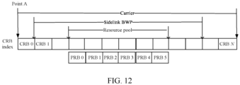
- a sidelink BWP is configured in a carrier, and a resource pool is configured in the sidelink BWP.
- An index of a PRB in the resource pool starts from a PRB 0 and CRBs are indexed from a point A.
- each of PRBs 0 to 5 in the resource pool corresponds to a respective CRB index, that is, indices of PRBs in the resource pool have correspondences with indices of CRBs in the resource pool.
- only one sidelink BWP is configured in the carrier.
- one or more resource pools may be configured in the sidelink BWP, PRBs in each resource pool are indexed from a PRB 0, and PRB indices corresponding to the PRBs in each resource pool have correspondences with CRB indices.
- mapping between an interlace and a physical resource that is, a mapping between an interlace and a CRB.
- PRBs have correspondences with CRBs in a resource pool
- the mapping between an interlace and a CRB described in the following is also applicable to a mapping between an interlace and a PRB.
- a CRB with a CRB index of x corresponds to a PRB with a PRB index of y.
- a CRB corresponding to an interlace includes the CRB x
- a resource corresponding to the interlace includes the PRB y in the resource pool, where x is an integer greater than or equal to 0, and y is an integer greater than or equal to 0.
- mapping between an interlace and a CRB may be used in combination with the correspondence between an RB set and an interlace in a resource pool described above. This is not limited in embodiments of this application.
- mapping between an interlace and a CRB may be used in combination with any correspondence between a sub-channel and an interlace described above, which is not limited in embodiments of this application.
- the mapping between an interlace and a CRB may be used in combination with any correspondence between a sub-channel and an interlace described above, and the correspondence between an RB set and an interlace in a resource pool described above. This is not limited in embodiments of this application. Certainly, in an embodiment of this application, the mapping between an interlace and a CRB may also be used separately.
- the mapping between an interlace and a CRB may be in a mapping manner 1 or a mapping manner 2.
- an interlace may be mapped by using a first frequency domain position as a frequency domain start position, where the first frequency domain position is a first-indexed CRB included in a carrier corresponding to a resource pool; or the first frequency domain position is a first-indexed CRB included in a sidelink BWP corresponding to a resource pool.
- a frequency domain start position of a first-indexed interlace in the resource pool is mapped to the first frequency domain position, and the other interlaces are mapped by using the first frequency domain position as the frequency domain start position.
- the first-indexed interlace may be an interlace with the smallest interlace index in a plurality of interlaces included in the resource pool.
- the first-indexed interlace in the resource pool may also be an interlace with the largest interlace index in the plurality of interlaces included in the resource pool.
- the other interlaces When the other interlaces are mapped, the other interlaces may be mapped in turn to CRBs corresponding to an RB set in ascending order of CRB indices in the RB set. Certainly, in this embodiment of this application, the other interlaces may also be mapped in another mapping manner.
- a correspondence between an interlace corresponding to an RB set (also referred to as a "fourth RB set") in the resource pool and a CRB may be determined based on at least one of the following: a CRB index corresponding to a frequency domain start position of the sidelink BWP, a quantity of interlaces corresponding to an RB set in the resource pool, or an interlace index corresponding to the fourth RB set.
- a correspondence between an interlace corresponding to an RB set (also referred to as a "seventh RB set") in the resource pool and a CRB may be determined based on at least one of the following: a CRB index corresponding to a frequency domain start position of a carrier, a quantity of interlaces included in an RB set in the resource pool, or an interlace index corresponding to the seventh RB set.
- S represents a quantity of RB sets included in the resource pool; s represents an index of an RB set; M represents a quantity of interlaces included in one RB set; m represents an interlace index corresponding to an interlace included in the (s + 1) th RB set; N start, ⁇ represents a CRB index corresponding to a frequency domain start position of the carrier or the sidelink BWP corresponding to the resource pool; ⁇ is determined based on a sidelink subcarrier spacing, as shown in Table 1 or Table 2; f 2 () represents a second function relationship; and m 1 is an integer greater than or equal to 0.
- n CRB Mn IRB + N start , ⁇ + m ⁇ N start , ⁇ mod M , where n IRB ⁇ ⁇ 0,1,2,3, « ⁇ , and mod() represents a modulo operation.
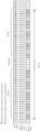
- mapping manner 1 For ease of understanding, the following continues to describe, with reference to FIG. 11 , a mapping between an interlace index corresponding to an interlace in an RB set and an index of a CRB in the RB set according to an embodiment of this application by using the mapping manner 1 as an example.
- each RB set may include five interlaces, and a resource pool includes two RB sets.
- An RB set index of the RB set 0 is 0, and CRB indices corresponding to CRBs included in the RB set 0 are 2 to 25.
- An RB set index of the RB set 1 is 1, and CRB indices corresponding to CRBs included in the RB set 1 are 30 to 51.
- CRBs corresponding to CRB indices 26 to 29 belong to a guard band. Therefore, based on the correspondence between an index of an RB set and an interlace index described above, it may be learned that interlace indices corresponding to interlaces included in the RB set 0 are interlace indices 0 to 4.
- Interlace indices corresponding to interlaces included in the RB set 1 are interlace indices 5 to 9.
- a first frequency domain position is a first-indexed CRB included in a carrier corresponding to the resource pool, that is, the first frequency domain position is a CRB corresponding to a CRB index 0, when the corresponding interlaces in the RB set 0 and the RB set 1 are mapped in the mapping manner 1, the interlaces are mapped by using the CRB corresponding to the CRB index 0 as a frequency domain start position.
- CRB indices of CRBs corresponding to an interlace with an interlace index 0 are 5, 10, 15, 20, and 25.
- CRB indices corresponding to an interlace with an interlace index 1 are 6, 11, 16, and 21.
- CRB indices corresponding to an interlace with an interlace index 2 are 2, 7, 12, 17, and 22.
- CRB indices corresponding to an interlace with an interlace index 3 are 3, 8, 13, 18, and 23.
- CRB indices corresponding to an interlace with an interlace index 4 are 4, 9, 14, 19, and 24.
- CRB indices of CRBs corresponding to an interlace with an interlace index 5 are 30, 35, 40, 45, and 50.
- CRB indices corresponding to an interlace with an interlace index 6 are 31, 36, 41, 46, and 51.
- CRB indices corresponding to an interlace with an interlace index 7 are 32, 37, 42, and 47.
- CRB indices corresponding to an interlace with an interlace index 8 are 33, 38, 43, and 48.
- CRB indices corresponding to an interlace with an interlace index 9 are 34, 39, 44, and 49.
- interlaces corresponding to the interlace index 0 and the interlace index 1 may be configured for a terminal device 1, and interlaces corresponding to the interlace indices 4 to 6 may be configured for a terminal device 2.
- FIG. 11 further shows a manner of mapping interlaces to CRBs in an NR-U system. It may be learned that a start position in the manner of mapping interlaces to CRBs in this embodiment of this application is the same as a start position in a manner of mapping interlaces to CRBs in an NR-U system.
- S represents a quantity of RB sets included in the resource pool; s represents an index of an RB set; M represents a quantity of interlaces included in one RB set; N start, ⁇ represents a CRB index corresponding to a frequency domain start position of a carrier or a sidelink BWP corresponding to the resource pool; ⁇ is determined based on a sidelink subcarrier spacing, as shown in Table 1 or Table 2; f 3 () represents a third function relationship; and m 1 is an integer greater than or equal to 0.
- an interlace is mapped by using a first-indexed CRB included in a resource pool as a frequency domain start position.
- a frequency domain start position of a first-indexed interlace is mapped to a first-indexed CRB in the resource pool, and the other interlaces in the resource pool are mapped by using the first-indexed CRB in the resource pool as the frequency domain start position.
- the first-indexed interlace may be an interlace with the smallest interlace index in a plurality of interlaces included in the resource pool.
- the first-indexed interlace may also be an interlace with the largest interlace index in the plurality of interlaces included in the resource pool.
- the first-indexed CRB in the resource pool is a CRB with the smallest CRB index in CRBs included in the resource pool.
- the first-indexed CRB in the resource pool is a CRB with the lowest frequency domain position in the resource pool.
- the other interlaces When the other interlaces are mapped, the other interlaces may be mapped in turn to CRBs corresponding to an RB set in ascending order of CRB indices in the RB set. Certainly, in this embodiment of this application, the other interlaces may also be mapped in another mapping manner.
- a correspondence between an interlace corresponding to an RB set (for example, a fifth RB set) in the resource pool and a CRB is determined based on at least one of the following: a CRB index corresponding to a frequency domain start position of an RB set, a quantity of interlaces corresponding to an RB set in the resource pool, or an interlace index corresponding to the RB set.
- the CRB index corresponding to the frequency domain start position of the RB set may be directly indicated by an index of a first CRB in the RB set, and certainly may also be determined based on a CRB index corresponding to a frequency domain start position of a sidelink BWP in the resource pool and an index of the RB set.
- S represents a quantity of RB sets included in the resource pool; s represents an index of an RB set; M represents a quantity of interlaces included in one RB set; m represents an interlace index corresponding to an interlace included in the (s + 1 ) th RB set; RB s start , u represents a CRB index corresponding to a frequency domain start position of the (s + 1) th RB set; ⁇ is determined based on a sidelink subcarrier spacing, as shown in Table 1 or Table 2; f 1 () represents a first function relationship; and m 1 is an integer greater than or equal to 0.
- a mapping between CRBs and interlaces in an RB set may be in another mapping manner.
- the interlaces may be mapped by using a last-indexed CRB in the resource pool as a frequency domain start position.
- the interlaces may also be mapped by using a first-indexed CRB or a last-indexed CRB included in the carrier corresponding to the resource pool as the frequency domain start position.
- the interlaces may also be mapped by using a last-indexed CRB included in the sidelink BWP corresponding to the resource pool as the frequency domain start position. This is not specifically limited in embodiments of this application.
- the frequency domain start positions selected in the mapping manner 1 and the mapping manner 2 are relatively simple, thereby avoiding a process of calculating a frequency domain end position.
- mapping manner 2 For ease of understanding, the following describes, with reference to FIG. 13 , a mapping between an interlace index corresponding to an interlace in an RB set and an index of a CRB in the RB set according to another embodiment of this application by using the mapping manner 2 as an example.
- each RB set may include five interlaces, and a resource pool includes two RB sets.
- An RB set index of the RB set 0 is 0, and CRB indices corresponding to CRBs included in the RB set 0 are 2 to 25.
- An RB set index of the RB set 1 is 1, and CRB indices corresponding to CRBs included in the RB set 1 are 30 to 51.
- CRBs corresponding to CRB indices 26 to 29 belong to a guard band. Therefore, based on the correspondence between an index of an RB set and an interlace index described above, it may be learned that interlace indices corresponding to interlaces included in the RB set 0 are interlace indices 0 to 4.
- Interlace indices corresponding to interlaces included in the RB set 1 are interlace indices 5 to 9.
- n CRB Mn IRB + ( m mod M ) + RB s start , ⁇ , , in the mapping manner 2, a correspondence between interlace indices corresponding to the interlaces in the RB set 0 and the RB set 1 and indices of CRBs may be calculated.
- the mapping shown in FIG. 13 may be obtained by repeating the above calculation.
- CRB indices of CRBs corresponding to an interlace with an interlace index 0 are 2, 7, 12, 17, and 22.
- CRB indices corresponding to an interlace with an interlace index 1 are 3, 8, 13, 18, and 23.
- CRB indices corresponding to an interlace with an interlace index 2 are 4, 9, 14, 19, and 24.
- CRB indices corresponding to an interlace with an interlace index 3 are 5, 10, 15, 20, and 25.
- CRB indices corresponding to an interlace with an interlace index 4 are 6, 11, 16, and 21.
- CRB indices of CRBs corresponding to an interlace with an interlace index 5 are 30, 35, 40, 45, and 50.
- CRB indices corresponding to an interlace with an interlace index 6 are 31, 36, 41, 46, and 51.
- CRB indices corresponding to an interlace with an interlace index 7 are 32, 37, 42, and 47.
- CRB indices corresponding to an interlace with an interlace index 8 are 33, 38, 43, and 48.
- CRB indices corresponding to an interlace with an interlace index 9 are 34, 39, 44, and 49.
- interlaces corresponding to the interlace index 0 and the interlace index 1 may be configured for a terminal device 1, and interlaces corresponding to the interlace indices 4 to 6 may be configured for a terminal device 2.
- FIG. 13 further shows a manner of mapping interlaces to CRBs in an NR-U system. It may be learned that a start position in the manner of mapping interlaces to CRBs in this embodiment of this application is different from a start position in a manner of mapping interlaces to CRBs in an NR-U system.
- a mapping between an index of a CRB in an RB set and an interlace index corresponding to an interlace in the RB set is established by using a first CRB included in the resource pool as a frequency domain start position, so that the mapping is more compatible with the conventional sidelink resource configuration manner.
- a correspondence between a sub-channel and an interlace may be established.
- the foregoing describes only a mapping between a sub-channel and an interlace, and the following describes a correspondence between a sub-channel and an interlace based on an RB set.
- mapping manner 2 a mapping between an interlace index corresponding to an interlace and an index of a CRB is the same as that shown in FIG. 13 . That is, the mapping is determined based on the mapping manner 2.
- the mapping is determined based on the mapping manner 2.
- the following mainly describes a correspondence between a sub-channel index and an interlace index corresponding to an interlace.
- an index of a sub-channel may be set to be the same as an interlace index of a corresponding interlace.
- an index 0 of a sub-channel corresponds to an interlace index 0
- an index 1 of a sub-channel corresponds to an interlace index 1
- an index 2 of a sub-channel corresponds to an interlace index 2
- an index 3 of a sub-channel corresponds to an interlace index 3
- an index 4 of a sub-channel corresponds to an interlace index 4.
- an index 5 of a sub-channel corresponds to an interlace index 5
- an index 6 of a sub-channel corresponds to an interlace index 6
- an index 7 of a sub-channel corresponds to an interlace index 7
- an index 8 of a sub-channel corresponds to an interlace index 8
- an index 9 of a sub-channel corresponds to an interlace index 9.
- indices of sub-channels configured for a terminal device 1 are 0 to 1
- indices of sub-channels configured for a terminal device 2 are 4 to 6.
- a correspondence between a total quantity of interlaces in a resource pool and a quantity of interlaces included in a sub-channel may include two cases, that is, a case 1 and a case 2.
- the quantity of the interlaces included in the resource pool is an integer multiple of the quantity of the interlaces included in the sub-channel.
- the quantity of the interlaces included in the resource pool is not an integer multiple of the quantity of the interlaces included in the sub-channel.
- the quantity of the interlaces included in the resource pool is equal to a product of a quantity of RB sets included in the resource pool and a quantity of interlaces included in one RB set, or the quantity of the interlaces included in the resource pool is equal to a sum of quantities of interlaces included in all RB sets included in the resource pool.
- a quantity of interlaces included in each RB set in the resource pool is an integer multiple of the quantity of the interlaces included in the sub-channel.
- a quantity of interlaces included in each RB set in the resource pool is not an integer multiple of the quantity of the interlaces included in the sub-channel.
- a quantity of interlaces included in each sub-channel in the resource pool may be the same, that is, a maximum quantity of interlaces included in a sub-channel.
- the maximum quantity of interlaces included in a sub-channel may be the same as the quantity of the interlaces included in the sub-channel.
- a quantity of interlaces included in an RB set may be set to an integer multiple of a quantity of interlaces included in a sub-channel, or in other words, a terminal expects that a quantity of interlaces included in one RB set in the resource pool is an integer multiple of a quantity of interlaces included in a sub-channel (that is, a size of the sub-channel), or in other words, a terminal does not expect that a quantity of interlaces included in one RB set in the resource pool is not an integer multiple of a quantity of interlaces included in a sub-channel (that is, a size of the sub-channel).
- a quantity of interlaces included in all RB sets in the resource pool may be set to integer multiples of a quantity of interlaces included in a sub-channel, or in other words, a terminal expects that the quantity of interlaces included in all RB sets in the resource pool is integer multiples of a quantity of interlaces included in a sub-channel (that is, a size of the sub-channel), or in other words, a terminal does not expect that the quantity of interlaces included in all RB sets in the resource pool is not integer multiples of a quantity of interlaces included in a sub-channel (that is, a size of the sub-channel).
- the case 4 is similar to the case 2 described above.
- a quantity of interlaces included in each sub-channel in one RB set may be different.
- an interlace included in a sub-channel may be determined based on a quantity of interlaces included in an RB set (also referred to as a "sixth RB set") and the quantity of the interlaces included in the sub-channel.
- a quantity of interlaces included in a sub-channel may also be determined in another manner.
- a difference between quantities of interlaces included in any two sub-channels in the RB set may be set to be less than or equal to 1.
- a quantity of interlaces included in a sub-channel in an RB set is not limited in embodiments of this application.
- the following describes a method for determining an interlace corresponding to a sub-channel in the case 4 and the case 2 based on a scenario in which resources are divided by using an RB set.
- an interlace corresponding to a sub-channel in an RB set may be determined based on one or more of the following parameters: a quantity of interlaces included in the RB set, or a quantity of interlaces included in the sub-channel.
- the quantity of the interlaces included in the RB set is represented as M
- the quantity of the interlaces included in the sub-channel is represented as N.
- (K1-R1) sub-channels may include [floor(M/N)] interlace resources, and the remaining R1 sub-channels may include [floor(M/N)-1] interlace resources, where ceil() represents a ceiling operation, floor() represents a flooring operation, and mod() represents a modulo operation.
- each of two sub-channels in the RB set (the RB set 0 or the RB set 1) may include two interlace resources, and the remaining one sub-channel may include one interlace resource.
- K 1 ceil(M/N)
- each sub-channel in (K1 *N-M) sub-channels in the RB set includes (N-1) interlace resources, having a total of A interlace resources.
- A (K1*N-M)*(N-1).
- Each sub-channel in the remaining (M-A)/N sub-channels includes N interlace resources.
- each sub-channel in two sub-channels includes two interlace resources, having a total of four interlace resources.
- Each sub-channel in the remaining two sub-channels includes three interlace resources.
- the (K1*N-M) sub-channels that each includes (N-1) interlace resources may be the first (K1*N-M) sub-channels in the RB set, or the (K1*N-M) sub-channels that each includes (N-1) interlace resources may be the last (K1*N-M) sub-channels in the RB set. This is not limited in embodiments of this application.
- a difference between quantities of interlaces included in any two sub-channels in the RB set may be set to be less than or equal to 1, thereby improving evenness of resource division.
- a total quantity of interlaces included in a resource pool may be understood as a total quantity of interlaces included in all RB sets in the resource pool.
- the case 2 may be expressed as that the quantity of the interlaces included in all the RB sets in the resource pool is not an integer multiple of the quantity of the interlaces included in the sub-channel.
- an interlace corresponding to a sub-channel in an RB set may be determined based on one or more of the following parameters: a quantity of interlaces included in the RB set, a quantity of interlaces included in the sub-channel, or a quantity of the RB sets included in the resource pool.
- the quantity of the interlaces included in the RB set is represented as M
- the quantity of the interlaces included in the sub-channel is represented as N
- the quantity of the RB sets included in the resource pool is S.
- (K2-R2) sub-channels may include [floor(S ⁇ M/N)] interlace resources, and the remaining R2 sub-channels may include [floor(S ⁇ M/N)-1] interlace resources, where ceil() represents a ceiling operation, floor() represents a flooring operation, and mod() represents a modulo operation.
- each of two sub-channels in all the RB sets in the resource pool may include two interlace resources, and the remaining one sub-channel may include one interlace resource.
- K2 ceil(S ⁇ M/N)
- each sub-channel in (K2*N-M) sub-channels in all the RB sets in the resource pool includes (N-1) interlace resources, having a total of A interlace resources
- A (K2*N-M)*(N-1).
- Each sub-channel in the remaining (K2*M-A)/N sub-channels includes N interlace resources, where ceil() represents a ceiling operation.
- each sub-channel in two sub-channels includes two interlace resources, having a total of four interlace resources.
- Each sub-channel in the remaining two sub-channels includes three interlace resources.
- the (K2*N-M) sub-channels that each includes (N-1) interlace resources may be the first (K2*N-M) sub-channels in the RB set, or the (K2*N-M) sub-channels that each includes (N-1) interlace resources may be the last (K2*N-M) sub-channels in the RB set. This is not limited in embodiments of this application.
- a difference between quantities of interlaces included in any two sub-channels in the RB set may be set to be less than or equal to 1, thereby improving evenness of resource division.
- mapping manner 2 a mapping between an interlace index corresponding to an interlace in a resource pool and an index of a CRB is the same as that shown in FIG. 13 . That is, the mapping is determined based on the mapping manner 2.
- the mapping is determined based on the mapping manner 2.
- the following mainly describes a correspondence between an index of a sub-channel and an interlace index corresponding to an interlace in a resource pool.
- each RB set may include five interlaces, and a resource pool includes two RB sets.
- An RB set index of an RB set 0 is 0, and an RB set index of an RB set 1 is 1.
- Interlace indices corresponding to interlaces included in the RB set 0 are interlace indices 0 to 4.
- Interlace indices corresponding to interlaces included in the RB set 1 are interlace indices 5 to 9.
- a quantity (10 interlaces) of interlaces included in all the RB sets in the resource pool is an integer multiple of a quantity of interlaces included in one sub-channel.
- Each sub-channel corresponds to two consecutive interlaces. Therefore, an index 0 of a sub-channel corresponds to the interlace index 0 and the interlace index 1.
- An index 1 of a sub-channel corresponds to the interlace index 2 and the interlace index 3.
- An index 2 of a sub-channel corresponds to the interlace index 4 and the interlace index 5.
- An index 3 of a sub-channel corresponds to the interlace index 6 and the interlace index 7.
- An index 4 of a sub-channel corresponds to the interlace index 8 and the interlace index 9.
- an index of a sub-channel configured for a terminal device 1 is 0, and indices of sub-channels configured for a terminal device 2 are 2 to 3.
- a PSSCH resource may be configured in the granularity of sub-channel. Therefore, the methods in embodiments of this application may be used to configure a PSSCH resource. In addition, the methods in embodiments of this application may be further used to configure a PSCCH resource, that is, a quantity of interlaces included in a frequency domain resource of a PSCCH is less than or equal to a quantity of interlaces included in a sub-channel. For example, if the sub-channel includes two interlaces, the frequency domain resource of the PSCCH may occupy one or two interlaces.
- a quantity of interlaces included in a frequency domain resource of a PSCCH (that is, a frequency domain size of the PSCCH, which is also referred to as "second information”) may be carried in configuration information of the resource pool.
- a quantity of interlaces included in one RB set in the resource pool is determined based on a size of a sidelink subcarrier spacing, or in other words, a quantity of interlaces included in one RB set is related to a size of a sidelink subcarrier spacing.
- Table 2 shows a possible implementation of a correspondence between a quantity of interlaces included in one RB set and a size of a sidelink subcarrier spacing.
- the quantity M of the interlaces in the RB set is 10.
- the quantity M of the interlaces in the RB set is 5.
- the correspondence between a quantity of interlaces included in one RB set and a size of a sidelink subcarrier spacing may be pre-defined, pre-configured, or configured by a network device, which is not limited in embodiments of this application.
- an intra-cell guard band (intra-cell guard band) is configured.
- a mapping between a resource corresponding to a guard band and an interlace resource is not limited in embodiments of this application.
- FIG. 16 is a schematic diagram of a terminal device according to an embodiment of this application.
- the terminal device 1600 shown in FIG. 16 includes an obtaining unit 1610.
- the obtaining unit 1610 is configured to obtain first information, where the first information is used to determine one or more interlaces that are in a resource pool and correspond to a sub-channel.
- the first information indicates the one or more interlaces corresponding to the sub-channel, by indicating a quantity of the one or more interlaces comprised in the sub-channel.
- indices of sub-channels in the resource pool have correspondences with indices of interlaces in the resource pool.
- indices of sub-channels in the resource pool have a one-to-one correspondence with indices of interlaces in the resource pool.
- indices of the plurality of interlaces are consecutive.
- interlace indices corresponding to the one or more interlaces are determined based on an index of an RB set to which the one or more interlaces belong.
- the resource pool includes a first RB set, and an interlace index corresponding to an interlace included in the first RB set is determined based on an index of the first RB set.
- an index of the first RB set in the resource pool is s
- the resource pool includes a plurality of RB sets, and interlace indices corresponding to interlaces included in different RB sets in the plurality of RB sets are different.
- the plurality of RB sets include a second RB set and a third RB set, and if an index of the second RB set is consecutive to an index of the third RB set, a maximum interlace index among interlace indices corresponding to interlaces included in the second RB set is consecutive to a minimum interlace index among interlace indices corresponding to interlaces included in the third RB set.
- a first-indexed interlace in the resource pool is mapped by using a first frequency domain position as a frequency domain start position, where the first frequency domain position is a first-indexed CRB included in a carrier corresponding to the resource pool; or the first frequency domain position is a first-indexed CRB included in a sidelink BWP corresponding to the resource pool.
- the resource pool includes a fourth RB set, and a correspondence between an interlace corresponding to the fourth RB set and a CRB is determined based on at least one of the following: a CRB index corresponding to a frequency domain start position of the sidelink BWP, a quantity of interlaces corresponding to an RB set in the resource pool, or an interlace index corresponding to the fourth RB set.
- the interlaces are mapped by using a first-indexed CRB included in one resource pool as a frequency domain start position.
- the resource pool includes a fifth RB set, and a correspondence between an interlace corresponding to the fifth RB set and a CRB is determined based on at least one of the following: a CRB index corresponding to a frequency domain start position of the fifth RB set, a quantity of interlaces corresponding to an RB set in the resource pool, or an interlace index corresponding to the fifth RB set.
- quantities of interlaces corresponding to different RB sets in a plurality of RB sets included in the resource pool are the same.
- a quantity of interlaces included in an RB set in the resource pool is determined based on a size of a sidelink subcarrier spacing.
- a quantity of interlaces included in each RB set in the resource pool is an integer multiple of a quantity of the interlaces included in the sub-channel.
- the resource pool includes a sixth RB set, and if a quantity of interlaces included in the sixth RB set is not an integer multiple of a quantity of the interlaces corresponding to the sub-channel, an interlace included in a sub-channel in the sixth RB set is determined based on the quantity of the interlaces included in the sixth RB set and the quantity of the interlaces included in the sub-channel.
- a difference between quantities of interlaces included in any two sub-channels in the sixth RB set is less than or equal to 1.
- a total quantity of interlaces in the resource pool is an integer multiple of a quantity of the interlaces included in the sub-channel.
- a quantity of interlaces included in each sub-channel in the resource pool is the same.
- a total quantity of interlaces in the resource pool is not an integer multiple of a quantity of the interlaces included in the sub-channel, and an interlace included in a sub-channel in the resource pool is determined based on the quantity of the interlaces included in the resource pool and the quantity of the interlaces included in the sub-channel.
- a difference between quantities of interlaces included in any two sub-channels in the resource pool is less than or equal to 1.
- resource pool configuration information of the resource pool includes the first information.
- the obtaining unit is further configured to obtain second information, where the second information is used to indicate a quantity of interlaces included in a frequency domain resource of a PSCCH, and the quantity of the interlaces included in the frequency domain resource of the PSCCH is less than or equal to a quantity of the interlaces included in the sub-channel.
- resource pool configuration information of the resource pool includes the second information.
- FIG. 17 is a schematic diagram of a network device according to an embodiment of this application.
- the network device 1700 shown in FIG. 17 includes a processing unit 1710.
- the processing unit 1710 is configured to generate first information, where the first information is used to determine one or more interlaces that are in a resource pool and correspond to a sub-channel.
- the first information indicates the one or more interlaces corresponding to the sub-channel, by indicating a quantity of the one or more interlaces comprised in the sub-channel.
- indices of sub-channels in the resource pool have correspondences with indices of interlaces in the resource pool.
- indices of sub-channels in the resource pool have a one-to-one correspondence with indices of interlaces in the resource pool.
- indices of the plurality of interlaces are consecutive.
- interlace indices corresponding to the one or more interlaces are determined based on an index of an RB set to which the one or more interlaces belong.
- the resource pool includes a first RB set, and an interlace index corresponding to an interlace included in the first RB set is determined based on an index of the first RB set.
- an index of the first RB set in the resource pool is s
- the resource pool includes a plurality of RB sets, and interlace indices corresponding to interlaces included in different RB sets in the plurality of RB sets are different.
- the plurality of RB sets include a second RB set and a third RB set, and if an index of the second RB set is consecutive to an index of the third RB set, a maximum interlace index among interlace indices corresponding to interlaces included in the second RB set is consecutive to a minimum interlace index among interlace indices corresponding to interlaces included in the third RB set.
- a first-indexed interlace in the resource pool is mapped by using a first frequency domain position as a frequency domain start position, where the first frequency domain position is a first-indexed CRB included in a carrier corresponding to the resource pool; or the first frequency domain position is a first-indexed CRB included in a sidelink BWP corresponding to the resource pool.
- the resource pool includes a fourth RB set, and a correspondence between an interlace corresponding to the fourth RB set and a CRB is determined based on at least one of the following: a CRB index corresponding to a frequency domain start position of the sidelink BWP, a quantity of interlaces corresponding to an RB set in the resource pool, or an interlace index corresponding to the fourth RB set.
- the interlaces are mapped by using a first-indexed CRB included in one resource pool as a frequency domain start position.
- the resource pool includes a fifth RB set, and a correspondence between an interlace corresponding to the fifth RB set and a CRB is determined based on at least one of the following: a CRB index corresponding to a frequency domain start position of the fifth RB set, a quantity of interlaces corresponding to an RB set in the resource pool, or an interlace index corresponding to the fifth RB set.
- quantities of interlaces corresponding to different RB sets in a plurality of RB sets included in the resource pool are the same.
- a quantity of interlaces included in an RB set in the resource pool is determined based on a size of a sidelink subcarrier spacing.
- a quantity of interlaces included in each RB set in the resource pool is an integer multiple of a quantity of the interlaces included in the sub-channel.
- the resource pool includes a sixth RB set, and if a quantity of interlaces included in the sixth RB set is not an integer multiple of a quantity of the interlaces corresponding to the sub-channel, an interlace included in a sub-channel in the sixth RB set is determined based on the quantity of the interlaces included in the sixth RB set and the quantity of the interlaces included in the sub-channel.
- a difference between quantities of interlaces included in any two sub-channels in the sixth RB set is less than or equal to 1.
- a total quantity of interlaces in the resource pool is an integer multiple of a quantity of the interlaces included in the sub-channel.
- a quantity of interlaces included in each sub-channel in the resource pool is the same.
- a total quantity of interlaces in the resource pool is not an integer multiple of a quantity of the interlaces included in the sub-channel, and an interlace included in a sub-channel in the resource pool is determined based on the quantity of the interlaces included in the resource pool and the quantity of the interlaces included in the sub-channel.
- a difference between quantities of interlaces included in any two sub-channels in the resource pool is less than or equal to 1.
- resource pool configuration information of the resource pool includes the first information.
- the generating unit is further configured to generate second information, where the second information is used to indicate a quantity of interlaces included in a frequency domain resource of a PSCCH, and the quantity of the interlaces included in the frequency domain resource of the PSCCH is less than or equal to a quantity of the interlaces included in the sub-channel.
- resource pool configuration information of the resource pool includes the second information.
- FIG. 18 is a schematic structural diagram of a communications apparatus according to an embodiment of this application. Dashed lines in FIG. 18 indicate that units or modules are optional.
- the apparatus 1800 may be configured to implement the methods described in the foregoing method embodiments.
- the apparatus 1800 may be a chip, a terminal device, or a network device.
- the apparatus 1800 may include one or more processors 1810.
- the processor 1810 may allow the apparatus 1800 to implement the methods described in the foregoing method embodiments.
- the processor 1810 may be a general-purpose processor or a dedicated processor.
- the processor may be a central processing unit (central processing unit, CPU).
- the processor may be another general-purpose processor, a digital signal processor (digital signal processor, DSP), an application-specific integrated circuit (application specific integrated circuit, ASIC), a field-programmable gate array (field programmable gate array, FPGA) or another programmable logic device, a discrete gate or transistor logic device, a discrete hardware component, or the like.
- the general-purpose processor may be a microprocessor, or the processor may be any conventional processor or the like.
- the apparatus 1800 may further include one or more memories 1820.
- the memory 1820 stores a program, where the program may be executed by the processor 1810, to cause the processor 1810 to execute the methods described in the foregoing method embodiments.
- the memory 1820 may be independent of the processor 1810 or may be integrated into the processor 1810.
- the apparatus 1800 may further include a transceiver 1830.
- the processor 1810 may communicate with another device or chip by using the transceiver 1830.
- the processor 1810 may transmit data to and receive data from another device or chip by using the transceiver 1830.
- An embodiment of this application further provides a computer-readable storage medium for storing a program.
- the computer-readable storage medium may be applied to a terminal or a network device provided in embodiments of this application, and the program causes a computer to execute the methods to be executed by the terminal or the network device in various embodiments of this application.
- An embodiment of this application further provides a computer program product.
- the computer program product includes a program.
- the computer program product may be applied to a terminal or a network device provided in embodiments of this application, and the program causes a computer to execute the methods to be executed by the terminal or the network device in various embodiments of this application.
- An embodiment of this application further provides a computer program.
- the computer program may be applied to a terminal or a network device provided in embodiments of this application, and the computer program causes a computer to execute the methods to be executed by the terminal or the network device in various embodiments of this application.
- the "indication" mentioned may be a direct indication or an indirect indication, or indicate an association.
- a indicates B it may mean that A directly indicates B, for example, B may be obtained from A.
- a indicates B indirectly for example, A indicates C, and B may be obtained from C.
- B corresponding to A means that B is associated with A, and B may be determined based on A.
- determining B based on A does not mean determining B based only on A, but instead B may be determined based on A and/or other information.
- corresponding may mean that there is a direct or indirect correspondence between two elements, or that there is an association relationship between two elements, or that there is a relationship of "indicating” and “being indicated”, “configuring” and “being configured”, or the like.
- pre-defining or “pre-configuring” may be implemented by pre-storing corresponding code or a corresponding table in a device (for example, including a terminal device and a network device) or in other manners that may be used for indicating related information.
- a specific implementation thereof is not limited in this application.
- pre-defining may indicate being defined in a protocol.
- the "protocol” may indicate a standard protocol in the communication field, which may include, for example, an LTE protocol, an NR protocol, and a related protocol applied to a future communications system. This is not limited in this application.
- the term "and/or” is merely an association relationship that describes associated objects, and represents that there may be three relationships.
- a and/or B may represent three cases: only A exists, both A and B exist, and only B exists.
- the character "/" in this specification generally indicates an "or" relationship between the associated objects.
- sequence numbers of the foregoing processes do not mean execution sequences.
- the execution sequences of the processes shall be determined based on functions and internal logic of the processes, and shall not constitute any limitation on the implementation processes of embodiments of this application.
- the disclosed system, apparatus, and method may be implemented in other manners.
- the described apparatus embodiments are merely examples.
- the unit division is merely logical function division and may be other division in actual implementation.
- a plurality of units or components may be combined or integrated into another system, or some features may be ignored or not executed.
- the displayed or discussed mutual couplings or direct couplings or communication connections may be implemented as indirect couplings or communication connections through some interfaces, apparatuses or units, and may be implemented in electrical, mechanical, or other forms.
- the units described as separate components may be or may not be physically separated, and the components displayed as units may be or may not be physical units, that is, may be located in one place or distributed on a plurality of network units. Some or all of the units may be selected according to actual needs to achieve the objective of the solutions of embodiments.
- All or some of the foregoing embodiments may be implemented by using software, hardware, firmware, or any combination thereof.
- the foregoing embodiments may be implemented completely or partially in a form of a computer program product.
- the computer program product includes one or more computer instructions.
- the computer may be a general-purpose computer, a dedicated computer, a computer network, or another programmable apparatus.
- the computer instructions may be stored in a computer-readable storage medium or transmitted from one computer-readable storage medium to another computer-readable storage medium.
- the computer instructions may be transmitted from a website, computer, server, or data center to another website, computer, server, or data center in a wired (such as a coaxial cable, an optical fiber, and a digital subscriber line (digital subscriber line, DSL)) manner or a wireless (such as infrared, wireless, and microwave) manner.
- the computer-readable storage medium may be any usable medium readable by the computer, or a data storage device, such as a server or a data center, integrating one or more usable media.
- the usable medium may be a magnetic medium (for example, a floppy disk, a hard disk, or a magnetic tape), an optical medium (for example, a digital video disc (digital video disc, DVD)), a semiconductor medium (for example, a solid-state drive (solid state disk, SSD)), or the like.
- a magnetic medium for example, a floppy disk, a hard disk, or a magnetic tape
- an optical medium for example, a digital video disc (digital video disc, DVD)
- a semiconductor medium for example, a solid-state drive (solid state disk, SSD)
Landscapes
- Engineering & Computer Science (AREA)
- Signal Processing (AREA)
- Computer Networks & Wireless Communication (AREA)
- Mobile Radio Communication Systems (AREA)
Applications Claiming Priority (1)
| Application Number | Priority Date | Filing Date | Title |
|---|---|---|---|
| PCT/CN2022/088807 WO2023205954A1 (zh) | 2022-04-24 | 2022-04-24 | 侧行通信方法、终端设备及网络设备 |
Publications (2)
| Publication Number | Publication Date |
|---|---|
| EP4489495A1 true EP4489495A1 (de) | 2025-01-08 |
| EP4489495A4 EP4489495A4 (de) | 2025-04-23 |
Family
ID=88516667
Family Applications (1)
| Application Number | Title | Priority Date | Filing Date |
|---|---|---|---|
| EP22938813.7A Pending EP4489495A4 (de) | 2022-04-24 | 2022-04-24 | Sidelink-kommunikationsverfahren, endgerätevorrichtung und netzwerkvorrichtung |
Country Status (4)
| Country | Link |
|---|---|
| US (1) | US20250031186A1 (de) |
| EP (1) | EP4489495A4 (de) |
| CN (2) | CN119997216A (de) |
| WO (1) | WO2023205954A1 (de) |
Families Citing this family (1)
| Publication number | Priority date | Publication date | Assignee | Title |
|---|---|---|---|---|
| US12369050B2 (en) * | 2022-08-29 | 2025-07-22 | T-Mobile Innovations, Llc | Uplink performance using multiple wireless devices |
Family Cites Families (6)
| Publication number | Priority date | Publication date | Assignee | Title |
|---|---|---|---|---|
| CN111130733B (zh) * | 2018-11-01 | 2022-01-14 | 华为技术有限公司 | 控制信息传输方法、装置及设备 |
| CN111818659B (zh) * | 2019-07-24 | 2022-03-01 | 维沃移动通信有限公司 | sidelink信息发送方法、接收方法、终端和控制节点 |
| US11677519B2 (en) * | 2019-09-20 | 2023-06-13 | Qualcomm Incorporated | Waveform design for sidelink in new radio-unlicensed (NR-U) |
| EP4128907B1 (de) * | 2020-03-27 | 2026-03-04 | Lenovo (Beijing) Limited | Verfahren und gerät zur ressourcenzuweisung für sidelink-kommunikation |
| WO2021203326A1 (en) * | 2020-04-08 | 2021-10-14 | Qualcomm Incorporated | Resource allocation for new radio -unlicensed (nr-u) sidelink |
| KR20240163609A (ko) * | 2022-03-23 | 2024-11-19 | 엘지전자 주식회사 | 비면허 대역에서 인터레이스 기반의 사이드링크 통신을 수행하는 방법 및 장치 |
-
2022
- 2022-04-24 CN CN202510256824.3A patent/CN119997216A/zh active Pending
- 2022-04-24 CN CN202280092613.5A patent/CN118985156A/zh active Pending
- 2022-04-24 EP EP22938813.7A patent/EP4489495A4/de active Pending
- 2022-04-24 WO PCT/CN2022/088807 patent/WO2023205954A1/zh not_active Ceased
-
2024
- 2024-10-04 US US18/906,530 patent/US20250031186A1/en active Pending
Also Published As
| Publication number | Publication date |
|---|---|
| CN119997216A (zh) | 2025-05-13 |
| CN118985156A (zh) | 2024-11-19 |
| US20250031186A1 (en) | 2025-01-23 |
| WO2023205954A1 (zh) | 2023-11-02 |
| EP4489495A4 (de) | 2025-04-23 |
Similar Documents
| Publication | Publication Date | Title |
|---|---|---|
| US20240276527A1 (en) | Wireless communication method, first terminal device, and second terminal device | |
| US20240397536A1 (en) | Method and apparatus for sidelink communication | |
| US20250031186A1 (en) | Sidelink communication method, terminal device, and network device | |
| US20250344229A1 (en) | Sidelink transmission method and terminal device | |
| CN119054256A (zh) | 用于侧行定位的方法、终端设备及网络设备 | |
| CN119014070A (zh) | 用于侧行通信的方法、第一设备以及终端设备 | |
| US20260040335A1 (en) | Sidelink communication method and apparatus | |
| EP4564981A1 (de) | Kommunikationsverfahren, endgerätevorrichtung und netzwerkvorrichtung | |
| US20250351094A1 (en) | Power control method and terminal devices | |
| US20250151092A1 (en) | Method for sidelink communication and terminal device | |
| US20250089074A1 (en) | Communication method and terminal device | |
| EP4665058A1 (de) | Kommunikationsverfahren, endgerätevorrichtung und netzwerkvorrichtung | |
| US20260025808A1 (en) | Communication method and communication apparatus | |
| US20260012961A1 (en) | Method for sidelink transmission and terminal device | |
| US20250234364A1 (en) | Methods for sidelink communication, terminal devices, and network devices | |
| US20250192956A1 (en) | Communication methods, terminal devices, and network devices | |
| US20250203570A1 (en) | Method for wireless communication, and terminal device | |
| US20250358780A1 (en) | Sidelink transmission method and terminal device | |
| US20250220706A1 (en) | Sidelink communication method and terminal device | |
| EP4723783A1 (de) | Sidelink-kommunikationsverfahren und endgerätevorrichtung | |
| CN121220159A (zh) | 确定发送功率的方法和终端设备 | |
| CN119856437A (zh) | 用于侧行传输的方法和终端设备 | |
| WO2024065762A1 (zh) | 无线通信的方法及终端设备 | |
| CN121240241A (zh) | 用于侧行传输的方法以及终端设备 | |
| WO2023197309A1 (zh) | 侧行通信的方法及装置 |
Legal Events
| Date | Code | Title | Description |
|---|---|---|---|
| STAA | Information on the status of an ep patent application or granted ep patent |
Free format text: STATUS: THE INTERNATIONAL PUBLICATION HAS BEEN MADE |
|
| PUAI | Public reference made under article 153(3) epc to a published international application that has entered the european phase |
Free format text: ORIGINAL CODE: 0009012 |
|
| STAA | Information on the status of an ep patent application or granted ep patent |
Free format text: STATUS: REQUEST FOR EXAMINATION WAS MADE |
|
| 17P | Request for examination filed |
Effective date: 20241002 |
|
| AK | Designated contracting states |
Kind code of ref document: A1 Designated state(s): AL AT BE BG CH CY CZ DE DK EE ES FI FR GB GR HR HU IE IS IT LI LT LU LV MC MK MT NL NO PL PT RO RS SE SI SK SM TR |
|
| REG | Reference to a national code |
Ref country code: DE Ref legal event code: R079 Free format text: PREVIOUS MAIN CLASS: H04W0072040000 Ipc: H04L0005000000 |
|
| A4 | Supplementary search report drawn up and despatched |
Effective date: 20250326 |
|
| RIC1 | Information provided on ipc code assigned before grant |
Ipc: H04W 72/23 20230101ALI20250320BHEP Ipc: H04L 5/00 20060101AFI20250320BHEP |
|
| DAV | Request for validation of the european patent (deleted) | ||
| DAX | Request for extension of the european patent (deleted) | ||
| STAA | Information on the status of an ep patent application or granted ep patent |
Free format text: STATUS: EXAMINATION IS IN PROGRESS |
|
| 17Q | First examination report despatched |
Effective date: 20251216 |