EP4489428A2 - Elektrische vorrichtung mit lautsprecher - Google Patents
Elektrische vorrichtung mit lautsprecher Download PDFInfo
- Publication number
- EP4489428A2 EP4489428A2 EP24178832.2A EP24178832A EP4489428A2 EP 4489428 A2 EP4489428 A2 EP 4489428A2 EP 24178832 A EP24178832 A EP 24178832A EP 4489428 A2 EP4489428 A2 EP 4489428A2
- Authority
- EP
- European Patent Office
- Prior art keywords
- electrical equipment
- loudspeaker
- chassis
- ribs
- upper panel
- Prior art date
- Legal status (The legal status is an assumption and is not a legal conclusion. Google has not performed a legal analysis and makes no representation as to the accuracy of the status listed.)
- Pending
Links
Images



Classifications
-
- H—ELECTRICITY
- H04—ELECTRIC COMMUNICATION TECHNIQUE
- H04R—LOUDSPEAKERS, MICROPHONES, GRAMOPHONE PICK-UPS OR LIKE ACOUSTIC ELECTROMECHANICAL TRANSDUCERS; ELECTRIC HEARING AIDS; PUBLIC ADDRESS SYSTEMS
- H04R1/00—Details of transducers, loudspeakers or microphones
- H04R1/02—Casings; Cabinets ; Supports therefor; Mountings therein
- H04R1/021—Casings; Cabinets ; Supports therefor; Mountings therein incorporating only one transducer
-
- H—ELECTRICITY
- H04—ELECTRIC COMMUNICATION TECHNIQUE
- H04N—PICTORIAL COMMUNICATION, e.g. TELEVISION
- H04N21/00—Selective content distribution, e.g. interactive television or video on demand [VOD]
- H04N21/40—Client devices specifically adapted for the reception of or interaction with content, e.g. set-top-box [STB]; Operations thereof
- H04N21/41—Structure of client; Structure of client peripherals
-
- H—ELECTRICITY
- H04—ELECTRIC COMMUNICATION TECHNIQUE
- H04N—PICTORIAL COMMUNICATION, e.g. TELEVISION
- H04N21/00—Selective content distribution, e.g. interactive television or video on demand [VOD]
- H04N21/40—Client devices specifically adapted for the reception of or interaction with content, e.g. set-top-box [STB]; Operations thereof
- H04N21/41—Structure of client; Structure of client peripherals
- H04N21/426—Internal components of the client ; Characteristics thereof
-
- H—ELECTRICITY
- H04—ELECTRIC COMMUNICATION TECHNIQUE
- H04R—LOUDSPEAKERS, MICROPHONES, GRAMOPHONE PICK-UPS OR LIKE ACOUSTIC ELECTROMECHANICAL TRANSDUCERS; ELECTRIC HEARING AIDS; PUBLIC ADDRESS SYSTEMS
- H04R1/00—Details of transducers, loudspeakers or microphones
- H04R1/02—Casings; Cabinets ; Supports therefor; Mountings therein
- H04R1/025—Arrangements for fixing loudspeaker transducers, e.g. in a box, furniture
-
- H—ELECTRICITY
- H04—ELECTRIC COMMUNICATION TECHNIQUE
- H04R—LOUDSPEAKERS, MICROPHONES, GRAMOPHONE PICK-UPS OR LIKE ACOUSTIC ELECTROMECHANICAL TRANSDUCERS; ELECTRIC HEARING AIDS; PUBLIC ADDRESS SYSTEMS
- H04R1/00—Details of transducers, loudspeakers or microphones
- H04R1/20—Arrangements for obtaining desired frequency or directional characteristics
- H04R1/22—Arrangements for obtaining desired frequency or directional characteristics for obtaining desired frequency characteristic only
- H04R1/28—Transducer mountings or enclosures modified by provision of mechanical or acoustic impedances, e.g. resonator, damping means
- H04R1/2869—Reduction of undesired resonances, i.e. standing waves within enclosure, or of undesired vibrations, i.e. of the enclosure itself
- H04R1/2884—Reduction of undesired resonances, i.e. standing waves within enclosure, or of undesired vibrations, i.e. of the enclosure itself by means of the enclosure structure, i.e. strengthening or shape of the enclosure
- H04R1/2888—Reduction of undesired resonances, i.e. standing waves within enclosure, or of undesired vibrations, i.e. of the enclosure itself by means of the enclosure structure, i.e. strengthening or shape of the enclosure for loudspeaker transducers
-
- H—ELECTRICITY
- H04—ELECTRIC COMMUNICATION TECHNIQUE
- H04R—LOUDSPEAKERS, MICROPHONES, GRAMOPHONE PICK-UPS OR LIKE ACOUSTIC ELECTROMECHANICAL TRANSDUCERS; ELECTRIC HEARING AIDS; PUBLIC ADDRESS SYSTEMS
- H04R1/00—Details of transducers, loudspeakers or microphones
- H04R1/02—Casings; Cabinets ; Supports therefor; Mountings therein
- H04R1/028—Casings; Cabinets ; Supports therefor; Mountings therein associated with devices performing functions other than acoustics, e.g. electric candles
-
- H—ELECTRICITY
- H04—ELECTRIC COMMUNICATION TECHNIQUE
- H04R—LOUDSPEAKERS, MICROPHONES, GRAMOPHONE PICK-UPS OR LIKE ACOUSTIC ELECTROMECHANICAL TRANSDUCERS; ELECTRIC HEARING AIDS; PUBLIC ADDRESS SYSTEMS
- H04R2201/00—Details of transducers, loudspeakers or microphones covered by H04R1/00 but not provided for in any of its subgroups
- H04R2201/02—Details casings, cabinets or mounting therein for transducers covered by H04R1/02 but not provided for in any of its subgroups
-
- H—ELECTRICITY
- H04—ELECTRIC COMMUNICATION TECHNIQUE
- H04R—LOUDSPEAKERS, MICROPHONES, GRAMOPHONE PICK-UPS OR LIKE ACOUSTIC ELECTROMECHANICAL TRANSDUCERS; ELECTRIC HEARING AIDS; PUBLIC ADDRESS SYSTEMS
- H04R2201/00—Details of transducers, loudspeakers or microphones covered by H04R1/00 but not provided for in any of its subgroups
- H04R2201/02—Details casings, cabinets or mounting therein for transducers covered by H04R1/02 but not provided for in any of its subgroups
- H04R2201/028—Structural combinations of loudspeakers with built-in power amplifiers, e.g. in the same acoustic enclosure
Definitions
- the invention relates to the field of electrical equipment incorporating a loudspeaker.
- a set-top box generally comprises a chassis topped with a cover, the chassis and the cover delimiting an enclosure in which is arranged a motherboard extending substantially horizontally.
- Set-top boxes are known that are equipped with a microphone and a loudspeaker connected to the motherboard to provide the voice assistant function.
- the loudspeaker is generally arranged under the motherboard so that the height of a set-top box equipped with a voice assistant is greater than that of a set-top box without a voice assistant.
- the loudspeaker is arranged opposite an opening in the chassis or a side of the cover, such that the loudspeaker is oriented downwards or to the side, respectively.
- the loudspeaker is oriented downwards, it is necessary to increase the height of the feet on which the decoder box rests and/or to provide a recess on the underside of the chassis so as to ensure sufficient propagation of the sound waves generated by the loudspeaker. Therefore, this downward orientation also has a significant influence on the height but also on the overall volume of the decoder box.
- the object of the invention is to propose an arrangement of a loudspeaker in electrical equipment allowing to limit the dimensions of electrical equipment, and in particular its height.
- a housing defining an enclosure in which are arranged a motherboard and a loudspeaker connected to the motherboard.
- a membrane of the loudspeaker opens into at least one opening provided in an upper panel of the housing, and the motherboard extends in a first transverse plane of the loudspeaker, this first plane being substantially parallel to the upper panel.
- the speaker is therefore not arranged below or above the motherboard, but at the same level as that of the motherboard, which limits the height of the case.
- the upper panel is rectangular in shape, the opening being provided in a corner of the upper panel.
- the housing comprises a chassis comprising ribs comprising a first series of ribs and a second series of ribs which extend vertically from a bottom of the chassis and which are respectively arranged in the central part of the bottom of the chassis and on the periphery of the central part, the first series of ribs being arranged according to a honeycomb structure comprising hexagonal-shaped cells.
- the invention also relates to a decoder box comprising such electrical equipment.
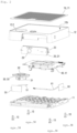
- a decoder box generally designated 1 comprises a box 10 defining an enclosure E in which are arranged an electrical module 20, a loudspeaker 30, a main electronic card or motherboard 40, a first antenna 50 and a second antenna 60.
- the box 10 is here made of a plastic material and has a height H substantially equal to 24 millimeters.
- the chassis 11 comprises a lower panel 11a, of generally rectangular shape, comprising an upper face and a lower face forming a lower face 10a of the housing 10.
- the hood 12 includes a top panel 12b and a skirt having an upper edge connected to the periphery of the top panel 12b.
- the decoder box 1 when in its nominal operating position, is installed so that the chassis 11 of the box 10 rests via four feet 13 on a substantially horizontal support (for example the piece of furniture on which the television to which the decoder box 1 is connected is also placed), and that the front face 10c of the box 10 faces the user.
- the feet 13 are received in fixing studs 11.6 provided at the four corners of the chassis 11 and are here provided with pads 14 forming decoupling points so as to limit the transmission of vibrations generated by the loudspeaker 30 to the support on which the decoder box 1 rests.
- the front panel 12c of the cover 12 comprises, on the right side, a notch 12.1 (or cutout) arranged to receive the electrical module 20.
- the notch 12.1 of generally trapezoidal shape, extends from a lower edge of said front panel 12c and comprises lateral edges and an upper edge extending in the vicinity of the front edge of the upper panel 12b, substantially parallel to the latter.
- the electrical module 20 comprises a support 21 and an electronic card 22 fixed to the support 21.
- the electronic card 22 comprises a printed circuit extending substantially parallel to the support and on which are mounted a camera, an infrared receiver and a microphone.
- the camera is arranged opposite a circular hole made in the support 21, the hole being covered by a protective glass 23 substantially flush with the front face 10c of the housing 10.
- the support 21 is here made of a material that is transparent or translucent to infrared light. This is, for example, a plastic material of the polycarbonate or MABS type (for Methyl-Acrylonitrile-Butadiene-Styrene methacrylate).
- the loudspeaker 30 is integrated into the housing 10 and comprises, in a manner known per se, a bowl 31 inside which a coil is movably mounted via a magnet, the coil being coaxially connected to a membrane 32 whose movement induces variations in acoustic pressure generating sounds.
- the bowl 31 has a central axis extending substantially vertically and comprises a square-shaped base 33 extending horizontally opposite the bottom of the cover 12 in a plane P 33 .
- the central axis of the bowl 31 is also that of the loudspeaker 30.
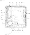
- the loudspeaker 30 is arranged in a corner of the cover 12 delimited by the front panel 12c and the left side panel 12f. It will be noted that neither of the right sides of the base 33 of the loudspeaker 30 extends here parallel to the front panel 12c or to the left side panel 12f: the side of the base 33 extending in the vicinity of the front panel 12c and the left side panel 12f forms, seen from the horizontal plane P 33 , a non-zero angle ⁇ different from 90 degrees with the front panel 12c. The angle ⁇ is here substantially equal to 25 degrees.
- a circular opening 12.2 is provided in the cover 12, coaxially with the membrane 32.
- the loudspeaker 30 is said to open into the opening 12.2. It will be noted that the opening 12.2 here has a diameter greater than that of the membrane 32 and less than the large diameter of the basket 31.
- the notch edge 46 comprises a central portion 46.1, a first lateral portion 46.2 and a second lateral portion 46.3.
- the first lateral portion 46.2 extends substantially perpendicular to the front edge 43 and connects said front edge 43 to the central portion 46.1.
- the second lateral portion 46.3 extends substantially perpendicular to the left lateral edge 45 and connects said left lateral edge 45 to the central portion 46.1.
- the first lateral portion 46.2 and the second lateral portion 46.3 have a substantially identical length, the lateral portion extending generally at 45 degrees.
- the speaker 30 is not placed above or below the motherboard 40 but next to said motherboard 40.
- the first antenna 50 and the second antenna 60 are integrated in the housing 10.
- the first antenna 50 extends parallel to the front panel 12c of the cover 12 and is pressed against it, opposite the speaker 30.
- the first antenna 50 is connected to the printed circuit 41 of the motherboard 40 via a first connection cable 51.
- the second antenna 60 extends parallel to the right side panel 12e of the cover 12 and is pressed against it, near the middle of the left side edge of the printed circuit 41 of the motherboard 40.
- the second antenna 60 is connected to the printed circuit 41 of the motherboard 40 via a second connection cable 61.
- connection ribbon cable 24 and connection cables (not shown).
- the enclosure (E) delimited by the chassis 11 and the cover 12 is not acoustically insulated so that the housing 10 does not form a closed enclosure for the loudspeaker 30. Consequently, the chassis 11 comprises ribs comprising a first series of ribs 11.1 and a second series of ribs 11.2 arranged to limit the acoustic resonance inside the housing 10 while improving the rigidity of said chassis 11.
- the first series of ribs 11.1 and the second series of ribs 11.2 extend vertically projecting from the upper face of the chassis 11 and here have a height h substantially equal to 6.4 millimeters.
- the first series of ribs 11.1 defines a honeycomb structure extending in the central part of the frame 11.
- the honeycomb structure is generally square in shape and comprises hexagonal-shaped cells 11a for breaking up standing waves.
- the cells 11a are arranged on either side of reinforcing ribs 11.3 each extending substantially along a diagonal of the honeycomb structure.
- the reinforcing ribs 11.3 each extend from a central cylindrical rib 11.4 located in the center of the chassis 11, in the direction of one of the fixing studs 11.6 receiving the feet 13.
- the second series of ribs 11.2 defines rectangular cavities 11b extending around the honeycomb structure, generally at the periphery of the chassis.
- first series of ribs 11.1 and the second series of ribs 11.2 delimit a reception zone 11.5 of a rear part of the basket 31 of the loudspeaker 30 ( figures 5 And 6 ), so that none of the ribs extend below said bottom of the salad bowl 31 so as to optimize the height H of the housing 10.
- the upper panel 12b cover 12 is covered with an insert 70 arranged to protect the loudspeaker 30 from elements external to the housing 10, and to a lesser extent from dust.
- the insert 70 comprises a plate 71 provided with a plurality of orifices equally distributed over the entire surface of the plate 71 to form a protective grid permeable to sound waves.
- the plate 71 has a lower face provided with an acoustic fabric (not shown) extending over the entire surface of the plate 71 to protect the loudspeaker 30 from dust.
- the insert 70 is here fixed on the upper panel 12b cover 12 by a double-sided adhesive.
- a recess of a height substantially equal to 1 millimeter is provided on the upper face 10b of the housing 10 to receive the insert 70.
- the insert 70 also makes it possible to mask cosmetic defects of the upper panel 12b linked to the process. plastic injection of the cover 12, and in particular the shrinkage generated during the demolding of technical functions such as the fixing studs.
- the loudspeaker 30 may be arranged elsewhere than in a corner of the cover 12 (as long as it remains oriented upwards).
- the loudspeaker 30 may for example be arranged in the middle of the upper panel 12b of the cover 12.
- the shape of the housing 10 may be different from that described and may be, for example, cylindrical.
- the first series of ribs 11.1 and the second series of ribs 11.2 may form patterns different from those described and/or have a different density.
- the angle ⁇ of inclination of the loudspeaker 30 can be zero and different from 25 degrees.
- the circular opening 12.2 into which the loudspeaker 30 opens can be replaced by a multitude of orifices.
Landscapes
- Engineering & Computer Science (AREA)
- Signal Processing (AREA)
- Physics & Mathematics (AREA)
- Acoustics & Sound (AREA)
- Multimedia (AREA)
- Health & Medical Sciences (AREA)
- Otolaryngology (AREA)
- Details Of Audible-Bandwidth Transducers (AREA)
- Casings For Electric Apparatus (AREA)
Applications Claiming Priority (1)
| Application Number | Priority Date | Filing Date | Title |
|---|---|---|---|
| FR2305999A FR3150067A1 (fr) | 2023-06-13 | 2023-06-13 | Equipement électrique intégrant un haut-parleur |
Publications (2)
| Publication Number | Publication Date |
|---|---|
| EP4489428A2 true EP4489428A2 (de) | 2025-01-08 |
| EP4489428A3 EP4489428A3 (de) | 2025-03-05 |
Family
ID=89977303
Family Applications (1)
| Application Number | Title | Priority Date | Filing Date |
|---|---|---|---|
| EP24178832.2A Pending EP4489428A3 (de) | 2023-06-13 | 2024-05-29 | Elektrische vorrichtung mit lautsprecher |
Country Status (4)
| Country | Link |
|---|---|
| US (1) | US20240422464A1 (de) |
| EP (1) | EP4489428A3 (de) |
| CN (1) | CN119135965A (de) |
| FR (1) | FR3150067A1 (de) |
Citations (1)
| Publication number | Priority date | Publication date | Assignee | Title |
|---|---|---|---|---|
| CN109951751A (zh) * | 2017-12-21 | 2019-06-28 | 听得乐股份有限公司 | 多媒体装置 |
Family Cites Families (5)
| Publication number | Priority date | Publication date | Assignee | Title |
|---|---|---|---|---|
| JP5212664B2 (ja) * | 2010-11-24 | 2013-06-19 | カシオ計算機株式会社 | スピーカの実装構造及び電子機器 |
| KR102384503B1 (ko) * | 2015-08-11 | 2022-04-12 | 삼성전자주식회사 | 슬림형 전자 장치 |
| KR20170033198A (ko) * | 2015-09-16 | 2017-03-24 | 삼성전자주식회사 | 디스플레이 장치 및 디스플레이 장치의 제어 장치 |
| US20200304892A1 (en) * | 2019-03-21 | 2020-09-24 | Wawlee, Inc. | Smart Device Systems and Methods for Providing High Fidelity Audio and Wireless Communications and Control |
| CN212909904U (zh) * | 2020-09-10 | 2021-04-06 | 深圳市佳视百科技有限责任公司 | 一种人工智能音箱系统 |
-
2023
- 2023-06-13 FR FR2305999A patent/FR3150067A1/fr active Pending
-
2024
- 2024-05-29 EP EP24178832.2A patent/EP4489428A3/de active Pending
- 2024-06-06 US US18/735,453 patent/US20240422464A1/en active Pending
- 2024-06-12 CN CN202410751288.XA patent/CN119135965A/zh active Pending
Patent Citations (1)
| Publication number | Priority date | Publication date | Assignee | Title |
|---|---|---|---|---|
| CN109951751A (zh) * | 2017-12-21 | 2019-06-28 | 听得乐股份有限公司 | 多媒体装置 |
Non-Patent Citations (1)
| Title |
|---|
| VILLEMIN G�RARD: "Carr� inscrit dans un carr�", 1 November 2023 (2023-11-01), XP093297792, Retrieved from the Internet <URL:http://villemin.gerard.free.fr/GeomLAV/Carre/CarInscr.htm> * |
Also Published As
| Publication number | Publication date |
|---|---|
| CN119135965A (zh) | 2024-12-13 |
| US20240422464A1 (en) | 2024-12-19 |
| FR3150067A1 (fr) | 2024-12-20 |
| EP4489428A3 (de) | 2025-03-05 |
Similar Documents
| Publication | Publication Date | Title |
|---|---|---|
| EP0425326B1 (de) | Befestigungs- und Dämpfungsmodul für einen Ventilator | |
| EP0342117B1 (de) | Tonanlage, besonders zur stereophonen Tonwiedergabe in einem Fernsehempfangsgerät mit integriertem Tieftonlautsprecher grosser Dimensionen | |
| BE1029479B1 (fr) | Sous–système de protection contre les infiltrions pour les microphones dans les appareils informatiques mobile | |
| FR2867937A1 (fr) | Monture de module de haut parleur, module de haut-parleur associe et dispositif electronique avec un module de haut-parleur | |
| EP4489428A2 (de) | Elektrische vorrichtung mit lautsprecher | |
| FR2499346A1 (fr) | Systeme de reproduction electro-acoustique a effet reflex | |
| FR2756126A1 (fr) | Support de panneau d'affichage a cristaux liquides pour combine telephonique de test | |
| FR2653630A1 (fr) | Structure d'enceinte acoustique. | |
| EP4478699A1 (de) | Kamera-einsatzmodul mit vertikaler montage | |
| CA2145629C (fr) | Transducteur electro-acoustique a volume diffusant | |
| EP1368987A1 (de) | Lautsprechersgehäuse und audiovisuelles gerät mit einer solchen gehäuse | |
| FR3163201A1 (fr) | Bouton poussoir pour enceinte en forme de gélule | |
| EP4433329B1 (de) | System zur drehbaren montage einer abdeckplatte für einen kraftfahrzeugkofferraum | |
| FR3121004A3 (fr) | Boîtier pour appareil électronique portable | |
| FR3157765A1 (fr) | Enceinte compacte à conception externe modulaire | |
| EP4092511B1 (de) | Infrarotbeleuchteter touchscreen-rahmen mit uvc-dioden | |
| EP3892010B1 (de) | Versteifungsteil für ein lautsprechergehäuse | |
| WO2008132320A2 (fr) | Ensemble de reproduction visuelle et sonore | |
| FR3163236A1 (fr) | Pavillon acoustique pour enceinte à surfaces courbes | |
| EP3566117B1 (de) | Vibrierende taktile fliese | |
| FR3054942A1 (fr) | Dispositif de protection d'un appareil electronique portable. | |
| WO2025061727A1 (fr) | Enceinte acoustique a joues laterales interchangeables | |
| FR2652978A1 (fr) | Enceinte acoustique. | |
| FR2658021A1 (fr) | Installation sonore pour televiseur. | |
| EP2506596B1 (de) | Kabelverbindungsvorrichtung |
Legal Events
| Date | Code | Title | Description |
|---|---|---|---|
| PUAI | Public reference made under article 153(3) epc to a published international application that has entered the european phase |
Free format text: ORIGINAL CODE: 0009012 |
|
| STAA | Information on the status of an ep patent application or granted ep patent |
Free format text: STATUS: REQUEST FOR EXAMINATION WAS MADE |
|
| 17P | Request for examination filed |
Effective date: 20240529 |
|
| AK | Designated contracting states |
Kind code of ref document: A2 Designated state(s): AL AT BE BG CH CY CZ DE DK EE ES FI FR GB GR HR HU IE IS IT LI LT LU LV MC ME MK MT NL NO PL PT RO RS SE SI SK SM TR |
|
| PUAL | Search report despatched |
Free format text: ORIGINAL CODE: 0009013 |
|
| STAA | Information on the status of an ep patent application or granted ep patent |
Free format text: STATUS: EXAMINATION IS IN PROGRESS |
|
| AK | Designated contracting states |
Kind code of ref document: A3 Designated state(s): AL AT BE BG CH CY CZ DE DK EE ES FI FR GB GR HR HU IE IS IT LI LT LU LV MC ME MK MT NL NO PL PT RO RS SE SI SK SM TR |
|
| RIC1 | Information provided on ipc code assigned before grant |
Ipc: H04N 21/426 20110101ALN20250128BHEP Ipc: H04R 1/28 20060101ALI20250128BHEP Ipc: H04R 1/02 20060101AFI20250128BHEP |
|
| 17Q | First examination report despatched |
Effective date: 20250214 |