EP4489285A1 - Umrichter und verfahren zur leistungsübertragung von einer mittelspannungsseite zu einer niederspannungsseite in einem umrichter - Google Patents
Umrichter und verfahren zur leistungsübertragung von einer mittelspannungsseite zu einer niederspannungsseite in einem umrichter Download PDFInfo
- Publication number
- EP4489285A1 EP4489285A1 EP23183646.1A EP23183646A EP4489285A1 EP 4489285 A1 EP4489285 A1 EP 4489285A1 EP 23183646 A EP23183646 A EP 23183646A EP 4489285 A1 EP4489285 A1 EP 4489285A1
- Authority
- EP
- European Patent Office
- Prior art keywords
- stage
- power
- inductor
- converter
- capacitor
- Prior art date
- Legal status (The legal status is an assumption and is not a legal conclusion. Google has not performed a legal analysis and makes no representation as to the accuracy of the status listed.)
- Pending
Links
Images


Classifications
-
- H—ELECTRICITY
- H02—GENERATION; CONVERSION OR DISTRIBUTION OF ELECTRIC POWER
- H02M—APPARATUS FOR CONVERSION BETWEEN AC AND AC, BETWEEN AC AND DC, OR BETWEEN DC AND DC, AND FOR USE WITH MAINS OR SIMILAR POWER SUPPLY SYSTEMS; CONVERSION OF DC OR AC INPUT POWER INTO SURGE OUTPUT POWER; CONTROL OR REGULATION THEREOF
- H02M3/00—Conversion of DC power input into DC power output
- H02M3/01—Resonant DC/DC converters
-
- H—ELECTRICITY
- H02—GENERATION; CONVERSION OR DISTRIBUTION OF ELECTRIC POWER
- H02M—APPARATUS FOR CONVERSION BETWEEN AC AND AC, BETWEEN AC AND DC, OR BETWEEN DC AND DC, AND FOR USE WITH MAINS OR SIMILAR POWER SUPPLY SYSTEMS; CONVERSION OF DC OR AC INPUT POWER INTO SURGE OUTPUT POWER; CONTROL OR REGULATION THEREOF
- H02M1/00—Details of apparatus for conversion
- H02M1/0048—Circuits or arrangements for reducing losses
- H02M1/0054—Transistor switching losses
-
- H—ELECTRICITY
- H02—GENERATION; CONVERSION OR DISTRIBUTION OF ELECTRIC POWER
- H02M—APPARATUS FOR CONVERSION BETWEEN AC AND AC, BETWEEN AC AND DC, OR BETWEEN DC AND DC, AND FOR USE WITH MAINS OR SIMILAR POWER SUPPLY SYSTEMS; CONVERSION OF DC OR AC INPUT POWER INTO SURGE OUTPUT POWER; CONTROL OR REGULATION THEREOF
- H02M3/00—Conversion of DC power input into DC power output
- H02M3/22—Conversion of DC power input into DC power output with intermediate conversion into AC
- H02M3/24—Conversion of DC power input into DC power output with intermediate conversion into AC by static converters
- H02M3/28—Conversion of DC power input into DC power output with intermediate conversion into AC by static converters using discharge tubes with control electrode or semiconductor devices with control electrode to produce the intermediate AC
- H02M3/325—Conversion of DC power input into DC power output with intermediate conversion into AC by static converters using discharge tubes with control electrode or semiconductor devices with control electrode to produce the intermediate AC using devices of a triode or a transistor type requiring continuous application of a control signal
- H02M3/335—Conversion of DC power input into DC power output with intermediate conversion into AC by static converters using discharge tubes with control electrode or semiconductor devices with control electrode to produce the intermediate AC using devices of a triode or a transistor type requiring continuous application of a control signal using semiconductor devices only
- H02M3/33569—Conversion of DC power input into DC power output with intermediate conversion into AC by static converters using discharge tubes with control electrode or semiconductor devices with control electrode to produce the intermediate AC using devices of a triode or a transistor type requiring continuous application of a control signal using semiconductor devices only having several active switching elements
- H02M3/33571—Half-bridge at primary side of an isolation transformer
Definitions
- aspects of the invention relate to a converter, particularly a DC/DC converter having a medium voltage side and a low voltage side galvanically insulated from the medium voltage side. Aspects of the invention particularly relate to a solid-state converter suitable for providing a grid-insulated DC power in the megawatt range. Aspects of the invention particularly relate to a transformer-less converter.
- Converters are often utilized for converting electric power for applications such as renewables (photovoltaic, wind), energy storage (battery, hydrogen, fuel cells), electric machines such as large drives, electric vehicle charging, and datacenters.
- renewables photovoltaic, wind
- energy storage battery, hydrogen, fuel cells
- electric machines such as large drives, electric vehicle charging, and datacenters.
- a converter is often provided between the power consumer or producer, and a medium voltage power grid.
- a general requirement for such converters is to provide an essentially constant output voltage, essentially constant output power, and to draw and/or provide approximately sinusoidal currents to/from the medium voltage grid, which are in phase with the grid phase voltages to achieve power-factor correction functionality.
- Known converters may utilize a design in which a high-frequency AC power is generated and transferred between a medium voltage stage and a low-voltage stage by a transformer, particularly a medium frequency transformer, which provides galvanic insulation between the medium voltage grid and the low-voltage side.
- the use of a medium frequency transformer may be undesirable due to factors such as initial cost, operating cost, space requirement, system complexity, and/or conversion efficiency.
- the present invention solves the problem at least in part.
- a converter includes at least one DC/AC stage configured for generating a medium frequency AC power and having first and second AC outputs for the medium frequency AC power, at least one AC/DC stage configured for generating a DC power from the medium frequency AC power and having first and second AC inputs for the medium frequency AC power, and a resonant circuit provided between the DC/AC stage and the AC/DC stage and configured for transferring the medium frequency AC power.
- the resonant circuit includes at least two capacitors including a first capacitor and a second capacitor. The first capacitor is connected between the first AC output and the first AC input, and the second capacitor is connected between the second AC output and the second AC input.
- the resonant circuit further includes at least two inductors including a first inductor and a second inductor connected in series and defining a connection point between the two inductors.
- the first inductor is connected in series between the first capacitor and the first AC input
- the second inductor is connected in series between the first AC input and the second AC input.
- the first inductor is connected in series between the first capacitor and the first AC output
- the second inductor is connected in series between the first AC output and the second AC output.
- the at least two capacitors provide galvanic insulation between the DC/AC stage and the AC/DC stage.
- a method of transferring power from a medium voltage side to a low voltage side in a converter includes generating a medium frequency AC power at the medium voltage side, providing the medium frequency AC power to an AC/DC stage at the low voltage side through a resonant circuit, and providing galvanic insulation between AC outputs of the medium voltage side and AC inputs of the low voltage side by at least two capacitors.
- the resonant circuit includes the at least two capacitors including a first capacitor and a second capacitor. The first capacitor is connected between the first AC output and the first AC input, and the second capacitor is connected between the second AC output and the second AC input.
- the resonant circuit includes at least two inductors including a first inductor and a second inductor connected in series and defining a connection point between the two inductors.
- the first inductor is connected in series between the first capacitor and the first AC input
- the second inductor is connected in series between the first AC input and the second AC input.
- the first inductor is connected in series between the first capacitor and the first AC output
- the second inductor is connected in series between the first AC output and the second AC output.
- a converter may be configured for converting a first DC voltage into a second DC voltage.
- the first DC voltage and the second DC voltage may have the same potential.
- the first DC voltage may have a different potential than the second DC voltage.
- the converter may operate as a transformer and/or a step-down converter.
- the converter may operate as a step-up converter.
- the converter may be configured for converting a medium voltage DC power into a low voltage DC power.
- the converter may be a DC/DC converter.
- the converter may include a rectifier stage to generate the medium voltage DC power from a medium voltage AC power, such as a medium voltage AC power received from a medium voltage grid.
- the converter may be an AC/DC converter.
- the converter may be configured for stepping down the medium voltage DC power.
- the converter may be a solid-state transformer.
- the converter may be devoid of a transformer, such as a medium frequency transformer, a transformer having windings provided on a magnetic core, and/or an induction-based transformer.
- a transformer such as a medium frequency transformer, a transformer having windings provided on a magnetic core, and/or an induction-based transformer.
- the low voltage DC power may be particularly useful for low voltage DC applications, such as, but not limited to, powering devices, electric vehicle charging, electrolytic processes such as hydrogen generation, and/or any of the uses described in the background section of this disclosure.
- the converter may be configured for providing a low voltage DC power having at least 500 Kilowatt (kW), at least 1 MW, at least 2 MW, at least 3 MW, at least 5 MW, or even at least 10 MW.
- a low voltage may be a voltage above 200 Volt (V), such as a voltage between 200 V - 1 kV, or even 200 V - 1.5 kV, or even 200 V - 2 kV.
- V Volt
- a medium voltage is described.
- a medium voltage may be voltage higher than the low voltage, such as a voltage of above 1 kV, or even of above 1.5 kV, or even above 2 kV, such as a voltage between 1 kV - 52 kV, 1.5 kV - 52 kV, or 2 kV - 52 kV, particularly between 1 kV - 30 kV, 1.5 kV - 30 kV, or 2 kV - 30 kV, such as about 15 kV.
- a medium voltage may be a voltage received, and optionally rectified, from a medium voltage grid, such as a 10 kV grid, a 15 kV grid, a 20 kV grid, a 25 kV grid, a 30 kV grid, or even a 50 kV grid.
- the medium voltage grid may be e.g. a 50 Hz grid or a 60 Hz grid.
- the converter includes a solid state transformer.
- the converter may be a solid state transformer.
- the converter may include a plurality of solid state transformers. The converter being configured for or operated as a solid state transformer does not necessarily infer that the converter includes an induction-based transformer.
- the converter includes a medium voltage side.
- the medium voltage side includes a DC/AC stage.
- the medium voltage side includes an inverter circuit.
- the inverter circuit may include an inverter, such as an inverter configured for switching a medium voltage DC power to provide a medium frequency AC power.
- the inverter circuit may include a plurality of semiconductor components, such as a plurality of semiconductor switches.
- the medium voltage side may be defined as a portion of the converter that is not galvanically insulated from, and/or (directly) electrically connected to a medium voltage grid.
- the medium voltage side may be floating, e.g. not be connected to a ground potential.
- the converter includes a low voltage side.
- the low voltage side includes an AC/DC stage.
- the low voltage side includes a rectifier, particularly for rectifying a medium frequency AC power generated by the medium voltage DC/AC stage to obtain a low voltage DC power.
- the low voltage side may be defined as a portion of the converter that is galvanically insulated from the medium voltage side.
- the low voltage side may be grounded, e.g. include grounded components and/or have a defined ground and/or earth potential.
- the low voltage side may be connectable to grounded components, e.g. to transfer a low voltage DC power to and/or from the grounded components.
- the converter may be configured for receiving a power, e.g. from a medium voltage grid, and converting the power into a low voltage DC power to be used by an electric consumer.
- the converter may be configured for receiving a low voltage DC power, and converting the low voltage DC power into a medium voltage DC power, or even a medium voltage AC power, e.g. to be fed into a medium voltage grid.
- the converter may be configured for bi-directional operation. In some applications, e.g.
- the side of the converter connected to the power grid may be considered the low voltage side
- the side of the converter connected to the local power source may be considered the medium voltage side
- the converter may include a plurality of semiconductor devices.
- the semiconductor devices may be described as transistors and/or diodes, particularly semiconductor diodes such as silicon diodes. Different types of semiconductor devices, such as switchable semiconductor devices may be provided.
- the DC/AC stage may include actively switchable semiconductor devices, such as transistors and/or thyristors, such as a metal-oxide-semiconductor field-effect transistor (MOSFET), an insulated-gate bipolar transistor (IGBT), high-electron-mobility transistor (HEMT), or an integrated gate-commutated thyristor (IGCT).
- transistors and/or thyristors such as a metal-oxide-semiconductor field-effect transistor (MOSFET), an insulated-gate bipolar transistor (IGBT), high-electron-mobility transistor (HEMT), or an integrated gate-commutated thyristor (IGCT).
- MOSFET metal-oxide-semiconductor field-effect transistor
- IGBT insulated-gate bipolar transistor
- HEMT high-electron-mobility transistor
- IGCT integrated gate-commutated thyristor
- the converter may be described herein as being suitable for converting a medium voltage DC power into a low voltage DC power, the potential of the low voltage DC power being lower than the potential of the medium voltage DC power, the converter may likewise generate a low voltage DC power having essentially the same potential as the medium voltage DC power, or even a low voltage DC power having a higher potential than the medium voltage DC power.
- the converter may include a plurality of (sub-)converters.
- the converter may include (sub-)converters arranged in a Single-Input-Single-Output (SISO), Single-Input-Multiple-Output (SIMO), Multiple-Input-Multiple-Output (MIMO) and/or Input-Series-Output-Parallel (ISOP) topology.
- SISO Single-Input-Single-Output
- SIMO Single-Input-Multiple-Output
- MIMO Multiple-Input-Multiple-Output
- ISOP Input-Series-Output-Parallel
- a plurality of converters and/or converter modules may be provided in a SISO, SIMO, MIMO and/or ISOP topology, e.g. to provide a single low voltage DC power from multiple medium voltage DC powers, or to provide multiple low voltage DC powers from a single medium voltage DC power.
- the multiple medium voltage DC powers may be generated by rectifying one or more phases of a multi-phase, such as a three-phase, medium voltage AC power.
- a multi-phase such as a three-phase, medium voltage AC power.
- Some configurations, such as the ISOP configuration may allow generating a low voltage DC (output) power having a lower potential than the medium voltage DC (input) power, particularly without including or utilizing induction-based voltage level transformation and/or transformers.
- the converter includes a resonant circuit provided between outputs of the DC/AC stage and inputs of the AC/DC stage.
- the resonant circuit may be configured for transferring a medium frequency AC power generated by the DC/AC stage to the AC/DC stage, and/or electrically coupling the DC/AC stage to the AC/DC stage.
- the resonant circuit may be configured for capacitively coupling outputs of the DC/AC stage to the AC/DC stage.
- the resonant circuit includes at least two capacitors.
- the capacitors may be provided as single capacitors, or capacitor assemblies including serially and/or parallel connected capacitors, such as capacitor banks, functionally resembling a single capacitor.
- a capacitor bank may include a plurality of series connected capacitors, a plurality of parallel connected capacitors, and/or a plurality of series-parallel-connected capacitors.
- a first capacitor is connected between a first AC output of the DC/AC stage and a first AC input of the AC/DC stage, and a second capacitor is connected between a second AC output of the DC/AC stage and a second input of the AC/DC stage.
- a first node of the first capacitor may be connected to an AC output, and a second node of the first capacitor may be indirectly connected to an AC input, particularly by being connected in series to a first inductor, the first inductor being connected to the AC input.
- a first node of the second capacitor may be connected to an AC output, and a second node of the second capacitor may be directly connected to an AC input.
- the capacitor may be connected in series between the AC output and the AC input.
- the AC output is galvanically insulated from the AC input by the capacitor. Accordingly, the DC/AC stage and the AC/DC stage are galvanically insulated by the at least two capacitors. Accordingly, the medium voltage side of the converter may be galvanically insulated from the low voltage side of the converter by the at least two capacitors.
- the resonant circuit includes two inductors including a first inductor and a second inductor connected in series, particularly connected in series to one another.
- the two inductors define a connection point between the inductors.
- the connection point may be connected to an AC input.
- the first inductor may be connected in series between the first capacitor and the first AC input
- the second inductor may be connected in series between the first AC input and the second AC input.
- both inductors may be provided on the low voltage side of the converter, or may be provided on the medium voltage side of the converter.
- the first inductor and the second inductor may be connected in series to the low voltage side nodes of the first capacitor and the second capacitor.
- a first node of the second inductor, particularly a node defining the connection point, may be connected to a first AC input
- a second node particularly a node other than the connection point, may be connected to the second capacitor and a second AC input.
- the first inductor is connected to the first capacitor at an AC/DC side of the capacitor
- the at least two inductors are connected, at the connection point, to an input of the AC/DC stage
- the second inductor is connected to the second capacitor at an AC/DC side of the capacitor.
- the first inductor is connected to the first capacitor at a DC/AC side of the capacitor, the at least two inductors are connected, at the connection point, to an output of the DC/AC stage, and the second inductor is connected to the second capacitor at a DC/AC side of the capacitor.
- the first inductor may be connected in series between the first capacitor and the first AC output
- the second inductor may be connected in series between the first AC output and the second AC output.
- both inductors may be provided on the medium voltage side of the converter.
- the first inductor and the second inductor may be connected in series to the medium voltage side nodes of the first capacitor and the second capacitor.
- a first node of the second inductor, particularly a node defining the connection point may be connected to a first AC output
- a second node, particularly a node other than the connection point may be connected to the second capacitor and a second AC output.
- the at least two inductors may each be connected, at a point other than the connection point, to the at least two capacitors and providing an inductance between the at least two capacitors.
- the capacitors and the inductors form a resonant circuit, i.e. a circuit having a resonant frequency, such as an LC-circuit.
- the converter particularly the DC/AC stage, may be configured to operate at the resonant frequency.
- the DC/AC stage may generate a signal having a frequency f, such as an essentially rectangular voltage signal, however, other signal types, such as sinusoidal or quasi-sinusoidal signals may be contemplated.
- the DC/AC stage may be configured to provide the medium frequency AC power at the resonant frequency of the resonant circuit.
- the design and/or control of the DC/AC stage may be simple.
- the resonant frequency of the resonant circuit may be essentially defined by the first inductor and the first and second capacitor.
- the capacitance C of the first capacitor and the second capacitor may be identical, i.e. has the same value.
- the first inductance L 1 of the first inductor may be smaller than the second inductance L 2 of the second inductor.
- the ratio L 1: L 2 may be 1:10 or more, 1:20 or more, 1:50 or more, or even 1:100 or more.
- the second inductor is configured for shaping a current at zero crossings of the current.
- the second inductor may operate as a filter within the resonant circuit.
- the second inductor may be configured to shape the current such that switching losses in the DC/AC converter are reduced.
- the inductance L 2 may be chosen such that the current of the resonant circuit is low or even near-zero when switching e.g. from a positive half-wave to a negative half-wave.
- the inductance L 2 may compensate a potential phase-shift of the resonant circuit with respect to the medium frequency AC voltage.
- the current shaping of the inductance L 2 may improve the power efficiency of the converter, and may beneficially improve power density of the converter due to the converter being operable at higher load and/or frequency.
- Fig. 1 shows a converter 100 according to an embodiment.
- a DC/AC stage 110 is configured for generating a medium frequency AC power from a DC power provided by a DC power source 112.
- the DC/AC stage has a first output 114 and a second output 116.
- a first node of a first capacitor C 1 is connected to the first output 114, and a first node of a second capacitor C 2 is connected to the second output 116.
- the capacitors C 1 and C 2 provide galvanic insulation 140.
- a medium voltage side including the DC power source 112 and the DC/AC stage 110 is galvanically insulated from a low voltage side, the low voltage side including e.g. the AC/DC stage 120 and a load 122.
- the capacitors C 1 and C 2 form a part of a resonant circuit 130.
- the resonant circuit 130 further includes the inductors L 1 and L 2 .
- a first node of the first inductor L 1 is connected to a second node of the first capacitor C 1 .
- a second node of the second inductor L 2 is connected to a second node of the second capacitor C 2 .
- a second node of the first inductor L 1 is connected to a first node of the second inductor L 2 , defining a connection point.
- the connection point is connected to a first input 124 of the AC/DC stage 120.
- the second node of the second inductor L 2 , and the second node of the second capacitor C 2 are connected to a second input 126 of the AC/DC stage.
- the DC/AC stage 110 may generate a medium frequency AC power, and provide the medium frequency AC power at the outputs 114, 116.
- the frequency of the medium frequency AC power may be a resonant frequency of the resonant circuit 130, particularly as defined by the capacitance of the capacitors C 1 , C 2 , and the inductance of the first inductor L 1.
- the medium frequency AC power may have a medium frequency.
- a medium frequency may be understood as a frequency at or above 400 Hertz (Hz), at or above 600 Hz, at or above 800 Hz, at or above 1 kHz, at or above 2 kHz, at or above 5 kHz, at or above 10 kHz, at or above 20 kHz, at or above 50 kHz, or even at or above 100 kHz.
- the medium frequency AC power may have a frequency of about 20 kHz.
- the frequency of the medium frequency AC power may be tuned according to the calculated and/or measured resonance frequency of the resonant circuit 130.
- the values of the components of the resonant circuit particularly the values of the capacitors C 1 , C 2 , and the value of the inductor L 1 , may be chosen, e.g. during design and/or construction of the converter, to define the resonant frequency of the resonant circuit 130.
- one or more components of the resonant circuit 130 may be prefabricated components.
- the capacitors C 1 , C 2 may be prefabricated components, having a pre-defined capacitance, power- and/or frequency rating.
- the capacitors C 1 , C 2 may be fabricated from pre-fabricated components, such as by fabricating a capacitor bank including prefabricated capacitor elements.
- the resonant circuit 130 may be adapted according to parameters and/or limits of the capacitors C 1 , C 2 .
- the target frequency of the converter may be chosen based on a given capacitance of the capacitors and a target power output. Accordingly, a value for the inductor L 1 may be calculated so that the resonant circuit 130 has a resonant frequency at the target frequency.
- the resonant circuit 130 includes a second inductor L 2 , connected between the inputs 124, 126 of the AC/DC stage 120.
- the inductance of the second inductor L 2 is larger than the inductance of the first inductor. Accordingly, the effect of the second inductor on the resonant frequency of the resonant circuit 130 may be essentially neglected.
- the inductor L 2 may be configured for current shaping, particularly such that switching losses in the DC/AC stage are minimized.
- the inductance of the inductor L 2 may be chosen such that, when the resonant circuit 130 is operated at the resonant frequency, switching between e.g. a positive half-wave and a negative half-wave occurs at or near a zero current point, and/or even a zero voltage point.
- the medium frequency AC power may be provided at a frequency of about 20 kHz.
- the capacitors C 1 , C 2 may each have a capacitance of about 5 ⁇ F - 15 ⁇ F, such as about 14 ⁇ F.
- the first inductor L 1 may have an inductance of about 5 ⁇ H - 15 ⁇ H, such as about 9 ⁇ H.
- the second inductor L 2 may have an inductance of about 1 mH. Further potential configurations, e.g. for alternative frequencies f, may be derived according to equation (1) described herein.
- the power transferrable by the resonant circuit may be substantially increased, with only a marginal increase in capacitor cost of the capacitors C 1 and C 2 .
- the converter 100 may be operated at an output voltage of the DC power of 750 V or more, 1 kV or more, 2 kV or more, or even 4 kV or more.
- the DC/AC stage 110 is a DC/AC stage known in the art.
- the DC/AC stage 110 may be an inverter.
- the DC/AC stage 110 may be a full-bridge and/or H-bridge inverter.
- the DC/AC stage 110 may be a half-bridge inverter, e.g. as shown in Fig. 4 .
- the AC/DC stage 120 is an AC/DC stage known in the art.
- the AC/DC stage 120 may be a rectifier.
- the AC/DC stage may be a full-bridge rectifier.
- the AC/DC stage may be a half-bridge rectifier.
- the AC/DC stage may be bridge voltage doubler, such as a Delon circuit, e.g. as shown in Fig. 4 .
- the converter may be a bi-directional converter.
- the AC/DC stage may receive power on the side of the AC/DC stage 120, and operate the AC/DC stage 120 as a DC/AC stage, e.g. as described with respect to the DC/AC stage 110.
- the AC/DC stage may operate as an AC/DC stage, e.g. as described with respect to the AC/DC stage 120.
- the converter 100 is devoid of a transformer. Accordingly, the resonant circuit 130 is generally not configured for stepping up and/or stepping down the medium frequency AC voltage between the outputs 114, 116 and the inputs 124, 126.
- the converter 200 shown in Fig. 2 may be the converter 100 shown in Fig. 1 being operated in a reverse direction, e.g. as a second operation mode of a bi-directional converter.
- the converter 200 shown in Fig. 2 differs from the converter 100 shown in Fig. 1 in that the inductors L 1 and L 2 are provided on the medium voltage side of the converter. Accordingly, a first node of the first inductor L 1 is connected to a first node of the first capacitor C 1 . A second node of the second inductor L 2 is connected to a first node of the second capacitor C 2 . A second node of the first inductor L 1 is connected to a first node of the second inductor L 2 , defining a connection point. The connection point is connected to a first output 114 of the DC/AC stage 110. The second node of the second inductor L 2 , and the first node of the second capacitor C 2 are connected to a second output 116 of the DC/AC stage 110.
- a second node of a first capacitor C 1 is connected to the first input 124, and a second node of a second capacitor C 2 is connected to the second input 126.
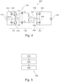
- the converter 300 includes a plurality of converters 100 1 , 100 2 , 100 3 , which may be converters 100 e.g. as described with reference to Fig. 1 and Fig. 2 .
- the DC/AC stages 110 1 , 110 2 , 110 3 of the plurality of converters 100 1 , 100 2 , 100 3 are connected in series to the DC power source 112. Accordingly, the DC/AC stages 110 1 , 110 2 , 110 3 essentially operate as a voltage divider.
- the converter 300 may include utilize a plurality of converters 200.
- a resonant circuit and an DC/AC stage 110 1 , 110 2 , 110 3 is provided for each of the plurality of AC/DC stages 120 1 , 120 2 , 120 3 .
- the converter 300 is configured for providing a DC output power having a potential that is lower than the potential of the input power.
- the converter 300 may be a SIPO converter.
- the converter 300 may be configured for providing a low voltage DC output power having a voltage of at least 500 V, at least 750 V, at least 1 kV, or even at least 2 kV.
- the converter 300 may be configured for providing the low voltage DC output power having a power of at least 500 kW, at least 1 MW, at least 2 MW, or even at least 3 MW. It should be noted that the output power may be a sum of the powers provided by the plurality of converters 100 in the converter 300.
- the converter 300 may be configured for generating a DC output power at 750 V at a rated output power of 3 MW.
- the medium frequency AC power at the outputs of the DC/AC stage may have a voltage of about 21 kV, e.g. by being generated from rectifying a medium voltage AC power received from a 15 kV medium voltage grid.
- the converter 300 may include 31 converters 100 connected in a SIPO configuration as shown in Fig. 3 . Each capacitor C 1 , C 2 may have a capacitance of 6.5 ⁇ F.
- the resonant circuits 130 may be rated for operating at a medium frequency AC power having a frequency of 20 kHz.
- Each converter 100 may be rated for providing about 97 kW.
- Each converter 100 may be configured for operating at a current of about 258 A.
- Each capacitor C 1 , C 2 may be provided by connecting 13 capacitor elements in parallel to form a capacitor bank, the number of required capacitor elements being essentially defined by the current rating of the converter.
- Each inductor L 1 may have an inductance of about 9.75 ⁇ H, and be rated for a maximum current of about 365 A.
- the converter 300 may be configured for generating a DC output power at 1000 V at a rated output power of 3 MW.
- the medium frequency AC power at the outputs of the DC/AC stage may have a voltage of about 21 kV, e.g. by being generated from rectifying a medium voltage AC power received from a 15 kV medium voltage grid.
- the converter 300 may include 23 converters 100 connected in a SIPO configuration as shown in Fig. 3 .
- Each capacitor C 1 , C 2 may have a capacitance of 6.5 ⁇ F.
- the resonant circuits 130 may be rated for operating at a medium frequency AC power having a frequency of 20 kHz.
- Each converter 100 may be rated for providing about 130 kW.
- Each converter 100 may be configured for operating at a current of about 261 A.
- Each capacitor C 1 , C 2 may be provided by connecting 13 capacitor elements in parallel to form a capacitor bank, the number of required capacitor elements being essentially defined by the current rating of the converter.
- Each inductor L 1 may have an inductance of about 9.75 ⁇ H, and be rated for a maximum current of about 369 A.
- the converter 300 may be configured for generating a DC output power at 2000 V at a rated output power of 3 MW.
- the medium frequency AC power at the outputs of the DC/AC stage may have a voltage of about 21 kV, e.g. by being generated from rectifying a medium voltage AC power received from a 15 kV medium voltage grid.
- the converter 300 may include 11 converters 100 connected in a SIPO configuration as shown in Fig. 3 .
- Each capacitor C 1 , C 2 may have a capacitance of 7 ⁇ F.
- the resonant circuits 130 may be rated for operating at a medium frequency AC power having a frequency of 20 kHz.
- Each converter 100 may be rated for providing about 273 kW.
- Each converter 100 may be configured for operating at a current of about 273 A.
- Each capacitor C 1 , C 2 may be provided by connecting 14 capacitor elements in parallel to form a capacitor bank, the number of required capacitor elements being essentially defined by the current rating of the converter.
- Each inductor L 1 may have an inductance of about 9 ⁇ H, and be rated for a maximum current of about 385 A.
- the converter 300 may be configured for generating a DC output power at 4000 V at a rated output power of 3 MW.
- the medium frequency AC power at the outputs of the DC/AC stage may have a voltage of about 21 kV, e.g. by being generated from rectifying a medium voltage AC power received from a 15 kV medium voltage grid.
- the converter 300 may include 5 converters 100 connected in a SIPO configuration as shown in Fig. 3 .
- Each capacitor C 1 , C 2 may have a capacitance of 7.5 ⁇ F.
- the resonant circuits 130 may be rated for operating at a medium frequency AC power having a frequency of 20 kHz.
- Each converter 100 may be rated for providing about 600 kW.
- Each converter 100 may be configured for operating at a current of about 300 A.
- Each capacitor C 1 , C 2 may be provided by connecting 15 capacitor elements in parallel to form a capacitor bank, the number of required capacitor elements being essentially defined by the current rating of the converter.
- Each inductor L 1 may have an inductance of about 8.5 ⁇ H, and be rated for a maximum current of about 424 A.
- each capacitor C 1 , C 2 provides galvanic insulation 140 between the medium voltage side and the low voltage side of the converter 100, 300.
- the capacitors C 1 , C 2 may be configured for providing lightning impulse insulation.
- each capacitor C 1 , C 2 may be rated for a surge voltage of above 50 kV, above 75 kV, such as above 80 kV, or even above 100 kV.
- the converter 300 since the voltage rating of the capacitors C 1 , C 2 may be defined by the required lightning impulse insulation, and as is evident from the examples given above, the converter 300 may be particularly efficient when operating at a higher rated DC power output voltage.
- the converter 400 may be an implementation of the converter 100 described herein.
- the converter 400 may be adapted to reflect the topology of the converter 200 shown in Fig. 2 , particularly by providing the inductors at the medium voltage side of the converter 400, without deriving form the scope of this disclosure.
- the DC/AC stage 110 is implemented as a half-bridge inverter and/or a half H-bridge inverter, including two capacitors 412, 414 connected to the DC power source 112 and defining a second neutral point at the second output 116. Accordingly, the second capacitor C 2 is connected to the second neutral point.
- the DC/AC stage 110 further includes two electronic switches 416, 418, such as transistors or thyristors, configured for generating a medium frequency AC power at the first output 114 and/or between the first output 114 and the second output 116.
- the two electronic switches 416, 418 may be implemented as a plurality of series connected electronic switches.
- the converter 400 may include a controller and/or driving circuit (not shown) for controlling the electronic switches 416, 416, e.g. by providing timed control signals to the inputs and/or gates of the electronic switches 416, 418, e.g. according to methods known in the art.
- the controller may be configured for causing the DC/AC stage 110 to generate a medium frequency AC power having a medium frequency, such as a 20 kHz.
- the AC/DC stage 120 is implemented as a half-bridge rectifier, particularly as a full-wave voltage doubler and/or Delon circuit.
- the rectifier includes two capacitors 422, 424 connected to outputs of the AC/DC stage and/or the load 122 and defining a first neutral point.
- the first neutral point is connected to the second input 126 of the AC/DC stage.
- the second capacitor C 2 and the second inductor L 2 is connected to the second neutral point.
- the AC/DC stage 120 further includes two diodes 426, 428, such as silicon diodes, configured for rectifying the medium frequency AC power received at the inputs 124, 126 of the AC/DC stage.
- diodes 426, 428 such as silicon diodes
- the medium frequency AC power may have a voltage of half the voltage of the power provided by the DC power source.
- the AC/DC stage may act as a voltage doubler. Accordingly, the voltage of the low voltage DC output power may be essentially the same as the voltage of the power provided by the DC power source.
- the components of the resonant circuit 130 may be configured for a lower rated voltage, such as half the voltage of the power provided by the DC power source.
- the capacity of one or more of the capacitors 412, 414, 422, 424 may be between 10 ⁇ F to 1000 ⁇ F, such as between 50 ⁇ F and 500 ⁇ F, such as about 100 ⁇ F.
- the first neutral point is a neutral point of the AC/DC stage
- the second neutral point is a neutral point of the DC/AC stage.
- the first neutral point may be a neutral point of the DC/AC converter
- the second neutral point may be a neutral point of the AC/DC stage.
- the converter 400 may be configured as a bi-directional converter.
- a bi-directional converter may allow transferring a power in either direction.
- the bi-directional converter may be configured for receiving a power from the DC power source 112 and feeding a power into the load 122, and likewise be operable to receive a power from the load 122 and feeding a power into the DC power source 112.
- the bi-directional converter may include an AC/DC stage 120 similar to the DC/AC stage 110.
- the AC/DC stage may be an inverter circuit. Accordingly, in the bi-directional converter, the AC/DC stage 120 may be operable as either a rectifier or an inverter. Likewise, the DC/AC stage 110 may be operable either as a rectifier or an inverter. Accordingly, the AC/DC stage 120 may include a controller and/or driving circuit (not shown) for controlling the electronic switches of the AC/DC stage. The controller may be the controller as described for the DC/AC stage 110, or a separate controller.
- the converter 400 has been described as having half-bridge configuration for the DC/AC stage 110 and the AC/DC stage 120, further and/or alternative configurations or combinations thereof may be equally suitable.
- the converter 400 may include a half-bridge configuration at the DC/AC stage 110, and a full-bridge rectifier at the AC/DC stage 120.
- the converter 400 may include a full-bridge configuration at the DC/AC stage 110, and a half-bridge at the AC/DC stage 120.
- the converter 400 may include a full-bridge configuration at both the DC/AC stage 110 and the AC/DC stage.
- the method 500 may include the use of a converter 100, 200, 300, 400 according to embodiments described herein.
- the method 500 may include operating a converter 100, 200, 300, 400 according to embodiments described herein according to the method 500.
- the method 500 includes generating 510 a medium frequency AC power at the medium voltage side.
- the medium frequency AC power may be a medium frequency AC power as described herein with reference to aspects and/or embodiments.
- the medium frequency AC power may be generated by a DC/AC stage 110 as described herein with reference to embodiments.
- the method further includes providing 520 the medium frequency AC power to an AC/DC stage at the low voltage side through a resonant circuit.
- the AC/DC stage may be an AC/DC stage 120 as described herein with reference to embodiments.
- the resonant circuit may be a resonant circuit 130 as described herein with reference to embodiments.
- the method includes providing 530 galvanic insulation between AC outputs of the medium voltage side and AC inputs of the low voltage side by at least two capacitors, such as the capacitors C 1 , C 2 of the resonant circuit 130.
- the operations 510, 520, and 530 may be executed in any order, and may be executed in parallel and/or in part.
- galvanic insulation may be provided 530 independently of the operations 510, 520. This may beneficially provide lightning impulse insulation between the medium voltage side and the low voltage side of the converter, even if the converter is in an unpowered state.
- generating 510 the medium frequency AC power, and/or providing 520 the medium frequency AC power may include generating the medium frequency AC power at a resonant frequency of the resonant circuit.
- the method 500 may include tuning the value of the first inductor to define the resonant frequency of the resonant circuit.
- Tuning in the context of this disclosure, may be understood as choosing a value of the first inductor during design, configuration and/or construction, to define a resonant frequency of the resonant circuit according to a predefined target resonant frequency.
- the target resonant frequency, and/or the capacity of the capacitors of the resonant circuit may be set e.g. due to design constraints, and the inductance of the first inductor may be variable.
- the method 500 may include tuning the value of the second inductor to minimize switching losses by minimizing a current, particularly a current flowing through an electronic switch of the DC/AC stage, at the zero crossings of the current.
- a zero crossing of the current may be defined as the DC/AC switching the medium frequency AC power between positive and negative half-waves.
- Tuning in the context of this disclosure, may be understood as choosing a value of the second inductor during design, configuration and/or construction.
- the value of the second inductor may be chosen so that a phase shift of the resonant circuit with respect to the medium frequency AC power at the outputs of the DC/AC stage are minimized.
- the value of the second inductor may be chosen so that the second inductor acts as a filter.
- the value of the second inductor may be chosen so that the second inductor acts as a decoupling inductance.
- the value of the second inductor may be chosen such that the second inductor acts as an energy storage inductor.
- tuning the value of the first inductor and/or the second inductor may include design operations known in the art, such as a simulation of the resonant circuit and/or waveform analysis, phase shift correction calculations, or the like.
- the first capacitor C 1 and the second capacitor C 2 of a converter 100, 200, 300, 400 may be provided as components in a converter installation, the converter installation physically separating the medium voltage side of the converter from the low voltage side of the converter, e.g. by minimum safety distance.
- the capacitors C 1 , C 2 may each include one or more bushings.
- the bushings may be configured for receiving a connector, such as a cable shoe, from the medium voltage side of the converter, such as the outputs 114, 116 of the DC/AC stage 110.
- the bushings may be configured for providing medium voltage insulation.
- the bushings may be configured for providing a minimum safe distance between the connector and the low voltage side of the converter.
- the bushing may be integrated into the capacitor.
- the bushing may be integrated into a housing of the capacitor bank.
- the inductors L 1 , L 2 are uncoupled inductors.
- the inductors may not be required to be provided e.g. as windings on the same magnetic core.
- the inductors may be provided as separate coils, e.g. at different places within the converter 100, 200, 300, 400, such as at different positions on a printed circuit board.
- the inductors L 1 , L 2 may coupled inductors.
- the inductors may be provided as windings on the same magnetic core.
- the inductance of each inductor L 1 , L 2 may be defined by the number of turns of each of the windings.
- the inductors may be provided as an autotransformer. A tap on the autotransformer may define the connection point of the inductors L 1 , L 2 .
Landscapes
- Engineering & Computer Science (AREA)
- Power Engineering (AREA)
- Inverter Devices (AREA)
Priority Applications (1)
| Application Number | Priority Date | Filing Date | Title |
|---|---|---|---|
| EP23183646.1A EP4489285A1 (de) | 2023-07-05 | 2023-07-05 | Umrichter und verfahren zur leistungsübertragung von einer mittelspannungsseite zu einer niederspannungsseite in einem umrichter |
Applications Claiming Priority (1)
| Application Number | Priority Date | Filing Date | Title |
|---|---|---|---|
| EP23183646.1A EP4489285A1 (de) | 2023-07-05 | 2023-07-05 | Umrichter und verfahren zur leistungsübertragung von einer mittelspannungsseite zu einer niederspannungsseite in einem umrichter |
Publications (1)
| Publication Number | Publication Date |
|---|---|
| EP4489285A1 true EP4489285A1 (de) | 2025-01-08 |
Family
ID=87158427
Family Applications (1)
| Application Number | Title | Priority Date | Filing Date |
|---|---|---|---|
| EP23183646.1A Pending EP4489285A1 (de) | 2023-07-05 | 2023-07-05 | Umrichter und verfahren zur leistungsübertragung von einer mittelspannungsseite zu einer niederspannungsseite in einem umrichter |
Country Status (1)
| Country | Link |
|---|---|
| EP (1) | EP4489285A1 (de) |
Cited By (2)
| Publication number | Priority date | Publication date | Assignee | Title |
|---|---|---|---|---|
| CN120110180A (zh) * | 2025-04-01 | 2025-06-06 | 中南大学 | 输出电感耦合的isop移相全桥变换器及移相调制方法 |
| US20250187449A1 (en) * | 2023-12-07 | 2025-06-12 | Kabushiki Kaisha Toyota Jidoshokki | Power conversion device |
Citations (2)
| Publication number | Priority date | Publication date | Assignee | Title |
|---|---|---|---|---|
| US20110267863A1 (en) * | 2008-07-09 | 2011-11-03 | Sma Solar Technology Ag | Transformerless inverter comprising a dc/dc converter |
| US20220286061A1 (en) * | 2021-03-02 | 2022-09-08 | Kabushiki Kaisha Toshiba | Power conversion circuit and power conversion device |
-
2023
- 2023-07-05 EP EP23183646.1A patent/EP4489285A1/de active Pending
Patent Citations (2)
| Publication number | Priority date | Publication date | Assignee | Title |
|---|---|---|---|---|
| US20110267863A1 (en) * | 2008-07-09 | 2011-11-03 | Sma Solar Technology Ag | Transformerless inverter comprising a dc/dc converter |
| US20220286061A1 (en) * | 2021-03-02 | 2022-09-08 | Kabushiki Kaisha Toshiba | Power conversion circuit and power conversion device |
Cited By (2)
| Publication number | Priority date | Publication date | Assignee | Title |
|---|---|---|---|---|
| US20250187449A1 (en) * | 2023-12-07 | 2025-06-12 | Kabushiki Kaisha Toyota Jidoshokki | Power conversion device |
| CN120110180A (zh) * | 2025-04-01 | 2025-06-06 | 中南大学 | 输出电感耦合的isop移相全桥变换器及移相调制方法 |
Similar Documents
| Publication | Publication Date | Title |
|---|---|---|
| Zhou et al. | A high-efficiency high-power-density on-board low-voltage DC–DC converter for electric vehicles application | |
| Alhurayyis et al. | Isolated and nonisolated DC-to-DC converters for medium-voltage DC networks: A review | |
| US11962235B2 (en) | Modular multi-level DC/DC converter with current-shaping | |
| Ertl et al. | A novel multicell DC-AC converter for applications in renewable energy systems | |
| Xiang et al. | A compact modular multilevel DC–DC converter for high step-ratio MV and HV use | |
| US9425703B2 (en) | AC/DC converter circuit for common three-phase AC input voltages and method of operating such converter circuit | |
| US10291139B2 (en) | Two-transformer three-phase DC-DC resonant converter | |
| US10715050B2 (en) | Four-switch three phase DC-DC resonant converter | |
| EP2256915B1 (de) | Stromfeedbackvorrichtung | |
| EP2526616A2 (de) | Netzgebundene stromumwandlungsschaltungen und entsprechende verfahren | |
| EP2475090A1 (de) | Gleichrichterstufe eines Umrichters mit Gleichspannungszwischenkreis und Umrichter mit dieser Gleichrichterstufe | |
| KR20090085023A (ko) | 파워그리드에 전기에너지를 공급하는 장치와 이 장치의 dc 컨버터 | |
| US20140049998A1 (en) | DC to AC Power Converter | |
| EP4489285A1 (de) | Umrichter und verfahren zur leistungsübertragung von einer mittelspannungsseite zu einer niederspannungsseite in einem umrichter | |
| Meyer et al. | Design of a three-phase series resonant converter for offshore DC grids | |
| EP3678278B1 (de) | Ladestation mit hochfrequenzverteilungsnetzwerk | |
| AU2021240158A1 (en) | Efficient electric power conversion | |
| US9584040B2 (en) | Double-rectifier for a multi-phase contactless energy transmission system | |
| Stieneker et al. | Analysis of wind turbines connected to medium-voltage DC grids | |
| Mazumder et al. | A low-device-count single-stage direct-power-conversion solar microinverter for microgrid | |
| US20260021719A1 (en) | Power supply circuit for a vehicle electrical energy storage unit | |
| KR20240021120A (ko) | Ac 배터리에 통합된 직류-직류 변환기를 위한 방법및 회로 | |
| Yadunandan et al. | Multilevel DC-DC converter for EV charging applications using PLECS | |
| Egorov et al. | Impedance-Source Inverter-Based High-Power DC/DC Converter for Fuel Cell Applications | |
| WO2024082211A1 (en) | Dc-to-dc power converter |
Legal Events
| Date | Code | Title | Description |
|---|---|---|---|
| PUAI | Public reference made under article 153(3) epc to a published international application that has entered the european phase |
Free format text: ORIGINAL CODE: 0009012 |
|
| STAA | Information on the status of an ep patent application or granted ep patent |
Free format text: STATUS: THE APPLICATION HAS BEEN PUBLISHED |
|
| AK | Designated contracting states |
Kind code of ref document: A1 Designated state(s): AL AT BE BG CH CY CZ DE DK EE ES FI FR GB GR HR HU IE IS IT LI LT LU LV MC ME MK MT NL NO PL PT RO RS SE SI SK SM TR |
|
| STAA | Information on the status of an ep patent application or granted ep patent |
Free format text: STATUS: REQUEST FOR EXAMINATION WAS MADE |
|
| 17P | Request for examination filed |
Effective date: 20250704 |