EP4489250A1 - Photovoltaic power generating system and control device - Google Patents
Photovoltaic power generating system and control device Download PDFInfo
- Publication number
- EP4489250A1 EP4489250A1 EP22928748.7A EP22928748A EP4489250A1 EP 4489250 A1 EP4489250 A1 EP 4489250A1 EP 22928748 A EP22928748 A EP 22928748A EP 4489250 A1 EP4489250 A1 EP 4489250A1
- Authority
- EP
- European Patent Office
- Prior art keywords
- power
- power conversion
- conversion devices
- upper limit
- value
- Prior art date
- Legal status (The legal status is an assumption and is not a legal conclusion. Google has not performed a legal analysis and makes no representation as to the accuracy of the status listed.)
- Pending
Links
Images

Classifications
-
- H—ELECTRICITY
- H02—GENERATION; CONVERSION OR DISTRIBUTION OF ELECTRIC POWER
- H02J—ELECTRIC POWER NETWORKS; CIRCUIT ARRANGEMENTS OR SYSTEMS FOR SUPPLYING OR DISTRIBUTING ELECTRIC POWER; SYSTEMS FOR STORING ELECTRIC ENERGY
- H02J3/00—Circuit arrangements for AC mains or AC distribution networks
- H02J3/38—Arrangements for feeding a single network from two or more generators or sources in parallel; Arrangements for feeding already energised networks from additional generators or sources in parallel
-
- H—ELECTRICITY
- H02—GENERATION; CONVERSION OR DISTRIBUTION OF ELECTRIC POWER
- H02J—ELECTRIC POWER NETWORKS; CIRCUIT ARRANGEMENTS OR SYSTEMS FOR SUPPLYING OR DISTRIBUTING ELECTRIC POWER; SYSTEMS FOR STORING ELECTRIC ENERGY
- H02J3/00—Circuit arrangements for AC mains or AC distribution networks
- H02J3/38—Arrangements for feeding a single network from two or more generators or sources in parallel; Arrangements for feeding already energised networks from additional generators or sources in parallel
- H02J3/381—Dispersed generators
-
- H—ELECTRICITY
- H02—GENERATION; CONVERSION OR DISTRIBUTION OF ELECTRIC POWER
- H02J—ELECTRIC POWER NETWORKS; CIRCUIT ARRANGEMENTS OR SYSTEMS FOR SUPPLYING OR DISTRIBUTING ELECTRIC POWER; SYSTEMS FOR STORING ELECTRIC ENERGY
- H02J3/00—Circuit arrangements for AC mains or AC distribution networks
- H02J3/38—Arrangements for feeding a single network from two or more generators or sources in parallel; Arrangements for feeding already energised networks from additional generators or sources in parallel
- H02J3/46—Controlling the sharing of generated power between the generators, sources or networks
-
- H—ELECTRICITY
- H02—GENERATION; CONVERSION OR DISTRIBUTION OF ELECTRIC POWER
- H02S—GENERATION OF ELECTRIC POWER BY CONVERSION OF INFRARED RADIATION, VISIBLE LIGHT OR ULTRAVIOLET LIGHT, e.g. USING PHOTOVOLTAIC [PV] MODULES
- H02S40/00—Components or accessories in combination with PV modules, not provided for in groups H02S10/00 - H02S30/00
- H02S40/30—Electrical components
- H02S40/32—Electrical components comprising DC/AC inverter means associated with the PV module itself, e.g. AC modules
-
- H—ELECTRICITY
- H02—GENERATION; CONVERSION OR DISTRIBUTION OF ELECTRIC POWER
- H02S—GENERATION OF ELECTRIC POWER BY CONVERSION OF INFRARED RADIATION, VISIBLE LIGHT OR ULTRAVIOLET LIGHT, e.g. USING PHOTOVOLTAIC [PV] MODULES
- H02S50/00—Monitoring or testing of PV systems, e.g. load balancing or fault identification
-
- H—ELECTRICITY
- H02—GENERATION; CONVERSION OR DISTRIBUTION OF ELECTRIC POWER
- H02J—ELECTRIC POWER NETWORKS; CIRCUIT ARRANGEMENTS OR SYSTEMS FOR SUPPLYING OR DISTRIBUTING ELECTRIC POWER; SYSTEMS FOR STORING ELECTRIC ENERGY
- H02J2101/00—Supply or distribution of decentralised, dispersed or local electric power generation
- H02J2101/20—Dispersed power generation using renewable energy sources
- H02J2101/22—Solar energy
- H02J2101/24—Photovoltaics
-
- H—ELECTRICITY
- H02—GENERATION; CONVERSION OR DISTRIBUTION OF ELECTRIC POWER
- H02J—ELECTRIC POWER NETWORKS; CIRCUIT ARRANGEMENTS OR SYSTEMS FOR SUPPLYING OR DISTRIBUTING ELECTRIC POWER; SYSTEMS FOR STORING ELECTRIC ENERGY
- H02J2101/00—Supply or distribution of decentralised, dispersed or local electric power generation
- H02J2101/20—Dispersed power generation using renewable energy sources
- H02J2101/22—Solar energy
- H02J2101/24—Photovoltaics
- H02J2101/25—Photovoltaics involving maximum power point tracking control for photovoltaic sources
-
- Y—GENERAL TAGGING OF NEW TECHNOLOGICAL DEVELOPMENTS; GENERAL TAGGING OF CROSS-SECTIONAL TECHNOLOGIES SPANNING OVER SEVERAL SECTIONS OF THE IPC; TECHNICAL SUBJECTS COVERED BY FORMER USPC CROSS-REFERENCE ART COLLECTIONS [XRACs] AND DIGESTS
- Y02—TECHNOLOGIES OR APPLICATIONS FOR MITIGATION OR ADAPTATION AGAINST CLIMATE CHANGE
- Y02E—REDUCTION OF GREENHOUSE GAS [GHG] EMISSIONS, RELATED TO ENERGY GENERATION, TRANSMISSION OR DISTRIBUTION
- Y02E10/00—Energy generation through renewable energy sources
- Y02E10/50—Photovoltaic [PV] energy
- Y02E10/56—Power conversion systems, e.g. maximum power point trackers
Definitions
- Embodiments described herein relate generally to a solar power generation system and a control device.
- a known solar power generation system includes multiple solar cell panels, multiple power conversion devices, and a control device.
- the multiple power conversion devices are provided to correspond respectively to the multiple solar cell panels.
- the power conversion devices are connected to the solar cell panels and connected to a power system.
- the power conversion devices convert DC power supplied from the solar cell panels into AC power corresponding to the power system and supply, to the power system, the AC power after the conversion.
- the control device controls the conversion operations of the power of the multiple power conversion devices.
- the upper limit of the active power outputtable to the power system is predetermined to suppress fluctuation of the frequency and/or voltage of the power system.
- the control device controls the operations of the multiple power conversion devices so that the total value of the active power of the AC power output from the multiple power conversion devices does not exceed the upper limit.
- the control device calculates the individual upper limit of each of the multiple power conversion devices by dividing the upper limit of the active power of the entire system by the number of the multiple power conversion devices, and sets the active power of the AC power of each of the multiple power conversion devices to be not more than the individual upper limit. Accordingly, the total value of the active power of the AC power output from the multiple power conversion devices can be set to be not more than the upper limit of the active power of the entire system.
- the total value of the active power of the AC power supplied from the multiple power conversion devices to the power system is undesirably limited more than necessary when, for example, an upper limit that is less than the rated output of the system is set, the solar radiation of the multiple solar cell panels has bias, etc.
- the total value of the active power of the AC power supplied from the multiple power conversion devices to the power system may be limited more than necessary.
- generated power is unutilized.
- a solar power generation system and a control device used in a solar power generation system to be able to suppress excessive limitation of the total value of the active power of the AC power supplied from the multiple power conversion devices to the power system.
- Embodiments of the invention provide a solar power generation system and a control device in which unnecessary limitation of the total value of the active power of the AC power supplied from the multiple power conversion devices to the power system can be suppressed.
- a solar power generation system includes a plurality of solar cell panels, a plurality of power conversion devices, and a control device; the plurality of power conversion devices is provided to correspond respectively to the plurality of solar cell panels, the plurality of power conversion devices convert direct current power supplied from the plurality of solar cell panels into alternating current power corresponding to a power system, the plurality of power conversion devices supply, to the power system, the alternating current power after the conversion; the control device controls conversion operations of power of the plurality of power conversion devices, the control device includes a total output value calculation part, a difference calculation part, and an upper limit command value calculation part, the total output value calculation part is configured to receive an input of an active power value indicating a magnitude of currently-outputtable active power for each of the plurality of power conversion devices, and calculate a total active power value by summing the active power values of the plurality of power conversion devices, the total active power value indicates a magnitude of currently-outputtable active power from all of the plurality of power conversion devices, the difference
- the solar power generation system 2 includes multiple solar cell panels 4, multiple power conversion devices 6, and a control device 10.
- the multiple solar cell panels 4 supply DC power by converting light energy into electrical energy by photoelectric conversion.
- the multiple power conversion devices 6 are provided to correspond respectively to the multiple solar cell panels 4.
- the number of the multiple power conversion devices 6 is, for example, equal to the number of the multiple solar cell panels 4.
- the multiple power conversion devices 6 are connected respectively to the multiple solar cell panels 4.
- multiple solar cell panels 4 may be connected to one power conversion device 6.
- the number of the multiple power conversion devices 6 may not always be equal to the number of the multiple solar cell panels 4.
- the solar power generation system 2 further includes, for example, multiple transformers 12 and a transformer 14.
- the multiple transformers 12 are provided to correspond respectively to the multiple power conversion devices 6.
- the multiple power conversion devices 6 are connected to the primary sides of the multiple transformers 12.
- the secondary sides of the multiple transformers 12 are connected to the primary side of the transformer 14.
- the secondary side of the transformer 14 is connected to a power system PS.
- the multiple power conversion devices 6 are connected with the power system PS via the transformers 12 and 14, etc. Circuit breakers, more transformers, etc., may be located between the power system PS and the power conversion devices 6.
- the configuration between the power system PS and the power conversion devices 6 may be any configuration that can connect the power conversion devices 6 to the power system PS.
- the power of the power system PS is AC power.
- the power of the power system PS is, for example, three-phase AC power.
- the power of the power system PS may be single-phase AC power, etc.
- the multiple power conversion devices 6 convert DC power supplied from the multiple solar cell panels 4 into AC power corresponding to the power system PS and supply, to the power system PS, the AC power after the conversion.
- the multiple power conversion devices 6 include, for example, multiple switching elements and convert the power by switching the multiple switching elements.
- the control device 10 controls the conversion operations of the power of the multiple power conversion devices 6. Accordingly, the solar power generation system 2 supplies the power generated by the multiple solar cell panels 4 to the power system PS.
- the solar power generation system 2 further includes, for example, a measurement device 16.
- the measurement device 16 detects the active power value, the reactive power value, and the voltage value at the connection point between the power system PS and the multiple power conversion devices 6 and inputs the active power value, the reactive power value, and the voltage value that are detected to the control device 10.
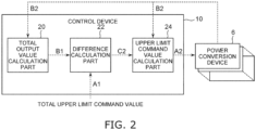
- the control device 10 includes a total output value calculation part 20, a difference calculation part 22, and an upper limit command value calculation part 24.
- the total output value calculation part 20 receives the input of an active power value B2 indicating the magnitude of the currently-outputtable active power for each of the multiple power conversion devices 6.
- the control device 10 receives the input of the active power values B2 from the multiple power conversion devices 6 by communicating with the multiple power conversion devices 6.
- the multiple active power values B2 of the multiple power conversion devices 6 may be input to the control device 10 from a higher-level controller, etc.
- the method for inputting the multiple active power values B2 to the control device 10 is not limited to that described above and may be any method that can appropriately input the multiple active power values B2 to the control device 10.
- the total active power value B1 is the sum total of the active power values B2 of the multiple power conversion devices 6.
- the total output value calculation part 20 inputs the calculated total active power value B1 to the difference calculation part 22.
- the upper limit command value calculation part 24 determines whether or not the multiple individual upper limit command values A2 are greater than designated parameters E1 of the multiple power conversion devices 6.
- the total upper limit command value A1 is greater than the total active power value B1 when the difference C1 and the differences C2 have positive values and the individual upper limit command values A2 are greater than the active power values B2.
- the designated parameters E1 are, for example, the rated outputs (the maximum values of the outputtable active power) of the power conversion devices 6.
- the upper limit command value calculation part 24 corrects the total upper limit command value A1 by subtracting the value of the individual upper limit command value A2 (the value of the parameter E1) of the power conversion device 6 from the total upper limit command value A1 and calculates a total upper limit command value A3 after correction.
- the upper limit command value calculation part 24 determines whether or not the multiple individual upper limit command values A2 are less than 0 after the multiple individual upper limit command values A2 corresponding respectively to the multiple power conversion devices 6 are calculated. In other words, the total upper limit command value A1 is less than the total active power value B1 when the difference C1 and the difference C2 have negative values and the individual upper limit command values A2 are less than the active power values B2.
- the upper limit command value calculation part 24 repeats the processing described above until all of the multiple individual upper limit command values A2 of the multiple power conversion devices 6 are not less than 0.
- the undesirable setting of the individual upper limit command value A2 of the designated power conversion device 6 to be a value less than 0 is suppressed thereby, and the amount of the output of the power conversion device 6 can be appropriately apportioned to another power conversion device 6.
- the control device 10 controls the operations of the multiple power conversion devices 6 so that the active power output from each of the multiple power conversion devices 6 does not exceed the corresponding individual upper limit command value A2. Accordingly, active power having the appropriate magnitude corresponding to the total upper limit command value A1 can be supplied from the solar power generation system 2 to the power system PS.
- control device 10 inputs the calculated multiple individual upper limit command values A2 to the corresponding multiple power conversion devices 6 to control the operations of the multiple power conversion devices 6 so that the active power output from the multiple power conversion devices 6 does not exceed the corresponding individual upper limit command values A2.
- control device 10 may control the operations of the multiple power conversion devices 6 so that the active power output from each of the multiple power conversion devices 6 does not exceed the corresponding individual upper limit command value A2 by generating control signals corresponding to the individual upper limit command values A2 and by inputting the control signals to the power conversion devices 6.
- the control device 10 may directly input the individual upper limit command values A2 to the power conversion devices 6 or may input other control signals corresponding to the individual upper limit command values A2, etc., to the power conversion devices 6.
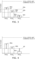
- FIG. 4 is a graph schematically illustrating an example of an operation of a reference control device.
- FIGS. 3 and 4 are bar charts illustrating the active power value B2 of the first power conversion device 6 (PCS 1 ) as B2a, the active power value B2 of the second power conversion device 6 (PCS 2 ) as B2b, and the active power value B2 of the /Vth power conversion device 6 (PCS n ) as B2n.
- FIG. 3 schematically illustrates an example in which, as described above, an individual upper limit command value A2a of the first power conversion device 6 is calculated by adding the difference C2 to the active power value B2a; an individual upper limit command value A2b of the second power conversion device 6 is calculated by adding the difference C2 to the active power value B2b; and an individual upper limit command value A2n of the /Vth power conversion device 6 is calculated by adding the difference C2 to the active power value B2n.
- FIG. 4 schematically illustrates an example of an operation of the reference control device when a common upper limit command value AD for the multiple power conversion devices 6 is set by dividing the total upper limit command value A1 by the number N of the multiple power conversion devices 6.
- the outputs of the first power conversion device 6 and the second power conversion device 6 are undesirably limited to the upper limit command value A0.
- the output of the /Vth power conversion device 6 is less than the upper limit command value A0. Therefore, in the example illustrated in FIG. 4 , for example, the output of the entire system is undesirably less than the total upper limit command value A1 by the amount of the difference between the upper limit command value A0 and the active power value B2n of the /Vth power conversion device 6.
- the output of the entire system is undesirably less than the total upper limit command value A1 despite the ample margin in the outputs of the first power conversion device 6 and the second power conversion device 6.
- the total upper limit command value A1 that is less than the total active power value B1 may be set, and when the solar radiation of the multiple solar cell panels 4 has bias, etc., the total value of the active power of the AC power supplied from the multiple power conversion devices 6 to the power system PS may be undesirably limited more than necessary.
- control device 10 of the solar power generation system 2 calculates the individual upper limit command values A2 of the multiple power conversion devices 6 by adding the difference C2 to the active power values B2 of the multiple power conversion devices 6.
- the individual upper limit command value A2 having the appropriate magnitude corresponding to each active power value B2 can be set for each of the multiple power conversion devices 6 even when the active power values B2 of the multiple power conversion devices 6 have bias.
- the total upper limit command value A1 can be appropriately apportioned to the multiple power conversion devices 6.
- the total value of the active power of the AC power supplied from the multiple power conversion devices 6 to the power system PS can approach the total upper limit command value A1.
- unutilized generated power can be suppressed thereby.
- a reduction of the electricity sales income of the solar power generation system 2 business can be suppressed.
Landscapes
- Engineering & Computer Science (AREA)
- Power Engineering (AREA)
- Supply And Distribution Of Alternating Current (AREA)
Abstract
Description
- Embodiments described herein relate generally to a solar power generation system and a control device.
- A known solar power generation system includes multiple solar cell panels, multiple power conversion devices, and a control device. The multiple power conversion devices are provided to correspond respectively to the multiple solar cell panels. The power conversion devices are connected to the solar cell panels and connected to a power system. The power conversion devices convert DC power supplied from the solar cell panels into AC power corresponding to the power system and supply, to the power system, the AC power after the conversion. The control device controls the conversion operations of the power of the multiple power conversion devices.
- In a solar power generation system, the upper limit of the active power outputtable to the power system is predetermined to suppress fluctuation of the frequency and/or voltage of the power system. The control device controls the operations of the multiple power conversion devices so that the total value of the active power of the AC power output from the multiple power conversion devices does not exceed the upper limit.
- The control device calculates the individual upper limit of each of the multiple power conversion devices by dividing the upper limit of the active power of the entire system by the number of the multiple power conversion devices, and sets the active power of the AC power of each of the multiple power conversion devices to be not more than the individual upper limit. Accordingly, the total value of the active power of the AC power output from the multiple power conversion devices can be set to be not more than the upper limit of the active power of the entire system.
- When, however, the individual upper limit of each of the multiple power conversion devices is set as described above, the total value of the active power of the AC power supplied from the multiple power conversion devices to the power system is undesirably limited more than necessary when, for example, an upper limit that is less than the rated output of the system is set, the solar radiation of the multiple solar cell panels has bias, etc.
- If, for example, there are two power conversion devices, and the upper limit of the active power of the entire system is 10 kW, in such a case, the individual upper limit would be set to 5 kW in the calculation method described above. Then, if the active power outputtable by one power conversion device is 6 kW and the active power outputtable by the other power conversion device is 4 kW, the active power of the one power conversion device would be undesirably limited by the individual upper limit from 6 kW to 5 kW, resulting in an output to the power system of a total of only 9 kW of active power even though 10 kW of active power is outputtable as the entire system.
- Thus, when the individual upper limits are calculated as described above, the total value of the active power of the AC power supplied from the multiple power conversion devices to the power system may be limited more than necessary. For example, generated power is unutilized. Also, in a solar power generation system business, for example, this would lead to lower electricity sales income.
- It is therefore desirable for a solar power generation system and a control device used in a solar power generation system to be able to suppress excessive limitation of the total value of the active power of the AC power supplied from the multiple power conversion devices to the power system.
- [Patent Document 1]
JP-A-2013-207862 - Embodiments of the invention provide a solar power generation system and a control device in which unnecessary limitation of the total value of the active power of the AC power supplied from the multiple power conversion devices to the power system can be suppressed.
- A solar power generation system provided according to an embodiment of the invention includes a plurality of solar cell panels, a plurality of power conversion devices, and a control device; the plurality of power conversion devices is provided to correspond respectively to the plurality of solar cell panels, the plurality of power conversion devices convert direct current power supplied from the plurality of solar cell panels into alternating current power corresponding to a power system, the plurality of power conversion devices supply, to the power system, the alternating current power after the conversion; the control device controls conversion operations of power of the plurality of power conversion devices, the control device includes a total output value calculation part, a difference calculation part, and an upper limit command value calculation part, the total output value calculation part is configured to receive an input of an active power value indicating a magnitude of currently-outputtable active power for each of the plurality of power conversion devices, and calculate a total active power value by summing the active power values of the plurality of power conversion devices, the total active power value indicates a magnitude of currently-outputtable active power from all of the plurality of power conversion devices, the difference calculation part is configured to receive an input of the total active power value, receive an input of a total upper limit command value indicating an upper limit of active power output from all of the plurality of power conversion devices, calculate a difference between the total upper limit command value and the total active power value, and calculate a difference per device of the plurality of power conversion devices by dividing the difference by a number of the plurality of power conversion devices, and the upper limit command value calculation part is configured to receive an input of the difference per device, receive an input of the active power values of the plurality of power conversion devices, and calculate individual upper limit command values by adding the difference per device to the active power values of the plurality of power conversion devices, the individual upper limit command values indicates upper limits of the active power individually output respectively from the plurality of power conversion devices, the control device controls an operation of each of the plurality of power conversion devices so that the active power output from each of the plurality of power conversion devices does not exceed the corresponding individual upper limit command value.
- According to embodiments of the invention, a solar power generation system and a control device are provided in which unnecessary limitation of the total value of the active power of the AC power supplied from the multiple power conversion devices to the power system can be suppressed.
-
- [
Fig. 1 ]
FIG. 1 is a block diagram schematically illustrating a solar power generation system according to an embodiment. - [
Fig. 2 ]
FIG. 2 is a block diagram schematically illustrating the control device according to the embodiment. - [
Fig. 3 ]
FIG. 3 is a graph schematically illustrating an example of an operation of the control device according to the embodiment. - [
Fig. 4 ]
FIG. 4 is a graph schematically illustrating an example of an operation of a reference control device. - Embodiments will now be described with reference to the drawings.
- The drawings are schematic and conceptual; and the relationships between the thicknesses and widths of portions, the proportions of sizes among portions, etc., are not necessarily the same as the actual values. Also, the dimensions and proportions may be illustrated differently among drawings, even for identical portions.
- In the specification and drawings, components similar to those described previously or illustrated in an antecedent drawing are marked with the same reference numerals; and a detailed description is omitted as appropriate.
-
FIG. 1 is a block diagram schematically illustrating a solar power generation system according to an embodiment. - As illustrated in
FIG. 1 , the solar power generation system 2 includes multiplesolar cell panels 4, multiplepower conversion devices 6, and acontrol device 10. The multiplesolar cell panels 4 supply DC power by converting light energy into electrical energy by photoelectric conversion. - The multiple
power conversion devices 6 are provided to correspond respectively to the multiplesolar cell panels 4. The number of the multiplepower conversion devices 6 is, for example, equal to the number of the multiplesolar cell panels 4. The multiplepower conversion devices 6 are connected respectively to the multiplesolar cell panels 4. However, multiplesolar cell panels 4 may be connected to onepower conversion device 6. The number of the multiplepower conversion devices 6 may not always be equal to the number of the multiplesolar cell panels 4. - The solar power generation system 2 further includes, for example,
multiple transformers 12 and atransformer 14. Themultiple transformers 12 are provided to correspond respectively to the multiplepower conversion devices 6. The multiplepower conversion devices 6 are connected to the primary sides of themultiple transformers 12. The secondary sides of themultiple transformers 12 are connected to the primary side of thetransformer 14. The secondary side of thetransformer 14 is connected to a power system PS. The multiplepower conversion devices 6 are connected with the power system PS via thetransformers power conversion devices 6. The configuration between the power system PS and thepower conversion devices 6 may be any configuration that can connect thepower conversion devices 6 to the power system PS. - The power of the power system PS is AC power. The power of the power system PS is, for example, three-phase AC power. However, the power of the power system PS may be single-phase AC power, etc.
- The multiple
power conversion devices 6 convert DC power supplied from the multiplesolar cell panels 4 into AC power corresponding to the power system PS and supply, to the power system PS, the AC power after the conversion. The multiplepower conversion devices 6 include, for example, multiple switching elements and convert the power by switching the multiple switching elements. - The
control device 10 controls the conversion operations of the power of the multiplepower conversion devices 6. Accordingly, the solar power generation system 2 supplies the power generated by the multiplesolar cell panels 4 to the power system PS. - The solar power generation system 2 further includes, for example, a
measurement device 16. For example, themeasurement device 16 detects the active power value, the reactive power value, and the voltage value at the connection point between the power system PS and the multiplepower conversion devices 6 and inputs the active power value, the reactive power value, and the voltage value that are detected to thecontrol device 10. -
FIG. 2 is a block diagram schematically illustrating the control device according to the embodiment. - As illustrated in
FIG. 2 , thecontrol device 10 includes a total outputvalue calculation part 20, adifference calculation part 22, and an upper limit commandvalue calculation part 24. - The total output
value calculation part 20 receives the input of an active power value B2 indicating the magnitude of the currently-outputtable active power for each of the multiplepower conversion devices 6. For example, thecontrol device 10 receives the input of the active power values B2 from the multiplepower conversion devices 6 by communicating with the multiplepower conversion devices 6. For example, the multiple active power values B2 of the multiplepower conversion devices 6 may be input to thecontrol device 10 from a higher-level controller, etc. The method for inputting the multiple active power values B2 to thecontrol device 10 is not limited to that described above and may be any method that can appropriately input the multiple active power values B2 to thecontrol device 10. - The total output
value calculation part 20 calculates a total active power value B1 indicating the magnitude of the currently-outputtable active power from all of the multiplepower conversion devices 6 by summing the active power values B2 of the multiplepower conversion devices 6. - More specifically, the total output
value calculation part 20 calculates the total active power value B1 using the formula 81 = B2a + B2b + ... + 82n, wherein N is the number of the multiplepower conversion devices 6, B2a is the active power value B2 of the firstpower conversion device 6, B2b is the active power value B2 of the secondpower conversion device 6, and 82n is the active power value B2 of the /Vthpower conversion device 6. In other words, the total active power value B1 is the sum total of the active power values B2 of the multiplepower conversion devices 6. The total outputvalue calculation part 20 inputs the calculated total active power value B1 to thedifference calculation part 22. - The
difference calculation part 22 receives the input of the total active power value B1 from the total outputvalue calculation part 20 and receives the input of a total upper limit command value A1 indicating the upper limit of the active power output from all of the multiplepower conversion devices 6. In other words, the total upper limit command value A1 is a command value indicating the upper limit of the active power supplied from the solar power generation system 2 to the power system PS. For example, the total upper limit command value A1 is input to thecontrol device 10 from a higher-level controller, etc. For example, the total upper limit command value A1 may be input to thecontrol device 10 based on an operation of a manager of the solar power generation system 2, etc. The total upper limit command value A1 may be, for example, a preset constant value. The method for inputting the total upper limit command value A1 to thecontrol device 10 is not limited to that described above and may be any method that can appropriately input the total upper limit command value A1 to thecontrol device 10. - The
difference calculation part 22 calculates a difference C1 between the total upper limit command value A1 and the total active power value B1 by subtracting the total active power value B1 from the total upper limit command value A1 that is input. In other words, thedifference calculation part 22 calculates the difference C1 using the formula C1 = A1 - 81. - After the difference C1 is calculated, the
difference calculation part 22 calculates a difference C2 per device of the multiplepower conversion devices 6 by dividing the difference C1 by the number N of the multiplepower conversion devices 6. In other words, thedifference calculation part 22 calculates the difference C2 using the formula C2 = C1/N. Thedifference calculation part 22 inputs the calculated difference C2 to the upper limit commandvalue calculation part 24. In such a case, the number N of the multiplepower conversion devices 6 is, more specifically, the number of thepower conversion devices 6 currently operating among the multiplepower conversion devices 6. - The upper limit command
value calculation part 24 receives the input of the difference C2 from thedifference calculation part 22 and receives the input of the active power values B2 of the multiplepower conversion devices 6. As with the total outputvalue calculation part 20, the multiple active power values B2 are input from the multiplepower conversion devices 6, etc., to the upper limit commandvalue calculation part 24. - The upper limit command
value calculation part 24 calculates individual upper limit command values A2 indicating the upper limit of the active power individually output from each of the multiplepower conversion devices 6 by adding the difference C2 to the active power values B2 of the multiplepower conversion devices 6. Namely, the upper limit commandvalue calculation part 24 calculates the individual upper limit command value A2 using the formula A2 = B2 + C2. - When the total upper limit command value A1 is greater than the total active power value B1, after the multiple individual upper limit command values A2 corresponding respectively to the multiple
power conversion devices 6 are calculated, the upper limit commandvalue calculation part 24 determines whether or not the multiple individual upper limit command values A2 are greater than designated parameters E1 of the multiplepower conversion devices 6. In other words, the total upper limit command value A1 is greater than the total active power value B1 when the difference C1 and the differences C2 have positive values and the individual upper limit command values A2 are greater than the active power values B2. The designated parameters E1 are, for example, the rated outputs (the maximum values of the outputtable active power) of thepower conversion devices 6. - When the individual upper limit command value A2 of the designated
power conversion device 6 is determined to be greater than the designated parameter E1 of thepower conversion device 6, the upper limit commandvalue calculation part 24 modifies the value of the individual upper limit command value A2 of thepower conversion device 6 to be the value of the parameter E1. In other words, the upper limit commandvalue calculation part 24 replaces the value of the individual upper limit command value A2 of thepower conversion device 6 with the value of the parameter E1 by setting A2 = E1. - When the value of the individual upper limit command value A2 of the designated
power conversion device 6 is modified to be the value of the parameter E1, the upper limit commandvalue calculation part 24 corrects the total upper limit command value A1 by subtracting the value of the individual upper limit command value A2 (the value of the parameter E1) of thepower conversion device 6 from the total upper limit command value A1 and calculates a total upper limit command value A3 after correction. In other words, the upper limit commandvalue calculation part 24 calculates the total upper limit command value A3 after correction using the formula A3 = A1 - A2. - Also, when the value of the individual upper limit command value A2 of the designated
power conversion device 6 is modified to be the value of the parameter E1, the upper limit commandvalue calculation part 24 corrects the total active power value B1 by subtracting the active power value B2 of thepower conversion device 6 from the total active power value B1 and calculates a total active power value B3 after correction. In other words, the upper limit commandvalue calculation part 24 calculates the total active power value B3 after correction using the formula B3 = B1 - B2. - After the total upper limit command value A3 and the total active power value B3 are calculated, the upper limit command
value calculation part 24 calculates a difference C3 after correction between the total upper limit command value A3 and the total active power value B3 by subtracting the total active power value B3 from the total upper limit command value A3. In other words, the upper limit commandvalue calculation part 24 calculates the difference C3 after correction using the formula C3 = A3 - B3. - Also, the upper limit command
value calculation part 24 calculates a number N' of the remainingpower conversion devices 6 by subtracting, from the number N of the multiplepower conversion devices 6, the number of thepower conversion devices 6 for which the value of the individual upper limit command value A2 was modified to be the value of the parameter E1. - The upper limit command
value calculation part 24 calculates a difference C2' per device of the remainingpower conversion devices 6 by dividing the difference C3 after correction by the number N' of the remainingpower conversion devices 6. In other words, the upper limit commandvalue calculation part 24 calculates the difference C2' using the formula C2' = C3/N'. - After the difference C2' is calculated, the upper limit command
value calculation part 24 recalculates the individual upper limit command value A2 for each of the remainingpower conversion devices 6 by adding the difference C2' to the active power values B2 of the remainingpower conversion devices 6. In other words, the upper limit commandvalue calculation part 24 recalculates the individual upper limit command value A2 using the formula A2 = B2 + C2'. - When the total upper limit command value A1 is greater than the total active power value B1, the upper limit command
value calculation part 24 repeats the processing described above until all of the multiple individual upper limit command values A2 of the multiplepower conversion devices 6 are not more than the designated parameters E1. The undesirable setting of the individual upper limit command value A2 of the designatedpower conversion device 6 to have a value that is greater than the designated parameter E1 is suppressed thereby, and the amount of the output of thepower conversion device 6 that is greater than the designated parameter E1 can be appropriately apportioned to anotherpower conversion device 6. - On the other hand, when the total upper limit command value A1 is less than the total active power value B1, the upper limit command
value calculation part 24 determines whether or not the multiple individual upper limit command values A2 are less than 0 after the multiple individual upper limit command values A2 corresponding respectively to the multiplepower conversion devices 6 are calculated. In other words, the total upper limit command value A1 is less than the total active power value B1 when the difference C1 and the difference C2 have negative values and the individual upper limit command values A2 are less than the active power values B2. - When the individual upper limit command value A2 of a designated
power conversion device 6 is determined to be less than 0, the upper limit commandvalue calculation part 24 modifies the value of the individual upper limit command value A2 of thepower conversion device 6 to be 0. In other words, the upper limit commandvalue calculation part 24 replaces the value of the individual upper limit command value A2 of thepower conversion device 6 with 0 by setting A2 = 0. - When the value of the individual upper limit command value A2 of the designated
power conversion device 6 is modified to be 0, the upper limit commandvalue calculation part 24 corrects the total active power value B1 by subtracting the active power value B2 of thepower conversion device 6 from the total active power value B1 and calculates the total active power value B3 after correction. In other words, the upper limit commandvalue calculation part 24 calculates the total active power value B3 after correction using the formula B3 = B1 - B2. - After the total active power value B3 is calculated, the upper limit command
value calculation part 24 calculates the difference C3 after correction between the total upper limit command value A1 and the total active power value B3 by subtracting the total active power value B3 from the total upper limit command value A1. In other words, the upper limit commandvalue calculation part 24 calculates the difference C3 after correction using the formula C3 = A1 - B3. - Also, the upper limit command
value calculation part 24 calculates the number N' of the remainingpower conversion devices 6 by subtracting, from the number N of the multiplepower conversion devices 6, the number of thepower conversion devices 6 for which the value of the individual upper limit command value A2 was modified to be 0. - The upper limit command
value calculation part 24 calculates the difference C2' per device of the remainingpower conversion devices 6 by dividing the difference C3 after correction by the number N' of the remainingpower conversion devices 6. In other words, the upper limit commandvalue calculation part 24 calculates the difference C2' using the formula C2' = C3/N'. - After the difference C2' is calculated, the upper limit command
value calculation part 24 recalculates the individual upper limit command value A2 for each of the remainingpower conversion devices 6 by adding the difference C2' to the active power values B2 of the remainingpower conversion devices 6. In other words, the upper limit commandvalue calculation part 24 recalculates the individual upper limit command value A2 using the formula A2 = B2 + C2'. - When the total upper limit command value A1 is less than the total active power value B1, the upper limit command
value calculation part 24 repeats the processing described above until all of the multiple individual upper limit command values A2 of the multiplepower conversion devices 6 are not less than 0. The undesirable setting of the individual upper limit command value A2 of the designatedpower conversion device 6 to be a value less than 0 is suppressed thereby, and the amount of the output of thepower conversion device 6 can be appropriately apportioned to anotherpower conversion device 6. - After the multiple individual upper limit command values A2 are calculated to be not more than the designated parameters E1 and not less than 0, the
control device 10 controls the operations of the multiplepower conversion devices 6 so that the active power output from each of the multiplepower conversion devices 6 does not exceed the corresponding individual upper limit command value A2. Accordingly, active power having the appropriate magnitude corresponding to the total upper limit command value A1 can be supplied from the solar power generation system 2 to the power system PS. - For example, the
control device 10 inputs the calculated multiple individual upper limit command values A2 to the corresponding multiplepower conversion devices 6 to control the operations of the multiplepower conversion devices 6 so that the active power output from the multiplepower conversion devices 6 does not exceed the corresponding individual upper limit command values A2. - The control is not limited thereto; for example, the
control device 10 may control the operations of the multiplepower conversion devices 6 so that the active power output from each of the multiplepower conversion devices 6 does not exceed the corresponding individual upper limit command value A2 by generating control signals corresponding to the individual upper limit command values A2 and by inputting the control signals to thepower conversion devices 6. Thecontrol device 10 may directly input the individual upper limit command values A2 to thepower conversion devices 6 or may input other control signals corresponding to the individual upper limit command values A2, etc., to thepower conversion devices 6. -
FIG. 3 is a graph schematically illustrating an example of an operation of the control device according to the embodiment. -
FIG. 4 is a graph schematically illustrating an example of an operation of a reference control device. -
FIGS. 3 and 4 are bar charts illustrating the active power value B2 of the first power conversion device 6 (PCS1) as B2a, the active power value B2 of the second power conversion device 6 (PCS2) as B2b, and the active power value B2 of the /Vth power conversion device 6 (PCSn) as B2n. -
FIG. 3 schematically illustrates an example in which, as described above, an individual upper limit command value A2a of the firstpower conversion device 6 is calculated by adding the difference C2 to the active power value B2a; an individual upper limit command value A2b of the secondpower conversion device 6 is calculated by adding the difference C2 to the active power value B2b; and an individual upper limit command value A2n of the /Vthpower conversion device 6 is calculated by adding the difference C2 to the active power value B2n. -
FIG. 4 schematically illustrates an example of an operation of the reference control device when a common upper limit command value AD for the multiplepower conversion devices 6 is set by dividing the total upper limit command value A1 by the number N of the multiplepower conversion devices 6. - In the example illustrated in
FIG. 4 , the outputs of the firstpower conversion device 6 and the secondpower conversion device 6 are undesirably limited to the upper limit command value A0. On the other hand, in the example illustrated inFIG. 4 , the output of the /Vthpower conversion device 6 is less than the upper limit command value A0. Therefore, in the example illustrated inFIG. 4 , for example, the output of the entire system is undesirably less than the total upper limit command value A1 by the amount of the difference between the upper limit command value A0 and the active power value B2n of the /Vthpower conversion device 6. In the example illustrated inFIG. 4 , the output of the entire system is undesirably less than the total upper limit command value A1 despite the ample margin in the outputs of the firstpower conversion device 6 and the secondpower conversion device 6. - Thus, when the common upper limit command value A0 is set for the multiple
power conversion devices 6, the total upper limit command value A1 that is less than the total active power value B1 may be set, and when the solar radiation of the multiplesolar cell panels 4 has bias, etc., the total value of the active power of the AC power supplied from the multiplepower conversion devices 6 to the power system PS may be undesirably limited more than necessary. - In contrast, the
control device 10 of the solar power generation system 2 according to the embodiment calculates the individual upper limit command values A2 of the multiplepower conversion devices 6 by adding the difference C2 to the active power values B2 of the multiplepower conversion devices 6. - Accordingly, for example, as illustrated in
FIG. 3 , the individual upper limit command value A2 having the appropriate magnitude corresponding to each active power value B2 can be set for each of the multiplepower conversion devices 6 even when the active power values B2 of the multiplepower conversion devices 6 have bias. In other words, the total upper limit command value A1 can be appropriately apportioned to the multiplepower conversion devices 6. - Accordingly, even when the total upper limit command value A1 that is less than the total active power value B1 is set and the solar radiation of the multiple
solar cell panels 4 has bias, etc., the excessive limitation of the total value of the active power of the AC power supplied from the multiplepower conversion devices 6 to the power system PS can be suppressed. - For example, compared to when the common upper limit command value A0 is set for the multiple
power conversion devices 6, the total value of the active power of the AC power supplied from the multiplepower conversion devices 6 to the power system PS can approach the total upper limit command value A1. For example, unutilized generated power can be suppressed thereby. Also, for example, a reduction of the electricity sales income of the solar power generation system 2 business can be suppressed. - Although several embodiments of the invention are described, these embodiments are presented as examples and are not intended to limit the scope of the invention. These novel embodiments may be carried out in other various forms; and various omissions, substitutions, and modifications can be performed without departing from the spirit of the invention. Such embodiments and their modifications are within the scope and spirit of the invention and are included in the invention described in the claims and their equivalents.
- 2 solar power generation system, 4 solar cell panel, 6 power conversion device, 10 control device, 12, 14 transformers, 20 total output value calculation part, 22 difference calculation part, 24 upper limit command value calculation part
Claims (6)
- A solar power generation system, comprising:a plurality of solar cell panels;a plurality of power conversion devices provided to correspond respectively to the plurality of solar cell panels, the plurality of power conversion devices converting direct current power supplied from the plurality of solar cell panels into alternating current power corresponding to a power system, the plurality of power conversion devices supplying, to the power system, the alternating current power after the conversion; anda control device controlling conversion operations of power of the plurality of power conversion devices,the control device includinga total output value calculation part thatreceives an input of an active power value indicating a magnitude of currently-outputtable active power for each of the plurality of power conversion devices, andcalculates a total active power value by summing the active power values of the plurality of power conversion devices, the total active power value indicating a magnitude of currently-outputtable active power from all of the plurality of power conversion devices,a difference calculation part thatreceives an input of the total active power value,receives an input of a total upper limit command value indicating an upper limit of active power output from all of the plurality of power conversion devices,calculates a difference between the total upper limit command value and the total active power value, andcalculates a difference per device of the plurality of power conversion devices by dividing the difference by a number of the plurality of power conversion devices, andan upper limit command value calculation part thatreceives an input of the difference per device,receives an input of the active power values of the plurality of power conversion devices, andcalculates individual upper limit command values by adding the difference per device to the active power values of the plurality of power conversion devices, the individual upper limit command values indicating upper limits of the active power individually output respectively from the plurality of power conversion devices,the control device controlling an operation of each of the plurality of power conversion devices so that the active power output from each of the plurality of power conversion devices does not exceed the corresponding individual upper limit command value.
- The solar power generation system according to claim 1, wherein
when the individual upper limit command value of a designated power conversion device among the plurality of power conversion devices is greater than a designated parameter of the designated power conversion device, the upper limit command value calculation part modifies a value of the individual upper limit command value of the designated power conversion device to be a value of the designated parameter. - The solar power generation system according to claim 2, wherein
when the value of the individual upper limit command value of the designated power conversion device is modified to be the value of the designated parameter, the upper limit command value calculation part:calculates a total upper limit command value after correction by subtracting the value of the individual upper limit command value of the designated power conversion device from the total upper limit command value;calculates a total active power value after correction by subtracting the active power value of the designated power conversion device from the total active power value;calculates a difference after correction between the total upper limit command value after correction and the total active power value after correction;calculates a number of remaining power conversion devices by subtracting, from the number of the plurality of power conversion devices, a number of the power conversion devices for which the value of the individual upper limit command value was modified to be the value of the designated parameter,calculates a difference per device of the remaining power conversion devices by dividing the difference after correction by the number of the remaining power conversion devices, andrecalculates the individual upper limit command value for each of the remaining power conversion devices by adding the difference per device of the remaining power conversion devices to the active power value of each of the remaining power conversion devices. - The solar power generation system according to claim 1, wherein
when the individual upper limit command value of a designated power conversion device among the plurality of power conversion devices is less than 0, the upper limit command value calculation part modifies a value of the individual upper limit command value of the designated power conversion device to be 0. - The solar power generation system according to claim 4, wherein
when the value of the individual upper limit command value of the designated power conversion device is modified to be 0, the upper limit command value calculation part:calculates a total active power value after correction by subtracting the active power value of the designated power conversion device from the total active power value;calculates a difference after correction between the total upper limit command value and the total active power value after correction;calculates a number of remaining power conversion devices by subtracting, from the number of the plurality of power conversion devices, a number of the power conversion devices for which the value of the individual upper limit command value was modified to be 0;calculates a difference per device of the remaining power conversion devices by dividing the difference after correction by the number of the remaining power conversion devices; andrecalculates the individual upper limit command value for each of the remaining power conversion devices by adding the difference per device of the remaining power conversion devices to the active power value of each of the remaining power conversion devices. - A control device controlling conversion operations of power of a plurality of power conversion devices, the plurality of power conversion devices being provided to correspond respectively to a plurality of solar cell panels, the plurality of power conversion devices converting direct current power supplied from the plurality of solar cell panels into alternating current power corresponding to a power system, the plurality of power conversion devices supplying, to the power system, the alternating current power after the conversion, the control device comprising:a total output value calculation part thatreceives an input of an active power value indicating a magnitude of currently-outputtable active power for each of the plurality of power conversion devices, andcalculates a total active power value by summing the active power values of the plurality of power conversion devices, the total active power value indicating a magnitude of currently-outputtable active power from all of the plurality of power conversion devices;a difference calculation part thatreceives an input of the total active power value,receives an input of a total upper limit command value indicating an upper limit of active power output from all of the plurality of power conversion devices,calculates a difference between the total upper limit command value and the total active power value, andcalculates a difference per device of the plurality of power conversion devices by dividing the difference by a number of the plurality of power conversion devices; andan upper limit command value calculation part thatreceives an input of the difference per device,receives an input of the active power values of the plurality of power conversion devices, andcalculates individual upper limit command values by adding the difference per device to the active power values of the plurality of power conversion devices, the individual upper limit command values indicating upper limits of the active power individually output respectively from the plurality of power conversion devices,the control device controlling an operation of each of the plurality of power conversion devices so that the active power output from each of the plurality of power conversion devices does not exceed the corresponding individual upper limit command value.
Applications Claiming Priority (1)
| Application Number | Priority Date | Filing Date | Title |
|---|---|---|---|
| PCT/JP2022/008289 WO2023162222A1 (en) | 2022-02-28 | 2022-02-28 | Photovoltaic power generating system and control device |
Publications (2)
| Publication Number | Publication Date |
|---|---|
| EP4489250A1 true EP4489250A1 (en) | 2025-01-08 |
| EP4489250A4 EP4489250A4 (en) | 2026-01-14 |
Family
ID=87765164
Family Applications (1)
| Application Number | Title | Priority Date | Filing Date |
|---|---|---|---|
| EP22928748.7A Pending EP4489250A4 (en) | 2022-02-28 | 2022-02-28 | PHOTOVOLTAIC POWER GENERATION SYSTEM AND CONTROL DEVICE |
Country Status (4)
| Country | Link |
|---|---|
| US (1) | US12323095B2 (en) |
| EP (1) | EP4489250A4 (en) |
| JP (1) | JP7565473B2 (en) |
| WO (1) | WO2023162222A1 (en) |
Family Cites Families (7)
| Publication number | Priority date | Publication date | Assignee | Title |
|---|---|---|---|---|
| CN102906951B (en) * | 2009-10-02 | 2015-11-25 | 松下电器产业株式会社 | Power distribution equipment and use the distribution system of this power distribution equipment |
| JP2013126260A (en) * | 2011-12-13 | 2013-06-24 | Hokkaido Electric Power Co Inc:The | Operation apparatus and method of natural variation power supply |
| JP5980536B2 (en) | 2012-03-27 | 2016-08-31 | シャープ株式会社 | Power generation system, and power conditioner and output suppression management device used in the power generation system |
| JP6161730B2 (en) * | 2014-01-20 | 2017-07-12 | 三菱電機株式会社 | Power converter |
| JP2017118721A (en) * | 2015-12-25 | 2017-06-29 | 株式会社ノーリツ | Power generation system |
| AU2017226244B2 (en) * | 2016-03-02 | 2021-12-09 | Daihen Corporation | Electric power system |
| JP7098867B2 (en) * | 2018-09-07 | 2022-07-12 | 株式会社ダイヘン | Power system and processing equipment |
-
2022
- 2022-02-28 US US18/555,547 patent/US12323095B2/en active Active
- 2022-02-28 EP EP22928748.7A patent/EP4489250A4/en active Pending
- 2022-02-28 JP JP2024502742A patent/JP7565473B2/en active Active
- 2022-02-28 WO PCT/JP2022/008289 patent/WO2023162222A1/en not_active Ceased
Also Published As
| Publication number | Publication date |
|---|---|
| JPWO2023162222A1 (en) | 2023-08-31 |
| WO2023162222A1 (en) | 2023-08-31 |
| JP7565473B2 (en) | 2024-10-10 |
| EP4489250A4 (en) | 2026-01-14 |
| US20240204720A1 (en) | 2024-06-20 |
| US12323095B2 (en) | 2025-06-03 |
Similar Documents
| Publication | Publication Date | Title |
|---|---|---|
| US9287418B2 (en) | System and method for connection of photovoltaic arrays in series and parallel arrangements | |
| EP2114002B1 (en) | 3-phase power conversion device | |
| EP0762624A2 (en) | Control system for power converter system | |
| EP2469372A2 (en) | Methods and systems for operating a two-stage power converter | |
| EP3764504B1 (en) | Method for controlling string inverter, controller, inverter, and inverter system | |
| EP2469680A2 (en) | Power conversion system and method | |
| EP3979492B1 (en) | Electric energy backward-flow control method, converter, and photovoltaic power generation system | |
| CN115485968B (en) | Photovoltaic power generation system, power control method and combiner box | |
| Irmak et al. | A modified droop control method for PV systems in island mode DC microgrid | |
| EP3855595B1 (en) | Photovoltaic system | |
| EP3780308B1 (en) | Inverter, power generation system, and method for inhibiting the distortion of harmonic waves | |
| EP4138251B1 (en) | Power supply system | |
| US12323095B2 (en) | Solar power generation system and control device | |
| EP4482014A1 (en) | Power supply system for autonomous system | |
| CN103050879A (en) | Multiplexed output self current-balancing power supply control circuit | |
| CN109804557B (en) | Solar power generation system | |
| US20260142472A1 (en) | Solar power generation system and control device | |
| WO2021205701A1 (en) | Power conversion device | |
| US20240079880A1 (en) | Inverter with Scalable DC/DC Voltage Boost Converter | |
| EP4277075B9 (en) | Photovoltaic system and power supply current control method therefor | |
| TWI505597B (en) | Intelligent microgrid power quality management operating system | |
| Aryan et al. | Distributed primary and secondary control strategy for power sharing and voltage restoration in a DC microgrid | |
| JPWO2019049380A1 (en) | Power generation system | |
| WO2025017803A1 (en) | Photovoltaic power generation system and control device | |
| KR20160080719A (en) | Apparatus for controlling power configured to be connected to power system operating temporarily and method for controlling power |
Legal Events
| Date | Code | Title | Description |
|---|---|---|---|
| STAA | Information on the status of an ep patent application or granted ep patent |
Free format text: STATUS: THE INTERNATIONAL PUBLICATION HAS BEEN MADE |
|
| PUAI | Public reference made under article 153(3) epc to a published international application that has entered the european phase |
Free format text: ORIGINAL CODE: 0009012 |
|
| STAA | Information on the status of an ep patent application or granted ep patent |
Free format text: STATUS: REQUEST FOR EXAMINATION WAS MADE |
|
| 17P | Request for examination filed |
Effective date: 20231005 |
|
| AK | Designated contracting states |
Kind code of ref document: A1 Designated state(s): AL AT BE BG CH CY CZ DE DK EE ES FI FR GB GR HR HU IE IS IT LI LT LU LV MC MK MT NL NO PL PT RO RS SE SI SK SM TR |
|
| DAV | Request for validation of the european patent (deleted) | ||
| DAX | Request for extension of the european patent (deleted) | ||
| A4 | Supplementary search report drawn up and despatched |
Effective date: 20251211 |
|
| RIC1 | Information provided on ipc code assigned before grant |
Ipc: H02J 3/38 20060101AFI20251205BHEP Ipc: H02J 3/46 20060101ALI20251205BHEP Ipc: H02S 40/32 20140101ALI20251205BHEP Ipc: H02S 50/00 20140101ALI20251205BHEP |