EP4489221A1 - Antenna and antenna arrangement for a motor vehicle, motor vehicle and method for manufacturing an antenna - Google Patents
Antenna and antenna arrangement for a motor vehicle, motor vehicle and method for manufacturing an antenna Download PDFInfo
- Publication number
- EP4489221A1 EP4489221A1 EP23183432.6A EP23183432A EP4489221A1 EP 4489221 A1 EP4489221 A1 EP 4489221A1 EP 23183432 A EP23183432 A EP 23183432A EP 4489221 A1 EP4489221 A1 EP 4489221A1
- Authority
- EP
- European Patent Office
- Prior art keywords
- antenna
- motor vehicle
- metal layer
- plastic part
- target region
- Prior art date
- Legal status (The legal status is an assumption and is not a legal conclusion. Google has not performed a legal analysis and makes no representation as to the accuracy of the status listed.)
- Pending
Links
Images


Classifications
-
- H—ELECTRICITY
- H01—ELECTRIC ELEMENTS
- H01Q—ANTENNAS, i.e. RADIO AERIALS
- H01Q1/00—Details of, or arrangements associated with, antennas
- H01Q1/27—Adaptation for use in or on movable bodies
- H01Q1/32—Adaptation for use in or on road or rail vehicles
- H01Q1/325—Adaptation for use in or on road or rail vehicles characterised by the location of the antenna on the vehicle
- H01Q1/3283—Adaptation for use in or on road or rail vehicles characterised by the location of the antenna on the vehicle side-mounted antennas, e.g. bumper-mounted, door-mounted
-
- H—ELECTRICITY
- H01—ELECTRIC ELEMENTS
- H01Q—ANTENNAS, i.e. RADIO AERIALS
- H01Q1/00—Details of, or arrangements associated with, antennas
- H01Q1/27—Adaptation for use in or on movable bodies
- H01Q1/32—Adaptation for use in or on road or rail vehicles
- H01Q1/3208—Adaptation for use in or on road or rail vehicles characterised by the application wherein the antenna is used
- H01Q1/3233—Adaptation for use in or on road or rail vehicles characterised by the application wherein the antenna is used particular used as part of a sensor or in a security system, e.g. for automotive radar, navigation systems
-
- H—ELECTRICITY
- H01—ELECTRIC ELEMENTS
- H01Q—ANTENNAS, i.e. RADIO AERIALS
- H01Q13/00—Waveguide horns or mouths; Slot antennas; Leaky-waveguide antennas; Equivalent structures causing radiation along the transmission path of a guided wave
- H01Q13/02—Waveguide horns
-
- H—ELECTRICITY
- H01—ELECTRIC ELEMENTS
- H01Q—ANTENNAS, i.e. RADIO AERIALS
- H01Q21/00—Antenna arrays or systems
- H01Q21/0006—Particular feeding systems
- H01Q21/0037—Particular feeding systems linear waveguide fed arrays
- H01Q21/0043—Slotted waveguides
Definitions
- the present invention is directed to an antenna for a motor vehicle, the antenna comprising a waveguide component with a target region for positioning a receiver and/or transmitter device.
- the invention is further directed to an antenna arrangement for a motor vehicle comprising such an antenna, to a motor vehicle comprising such an antenna arrangement and to a method for manufacturing an antenna.
- Antennas are used in motor vehicles for transmitting and/or receiving electromagnetic waves, for example for communication purposes or for environmental perception, for example by means of radar systems.
- Radar systems are used for various applications in motor vehicles, in particular for realizing driver assistance functions or other functions for guiding a vehicle automatically or in part automatically.
- Corresponding radar systems may, for example, comprise waveguide antennas, for example, slotted waveguide antennas or aperture antennas, such as horn antennas.
- the invention is based on the idea to use a waveguide component, which comprises a plastic part, whose inner surface for guiding electromagnetic waves is galvanized or metallized to form a metal layer.
- an antenna for a motor vehicle comprises a waveguide component and a target region for positioning a receiver and/or transmitter device.
- the waveguide component comprises a plastic part, and an inner surface of the plastic part comprises a galvanized metal layer or a metallized metal layer, which is a metal layer made by metallization.
- the inner surface, which comprises the galvanized metal layer is for guiding electromagnetic waves from the target region into an outer environment of the antenna and/or from the outer environment to the target region.
- the antenna is designed as a waveguide antenna, also denoted as waveguide fed antenna.
- the antenna may, for example, be designed as an aperture antenna or as a slotted waveguide antenna or as another antenna with a metal structure.
- the antenna may be a communication antenna and/or a radar antenna, for example.
- That the plastic part comprises the galvanized metal layer may be understood such that the plastic part is partially galvanized at its inner surface.
- the plastic part is a galvanized or partially galvanized plastic part.
- That the plastic part comprises the metallized metal layer may be understood such that the plastic part is partially metallized at its inner surface.
- the plastic part is a metallized or partially metallized plastic part.
- the plastic part is designed to form an enclosure for guiding the electromagnetic waves, wherein the enclosure is open to the environment.
- the inner surface can be understood to face an interior of the enclosure.
- the receiver and/or transmitter device may, for example, comprise a wave source for the electromagnetic waves, in particular for emitting the electromagnetic waves in a predefined frequency band, for example, in the range of several GHz or several tens of GHz, for example, between 10 GHz and 100 GHz or between 20 GHz and 85 GHz.
- the frequency band may be a frequency band as commonly used for automotive radar systems, for example, an automotive long range radar band, also denoted as LRR band, or an automotive short range radar band, also denoted as SRR band.
- LRR band ranges from 76 GHz to 77 GHz
- the SRR band ranges from 77 GHz to 81 GHz, for example.
- the receiver and/or transmitter device may comprise electronic circuitry for detecting and/or processing the electromagnetic waves reaching the receiver and/or transmitter device from the environment of the antenna.
- the antenna can, however, be used with other frequencies as well.
- the waves can be guided properly from the target direction to the environment or vice versa. Since the electromagnetic waves penetrate the surface of the waveguide component only up to the respective penetration depth, which can, for example, be in the order of few micrometers or below one micrometer for the relevant frequency bands, there is no need for providing a waveguide component which is completely or predominantly made of metal. Rather, the plastic part, which provides sufficient mechanical stability of the waveguide component, may be made of various materials, for example by means of injection molding or extrusion, without significantly affecting the guidance of the electromagnetic waves. Consequently, providing the galvanized or metallized plastic part combines the beneficial electromagnetic properties for guiding the electromagnetic waves of the metal layer with low weight and high mechanical stability of the plastic material. In particular, also costs of the antenna may be reduced by using a galvanized or metallized metal layer instead of, for example, a solid metallic part as the waveguide component.
- the thickness of the metal layer is equal to or greater than a penetration depth of a material of the metal layer for a predefined frequency of the electromagnetic waves.
- the thickness of the metal layer may, for example, be less than 100 times the penetration depth or less than 50 times the penetration depth or less than 20 times the penetration depth or less than 10 times the penetration depth.
- the predefined frequency of the electromagnetic waves lies within the range of [10 GHz, 100 GHz].
- the frequency may lie within the range from 21 GHz to 26 GHz corresponding the so-called ultrawide band, UWB, range, within the range from 24 GHz to 24.25 GHz corresponding to the so-called narrow band ISM range, NB-ISM, within the range from 76 GHz to 77 GHz, which corresponds to the automotive LRR band or within the range from 77 GHz to 81 GHz, which corresponds to the automotive SRR band.
- UWB ultrawide band
- NB-ISM narrow band ISM range
- the metal layer is made of silver or a silver alloy or is made of copper or a copper alloy.
- Silver and copper as well as the corresponding alloys are well suitable materials for guiding the electromagnetic waves in the respective relevant frequency ranges.
- it is very beneficia to use a metal with a high electric conductivity.
- the higher the electric conductivity of the used metal the thinner the metal layer can be made, in particular in view of the penetration depth.
- the antenna is an aperture antenna or a travelling wave antenna or a slotted waveguide antenna.
- the antenna comprises the receiver and/or transmitter device, and the receiver and/or transmitter device is arranged and fastened to the target region.
- an antenna arrangement for a motor vehicle comprises an antenna according to the invention and a body part for the motor vehicle.
- the antenna is fastened to the body part.
- the antenna arrangement may for example be a communication antenna arrangement and/or a radar antenna arrangement.
- the antenna of the antenna arrangement is then designed as communication antenna and/or a radar antenna, accordingly.
- the antenna is fastened to the body part by means of a clip connection.
- the plastic part may, for example, comprise features, such as latching lugs, which engage with corresponding features of the body part in order to realize the clip connection.
- the antenna may be fastened to the body part securely in a particularly simple way.
- the body part is a bumper for the motor vehicle or a grille for the motor vehicle.
- a motor vehicle comprises an antenna according to the invention or an antenna arrangement according to the invention.
- a method for manufacturing an antenna according to the invention is provided.
- the waveguide component is provided, and the metal layer is generated by galvanizing or metallizing the inner surface of the plastic part.
- the receiver and/or transmitter device is provided and fastened to the target region.
- the plastic part is produced by injection molding or by an extrusion process.
- the invention also includes further embodiments of the method according to the invention which have features as already described in connection with the further embodiments of the antenna, the antenna arrangement and the motor vehicle according to the invention. Thus, the corresponding further embodiments of the method according to the invention are not described again here.
- the invention also comprises combinations of the features of the described implementations.
- an error message and/or a prompt for user feedback is output and/or a default setting and/or a predetermined initial state is set.
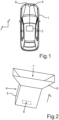
- Fig. 1 shows schematically a motor vehicle 1 with an exemplary implementation of a antenna 4 according to the invention.
- the antenna 4 may, for example, be integrated into a body part 9 of the motor vehicle 1, for example a bumper or grille.
- the motor vehicle 1 may, for example, comprise an electronic control unit 3 or another computing unit for controlling the antenna 4 and/or for receiving data from the antenna 4.
- the antenna 4 is for example a radar antenna.
- the antenna 4 is implemented as a waveguide antenna, for example an aperture antenna, as the horn type aperture antenna shown schematically in Fig. 2 , or a slotted waveguide antenna, as shown in the exemplary implementation schematically in Fig. 8 .
- the antenna 4 comprises a waveguide component 5, which may constitute a housing part of the antenna.
- the waveguide component 5 comprises a plastic part 6, which is partly galvanized or metallized such that a metal layer is formed on an inner surface 7 of the plastic part 6, which guides electromagnetic waves 11 (see Fig. 3 ) from a target region 8 into an outer environment of the antenna 4 and/or from the outer environment to the target region 8.
- a receiver and/or transmitter device 10, in particular a wave source for electromagnetic waves 11 and/or a receiver chip for receiving the electromagnetic waves 11, may be arranged at the target region 8.
- the thickness of the metal layer is, for example, equal to or greater than a penetration depth of the material of the metal layer, for example silver, for a predefined frequency of the electromagnetic waves.
- the penetration depth may in an exemplary use case, for example, be 0.23 micrometers. In general, the penetration depth depends on the frequency of the electromagnetic waves 11.
- the thickness of the metal layer is consequently chosen such that for a predefined reference frequency, which may, for example, lie within the range 10 gigahertz to 100 gigahertz, the thickness is greater than or equal to the penetration depth.
- Fig. 3 shows a top view of an exemplary implementation of the antenna 4 with a wave source chip 10 mounted at the target region 8.
- the waveguide component 5 comprises the plastic part 6 providing mechanical support and the possibility for a simple mounting to the body part 9.
- the electrically relevant part for guiding the electromagnetic waves 11 is constituted by the metal layer on the inner surface 7. Due to the mechanical support by the plastic part 6, the metal layer can be designed very thin.
- Fig. 4 shows the antenna 4 in a front view and Fig. 5 shows the antenna 4 in a side view.
- the plastic part 6 comprises latching lugs 12 on an outer side for mounting the antenna 4 to the body part.
- An exemplary implementation of an antenna arrangement 13 according to the invention with such a antenna 4 is shown in a schematic side view in Fig. 6 and in a corresponding schematic top view in Fig. 7 , where the body part 9 is a grille of the motor vehicle 1.
- a radome (not shown) can be applied to tune the dielectric constant.
- a horn antenna for example 7x1.5x5 mm in a specific non-limiting use case
- a slotted waveguide antenna for example 50x12x20 mm in a specific non-limiting use case
- the invention provides a galvanized or metallized antenna, which may for example be integrated into body parts, in particular plastic body parts, of a motor vehicle.
- the antenna may be used in different frequency bands including radar bands such as LRR and SRR.
- the plastic body parts of the motor vehicle such as grille or bumper, may be manufactured by means of an injection molded process, which allows for very precise dimensions.
Landscapes
- Engineering & Computer Science (AREA)
- Remote Sensing (AREA)
- Computer Security & Cryptography (AREA)
- Radar, Positioning & Navigation (AREA)
- Radar Systems Or Details Thereof (AREA)
Abstract
Description
- The present invention is directed to an antenna for a motor vehicle, the antenna comprising a waveguide component with a target region for positioning a receiver and/or transmitter device. The invention is further directed to an antenna arrangement for a motor vehicle comprising such an antenna, to a motor vehicle comprising such an antenna arrangement and to a method for manufacturing an antenna.
- Antennas are used in motor vehicles for transmitting and/or receiving electromagnetic waves, for example for communication purposes or for environmental perception, for example by means of radar systems. Radar systems are used for various applications in motor vehicles, in particular for realizing driver assistance functions or other functions for guiding a vehicle automatically or in part automatically. Corresponding radar systems may, for example, comprise waveguide antennas, for example, slotted waveguide antennas or aperture antennas, such as horn antennas.
- It is an objective of the present invention to provide an antenna for a motor vehicle, which has a waveguide component with high mechanical stability and low weight.
- This objective is achieved by the respective subject-matter of the independent claims. Further implementations and preferred embodiments are subject-matter of the dependent claims.
- The invention is based on the idea to use a waveguide component, which comprises a plastic part, whose inner surface for guiding electromagnetic waves is galvanized or metallized to form a metal layer.
- According to an aspect of the invention, an antenna for a motor vehicle is provided. The antenna comprises a waveguide component and a target region for positioning a receiver and/or transmitter device. The waveguide component comprises a plastic part, and an inner surface of the plastic part comprises a galvanized metal layer or a metallized metal layer, which is a metal layer made by metallization.
- The inner surface, which comprises the galvanized metal layer is for guiding electromagnetic waves from the target region into an outer environment of the antenna and/or from the outer environment to the target region.
- In other words, the antenna is designed as a waveguide antenna, also denoted as waveguide fed antenna. The antenna may, for example, be designed as an aperture antenna or as a slotted waveguide antenna or as another antenna with a metal structure.
- The antenna may be a communication antenna and/or a radar antenna, for example.
- That the plastic part comprises the galvanized metal layer may be understood such that the plastic part is partially galvanized at its inner surface. In other words, the plastic part is a galvanized or partially galvanized plastic part. That the plastic part comprises the metallized metal layer may be understood such that the plastic part is partially metallized at its inner surface. In other words, the plastic part is a metallized or partially metallized plastic part.
- In particular, the plastic part is designed to form an enclosure for guiding the electromagnetic waves, wherein the enclosure is open to the environment. The inner surface can be understood to face an interior of the enclosure.
- The receiver and/or transmitter device may, for example, comprise a wave source for the electromagnetic waves, in particular for emitting the electromagnetic waves in a predefined frequency band, for example, in the range of several GHz or several tens of GHz, for example, between 10 GHz and 100 GHz or between 20 GHz and 85 GHz. The frequency band may be a frequency band as commonly used for automotive radar systems, for example, an automotive long range radar band, also denoted as LRR band, or an automotive short range radar band, also denoted as SRR band. The LRR band ranges from 76 GHz to 77 GHz, and the SRR band ranges from 77 GHz to 81 GHz, for example. Alternatively or in addition, the receiver and/or transmitter device may comprise electronic circuitry for detecting and/or processing the electromagnetic waves reaching the receiver and/or transmitter device from the environment of the antenna. The antenna can, however, be used with other frequencies as well.
- Due to the metal layer, the waves can be guided properly from the target direction to the environment or vice versa. Since the electromagnetic waves penetrate the surface of the waveguide component only up to the respective penetration depth, which can, for example, be in the order of few micrometers or below one micrometer for the relevant frequency bands, there is no need for providing a waveguide component which is completely or predominantly made of metal. Rather, the plastic part, which provides sufficient mechanical stability of the waveguide component, may be made of various materials, for example by means of injection molding or extrusion, without significantly affecting the guidance of the electromagnetic waves. Consequently, providing the galvanized or metallized plastic part combines the beneficial electromagnetic properties for guiding the electromagnetic waves of the metal layer with low weight and high mechanical stability of the plastic material. In particular, also costs of the antenna may be reduced by using a galvanized or metallized metal layer instead of, for example, a solid metallic part as the waveguide component.
- According to several implementations, the thickness of the metal layer is equal to or greater than a penetration depth of a material of the metal layer for a predefined frequency of the electromagnetic waves.
- In this way, it is achieved that the guided electromagnetic waves are effectively decoupled from the plastic part, and the waveguiding properties are dominated vastly by the metal layer.
- The thickness of the metal layer may, for example, be less than 100 times the penetration depth or less than 50 times the penetration depth or less than 20 times the penetration depth or less than 10 times the penetration depth.
- The smaller the thickness of the metal layer, the less is also the weight of the antenna and, for example, also the manufacturing costs of the antenna.
- According to several implementations, the predefined frequency of the electromagnetic waves lies within the range of [10 GHz, 100 GHz].
- Consequently, the most relevant frequency ranges for automotive applications are covered. For example, the frequency may lie within the range from 21 GHz to 26 GHz corresponding the so-called ultrawide band, UWB, range, within the range from 24 GHz to 24.25 GHz corresponding to the so-called narrow band ISM range, NB-ISM, within the range from 76 GHz to 77 GHz, which corresponds to the automotive LRR band or within the range from 77 GHz to 81 GHz, which corresponds to the automotive SRR band.
- According to several implementations, the metal layer is made of silver or a silver alloy or is made of copper or a copper alloy.
- Silver and copper as well as the corresponding alloys are well suitable materials for guiding the electromagnetic waves in the respective relevant frequency ranges. In particular, it is very beneficia to use a metal with a high electric conductivity. In particular, the higher the electric conductivity of the used metal, the thinner the metal layer can be made, in particular in view of the penetration depth.
- According to several implementations, the antenna is an aperture antenna or a travelling wave antenna or a slotted waveguide antenna. According to several implementations, the antenna comprises the receiver and/or transmitter device, and the receiver and/or transmitter device is arranged and fastened to the target region.
- According to a further aspect of the invention, an antenna arrangement for a motor vehicle is provided. The antenna arrangement comprises an antenna according to the invention and a body part for the motor vehicle. The antenna is fastened to the body part.
- The antenna arrangement may for example be a communication antenna arrangement and/or a radar antenna arrangement. The antenna of the antenna arrangement is then designed as communication antenna and/or a radar antenna, accordingly.
- According to several implementations of the antenna arrangement, the antenna is fastened to the body part by means of a clip connection.
- To this end, the plastic part may, for example, comprise features, such as latching lugs, which engage with corresponding features of the body part in order to realize the clip connection. In this way, the antenna may be fastened to the body part securely in a particularly simple way.
- According to several implementations of the antenna arrangement, the body part is a bumper for the motor vehicle or a grille for the motor vehicle.
- According to a further aspect of the invention, a motor vehicle is provided. The motor vehicle comprises an antenna according to the invention or an antenna arrangement according to the invention.
- According to a further aspect of the invention, a method for manufacturing an antenna according to the invention is provided. Therein, the waveguide component is provided, and the metal layer is generated by galvanizing or metallizing the inner surface of the plastic part.
- In respective implementations, the receiver and/or transmitter device is provided and fastened to the target region.
- According to several implementations of the method, the plastic part is produced by injection molding or by an extrusion process.
- The invention also includes further embodiments of the method according to the invention which have features as already described in connection with the further embodiments of the antenna, the antenna arrangement and the motor vehicle according to the invention. Thus, the corresponding further embodiments of the method according to the invention are not described again here.
- The invention also comprises combinations of the features of the described implementations.
- For use cases or use situations which may arise in the method and which are not explicitly described here, it may be provided that, in accordance with the method, an error message and/or a prompt for user feedback is output and/or a default setting and/or a predetermined initial state is set.
- Examples of embodiments of the invention are described below. Therein,
- Fig. 1
- shows schematically a motor vehicle with an exemplary implementation of an antenna according to the invention;
- Fig. 2
- shows schematically a perspective view of a further exemplary implementation of an antenna according to the invention;
- Fig. 3
- shows schematically a top view of a further exemplary implementation of an antenna according to the invention;
- Fig. 4
- shows schematically a front view of the antenna according to
Fig. 3 ; - Fig. 5
- shows schematically a side view of the antenna according to
Fig. 3 ; - Fig. 6
- shows schematically a side view of an exemplary implementation of an antenna arrangement according to the invention;
- Fig. 7
- shows schematically a top view of the antenna arrangement of
Fig. 6 ; and - Fig. 8
- shows schematically a perspective view of a further exemplary implementation of an antenna according to the invention.
- The examples of embodiments explained below are preferred examples of embodiments of the invention. In the examples of embodiment, the components described each represent individual features of the invention which are to be considered independently of one another and which each also further the invention independently of one another and are thus also to be regarded as a component of the invention individually or in a combination other than that shown. Furthermore, the described embodiments can also be supplemented by further of the already described features of the invention.
- In the figures, functionally identical elements are each provided with the same reference signs.
-
Fig. 1 shows schematically a motor vehicle 1 with an exemplary implementation of aantenna 4 according to the invention. Theantenna 4 may, for example, be integrated into abody part 9 of the motor vehicle 1, for example a bumper or grille. - The motor vehicle 1 may, for example, comprise an electronic control unit 3 or another computing unit for controlling the
antenna 4 and/or for receiving data from theantenna 4. - The
antenna 4 is for example a radar antenna. The following explanations, however, carry over analogously to other types of antennas. Theantenna 4 is implemented as a waveguide antenna, for example an aperture antenna, as the horn type aperture antenna shown schematically inFig. 2 , or a slotted waveguide antenna, as shown in the exemplary implementation schematically inFig. 8 . - The
antenna 4 comprises awaveguide component 5, which may constitute a housing part of the antenna. Thewaveguide component 5 comprises aplastic part 6, which is partly galvanized or metallized such that a metal layer is formed on aninner surface 7 of theplastic part 6, which guides electromagnetic waves 11 (seeFig. 3 ) from atarget region 8 into an outer environment of theantenna 4 and/or from the outer environment to thetarget region 8. A receiver and/ortransmitter device 10, in particular a wave source forelectromagnetic waves 11 and/or a receiver chip for receiving theelectromagnetic waves 11, may be arranged at thetarget region 8. - The thickness of the metal layer is, for example, equal to or greater than a penetration depth of the material of the metal layer, for example silver, for a predefined frequency of the electromagnetic waves. The penetration depth may in an exemplary use case, for example, be 0.23 micrometers. In general, the penetration depth depends on the frequency of the
electromagnetic waves 11. The thickness of the metal layer is consequently chosen such that for a predefined reference frequency, which may, for example, lie within therange 10 gigahertz to 100 gigahertz, the thickness is greater than or equal to the penetration depth. - Several aspects of further exemplary implementations of a
antenna 4 according to the invention are described with reference toFig. 3 to Fig. 5 . Therein, the example of a horn antenna is chosen, however, the explanations carry over analogously to other waveguide antennas, in particular other types of aperture antennas or travelling wave antennas. -
Fig. 3 shows a top view of an exemplary implementation of theantenna 4 with awave source chip 10 mounted at thetarget region 8. - The
waveguide component 5 comprises theplastic part 6 providing mechanical support and the possibility for a simple mounting to thebody part 9. The electrically relevant part for guiding theelectromagnetic waves 11 is constituted by the metal layer on theinner surface 7. Due to the mechanical support by theplastic part 6, the metal layer can be designed very thin.Fig. 4 shows theantenna 4 in a front view andFig. 5 shows theantenna 4 in a side view. - In some implementations, the
plastic part 6 comprises latching lugs 12 on an outer side for mounting theantenna 4 to the body part. An exemplary implementation of anantenna arrangement 13 according to the invention with such aantenna 4 is shown in a schematic side view inFig. 6 and in a corresponding schematic top view inFig. 7 , where thebody part 9 is a grille of the motor vehicle 1. Furthermore, also a radome (not shown) can be applied to tune the dielectric constant. - Based on the antenna type, dimensions and requirements of mechanical parts may vary. For example, the dimensions of a horn antenna (for example 7x1.5x5 mm in a specific non-limiting use case) may be smaller than those of a slotted waveguide antenna (for example 50x12x20 mm in a specific non-limiting use case).
- As described, in particular with respect to the figures, the invention provides a galvanized or metallized antenna, which may for example be integrated into body parts, in particular plastic body parts, of a motor vehicle. The antenna may be used in different frequency bands including radar bands such as LRR and SRR.
- The plastic body parts of the motor vehicle, such as grille or bumper, may be manufactured by means of an injection molded process, which allows for very precise dimensions.
-
- 1
- motor vehicle
- 3
- electronic control unit
- 4
- antenna
- 5
- waveguide component
- 6
- plastic part
- 7
- inner surface
- 8
- target region
- 9
- body part
- 10
- receiver and/or transmitter device
- 11
- electromagnetic waves
- 12
- latching lugs
- 13
- antenna arrangement
Claims (13)
- Antenna (4) for a motor vehicle (1), the antenna (4) comprising a waveguide component (5) and a target region (8) for positioning a receiver and/or transmitter device (10),
characterized in that
the waveguide component (5) comprises a plastic part (6) and an inner surface (7) of the plastic part (6) for guiding electromagnetic waves (11) from the target region (8) into an outer environment of the antenna (4) and/or from the outer environment to the target region (8) comprises a galvanized or metallized metal layer. - Antenna (4) according to claim 1,
characterized in that
a thickness of the metal layer is equal to or greater than a penetration depth of a material of the metal layer for a predefined frequency of the electromagnetic waves (11). - Antenna (4) according to claim 2,
characterized in that
the thickness is less than 100 times the penetration depth or less than 50 times the penetration depth or less than 20 times the penetration depth or less than 10 times the penetration depth. - Antenna (4) according to one of claims 2 or 3,
characterized in that
the predefined frequency lies within the range [10 GHz, 100GHz]. - Antenna (4) according to one of the preceding claims,
characterized in that
the metal layer is made of silver or a silver alloy or copper or a copper alloy. - Antenna (4) according to one of the preceding claims,
characterized in that
the antenna (4) is an aperture antenna or a travelling wave antenna or a slotted waveguide antenna. - Antenna (4) according to one of the preceding claims,
characterized in that
the antenna (4) comprises the receiver and/or transmitter device (10), which is arranged in the target region (8). - Antenna arrangement (13) for a motor vehicle (1) comprising an antenna (4) according to one of the preceding claims and a body part (9) for the motor vehicle (1), wherein the antenna (4) is fastened to the body part (9).
- Antenna arrangement (13) according to claim 8,
characterized in that
the antenna (4) is fastened to the body part (9) by means if a clip connection. - Antenna arrangement (13) according to one of claims 8 or 9,
characterized in that
the body part (9) is a bumper or a grille for the motor vehicle (1). - Motor vehicle (1) comprising an antenna (4) according to one of claims 1 to 7 or an antenna arrangement (13) according to one of claims 8 to 10.
- Method for manufacturing an antenna (4) according to one of claims 1 to 7, wherein the waveguide component (5) is provided and the metal layer is generated by galvanizing or metallizing the inner surface (7) of the plastic part (6).
- Method according to claim 12,
characterized in that
the plastic part (6) is produced by injection molding or an extrusion process.
Priority Applications (1)
| Application Number | Priority Date | Filing Date | Title |
|---|---|---|---|
| EP23183432.6A EP4489221A1 (en) | 2023-07-04 | 2023-07-04 | Antenna and antenna arrangement for a motor vehicle, motor vehicle and method for manufacturing an antenna |
Applications Claiming Priority (1)
| Application Number | Priority Date | Filing Date | Title |
|---|---|---|---|
| EP23183432.6A EP4489221A1 (en) | 2023-07-04 | 2023-07-04 | Antenna and antenna arrangement for a motor vehicle, motor vehicle and method for manufacturing an antenna |
Publications (1)
| Publication Number | Publication Date |
|---|---|
| EP4489221A1 true EP4489221A1 (en) | 2025-01-08 |
Family
ID=87136227
Family Applications (1)
| Application Number | Title | Priority Date | Filing Date |
|---|---|---|---|
| EP23183432.6A Pending EP4489221A1 (en) | 2023-07-04 | 2023-07-04 | Antenna and antenna arrangement for a motor vehicle, motor vehicle and method for manufacturing an antenna |
Country Status (1)
| Country | Link |
|---|---|
| EP (1) | EP4489221A1 (en) |
Citations (5)
| Publication number | Priority date | Publication date | Assignee | Title |
|---|---|---|---|---|
| EP0957371B1 (en) * | 1998-05-11 | 2004-01-28 | Siemens Aktiengesellschaft | Radar sensor |
| US20180290612A1 (en) * | 2017-04-06 | 2018-10-11 | Toyota Jidosha Kabushiki Kaisha | Vehicle front portion structure |
| DE102017210291A1 (en) * | 2017-06-20 | 2018-12-20 | Continental Automotive Gmbh | Holder for mounting a sensor, in particular radar sensor, to a vehicle and a system comprising a holder and the sensor |
| US20190198985A1 (en) * | 2017-12-26 | 2019-06-27 | Nxp Usa, Inc. | Unmanned vehicle radar system |
| US10454158B2 (en) * | 2016-07-26 | 2019-10-22 | Waymo Llc | Plated, injection molded, automotive radar waveguide antenna |
-
2023
- 2023-07-04 EP EP23183432.6A patent/EP4489221A1/en active Pending
Patent Citations (5)
| Publication number | Priority date | Publication date | Assignee | Title |
|---|---|---|---|---|
| EP0957371B1 (en) * | 1998-05-11 | 2004-01-28 | Siemens Aktiengesellschaft | Radar sensor |
| US10454158B2 (en) * | 2016-07-26 | 2019-10-22 | Waymo Llc | Plated, injection molded, automotive radar waveguide antenna |
| US20180290612A1 (en) * | 2017-04-06 | 2018-10-11 | Toyota Jidosha Kabushiki Kaisha | Vehicle front portion structure |
| DE102017210291A1 (en) * | 2017-06-20 | 2018-12-20 | Continental Automotive Gmbh | Holder for mounting a sensor, in particular radar sensor, to a vehicle and a system comprising a holder and the sensor |
| US20190198985A1 (en) * | 2017-12-26 | 2019-06-27 | Nxp Usa, Inc. | Unmanned vehicle radar system |
Non-Patent Citations (2)
| Title |
|---|
| GREGORY PETER LE SAGE: "3D Printed Waveguide Slot Array Antennas", IEEE ACCESS, vol. 4, 21 March 2016 (2016-03-21), pages 1258 - 1265, XP055532428, DOI: 10.1109/ACCESS.2016.2544278 * |
| HUANG GUAN-LONG ET AL: "Lightweight Perforated Waveguide Structure Realized by 3-D Printing for RF Applications", IEEE TRANSACTIONS ON ANTENNAS AND PROPAGATION, IEEE, USA, vol. 65, no. 8, 1 August 2017 (2017-08-01), pages 3897 - 3904, XP011658152, ISSN: 0018-926X, [retrieved on 20170803], DOI: 10.1109/TAP.2017.2715360 * |
Similar Documents
| Publication | Publication Date | Title |
|---|---|---|
| US9450281B2 (en) | Transit structure of waveguide and SIW | |
| KR101659138B1 (en) | Cover for electronic device, antenna assembly, electronic device and method for manufacturing the same | |
| US9525206B2 (en) | Antenna unit, radar device, and composite sensor device | |
| EP2826099B1 (en) | Ridged waveguide flared radiator antenna | |
| US11881615B2 (en) | Antenna device for vehicle | |
| CN107453028B (en) | Connector for film antenna to FAKRA | |
| US7675472B2 (en) | Vehicle-mounted antenna system | |
| US9466886B2 (en) | Antenna device | |
| EP1247311A1 (en) | An antenna assembly and a method of mounting an antenna assembly | |
| CN111213284B (en) | Antenna equipment | |
| CN110247199B (en) | Antenna device | |
| WO2009004449A2 (en) | Antenna system for remote control automotive application | |
| US7671806B2 (en) | Antenna system for a radar transceiver | |
| EP1746681A1 (en) | Plastic combline filter with metal post to increase heat dissipation | |
| US11962076B2 (en) | Antenna device | |
| CN215896664U (en) | Dielectric resonator antenna and communication equipment | |
| CN112385085A (en) | Radio frequency transmission device comprising a fastening element forming a radiating part of an antenna | |
| US20220140488A1 (en) | High-frequency circuit including a circuit board and a waveguide structure | |
| CN120513553A (en) | Waveguide antenna, radar sensor and vehicle | |
| KR20170006701A (en) | Integrated antenna device for vehicle | |
| EP2683029A1 (en) | Molded conductive plastic antenna | |
| JP2001177312A (en) | High frequency connection module | |
| JP2006528473A (en) | Apparatus and method for transmitting and receiving electromagnetic HF signals | |
| US20230133627A1 (en) | Antenna for a hearing assistance device | |
| Garcia-Tejero et al. | Integrated waveguide-in-radome antenna for V-band in-cabin automotive radar applications |
Legal Events
| Date | Code | Title | Description |
|---|---|---|---|
| PUAI | Public reference made under article 153(3) epc to a published international application that has entered the european phase |
Free format text: ORIGINAL CODE: 0009012 |
|
| STAA | Information on the status of an ep patent application or granted ep patent |
Free format text: STATUS: THE APPLICATION HAS BEEN PUBLISHED |
|
| AK | Designated contracting states |
Kind code of ref document: A1 Designated state(s): AL AT BE BG CH CY CZ DE DK EE ES FI FR GB GR HR HU IE IS IT LI LT LU LV MC ME MK MT NL NO PL PT RO RS SE SI SK SM TR |
|
| STAA | Information on the status of an ep patent application or granted ep patent |
Free format text: STATUS: REQUEST FOR EXAMINATION WAS MADE |
|
| 17P | Request for examination filed |
Effective date: 20250707 |
|
| STAA | Information on the status of an ep patent application or granted ep patent |
Free format text: STATUS: EXAMINATION IS IN PROGRESS |
|
| 17Q | First examination report despatched |
Effective date: 20260609 |