EP4489208A1 - Insulating sheet, battery cell, battery and electronic device - Google Patents
Insulating sheet, battery cell, battery and electronic device Download PDFInfo
- Publication number
- EP4489208A1 EP4489208A1 EP22930194.0A EP22930194A EP4489208A1 EP 4489208 A1 EP4489208 A1 EP 4489208A1 EP 22930194 A EP22930194 A EP 22930194A EP 4489208 A1 EP4489208 A1 EP 4489208A1
- Authority
- EP
- European Patent Office
- Prior art keywords
- sheet body
- port
- wall surface
- sheet
- side edge
- Prior art date
- Legal status (The legal status is an assumption and is not a legal conclusion. Google has not performed a legal analysis and makes no representation as to the accuracy of the status listed.)
- Pending
Links
Images




Classifications
-
- H—ELECTRICITY
- H01—ELECTRIC ELEMENTS
- H01M—PROCESSES OR MEANS, e.g. BATTERIES, FOR THE DIRECT CONVERSION OF CHEMICAL ENERGY INTO ELECTRICAL ENERGY
- H01M10/00—Secondary cells; Manufacture thereof
- H01M10/04—Construction or manufacture in general
-
- H—ELECTRICITY
- H01—ELECTRIC ELEMENTS
- H01M—PROCESSES OR MEANS, e.g. BATTERIES, FOR THE DIRECT CONVERSION OF CHEMICAL ENERGY INTO ELECTRICAL ENERGY
- H01M50/00—Constructional details or processes of manufacture of the non-active parts of electrochemical cells other than fuel cells, e.g. hybrid cells
- H01M50/50—Current conducting connections for cells or batteries
-
- H—ELECTRICITY
- H01—ELECTRIC ELEMENTS
- H01M—PROCESSES OR MEANS, e.g. BATTERIES, FOR THE DIRECT CONVERSION OF CHEMICAL ENERGY INTO ELECTRICAL ENERGY
- H01M50/00—Constructional details or processes of manufacture of the non-active parts of electrochemical cells other than fuel cells, e.g. hybrid cells
- H01M50/50—Current conducting connections for cells or batteries
- H01M50/531—Electrode connections inside a battery casing
- H01M50/533—Electrode connections inside a battery casing characterised by the shape of the leads or tabs
-
- H—ELECTRICITY
- H01—ELECTRIC ELEMENTS
- H01M—PROCESSES OR MEANS, e.g. BATTERIES, FOR THE DIRECT CONVERSION OF CHEMICAL ENERGY INTO ELECTRICAL ENERGY
- H01M50/00—Constructional details or processes of manufacture of the non-active parts of electrochemical cells other than fuel cells, e.g. hybrid cells
- H01M50/50—Current conducting connections for cells or batteries
- H01M50/572—Means for preventing undesired use or discharge
- H01M50/584—Means for preventing undesired use or discharge for preventing incorrect connections inside or outside the batteries
- H01M50/586—Means for preventing undesired use or discharge for preventing incorrect connections inside or outside the batteries inside the batteries, e.g. incorrect connections of electrodes
-
- H—ELECTRICITY
- H01—ELECTRIC ELEMENTS
- H01M—PROCESSES OR MEANS, e.g. BATTERIES, FOR THE DIRECT CONVERSION OF CHEMICAL ENERGY INTO ELECTRICAL ENERGY
- H01M50/00—Constructional details or processes of manufacture of the non-active parts of electrochemical cells other than fuel cells, e.g. hybrid cells
- H01M50/50—Current conducting connections for cells or batteries
- H01M50/572—Means for preventing undesired use or discharge
- H01M50/584—Means for preventing undesired use or discharge for preventing incorrect connections inside or outside the batteries
- H01M50/59—Means for preventing undesired use or discharge for preventing incorrect connections inside or outside the batteries characterised by the protection means
- H01M50/593—Spacers; Insulating plates
-
- Y—GENERAL TAGGING OF NEW TECHNOLOGICAL DEVELOPMENTS; GENERAL TAGGING OF CROSS-SECTIONAL TECHNOLOGIES SPANNING OVER SEVERAL SECTIONS OF THE IPC; TECHNICAL SUBJECTS COVERED BY FORMER USPC CROSS-REFERENCE ART COLLECTIONS [XRACs] AND DIGESTS
- Y02—TECHNOLOGIES OR APPLICATIONS FOR MITIGATION OR ADAPTATION AGAINST CLIMATE CHANGE
- Y02E—REDUCTION OF GREENHOUSE GAS [GHG] EMISSIONS, RELATED TO ENERGY GENERATION, TRANSMISSION OR DISTRIBUTION
- Y02E60/00—Enabling technologies; Technologies with a potential or indirect contribution to GHG emissions mitigation
- Y02E60/10—Energy storage using batteries
Definitions
- Some embodiments of this application relate to the field of battery technologies, and in particular, to an insulating sheet, a battery cell, a battery, and an electronic apparatus.
- a battery cell is provided with an insulating sheet and an electrode assembly, and the insulating sheet can support a tab of the electrode assembly, facilitating the electrical connection between the tab and a pole.
- a tab is prone to contact with a current collector with opposite polarity, resulting in a short circuit.
- Some embodiments of this application provide an insulating sheet, a battery cell, a battery, and an electronic apparatus, so as to improve the safety of the battery cell.
- the battery cell includes an electrode assembly, and the electrode assembly includes a first tab.
- the insulating sheet includes a first sheet body and a second sheet body, where the first sheet body includes a first wall surface, the second sheet body is configured to be connected to the first sheet body, the second sheet body includes a second wall surface facing the first wall surface, the first wall surface and the second wall surface jointly define a first gap, and the first gap has a first port and a second port distributed opposite each other.
- a direction from the first port to the second port is a first direction, the first direction intersects with a direction perpendicular to the first wall surface, and the insulating sheet is configured to allow the first tab to sequentially pass through the first port and the second port.
- a current collector of the electrode assembly can be in contact with only a wall surface of the first sheet body facing away from the first wall surface and cannot be in contact with a part of the first tab located between the first sheet body and the second sheet body, it is difficult for the first tab to come into contact with a current collector with opposite polarity which otherwise leads to a short circuit, thereby improving the safety performance of the battery cell.
- the current collector cannot be in contact with the part of the first tab located between the first sheet body and the second sheet body, tab adhesive on this part can be omitted, reducing material costs of the battery cell.
- the insulating sheet includes a first connecting portion clamping the first sheet body and the second sheet body, the first connecting portion including a first part and a second part elastically connected to each other; where the first part abuts against a wall surface of the first sheet body facing away from the first wall surface, so that an elastic pushing force in a direction from the first sheet body to the second sheet body is generated against the first sheet body; and the second part abuts against a wall surface of the second sheet body facing away from the second wall surface, so that an elastic pushing force in a direction from the second sheet body to the first sheet body is generated against the second sheet body; or (d) the insulating portion includes a second connecting portion, where one end of the second connecting portion is fixedly connected to the first sheet body, and another end is fixedly connected
- the hot melting connection features simple operation without the need for additional components, and features low costs.
- An adhesion member may be provided between the first sheet body and the second sheet body, which can not only hide the part of the adhesion member without occupying too much space of the battery cell, but also keep a certain distance between the first sheet body and the second sheet body, facilitating the definition of the first gap.
- the connection through the first connecting portion features simple assembly, easy disassembling, and convenient maintenance.
- the connection through the second connecting portion is more reliable.
- the first sheet body in the first direction, includes a first side edge facing away from the first port, and the second sheet body includes a second side edge facing away from the first port, where the second side edge is located between the first side edge and the first port, and the second side edge and the first wall surface jointly define the second port.
- the first tab is not prone to movement along the first direction X beyond the first side edge of the first sheet body to come into contact with the housing of the battery cell, improving the safety of the battery cell.
- the first wall surface is provided with a protruding portion, where the protruding portion is disposed on a side of the second port facing away from the first port.
- the protruding portion can further reduce the probability of the first tab moving beyond the first side edge of the first sheet body and can also prevent a bent part of the first tab from coming into contact with the housing which otherwise leads to a short circuit, thereby improving the safety performance of the battery cell.
- the first sheet body in the first direction, includes a third side edge facing away from the second port, and the second sheet body includes a fourth side edge facing away from the second port.
- the third side edge and the fourth side edge jointly define the first port.
- the first sheet body is provided with a first through hole, where the first through hole penetrates the first sheet body along a thickness direction of the first sheet body, and the first through hole includes the first port.
- the first tab can be positioned by the surrounding hole wall of the first through hole, making the first tab less prone to displacement relative to the first sheet body, thereby enhancing a limiting effect on the first tab.
- the first sheet body in the first direction, includes a third side edge facing away from the second port, and the second sheet body includes a fourth side edge facing away from the second port.
- the insulating portion includes a third connecting portion, where one end of the third connecting portion is connected to the third side edge, and another end is connected to the fourth side edge.
- the third connecting portion does not occupy additional space in the direction perpendicular to the first wall surface, so the overall thickness of the insulating sheet is not increased, reducing the space occupied by the insulating sheet inside the battery cell, and increasing the energy density of the battery cell.
- the first sheet body, the second sheet body, and the third connecting portion are configured to be integrally formed from a sheet material, and the third connecting portion is bent to make the first wall surface face the second wall surface.
- the third connecting portion is provided with several second through holes arranged along a length direction of the third side edge, each second through hole communicating with the gap between the first wall surface and the second wall surface.
- the insulating sheet satisfies one of the following conditions (e) to (g): (e) the first port is disposed on the third connecting portion; (f) the third connecting portion and the third side edge jointly define the first port; and (g) the third connecting portion, the third side edge, and the fourth side edge jointly define the first port.
- the amount of the material of the third connecting portion can be reduced, facilitating bending of the third connecting portion.
- the electrode assembly further includes a second tab, where the second tab has a polarity opposite to that of the first tab.
- the first wall surface and the second wall surface further define a second gap, where the second gap has a third port and a fourth port distributed opposite each other in the first direction, and the insulating sheet is configured to allow the second tab to sequentially pass through the third port and the fourth port.
- the insulating sheet can be assembled with both the first tab and the second tab, and the insulating sheet can reduce the probability of the second tab coming into contact with a current collector with opposite polarity which otherwise leads to a short circuit, thereby further improving the safety performance of the battery cell.
- the insulating sheet satisfies at least one of the following conditions (h) to (j): (h) the first gap communicates with the second gap; (i) the first port communicates with the third port; or (j) the second port communicates with the fourth port.
- the first gap, the second gap, the first port, the second port, the third port, and the fourth port feature simpler and more convenient processing, and low processing costs.
- a second aspect of this application further provides a battery cell including the insulating sheet according to any one of the foregoing embodiments and the electrode assembly.
- a third aspect of the this application further provides a battery including one or more battery cells according to any one of the foregoing embodiments.
- a fourth aspect of the this application further provides an electronic apparatus including one or more battery cells according to any one of the foregoing embodiments.
- the insulating sheet provided in this application allows the first tab to sequentially pass through the first port, the first gap, and the second port, and then bend to be attached to or apart from the wall surface of the second sheet body facing away from the second wall surface, thereby facilitating the electrical connection between the first tab and a pole. Since the first tab is clamped by the first sheet body and the second sheet body, a position of the first tab relative to the entire insulating sheet is relatively stable, and the first tab is not prone to movement relative to the insulating sheet to come into contact with a housing of the battery cell which otherwise leads to a short circuit.
- a current collector of the electrode assembly can be in contact with only a wall surface of the first sheet body facing away from the first wall surface and cannot be in contact with a part of the first tab located between the first sheet body and the second sheet body, it is difficult for the first tab to come into contact with a current collector with opposite polarity which otherwise leads to a short circuit, thereby improving the safety performance of the battery cell.
- the current collector cannot be in contact with the part of the first tab located between the first sheet body and the second sheet body, tab adhesive on this part can be omitted, reducing material costs of the battery cell.
- a battery cell includes a housing, an electrode assembly, an insulating sheet, and a pole.
- the housing defines an accommodating cavity, and the electrode assembly is disposed in the accommodating cavity.
- the poles penetrate the housing to be electrically connected to the electrode assembly, so as to output electrical energy of the battery cell.
- the electrode assembly includes two electrode plates with opposite polarities, namely a first electrode plate and a second electrode plate.
- the first electrode plate includes a first current collector and a first tab
- the second electrode plate includes a second current collector and a second tab.
- the first tab and the second tab separately bypass the insulating sheet and are supported by the wall surfaces of the insulating sheet facing away from the first current collector and the second current collector, so as to be electrically connected to the pole.
- the first tab and the second tab are prone to movement relative to the insulating sheet and contact with the housing, resulting in a short circuit; and the part of the first tab located on a side of the insulating sheet close to a wall surface of the second current collector is prone to contact with the second current collector, resulting in a short circuit.
- this application provides an insulating sheet 100 used for a battery cell 10.
- the insulating sheet 100 can improve the safety performance of the battery cell 10.
- the battery cell 10 includes an electrode assembly 300, and the electrode assembly 300 includes a first tab 310 and a second tab 320 with opposite polarities.
- the insulating sheet 100 includes a first sheet body 110 and a second sheet body 120, and the first sheet body 110 includes a first wall surface 114.
- the second sheet body 120 is connected to the first sheet body 110, and the second sheet body 120 includes a second wall surface 123 facing the first wall surface 114.
- the first wall surface 114 may be apart from the first wall surface 114.
- the first wall surface 114 and the second wall surface 123 may be partially in contact with and partially apart from each other.
- the first wall surface 114 and the second wall surface 123 may be planar walls, curved walls, or irregular walls.
- the first wall surface 114 and the second wall surface 123 jointly define a first gap 150, and the first gap 150 has a first port 151 and a second port 152 distributed opposite each other.
- the first wall surface 114 and the second wall surface 123 may be apart from each other to define the first gap 150.
- the first wall surface 114 and the second wall surface 123 each has a recess, and the two recesses jointly form the first gap 150.
- a direction from the first port 151 to the second port 152 is a first direction X, the first direction X intersects with a direction perpendicular to the first wall surface 114 (that is, the first direction X is not perpendicular to the first wall surface 114), and the insulating sheet 100 is configured to allow the first tab 310 to sequentially pass through the first port 151, the first gap 150, and the second port 152.
- the first sheet body 110 can be made to be located between the second sheet body 120 and the electrode assembly 300.
- the first tab 310 of the electrode assembly 300 extends out of the first gap 150 from the first port 151, then extends out from the second port 152, and bends to be attached to or apart from a wall surface of the second sheet body 120 facing away from the first sheet body 110, thereby facilitating the connection between the first tab 310 and a pole 400.
- the first tab 310 is clamped by the first sheet body 110 and the second sheet body 120, a position of the first tab 310 relative to the entire insulating sheet 100 is relatively stable, and the first tab 310 is not prone to movement relative to the insulating sheet 100 to come into contact with a housing 200 of the battery cell 10 which otherwise leads to a short circuit.
- a current collector of the electrode assembly 300 can be in contact with only a wall surface of the first sheet body 110 facing away from the first wall surface 114 and cannot be in contact with a part of the first tab 310 located between the first sheet body 110 and the second sheet body 120, it is difficult for the first tab 310 to come into contact with a current collector with opposite polarity which otherwise leads to a short circuit, thereby improving the safety performance of the battery cell 10.
- first sheet body 110 and the second sheet body 120 may be connected before or during the assembly process with the first tab 310.
- the assembly manner of the first tab 310 and the insulating sheet 100 may vary depending on the connection manner of the first sheet body 110 and the second sheet body 120. For example, when the first sheet body 110 and the second sheet body 120 are connected to each other before the assembly with the first tab 310, the first tab 310 is assembled with the insulating sheet 100 by passing through the first gap 150.
- the first sheet body 110 and the second sheet body 120 When the first sheet body 110 and the second sheet body 120 are connected to each other during the assembly process with the first tab 310, the first sheet body 110 and the second sheet body 120 can first clamp the first tab 310, and then the first sheet body 110 and the second sheet body 120 are connected, thereby completing the assembly of the insulating sheet 100 and the first tab 310.
- this assembly manner features simpler and more convenient processing.
- connection manner of the first sheet body 110 and the second sheet body 120 is determined based on actual needs.
- the connection manner of the first sheet body 110 and the second sheet body 120 may satisfy at least one of the following conditions (a) to (d).
- the first sheet body 110 includes a first side edge 111 facing away from the first port 151
- the second sheet body 120 includes a second side edge 121 facing away from the first port 151, where the second side edge 121 is located between the first side edge 111 and the first port 151, and the second side edge 121 and the first wall surface 114 jointly define the second port 152.
- width of the first sheet body 110 is greater than width of the second sheet body 120, so that when the first tab 310 is bent to be attached to or apart from the wall surface of the second sheet body 120 facing away from the second wall surface 123, the first tab 310 is not prone to movement along the first direction X beyond the first side edge 111 of the first sheet body 110 to come into contact with the housing 200 of the battery cell 10, improving the safety of the battery cell 10.
- the first wall surface 114 is provided with a protruding portion 160, where the protruding portion 160 is disposed on a side of the second port 152 facing away from the first port 151.
- the protruding portion 160 can limit the movement of the first tab 310 toward the first side edge 111, which can further reduce the probability of the first tab 310 moving beyond the first side edge 111 of the first sheet body 110, and can also prevent a bent part of the first tab 310 from coming into contact with a lower housing body (as shown in FIG. 15 ) of the housing 200 which otherwise leads to a short circuit, thereby improving the safety performance of the battery cell 10.
- the first sheet body 110 in the first direction X, includes a third side edge 112 facing away from the second port 152, and the second sheet body 120 includes a fourth side edge 122 facing away from the second port 152.
- the third side edge 112 and the fourth side edge 122 jointly define the first port 151.
- the first port 151 is obtained without additional holes provided in the first sheet body 110 and the second sheet body 120, and the first port 151 can be directly obtained through the gap between the third side edge 112 and the fourth side edge 122, featuring simpler structure and allowing for more convenient assembly process of the first tab 310 and the insulating sheet 100.
- the first sheet body 110 is provided with a first through hole 113, where the first through hole 113 penetrates the first sheet body 110 along a thickness direction of the first sheet body 110, and the first through hole 113 includes the first port 151.
- the first port 151 is defined by providing a hole in the first sheet body 110, and the first tab 310 can be positioned by the surrounding hole wall of the first through hole 113, making the first tab 310 less prone to displacement relative to the first sheet body 110, thereby enhancing a limiting effect on the first tab 310.
- the first sheet body 110 in the first direction X, includes a third side edge 112 facing away from the second port 152, and the second sheet body 120 includes a fourth side edge 122 facing away from the second port 152.
- the insulating portion includes a third connecting portion 130, where one end of the third connecting portion 130 is connected to the third side edge 112, and another end is connected to the fourth side edge 122.
- the third connecting portion 130 does not occupy additional space in the direction perpendicular to the first wall surface 114, so the overall thickness of the insulating sheet 100 is not increased, reducing the space occupied by the insulating sheet 100 inside the battery cell 10, and increasing the energy density of the battery cell 10.
- the first sheet body 110, the second sheet body 120, and the third connecting portion 130 may be configured to be integrally formed from a sheet material, and the third connecting portion 130 is bent to make the first wall surface 114 face the second wall surface 123.
- the insulating sheet 100 can be processed from one part, which not only allows for more reliable connection between the first sheet body 110 and the second sheet body 120, but can also reduce the number of parts of the insulating sheet 100, simplifying the processing steps of the insulating sheet 100, and reducing the processing costs of the insulating sheet 100.
- the first protruding portion can be configured to be formed by the first sheet body 110 through stamping process.
- stamping can be performed on the wall surface of the first sheet body 110 facing away from the first wall surface 114, so as to create a depression on the wall surface of the first sheet body 110 facing away from the first wall surface 114, and create a protrusion on the first wall surface 114 of the first sheet body 110, where the protrusion is the foregoing protruding portion 160.
- the third connecting portion 130 is provided with several second through holes 131 arranged along a length direction of the third side edge 112, each second through hole 131 communicating with the gap between the first wall surface 114 and the second wall surface 123. Provision of the second through holes 131 makes the third connecting portion 130 easier to be bent, reducing the difficulty of the bending process, and also reducing the possibility of cracks in the third connecting portion 130 due to bending. The number, shape, and size of the second through hole 131 are determined based on specific needs.
- the third connecting portion 130 can be made thinner than the first sheet body 110 and the second sheet body 120.
- the third connecting portion 130 can be provided with a groove parallel to a length direction of the first side edge 111. This groove can be formed through stamping process or obtained through milling process.
- the insulating sheet 100 satisfies one of the following conditions (e) to (g).
- the first port 151 is disposed on the third connecting portion 130. In this way, the amount of the material of the third connecting portion 130 can be reduced, facilitating bending of the third connecting portion 130.
- the third connecting portion 130 and the third side edge 112 jointly define the first port 151.
- the first port 151 is disposed at the junction between the third connecting portion 130 and the third side edge 112, which can also facilitate the bending of the third connecting portion 130 relative to the first sheet body 110.
- the third connecting portion 130, the third side edge 112, and the fourth side edge 122 jointly define the first port 151. In this way, the amount of the material of the third connecting portion 130 can be reduced, facilitating bending of the third connecting portion 130.
- One insulating sheet 100 may be assembled with only the first tab 310 but not with the second tab 320.
- two insulating sheets 100 may be provided, where one insulating sheet 100 is assembled with the first tab 310, and the other insulating sheet 100 is assembled with the second tab 320.
- the first wall surface 114 and the second wall surface 123 further define a second gap, where the second gap has a third port and a fourth port distributed opposite each other in the first direction X, and the insulating sheet 100 is configured to allow the second tab 320 to sequentially pass through the third port and the fourth port.
- the insulating sheet 100 can be assembled with both the first tab 310 and the second tab 320, and the insulating sheet 100 can reduce the probability of the second tab 320 coming into contact with a current collector with opposite polarity which otherwise leads to a short circuit, thereby further improving the safety performance of the battery cell 10.
- the insulating sheet 100 satisfies at least one of the following conditions (h) to (j):
- the first wall surface 114 of the first sheet body 110 and the second wall surface 123 can be apart from each other, so that the first gap 150 communicates with the second gap, the first port 151 communicates with the third port, and the second port 152 communicates with the fourth port.
- the first tab 310 and the second tab 320 can both pass through the gap between the first wall surface 114 and the second wall surface 123.
- the first gap 150, the second gap, the first port 151, the second port 152, the third port, and the fourth port feature simpler and more convenient processing, and low processing costs.
- a second aspect of this application further provides a battery cell 10, where the battery cell 10 includes the insulating sheet 100 according to any one of the foregoing embodiments and the electrode assembly 300.
- the battery cell 10 further includes a housing 200 and a pole 400.
- the electrode assembly 300 is disposed in the housing 200, and the pole 400 penetrates the housing 200.
- An end of the pole 400 inside the housing 200 is electrically connected to the electrode assembly 300, and an end of the pole 400 outside the housing 200 is used to output the electrical energy of the battery cell 10.
- a third aspect of the this application further provides a battery, where the battery includes one or more battery cells 10 described above.
- a fourth aspect of the this application further provides an electronic apparatus, where the electronic apparatus includes one or more battery cells 10 described above.
Landscapes
- Chemical & Material Sciences (AREA)
- Chemical Kinetics & Catalysis (AREA)
- Electrochemistry (AREA)
- General Chemical & Material Sciences (AREA)
- Engineering & Computer Science (AREA)
- Manufacturing & Machinery (AREA)
- Connection Of Batteries Or Terminals (AREA)
Abstract
Description
- Some embodiments of this application relate to the field of battery technologies, and in particular, to an insulating sheet, a battery cell, a battery, and an electronic apparatus.
- A battery cell is provided with an insulating sheet and an electrode assembly, and the insulating sheet can support a tab of the electrode assembly, facilitating the electrical connection between the tab and a pole. In existing batteries, a tab is prone to contact with a current collector with opposite polarity, resulting in a short circuit.
- Some embodiments of this application provide an insulating sheet, a battery cell, a battery, and an electronic apparatus, so as to improve the safety of the battery cell.
- To solve the above technical problem, a technical solution used in this application is to provide an insulating sheet used for a battery cell. The battery cell includes an electrode assembly, and the electrode assembly includes a first tab. The insulating sheet includes a first sheet body and a second sheet body, where the first sheet body includes a first wall surface, the second sheet body is configured to be connected to the first sheet body, the second sheet body includes a second wall surface facing the first wall surface, the first wall surface and the second wall surface jointly define a first gap, and the first gap has a first port and a second port distributed opposite each other. A direction from the first port to the second port is a first direction, the first direction intersects with a direction perpendicular to the first wall surface, and the insulating sheet is configured to allow the first tab to sequentially pass through the first port and the second port. In the above solution, since the first tab is clamped by the first sheet body and the second sheet body, a position of the first tab relative to the entire insulating sheet is relatively stable, and the first tab is not prone to movement relative to the insulating sheet to come into contact with a housing of the battery cell which otherwise leads to a short circuit. In addition, since a current collector of the electrode assembly can be in contact with only a wall surface of the first sheet body facing away from the first wall surface and cannot be in contact with a part of the first tab located between the first sheet body and the second sheet body, it is difficult for the first tab to come into contact with a current collector with opposite polarity which otherwise leads to a short circuit, thereby improving the safety performance of the battery cell. Moreover, since the current collector cannot be in contact with the part of the first tab located between the first sheet body and the second sheet body, tab adhesive on this part can be omitted, reducing material costs of the battery cell.
- In some embodiments, at least one of the following conditions (a) to (d) is satisfied: (a) the first sheet body and the second sheet body are connected through hot melting; (b) the first sheet body and the second sheet body are connected through adhesion; (c) the insulating sheet includes a first connecting portion clamping the first sheet body and the second sheet body, the first connecting portion including a first part and a second part elastically connected to each other; where the first part abuts against a wall surface of the first sheet body facing away from the first wall surface, so that an elastic pushing force in a direction from the first sheet body to the second sheet body is generated against the first sheet body; and the second part abuts against a wall surface of the second sheet body facing away from the second wall surface, so that an elastic pushing force in a direction from the second sheet body to the first sheet body is generated against the second sheet body; or (d) the insulating portion includes a second connecting portion, where one end of the second connecting portion is fixedly connected to the first sheet body, and another end is fixedly connected to the second sheet body. In the above solution, the hot melting connection features simple operation without the need for additional components, and features low costs. An adhesion member may be provided between the first sheet body and the second sheet body, which can not only hide the part of the adhesion member without occupying too much space of the battery cell, but also keep a certain distance between the first sheet body and the second sheet body, facilitating the definition of the first gap. The connection through the first connecting portion features simple assembly, easy disassembling, and convenient maintenance. The connection through the second connecting portion is more reliable.
- In some embodiments, in the first direction, the first sheet body includes a first side edge facing away from the first port, and the second sheet body includes a second side edge facing away from the first port, where the second side edge is located between the first side edge and the first port, and the second side edge and the first wall surface jointly define the second port. In the above solution, the first tab is not prone to movement along the first direction X beyond the first side edge of the first sheet body to come into contact with the housing of the battery cell, improving the safety of the battery cell.
- In some embodiments, the first wall surface is provided with a protruding portion, where the protruding portion is disposed on a side of the second port facing away from the first port. In the above solution, the protruding portion can further reduce the probability of the first tab moving beyond the first side edge of the first sheet body and can also prevent a bent part of the first tab from coming into contact with the housing which otherwise leads to a short circuit, thereby improving the safety performance of the battery cell.
- In some embodiments, in the first direction, the first sheet body includes a third side edge facing away from the second port, and the second sheet body includes a fourth side edge facing away from the second port. The third side edge and the fourth side edge jointly define the first port. In the above solution, the insulating sheet has simpler structure, allowing for more convenient assembly process of the first tab and the insulating sheet.
- In some embodiments, the first sheet body is provided with a first through hole, where the first through hole penetrates the first sheet body along a thickness direction of the first sheet body, and the first through hole includes the first port. In the above solution, the first tab can be positioned by the surrounding hole wall of the first through hole, making the first tab less prone to displacement relative to the first sheet body, thereby enhancing a limiting effect on the first tab.
- In some embodiments, in the first direction, the first sheet body includes a third side edge facing away from the second port, and the second sheet body includes a fourth side edge facing away from the second port. The insulating portion includes a third connecting portion, where one end of the third connecting portion is connected to the third side edge, and another end is connected to the fourth side edge. In the above solution, the third connecting portion does not occupy additional space in the direction perpendicular to the first wall surface, so the overall thickness of the insulating sheet is not increased, reducing the space occupied by the insulating sheet inside the battery cell, and increasing the energy density of the battery cell.
- In some embodiments, the first sheet body, the second sheet body, and the third connecting portion are configured to be integrally formed from a sheet material, and the third connecting portion is bent to make the first wall surface face the second wall surface. The above solution not only allows for more reliable connection between the first sheet body and the second sheet body, but can also reduce the number of parts of the insulating sheet, simplifying the processing steps of the insulating sheet, and reducing the processing costs of the insulating sheet.
- In some embodiments, the third connecting portion is provided with several second through holes arranged along a length direction of the third side edge, each second through hole communicating with the gap between the first wall surface and the second wall surface. In the above solution, provision of the second through holes makes the third connecting portion easier to be bent, reducing the difficulty of the bending process, and also reducing the possibility of cracks in the third connecting portion due to bending.
- In some embodiments, the insulating sheet satisfies one of the following conditions (e) to (g):
(e) the first port is disposed on the third connecting portion; (f) the third connecting portion and the third side edge jointly define the first port; and (g) the third connecting portion, the third side edge, and the fourth side edge jointly define the first port. In the above solution, the amount of the material of the third connecting portion can be reduced, facilitating bending of the third connecting portion. - In some embodiments, the electrode assembly further includes a second tab, where the second tab has a polarity opposite to that of the first tab. The first wall surface and the second wall surface further define a second gap, where the second gap has a third port and a fourth port distributed opposite each other in the first direction, and the insulating sheet is configured to allow the second tab to sequentially pass through the third port and the fourth port. In the above solution, the insulating sheet can be assembled with both the first tab and the second tab, and the insulating sheet can reduce the probability of the second tab coming into contact with a current collector with opposite polarity which otherwise leads to a short circuit, thereby further improving the safety performance of the battery cell.
- In some embodiments, the insulating sheet satisfies at least one of the following conditions (h) to (j): (h) the first gap communicates with the second gap; (i) the first port communicates with the third port; or (j) the second port communicates with the fourth port. In the above solution, the first gap, the second gap, the first port, the second port, the third port, and the fourth port feature simpler and more convenient processing, and low processing costs.
- A second aspect of this application further provides a battery cell including the insulating sheet according to any one of the foregoing embodiments and the electrode assembly.
- A third aspect of the this application further provides a battery including one or more battery cells according to any one of the foregoing embodiments.
- A fourth aspect of the this application further provides an electronic apparatus including one or more battery cells according to any one of the foregoing embodiments.
- The insulating sheet provided in this application allows the first tab to sequentially pass through the first port, the first gap, and the second port, and then bend to be attached to or apart from the wall surface of the second sheet body facing away from the second wall surface, thereby facilitating the electrical connection between the first tab and a pole. Since the first tab is clamped by the first sheet body and the second sheet body, a position of the first tab relative to the entire insulating sheet is relatively stable, and the first tab is not prone to movement relative to the insulating sheet to come into contact with a housing of the battery cell which otherwise leads to a short circuit. In addition, since a current collector of the electrode assembly can be in contact with only a wall surface of the first sheet body facing away from the first wall surface and cannot be in contact with a part of the first tab located between the first sheet body and the second sheet body, it is difficult for the first tab to come into contact with a current collector with opposite polarity which otherwise leads to a short circuit, thereby improving the safety performance of the battery cell. Moreover, since the current collector cannot be in contact with the part of the first tab located between the first sheet body and the second sheet body, tab adhesive on this part can be omitted, reducing material costs of the battery cell.
- To describe the technical solutions of some embodiments of this application more clearly, the following briefly describes the accompanying drawings required for describing some embodiments of this application. Apparently, the accompanying drawings in the following description show merely some embodiments of this application, and persons of ordinary skill in the art may still derive other drawings from the accompanying drawings without creative efforts.
-
FIG. 1 is a schematic three-dimensional view of a combination of an insulating sheet and a first tab according to a first embodiment of this application; -
FIG. 2 is a schematic cross-sectional view of the insulating sheet according to the first embodiment of this application; -
FIG. 3 is a schematic three-dimensional view of an insulating sheet according to a second embodiment of this application; -
FIG. 4 is a schematic partial three-dimensional diagram of a combination of an insulating sheet and a first tab according to a third embodiment of this application; -
FIG. 5 is a schematic partial three-dimensional diagram of a combination of an insulating sheet and a first tab according to a fourth embodiment of this application; -
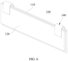
FIG. 6 is a schematic three-dimensional view of an insulating sheet according to a fifth embodiment of this application; -
FIG. 7 is a schematic cross-sectional view of the insulating sheet according to the fifth embodiment of this application; -
FIG. 8 is a schematic three-dimensional view of an insulating sheet according to a sixth embodiment of this application; -
FIG. 9 is a schematic three-dimensional view of an insulating sheet according to a seventh embodiment of this application; -
FIG. 10 is a schematic three-dimensional view of a combination of the insulating sheet and a first tab and a second tab according to the seventh embodiment of this application; -
FIG. 11 is a schematic three-dimensional view of a combination of the insulating sheet and a first tab and a second tab according to the seventh embodiment of this application; -
FIG. 12 is a schematic side view of a combination of the insulating sheet and a first tab and a second tab according to the seventh embodiment of this application; -
FIG. 13 is a schematic three-dimensional view of an insulating sheet according to an eighth embodiment of this application; -
FIG. 14 is a schematic cross-sectional view of a combination of an insulating sheet and a first tab according to a ninth embodiment of this application; and -
FIG. 15 is a schematic cross-sectional view of a battery cell according to the second embodiment of this application. - For ease of understanding this application, the following further describes this application in detail with reference to the accompanying drawings and specific embodiments. It should be noted that when an element is "fixed to" another element, the element may be directly on the another element, or there may be one or more elements between the elements. When an element is "connected to" another element, the element may be directly connected to the another element, or there may be one or more elements between the elements. Terms such as "vertical", "horizontal", "left", "right", and similar expressions used in this specification are for illustration only.
- Unless otherwise defined, all technical and scientific terms used in the specification shall have the same meanings as commonly understood by those skilled in the art to which this application pertains. The terms used in the specification of this application are for description of specific embodiments only without any intention to limit this application. The term "or/and" used in the specification includes any and all combinations of one or more associated items listed.
- A battery cell includes a housing, an electrode assembly, an insulating sheet, and a pole. The housing defines an accommodating cavity, and the electrode assembly is disposed in the accommodating cavity. The poles penetrate the housing to be electrically connected to the electrode assembly, so as to output electrical energy of the battery cell. The electrode assembly includes two electrode plates with opposite polarities, namely a first electrode plate and a second electrode plate. The first electrode plate includes a first current collector and a first tab, and the second electrode plate includes a second current collector and a second tab. The first tab and the second tab separately bypass the insulating sheet and are supported by the wall surfaces of the insulating sheet facing away from the first current collector and the second current collector, so as to be electrically connected to the pole. In existing battery cells, the first tab and the second tab are prone to movement relative to the insulating sheet and contact with the housing, resulting in a short circuit; and the part of the first tab located on a side of the insulating sheet close to a wall surface of the second current collector is prone to contact with the second current collector, resulting in a short circuit.
- In view of this, referring to
FIGs. 1 to 14 , this application provides aninsulating sheet 100 used for abattery cell 10. The insulatingsheet 100 can improve the safety performance of thebattery cell 10. Specifically, thebattery cell 10 includes anelectrode assembly 300, and theelectrode assembly 300 includes afirst tab 310 and asecond tab 320 with opposite polarities. - The insulating
sheet 100 includes afirst sheet body 110 and asecond sheet body 120, and thefirst sheet body 110 includes afirst wall surface 114. Thesecond sheet body 120 is connected to thefirst sheet body 110, and thesecond sheet body 120 includes asecond wall surface 123 facing thefirst wall surface 114. Referring toFIGs. 1 and 2 , thefirst wall surface 114 may be apart from thefirst wall surface 114. Referring toFIG. 5 , thefirst wall surface 114 and thesecond wall surface 123 may be partially in contact with and partially apart from each other. Thefirst wall surface 114 and thesecond wall surface 123 may be planar walls, curved walls, or irregular walls. - Referring to
FIGs. 1 and 2 , thefirst wall surface 114 and thesecond wall surface 123 jointly define afirst gap 150, and thefirst gap 150 has afirst port 151 and asecond port 152 distributed opposite each other. In one embodiment, thefirst wall surface 114 and thesecond wall surface 123 may be apart from each other to define thefirst gap 150. Referring toFIG. 4 , in another embodiment, thefirst wall surface 114 and thesecond wall surface 123 each has a recess, and the two recesses jointly form thefirst gap 150. - A direction from the
first port 151 to thesecond port 152 is a first direction X, the first direction X intersects with a direction perpendicular to the first wall surface 114 (that is, the first direction X is not perpendicular to the first wall surface 114), and the insulatingsheet 100 is configured to allow thefirst tab 310 to sequentially pass through thefirst port 151, thefirst gap 150, and thesecond port 152. - When the insulating
sheet 100 is in use, thefirst sheet body 110 can be made to be located between thesecond sheet body 120 and theelectrode assembly 300. Thefirst tab 310 of theelectrode assembly 300 extends out of thefirst gap 150 from thefirst port 151, then extends out from thesecond port 152, and bends to be attached to or apart from a wall surface of thesecond sheet body 120 facing away from thefirst sheet body 110, thereby facilitating the connection between thefirst tab 310 and apole 400. - For the insulating
sheet 100 of this application, in a first aspect, since thefirst tab 310 is clamped by thefirst sheet body 110 and thesecond sheet body 120, a position of thefirst tab 310 relative to the entire insulatingsheet 100 is relatively stable, and thefirst tab 310 is not prone to movement relative to the insulatingsheet 100 to come into contact with ahousing 200 of thebattery cell 10 which otherwise leads to a short circuit. - In a second aspect, since a current collector of the
electrode assembly 300 can be in contact with only a wall surface of thefirst sheet body 110 facing away from thefirst wall surface 114 and cannot be in contact with a part of thefirst tab 310 located between thefirst sheet body 110 and thesecond sheet body 120, it is difficult for thefirst tab 310 to come into contact with a current collector with opposite polarity which otherwise leads to a short circuit, thereby improving the safety performance of thebattery cell 10. - In a third aspect, since the current collector cannot be in contact with the part of the
first tab 310 located between thefirst sheet body 110 and thesecond sheet body 120, tab adhesive on this part can be omitted, reducing material costs of thebattery cell 10. - It should be noted that in this application, the
first sheet body 110 and thesecond sheet body 120 may be connected before or during the assembly process with thefirst tab 310. The assembly manner of thefirst tab 310 and the insulatingsheet 100 may vary depending on the connection manner of thefirst sheet body 110 and thesecond sheet body 120. For example, when thefirst sheet body 110 and thesecond sheet body 120 are connected to each other before the assembly with thefirst tab 310, thefirst tab 310 is assembled with the insulatingsheet 100 by passing through thefirst gap 150. When thefirst sheet body 110 and thesecond sheet body 120 are connected to each other during the assembly process with thefirst tab 310, thefirst sheet body 110 and thesecond sheet body 120 can first clamp thefirst tab 310, and then thefirst sheet body 110 and thesecond sheet body 120 are connected, thereby completing the assembly of the insulatingsheet 100 and thefirst tab 310. Compared with the assembly manner of making thefirst tab 310 pass through thefirst gap 150, this assembly manner features simpler and more convenient processing. - A specific connection manner of the
first sheet body 110 and thesecond sheet body 120 is determined based on actual needs. For example, the connection manner of thefirst sheet body 110 and thesecond sheet body 120 may satisfy at least one of the following conditions (a) to (d). - (a) The
first sheet body 110 and thesecond sheet body 120 are connected through hot melting. Positions for hot melting of the two are determined based on needs, specifically, outer peripheral edges of the two may be connected through hot melting. The hot melting connection features simple operation without the need for additional components, and features low costs. - (b) Referring to
FIG. 4 , thefirst sheet body 110 and thesecond sheet body 120 are connected through adhesion. Specifically, the insulatingsheet 100 may further include anadhesion member 170, and theadhesion member 170 is configured to adhere thefirst sheet body 110 and thesecond sheet body 120. The adhesion manner and adhesion position of theadhesion member 170 are determined based on specific needs. In an embodiment, theadhesion member 170 may be disposed between thefirst sheet body 110 and thesecond sheet body 120, which can not only hide the part of theadhesion member 170 without occupying too much space of thebattery cell 10, but also keep a certain distance between thefirst sheet body 110 and thesecond sheet body 120, facilitating the definition of thefirst gap 150. - (c) Referring to
FIGs. 6 to 8 , the insulatingsheet 100 includes a first connectingportion 140 clamping thefirst sheet body 110 and thesecond sheet body 120, the first connectingportion 140 including afirst part 141 and asecond part 142 elastically connected to each other. Thefirst part 141 abuts against a wall surface of thefirst sheet body 110 facing away from thefirst wall surface 114, so that an elastic pushing force in a direction from thefirst sheet body 110 to thesecond sheet body 120 is generated against thefirst sheet body 110. Thesecond part 142 abuts against a wall surface of thesecond sheet body 120 facing away from thesecond wall surface 123, so that an elastic pushing force in a direction from thesecond sheet body 120 to thefirst sheet body 110 is generated against thesecond sheet body 120. The first connectingportion 140 connects thefirst sheet body 110 and thesecond sheet body 120 by clamping thefirst sheet body 110 and thesecond sheet body 120. This manner features simple assembly, easy disassembling, and convenient maintenance. - (d) The insulating portion includes a second connecting portion, where one end of the second connecting portion is fixedly connected to the
first sheet body 110, and another end is fixedly connected to thesecond sheet body 120. A material of the second connecting portion may be the same as or different from material of thefirst sheet body 110 and thesecond sheet body 120. When the material of the second connecting portion is the same as the material of thefirst sheet body 110 and thesecond sheet body 120, thefirst sheet body 110, thesecond sheet body 120, and the second connecting portion can be integrally formed for connection. - Referring to
FIG. 2 , in the first direction X, thefirst sheet body 110 includes afirst side edge 111 facing away from thefirst port 151, and thesecond sheet body 120 includes asecond side edge 121 facing away from thefirst port 151, where thesecond side edge 121 is located between thefirst side edge 111 and thefirst port 151, and thesecond side edge 121 and thefirst wall surface 114 jointly define thesecond port 152. In other words, in this embodiment, in the first direction X, width of thefirst sheet body 110 is greater than width of thesecond sheet body 120, so that when thefirst tab 310 is bent to be attached to or apart from the wall surface of thesecond sheet body 120 facing away from thesecond wall surface 123, thefirst tab 310 is not prone to movement along the first direction X beyond thefirst side edge 111 of thefirst sheet body 110 to come into contact with thehousing 200 of thebattery cell 10, improving the safety of thebattery cell 10. - Referring to
FIGs. 8 to 14 , in some embodiments, thefirst wall surface 114 is provided with a protrudingportion 160, where the protrudingportion 160 is disposed on a side of thesecond port 152 facing away from thefirst port 151. The protrudingportion 160 can limit the movement of thefirst tab 310 toward thefirst side edge 111, which can further reduce the probability of thefirst tab 310 moving beyond thefirst side edge 111 of thefirst sheet body 110, and can also prevent a bent part of thefirst tab 310 from coming into contact with a lower housing body (as shown inFIG. 15 ) of thehousing 200 which otherwise leads to a short circuit, thereby improving the safety performance of thebattery cell 10. - Referring to
FIGs. 1 and 2 , in some embodiments, in the first direction X, thefirst sheet body 110 includes athird side edge 112 facing away from thesecond port 152, and thesecond sheet body 120 includes afourth side edge 122 facing away from thesecond port 152. Thethird side edge 112 and thefourth side edge 122 jointly define thefirst port 151. In the above solution, thefirst port 151 is obtained without additional holes provided in thefirst sheet body 110 and thesecond sheet body 120, and thefirst port 151 can be directly obtained through the gap between thethird side edge 112 and thefourth side edge 122, featuring simpler structure and allowing for more convenient assembly process of thefirst tab 310 and the insulatingsheet 100. - Referring to
FIG. 12 , in some embodiments, thefirst sheet body 110 is provided with a first throughhole 113, where the first throughhole 113 penetrates thefirst sheet body 110 along a thickness direction of thefirst sheet body 110, and the first throughhole 113 includes thefirst port 151. In the above solution, thefirst port 151 is defined by providing a hole in thefirst sheet body 110, and thefirst tab 310 can be positioned by the surrounding hole wall of the first throughhole 113, making thefirst tab 310 less prone to displacement relative to thefirst sheet body 110, thereby enhancing a limiting effect on thefirst tab 310. - Referring to
FIGs. 9 to 14 , in some embodiments, in the first direction X, thefirst sheet body 110 includes athird side edge 112 facing away from thesecond port 152, and thesecond sheet body 120 includes afourth side edge 122 facing away from thesecond port 152. The insulating portion includes a third connectingportion 130, where one end of the third connectingportion 130 is connected to thethird side edge 112, and another end is connected to thefourth side edge 122. In the above solution, the third connectingportion 130 does not occupy additional space in the direction perpendicular to thefirst wall surface 114, so the overall thickness of the insulatingsheet 100 is not increased, reducing the space occupied by the insulatingsheet 100 inside thebattery cell 10, and increasing the energy density of thebattery cell 10. - When the third connecting
portion 130 is connected to thefourth side edge 122 and thefourth side edge 122, in an embodiment, thefirst sheet body 110, thesecond sheet body 120, and the third connectingportion 130 may be configured to be integrally formed from a sheet material, and the third connectingportion 130 is bent to make thefirst wall surface 114 face thesecond wall surface 123. In the above solution, the insulatingsheet 100 can be processed from one part, which not only allows for more reliable connection between thefirst sheet body 110 and thesecond sheet body 120, but can also reduce the number of parts of the insulatingsheet 100, simplifying the processing steps of the insulatingsheet 100, and reducing the processing costs of the insulatingsheet 100. - In addition, when the
first sheet body 110, thesecond sheet body 120, and the third connectingportion 130 are configured to be integrally formed from a sheet material, the first protruding portion can be configured to be formed by thefirst sheet body 110 through stamping process. For example, stamping can be performed on the wall surface of thefirst sheet body 110 facing away from thefirst wall surface 114, so as to create a depression on the wall surface of thefirst sheet body 110 facing away from thefirst wall surface 114, and create a protrusion on thefirst wall surface 114 of thefirst sheet body 110, where the protrusion is the foregoing protrudingportion 160. - Referring to
FIG. 11 , in some embodiments, the third connectingportion 130 is provided with several second throughholes 131 arranged along a length direction of thethird side edge 112, each second throughhole 131 communicating with the gap between thefirst wall surface 114 and thesecond wall surface 123. Provision of the second throughholes 131 makes the third connectingportion 130 easier to be bent, reducing the difficulty of the bending process, and also reducing the possibility of cracks in the third connectingportion 130 due to bending. The number, shape, and size of the second throughhole 131 are determined based on specific needs. - In some embodiments, to facilitate the bending of the third connecting
portion 130, the third connectingportion 130 can be made thinner than thefirst sheet body 110 and thesecond sheet body 120. Specifically, the third connectingportion 130 can be provided with a groove parallel to a length direction of thefirst side edge 111. This groove can be formed through stamping process or obtained through milling process. - In some embodiments, the insulating
sheet 100 satisfies one of the following conditions (e) to (g). - (e) Referring to
FIG. 14 , thefirst port 151 is disposed on the third connectingportion 130. In this way, the amount of the material of the third connectingportion 130 can be reduced, facilitating bending of the third connectingportion 130. - (f) The third connecting
portion 130 and thethird side edge 112 jointly define thefirst port 151. To be specific, thefirst port 151 is disposed at the junction between the third connectingportion 130 and thethird side edge 112, which can also facilitate the bending of the third connectingportion 130 relative to thefirst sheet body 110. - (g) Referring to
FIGs. 9 to 12 , the third connectingportion 130, thethird side edge 112, and thefourth side edge 122 jointly define thefirst port 151. In this way, the amount of the material of the third connectingportion 130 can be reduced, facilitating bending of the third connectingportion 130. - One insulating
sheet 100 may be assembled with only thefirst tab 310 but not with thesecond tab 320. For example, in an embodiment, two insulatingsheets 100 may be provided, where one insulatingsheet 100 is assembled with thefirst tab 310, and the other insulatingsheet 100 is assembled with thesecond tab 320. - In some embodiments, the
first wall surface 114 and thesecond wall surface 123 further define a second gap, where the second gap has a third port and a fourth port distributed opposite each other in the first direction X, and the insulatingsheet 100 is configured to allow thesecond tab 320 to sequentially pass through the third port and the fourth port. In this way, the insulatingsheet 100 can be assembled with both thefirst tab 310 and thesecond tab 320, and the insulatingsheet 100 can reduce the probability of thesecond tab 320 coming into contact with a current collector with opposite polarity which otherwise leads to a short circuit, thereby further improving the safety performance of thebattery cell 10. - In some embodiments, the insulating
sheet 100 satisfies at least one of the following conditions (h) to (j): - (h) the
first gap 150 communicates with the second gap; - (i) the
first port 151 communicates with the third port; or - (j) the
second port 152 communicates with the fourth port. - In a specific embodiment, referring to
FIG. 1 , in an embodiment, thefirst wall surface 114 of thefirst sheet body 110 and thesecond wall surface 123 can be apart from each other, so that thefirst gap 150 communicates with the second gap, thefirst port 151 communicates with the third port, and thesecond port 152 communicates with the fourth port. Thefirst tab 310 and thesecond tab 320 can both pass through the gap between thefirst wall surface 114 and thesecond wall surface 123. In this solution, thefirst gap 150, the second gap, thefirst port 151, thesecond port 152, the third port, and the fourth port feature simpler and more convenient processing, and low processing costs. - Referring to
FIG. 15 , a second aspect of this application further provides abattery cell 10, where thebattery cell 10 includes the insulatingsheet 100 according to any one of the foregoing embodiments and theelectrode assembly 300. Thebattery cell 10 further includes ahousing 200 and apole 400. Theelectrode assembly 300 is disposed in thehousing 200, and thepole 400 penetrates thehousing 200. An end of thepole 400 inside thehousing 200 is electrically connected to theelectrode assembly 300, and an end of thepole 400 outside thehousing 200 is used to output the electrical energy of thebattery cell 10. - A third aspect of the this application further provides a battery, where the battery includes one or
more battery cells 10 described above. - A fourth aspect of the this application further provides an electronic apparatus, where the electronic apparatus includes one or
more battery cells 10 described above. - It should be noted that although this specification and the accompanying drawings of this application provide preferable embodiments of this application, this application can be implemented in many different forms, and is not limited to the embodiments described in this specification. These embodiments should not be construed as additional limitations on the content of this application, and these embodiments are provided for ease of a more thorough and comprehensive understanding of the disclosed content of this application. In addition, the foregoing technical features are further mutually combined to form various embodiments not listed above, and these embodiments are all construed as falling within the scope recorded in this specification of this application; and further, persons of ordinary skill in the art can make improvements or changes based on the foregoing descriptions, and all these improvements and changes shall fall within the protection scope of the appended claims of this application.
Claims (15)
- An insulating sheet, used for a battery cell, the battery cell comprising an electrode assembly and the electrode assembly comprising a first tab, wherein the insulating sheet comprises:a first sheet body, comprising a first wall surface; anda second sheet body, configured to be connected to the first sheet body, wherein the second sheet body comprises a second wall surface facing the first wall surface, the first wall surface and the second wall surface jointly define a first gap, and the first gap has a first port and a second port distributed opposite each other;wherein a direction from the first port to the second port is a first direction, the first direction intersects with a direction perpendicular to the first wall surface, and the insulating sheet is configured to allow the first tab to sequentially pass through the first port and the second port.
- The insulating sheet according to claim 1, satisfying at least one of the following conditions (a) to (d):(a) the first sheet body and the second sheet body are connected through hot melting;(b) the first sheet body and the second sheet body are connected through adhesion;(c) the insulating sheet comprises a first connecting portion clamping the first sheet body and the second sheet body, the first connecting portion comprising a first part and a second part elastically connected to each other; wherein the first part abuts against a wall surface of the first sheet body facing away from the first wall surface, so that an elastic pushing force in a direction from the first sheet body to the second sheet body is generated against the first sheet body; and the second part abuts against a wall surface of the second sheet body facing away from the second wall surface, so that an elastic pushing force in a direction from the second sheet body to the first sheet body is generated against the second sheet body; or(d) the insulating portion comprises a second connecting portion, wherein one end of the second connecting portion is fixedly connected to the first sheet body, and another end is fixedly connected to the second sheet body.
- The insulating sheet according to claim 1, wherein
in the first direction, the first sheet body comprises a first side edge facing away from the first port, and the second sheet body comprises a second side edge facing away from the first port, wherein the second side edge is located between the first side edge and the first port, and the second side edge and the first wall surface jointly define the second port. - The insulating sheet according to claim 3, wherein
the first wall surface is provided with a protruding portion, wherein the protruding portion is disposed on a side of the second port facing away from the first port. - The insulating sheet according to claim 1, whereinin the first direction, the first sheet body comprises a third side edge facing away from the second port, and the second sheet body comprises a fourth side edge facing away from the second port; whereinthe third side edge and the fourth side edge jointly define the first port.
- The insulating sheet according to claim 1, wherein
the first sheet body is provided with a first through hole, wherein the first through hole penetrates the first sheet body along a thickness direction of the first sheet body, and the first through hole comprises the first port. - The insulating sheet according to claim 1, whereinin the first direction, the first sheet body comprises a third side edge facing away from the second port, and the second sheet body comprises a fourth side edge facing away from the second port; whereinthe insulating portion comprises a third connecting portion, wherein one end of the third connecting portion is connected to the third side edge, and another end is connected to the fourth side edge.
- The insulating sheet according to claim 7, wherein
the first sheet body, the second sheet body, and the third connecting portion are configured to be integrally formed from a sheet material, and the connecting portion is bent to make the first wall surface face the second wall surface. - The insulating sheet according to claim 8, wherein
the third connecting portion is provided with several second through holes arranged along a length direction of the third side edge, each second through hole communicating with the gap between the first wall surface and the second wall surface. - The insulating sheet according to claim 7, satisfying one of the following conditions (e) to (g):(e) the first port is disposed on the third connecting portion;(f) the third connecting portion and the third side edge j ointly define the first port; and(g) the third connecting portion, the third side edge, and the fourth side edge jointly define the first port.
- The insulating sheet according to claim 1, whereinthe electrode assembly further comprises a second tab, wherein the second tab has a polarity opposite to that of the first tab; andthe first wall surface and the second wall surface further define a second gap, wherein the second gap has a third port and a fourth port distributed opposite each other in the first direction, and the insulating sheet is configured to allow the second tab to sequentially pass through the third port and the fourth port.
- The insulating sheet according to claim 11, satisfying at least one of the following conditions (h) to (j):(h) the first gap communicates with the second gap;(i) the first port communicates with the third port; or(j) the second port communicates with the fourth port.
- A battery cell, comprising:the insulating sheet according to any one of claims 1 to 12; andthe electrode assembly.
- A battery, comprising one or more battery cells according to claim 13.
- An electronic apparatus, comprising one or more battery cells according to claim 13.
Applications Claiming Priority (1)
| Application Number | Priority Date | Filing Date | Title |
|---|---|---|---|
| PCT/CN2022/079460 WO2023168545A1 (en) | 2022-03-07 | 2022-03-07 | Insulating sheet, battery cell, battery and electronic device |
Publications (2)
| Publication Number | Publication Date |
|---|---|
| EP4489208A1 true EP4489208A1 (en) | 2025-01-08 |
| EP4489208A4 EP4489208A4 (en) | 2025-11-05 |
Family
ID=87936915
Family Applications (1)
| Application Number | Title | Priority Date | Filing Date |
|---|---|---|---|
| EP22930194.0A Pending EP4489208A4 (en) | 2022-03-07 | 2022-03-07 | INSULATION FILM, BATTERY CELL, BATTERY AND ELECTRONIC DEVICE |
Country Status (4)
| Country | Link |
|---|---|
| US (1) | US20240429578A1 (en) |
| EP (1) | EP4489208A4 (en) |
| CN (1) | CN116802916A (en) |
| WO (1) | WO2023168545A1 (en) |
Family Cites Families (10)
| Publication number | Priority date | Publication date | Assignee | Title |
|---|---|---|---|---|
| JP6274034B2 (en) * | 2014-06-30 | 2018-02-07 | 株式会社豊田自動織機 | Power storage device |
| CN205609629U (en) * | 2016-04-28 | 2016-09-28 | 宁德时代新能源科技股份有限公司 | Energy memory encapsulates subassembly |
| CN206250229U (en) * | 2016-12-02 | 2017-06-13 | 宁德时代新能源科技股份有限公司 | secondary battery |
| CN206619640U (en) * | 2017-02-21 | 2017-11-07 | 东莞新能源科技有限公司 | Energy storage device |
| CN207938703U (en) * | 2018-02-06 | 2018-10-02 | 比亚迪股份有限公司 | Battery and switching piece |
| JP2020047502A (en) * | 2018-09-20 | 2020-03-26 | 株式会社豊田自動織機 | Manufacturing apparatus of power storage device and manufacturing method of power storage device |
| CN210092210U (en) * | 2019-05-28 | 2020-02-18 | 东莞新能源科技有限公司 | Battery |
| WO2021110179A1 (en) * | 2019-12-06 | 2021-06-10 | 东莞新能德科技有限公司 | Battery, battery assembly, battery pack and electronic apparatus |
| CN214378547U (en) * | 2021-02-01 | 2021-10-08 | 武汉力兴(火炬)电源有限公司 | Button type lithium ion battery |
| CN113270671B (en) * | 2021-05-13 | 2024-04-16 | 宁德新能源科技有限公司 | Battery cells and electrical devices |
-
2022
- 2022-03-07 EP EP22930194.0A patent/EP4489208A4/en active Pending
- 2022-03-07 CN CN202280007309.6A patent/CN116802916A/en active Pending
- 2022-03-07 WO PCT/CN2022/079460 patent/WO2023168545A1/en not_active Ceased
-
2024
- 2024-09-06 US US18/826,785 patent/US20240429578A1/en active Pending
Also Published As
| Publication number | Publication date |
|---|---|
| US20240429578A1 (en) | 2024-12-26 |
| WO2023168545A1 (en) | 2023-09-14 |
| CN116802916A (en) | 2023-09-22 |
| EP4489208A4 (en) | 2025-11-05 |
Similar Documents
| Publication | Publication Date | Title |
|---|---|---|
| US20220238973A1 (en) | Battery and electric apparatus with such battery | |
| CN113346200B (en) | Connecting pieces, individual cells and battery packs | |
| CN216488396U (en) | A battery module | |
| CN111403675A (en) | Batteries and Electronics | |
| US20240243392A1 (en) | Electrochemical apparatus and electronic apparatus | |
| CN217035892U (en) | Battery and electronic device | |
| CN114361385B (en) | Battery and electronic equipment | |
| WO2012063733A1 (en) | Battery module | |
| US20240030521A1 (en) | Battery and electric device | |
| CN219329319U (en) | Cover plate assembly and battery | |
| CN217086828U (en) | Battery and battery pack | |
| CN217086806U (en) | Battery and battery pack | |
| US11682786B2 (en) | Fuel cell unit | |
| US20240429578A1 (en) | Insulating sheet, battery cell, battery, and electronic apparatus | |
| CN217214958U (en) | Battery pack | |
| CN216597902U (en) | Switching piece, battery and group battery | |
| CN220290868U (en) | a single battery | |
| CN218827722U (en) | Battery with a battery cell | |
| CN219575873U (en) | Battery assembly | |
| CN218788475U (en) | Secondary battery and battery pack | |
| CN215933704U (en) | Batteries and battery packs | |
| EP4645573A1 (en) | Electrical connection assembly, battery assembly and vehicle | |
| WO2024026861A1 (en) | Adapter member, battery cell, battery, and electric device | |
| CN214384784U (en) | Cells and electrical devices | |
| CN223514096U (en) | Pole, cover plate assembly and battery |
Legal Events
| Date | Code | Title | Description |
|---|---|---|---|
| STAA | Information on the status of an ep patent application or granted ep patent |
Free format text: STATUS: THE INTERNATIONAL PUBLICATION HAS BEEN MADE |
|
| PUAI | Public reference made under article 153(3) epc to a published international application that has entered the european phase |
Free format text: ORIGINAL CODE: 0009012 |
|
| STAA | Information on the status of an ep patent application or granted ep patent |
Free format text: STATUS: REQUEST FOR EXAMINATION WAS MADE |
|
| 17P | Request for examination filed |
Effective date: 20240930 |
|
| AK | Designated contracting states |
Kind code of ref document: A1 Designated state(s): AL AT BE BG CH CY CZ DE DK EE ES FI FR GB GR HR HU IE IS IT LI LT LU LV MC MK MT NL NO PL PT RO RS SE SI SK SM TR |
|
| DAV | Request for validation of the european patent (deleted) | ||
| DAX | Request for extension of the european patent (deleted) | ||
| A4 | Supplementary search report drawn up and despatched |
Effective date: 20251009 |
|
| RIC1 | Information provided on ipc code assigned before grant |
Ipc: H01M 50/50 20210101AFI20251002BHEP |