EP4489191A1 - Adhesive member and electrochemical device - Google Patents
Adhesive member and electrochemical device Download PDFInfo
- Publication number
- EP4489191A1 EP4489191A1 EP22934270.4A EP22934270A EP4489191A1 EP 4489191 A1 EP4489191 A1 EP 4489191A1 EP 22934270 A EP22934270 A EP 22934270A EP 4489191 A1 EP4489191 A1 EP 4489191A1
- Authority
- EP
- European Patent Office
- Prior art keywords
- boundary line
- edge
- adhesive member
- line
- sealing portion
- Prior art date
- Legal status (The legal status is an assumption and is not a legal conclusion. Google has not performed a legal analysis and makes no representation as to the accuracy of the status listed.)
- Pending
Links
Images






Classifications
-
- H—ELECTRICITY
- H01—ELECTRIC ELEMENTS
- H01M—PROCESSES OR MEANS, e.g. BATTERIES, FOR THE DIRECT CONVERSION OF CHEMICAL ENERGY INTO ELECTRICAL ENERGY
- H01M50/00—Constructional details or processes of manufacture of the non-active parts of electrochemical cells other than fuel cells, e.g. hybrid cells
- H01M50/10—Primary casings; Jackets or wrappings
- H01M50/102—Primary casings; Jackets or wrappings characterised by their shape or physical structure
- H01M50/105—Pouches or flexible bags
-
- H—ELECTRICITY
- H01—ELECTRIC ELEMENTS
- H01G—CAPACITORS; CAPACITORS, RECTIFIERS, DETECTORS, SWITCHING DEVICES, LIGHT-SENSITIVE OR TEMPERATURE-SENSITIVE DEVICES OF THE ELECTROLYTIC TYPE
- H01G11/00—Hybrid capacitors, i.e. capacitors having different positive and negative electrodes; Electric double-layer [EDL] capacitors; Processes for the manufacture thereof or of parts thereof
- H01G11/74—Terminals, e.g. extensions of current collectors
-
- H—ELECTRICITY
- H01—ELECTRIC ELEMENTS
- H01G—CAPACITORS; CAPACITORS, RECTIFIERS, DETECTORS, SWITCHING DEVICES, LIGHT-SENSITIVE OR TEMPERATURE-SENSITIVE DEVICES OF THE ELECTROLYTIC TYPE
- H01G11/00—Hybrid capacitors, i.e. capacitors having different positive and negative electrodes; Electric double-layer [EDL] capacitors; Processes for the manufacture thereof or of parts thereof
- H01G11/78—Cases; Housings; Encapsulations; Mountings
- H01G11/80—Gaskets; Sealings
-
- H—ELECTRICITY
- H01—ELECTRIC ELEMENTS
- H01G—CAPACITORS; CAPACITORS, RECTIFIERS, DETECTORS, SWITCHING DEVICES, LIGHT-SENSITIVE OR TEMPERATURE-SENSITIVE DEVICES OF THE ELECTROLYTIC TYPE
- H01G9/00—Electrolytic capacitors, rectifiers, detectors, switching devices, light-sensitive or temperature-sensitive devices; Processes of their manufacture
- H01G9/004—Details
- H01G9/04—Electrodes or formation of dielectric layers thereon
- H01G9/048—Electrodes or formation of dielectric layers thereon characterised by their structure
-
- H—ELECTRICITY
- H01—ELECTRIC ELEMENTS
- H01G—CAPACITORS; CAPACITORS, RECTIFIERS, DETECTORS, SWITCHING DEVICES, LIGHT-SENSITIVE OR TEMPERATURE-SENSITIVE DEVICES OF THE ELECTROLYTIC TYPE
- H01G9/00—Electrolytic capacitors, rectifiers, detectors, switching devices, light-sensitive or temperature-sensitive devices; Processes of their manufacture
- H01G9/004—Details
- H01G9/08—Housing; Encapsulation
- H01G9/10—Sealing, e.g. of lead-in wires
-
- H—ELECTRICITY
- H01—ELECTRIC ELEMENTS
- H01M—PROCESSES OR MEANS, e.g. BATTERIES, FOR THE DIRECT CONVERSION OF CHEMICAL ENERGY INTO ELECTRICAL ENERGY
- H01M50/00—Constructional details or processes of manufacture of the non-active parts of electrochemical cells other than fuel cells, e.g. hybrid cells
- H01M50/10—Primary casings; Jackets or wrappings
- H01M50/172—Arrangements of electric connectors penetrating the casing
- H01M50/174—Arrangements of electric connectors penetrating the casing adapted for the shape of the cells
- H01M50/178—Arrangements of electric connectors penetrating the casing adapted for the shape of the cells for pouch or flexible bag cells
-
- H—ELECTRICITY
- H01—ELECTRIC ELEMENTS
- H01M—PROCESSES OR MEANS, e.g. BATTERIES, FOR THE DIRECT CONVERSION OF CHEMICAL ENERGY INTO ELECTRICAL ENERGY
- H01M50/00—Constructional details or processes of manufacture of the non-active parts of electrochemical cells other than fuel cells, e.g. hybrid cells
- H01M50/10—Primary casings; Jackets or wrappings
- H01M50/183—Sealing members
- H01M50/184—Sealing members characterised by their shape or structure
-
- H—ELECTRICITY
- H01—ELECTRIC ELEMENTS
- H01M—PROCESSES OR MEANS, e.g. BATTERIES, FOR THE DIRECT CONVERSION OF CHEMICAL ENERGY INTO ELECTRICAL ENERGY
- H01M50/00—Constructional details or processes of manufacture of the non-active parts of electrochemical cells other than fuel cells, e.g. hybrid cells
- H01M50/10—Primary casings; Jackets or wrappings
- H01M50/183—Sealing members
- H01M50/186—Sealing members characterised by the disposition of the sealing members
-
- H—ELECTRICITY
- H01—ELECTRIC ELEMENTS
- H01M—PROCESSES OR MEANS, e.g. BATTERIES, FOR THE DIRECT CONVERSION OF CHEMICAL ENERGY INTO ELECTRICAL ENERGY
- H01M50/00—Constructional details or processes of manufacture of the non-active parts of electrochemical cells other than fuel cells, e.g. hybrid cells
- H01M50/50—Current conducting connections for cells or batteries
- H01M50/543—Terminals
- H01M50/547—Terminals characterised by the disposition of the terminals on the cells
- H01M50/55—Terminals characterised by the disposition of the terminals on the cells on the same side of the cell
-
- H—ELECTRICITY
- H01—ELECTRIC ELEMENTS
- H01M—PROCESSES OR MEANS, e.g. BATTERIES, FOR THE DIRECT CONVERSION OF CHEMICAL ENERGY INTO ELECTRICAL ENERGY
- H01M50/00—Constructional details or processes of manufacture of the non-active parts of electrochemical cells other than fuel cells, e.g. hybrid cells
- H01M50/50—Current conducting connections for cells or batteries
- H01M50/543—Terminals
- H01M50/552—Terminals characterised by their shape
- H01M50/553—Terminals adapted for prismatic, pouch or rectangular cells
- H01M50/557—Plate-shaped terminals
-
- H—ELECTRICITY
- H01—ELECTRIC ELEMENTS
- H01G—CAPACITORS; CAPACITORS, RECTIFIERS, DETECTORS, SWITCHING DEVICES, LIGHT-SENSITIVE OR TEMPERATURE-SENSITIVE DEVICES OF THE ELECTROLYTIC TYPE
- H01G11/00—Hybrid capacitors, i.e. capacitors having different positive and negative electrodes; Electric double-layer [EDL] capacitors; Processes for the manufacture thereof or of parts thereof
- H01G11/74—Terminals, e.g. extensions of current collectors
- H01G11/76—Terminals, e.g. extensions of current collectors specially adapted for integration in multiple or stacked hybrid or EDL capacitors
-
- H—ELECTRICITY
- H01—ELECTRIC ELEMENTS
- H01G—CAPACITORS; CAPACITORS, RECTIFIERS, DETECTORS, SWITCHING DEVICES, LIGHT-SENSITIVE OR TEMPERATURE-SENSITIVE DEVICES OF THE ELECTROLYTIC TYPE
- H01G11/00—Hybrid capacitors, i.e. capacitors having different positive and negative electrodes; Electric double-layer [EDL] capacitors; Processes for the manufacture thereof or of parts thereof
- H01G11/78—Cases; Housings; Encapsulations; Mountings
-
- H—ELECTRICITY
- H01—ELECTRIC ELEMENTS
- H01M—PROCESSES OR MEANS, e.g. BATTERIES, FOR THE DIRECT CONVERSION OF CHEMICAL ENERGY INTO ELECTRICAL ENERGY
- H01M2220/00—Batteries for particular applications
- H01M2220/30—Batteries in portable systems, e.g. mobile phone, laptop
-
- Y—GENERAL TAGGING OF NEW TECHNOLOGICAL DEVELOPMENTS; GENERAL TAGGING OF CROSS-SECTIONAL TECHNOLOGIES SPANNING OVER SEVERAL SECTIONS OF THE IPC; TECHNICAL SUBJECTS COVERED BY FORMER USPC CROSS-REFERENCE ART COLLECTIONS [XRACs] AND DIGESTS
- Y02—TECHNOLOGIES OR APPLICATIONS FOR MITIGATION OR ADAPTATION AGAINST CLIMATE CHANGE
- Y02E—REDUCTION OF GREENHOUSE GAS [GHG] EMISSIONS, RELATED TO ENERGY GENERATION, TRANSMISSION OR DISTRIBUTION
- Y02E60/00—Enabling technologies; Technologies with a potential or indirect contribution to GHG emissions mitigation
- Y02E60/10—Energy storage using batteries
Definitions
- This application relates to the field of cell technologies, and in particular, to an adhesive member and an electrochemical device.
- an insulating adhesive tape is typically adhered to the exterior of a pouch cell to provide insulation and protection.
- the adhesive tape is mostly designed with a straight-edge upright opening. This adhesive tape is easily pressed down during transportation and actual production, causing sharp corners. The presence of sharp corners affects the measurement of the outer contour size of the cell, leading to increased labor cost and unsmooth equipment operation, thus increasing the production cost.
- An embodiment of this application provides an adhesive member, including a first edge, a second edge, a third edge, a first boundary line, and a second boundary line.
- the first edge is opposite the second edge
- the third edge includes a first end and a second end opposite the first end, and the first end is connected to the second edge.
- Two ends of the second boundary line are respectively connected to the first boundary line and the first edge, and two ends of the first boundary line are respectively connected to the second boundary line and the second end.
- An included angle R1 is formed by a connection line between the two ends of the first boundary line and a connection line between two ends of the second boundary line, and 5° ⁇ R1 ⁇ 235°.
- 60° ⁇ R1 ⁇ 150° In some embodiments of this application, 60° ⁇ R1 ⁇ 150°.
- 90° ⁇ R1 ⁇ 150° In some embodiments of this application, 90° ⁇ R1 ⁇ 150°.
- the second edge includes a third boundary line, a fourth boundary line, and a fifth boundary line being connected sequentially, two ends of the third boundary line are respectively connected to the fourth boundary line and the first end, an included angle R2 is formed by a connection line between the two ends of the third boundary line and a connection line between two ends of the third edge, and 0° ⁇ R2 ⁇ 180°.
- an included angle R3 is formed by the connection line between the two ends of the third boundary line and a connection line between two ends of the fourth boundary line, and 30° ⁇ R3 ⁇ 180°.
- an included angle R4 is formed by the connection line between the two ends of the fourth boundary line and a connection line between two ends of the fifth boundary line, and 0° ⁇ R4 ⁇ 180°.
- an included angle R5 is formed by the connection line between the two ends of the first boundary line and a first direction, and 5° ⁇ R5 ⁇ 60°, the first direction being a length direction of the adhesive member.
- an included angle R6 is formed by the connection line between the two ends of the second boundary line and a first direction, and 15° ⁇ R6 ⁇ 180°, the first direction being a length direction of the adhesive member.
- An embodiment of this application provides an electrochemical device, including a housing, an electrode assembly, a tab, and the adhesive member according to any one of the foregoing embodiments.
- the housing includes a main body portion, a first sealing portion, and a second sealing portion.
- the first sealing portion and the second sealing portion are both connected to the main body portion.
- the main body portion has a first surface, a second surface, and a third surface being connected to each other.
- the first sealing portion extends beyond the first surface, and the second sealing portion extends beyond the second surface and bends towards the third surface.
- the electrode assembly is accommodated in the main body portion.
- the tab has one end connected to the electrode assembly and another end extending beyond the housing from the first sealing portion.
- the first edge is attached to a side of the second sealing portion back away from the second surface, the second edge is attached to the third surface, and the third edge is attached to the first surface and/or the first sealing portion.
- a crease corresponding to a side edge of the housing is located within the range of the first boundary line and the second boundary line, thereby reducing the risk of sharp corners generated when the adhesive member is pressed down on a surface of the housing, reducing the influence on the outer contour size of the electrochemical device, and further reducing the production cost.
- the second surface intersects the third surface at the first connection line;
- the adhesive member has a crease, the crease being opposite the first connection line; and the crease intersects the first boundary line or an intersection point between the first boundary line and the second boundary line.
- a crease corresponding to a side edge of the cell is located within the range of the first boundary line and the second boundary line, thereby reducing the risk of sharp corners generated when the adhesive member is pressed down on a surface of the cell, reducing the influence on the outer contour size of the cell, and further reducing the production cost.
- Electrochemical device 100 Adhesive member 10 First edge 11 Second edge 12 Third boundary line 121 Fourth boundary line 122 Fifth boundary line 123 Third edge 13 First end 131 Second end 132 First boundary line 14 Second boundary line 15 Crease 16 Fourth edge 17 Housing 20 Main body portion 21 First surface 211 Second surface 212 Third surface 213 First connection line 214 First sealing portion 22 Second sealing portion 23 First layer 24 Third layer 25 First folding portion 26 Second folding portion 27 Accommodation groove 28 Sealing portion 29 Electrode assembly 30 Positive electrode tab 41 Negative electrode tab 42 First direction X Second direction Y
- one component when one component is assumed as being “connected to” another component, it may be connected to the another component directly or with a component possibly present therebetween. When one component is assumed as being “disposed on/in” another component, the component may be provided directly on/in the another component or with a component possibly present therebetween.
- parallel is used to describe the ideal state between two components (edges or lines or surfaces). During actual production or use, an approximately parallel state may be present between the two components.
- "parallel” may indicate that an included angle between two straight lines is within a range of 180° ⁇ 10°
- parallel may alternatively indicate that a dihedral angle of two planes is within a range of 180° ⁇ 10°
- "parallel” may further alternatively indicate that an included angle between a straight line and a plane is within a range of 180° ⁇ 10°.
- Two components described as “parallel” to each other may not be absolutely straight lines or planes, and may be approximately straight lines or planes. From a macro perspective, a component can be considered as a "straight line” or "plane” as long as the overall extension direction is a straight line or a plane.
- perpendicular is used to describe the ideal state between two components (edges or lines or surfaces). In actual production or use, an approximation of this perpendicular state can exist between two parts. For example, with reference to the description of numerical values, “perpendicular” may indicate that an included angle between two straight lines is within a range of 90° ⁇ 10°, “perpendicular” may alternatively indicate that a dihedral angle of two planes is within a range of 90° ⁇ 10°, and “perpendicular” may alternatively indicate that an included angle between a straight line and a plane is within a range of 90° ⁇ 10°.
- Two components described as "perpendicular” to each other may not be absolutely straight lines or planes, and may be approximately straight lines or planes. From a macro perspective, a component can be considered as a "straight line” or “plane” as long as the overall extension direction is a straight line or a plane.
- An embodiment of this application provides an adhesive member, including a first edge, a second edge, a third edge, a first boundary line, and a second boundary line.
- the first edge is opposite the second edge
- the third edge includes a first end and a second end opposite the first end, and the first end is connected to the second edge.
- Two ends of the second boundary line are respectively connected to the first boundary line and the first edge, and two ends of the first boundary line are respectively connected to the second boundary line and the second end.
- An included angle R1 is formed by a connection line between the two ends of the first boundary line and a connection line between two ends of the second boundary line, and 5° ⁇ R1 ⁇ 235°.
- Embodiment 1 of this application provides an adhesive member 10 which can be used to bond a pouch cell, providing insulation and protection.
- the adhesive member 10 includes a first edge 11, a second edge 12, a third edge 13, a first boundary line 14, and a second boundary line 15.
- the first edge 11 is opposite the second edge 12, the third edge 13 is connected to the second edge 12, the third edge 13 is away from the first edge 11, two ends of the first boundary line 14 are respectively connected to the third edge 13 and the second boundary line 15, and two ends of the second boundary line 15 are respectively connected to the first boundary line 14 and the first edge 11.
- the third edge 13 includes a first end 131 and a second end 132 opposite the first end 131.
- the first end 131 is connected to the second edge 12, and the second end 132 is connected to the first boundary line 14.
- An included angle R1 is formed by a connection line between the two ends of the first boundary line 14 and a connection line between two ends of the second boundary line 15, and 5° ⁇ R1 ⁇ 235°.
- the included angle R1 formed by the first boundary line 14 and the second boundary line 15 when the adhesive member 10 is bonded to a cell, the adhesive member 10 and a crease corresponding to a side edge of the cell is located within the range of the first boundary line 14 and the second boundary line 15, thereby reducing the risk of sharp corners generated when the adhesive member 10 is pressed down, reducing the influence on the outer contour size of the cell, and further reducing the production cost.
- the included angle R1 is an included angle that is formed as the connection line between the two ends of the first boundary line 14 intersects the connection line between the two ends of the second boundary line 15 and located outside the adhesive member 10.
- the value of the included angle R1 may be any one of 5°, 15°, 30°, 45°, 60°, 75°, 90°, 95°, 135°, 140°, 145°, 150°, 155°, 160°, 165°, 170°, 175°, 185°, 190°, 195°, 200°, 205°, 210°, 215°, 220°, 225°, 230°, and 235°.
- the adhesive member 10 is made of an insulating material.
- the adhesive member 10 includes an insulating adhesive tape.
- the adhesive member 10 When the adhesive member 10 is bonded to the cell, the adhesive member 10 and the crease corresponding to the side edge of the cell are located within the range of the first boundary line 14 and the second boundary line 15.
- the adhesive member 10 can attach to an exposed metal layer of the housing of the cell to provide insulation and protection. This can further reduce the risks of short circuit in the cell and sharp corners when the side edge of the cell is pressed down, further reducing the impact on the outer contour size of the cell, thus further reducing the production cost.
- first edge 11 and the second edge 12 are parallel to each other and both are parallel to a first direction X, the first direction X being the length direction of the adhesive member 10.
- first direction X being the length direction of the adhesive member 10.
- the length direction of the adhesive member 10 is the extension direction of the adhesive member 10.
- an included angle R5 is formed by the connection line between the two ends of the first boundary line 14 and the first direction X, and 5° ⁇ R5 ⁇ 60°. In an embodiment, 15° ⁇ R5 ⁇ 45°.
- the value of the included angle R5 may be any one of 15°, 20°, 25°, 30°, 35°, 40°, and 45°. In this application, the included angle R5 is the smallest angle formed by the connection line between the two ends of the first boundary line 14 and the first direction X.
- an included angle R6 is formed by the connection line between the two ends of the second boundary line 15 and the first direction X, and 15° ⁇ R6 ⁇ 180°.
- the included angle R6 is an included angle that is formed as the connection line between the two ends of the second boundary line 15 intersects the first direction X and located in the adhesive member 10.
- the value of the included angle R6 may be any one of 15°, 20°, 25°, 30°, 35°, 40°, 45°, 50°, 55°, 60°, 70°, 80°, 90°, 100°, 120°, 135°, 150°, 165°, and 180°.
- R6 90°
- the second boundary line 15 is perpendicular to the first direction X and the first edge 11.
- the adhesive member 10 further includes a fourth edge 17, with two ends of the fourth edge 17 respectively connected to the second boundary line 15 and the first edge 11.
- the length of the first boundary line 14 is d1, and d1>1 mm. In some embodiments, 1.5 mm ⁇ d1 ⁇ 3 mm. In this application, the length d1 is the perpendicular distance between the two ends of the first boundary line 14 along the first direction X. Optionally, the value of d1 may be any one of 1.5 mm, 2 mm, 2.5 mm, and 3 mm.
- the length of the second boundary line 15 is d2, and d2 ⁇ 1 mm. In some embodiments, 1 mm ⁇ d2 ⁇ 5.5 mm. In this application, the length d2 is the perpendicular distance between the two ends of the second boundary line 15 along the second direction Y.
- the value of d2 may be any one of 1mm, 1.5 mm, 2 mm, 2.5 mm, 3 mm, 3.5 mm, 4 mm, 4.5 mm, 5 mm, and 5.5 mm.
- the second direction Y is the width direction of the adhesive member 10.
- the connection line between the first end 131 and the second end 132 of the third edge 13 is parallel to the second direction Y, and the connection line between the first end 131 and the second end 132 is perpendicular to the first edge 11 and the second edge 12.
- the first boundary line 14 intersects the second boundary line 15 to form a structure concave to the adhesive member 10, as shown in FIG. 1 , and R1 ⁇ 180°.
- the first boundary line 14 intersects the second boundary line 15 to form a structure convex from the adhesive member 10, and R1>180°.
- the intersection point of the first boundary line 14 and the second boundary line 15 is located between the intersection point of the first boundary line 14 and the third edge 13, and the intersection point of the second boundary line 15 and the first edge 11.
- the intersection point of the first boundary line 14 and the second boundary line 15 extends beyond the third edge 13 (not shown in the figure).
- the second edge 12 includes a third boundary line 121, a fourth boundary line 122, and a fifth boundary line 123 being connected sequentially. Two ends of the third boundary line 121 are respectively connected to the fourth boundary line 122 and the first end 131, and two ends of the fourth boundary line 122 are respectively connected to the third boundary line 121 and the fifth boundary line 123.
- the fifth boundary line 123 is parallel to the first edge 11.
- An included angle R2 is formed by the connection line between the two ends of the third boundary line 121 and a connection line between the two ends of the third edge 13, and 0° ⁇ R2 ⁇ 180°. In an embodiment, 30° ⁇ R2 ⁇ 150°. In an embodiment, 45° ⁇ R2 ⁇ 120°. In an embodiment, 60° ⁇ R2 ⁇ 120°.
- the value of the included angle R2 may be any one of 60°, 65°, 70°, 75°, 80°, 85°, 90°, 95°, 100°, 105°, 110°, 115°, and 120°.
- an included angle R3 is formed between the connection line between the two ends of the third boundary line 121 and a connection line between two ends of the fourth boundary line 122, and 30° ⁇ R3 ⁇ 180°.
- the included angle R3 is an included angle formed as the connection line between the two ends of the third boundary line 121 intersects the connection line between the two ends of the fourth boundary line 122, and located outside the adhesive member 10.
- the value of the included angle R3 may be any one of 120°, 125°, 130°, 135°, 140°, 145°, 150°, 155°, 160°, 165°, 170°, 175°, and 180°.
- an included angle R4 is formed by the connection line between the two ends of the fourth boundary line 122 and a connection line between two ends of the fifth boundary line 123, and 0° ⁇ R4 ⁇ 180°.
- the included angle R4 is an included angle formed as the connection line between the two ends of the fourth boundary line 122 intersects the connection line between the two ends of the fifth boundary line 123, and located in the adhesive member 10.
- the value of the included angle R4 may be any one of 90°, 95°, 100°, 105°, 110°, 115°, 120°, 125°, 130°, 135°, 140°, 145°, and 150°.
- an included angle R7 is formed by the connection line between the two ends of the third boundary line 121 and the first direction X, and 0° ⁇ R7 ⁇ 90°. In an embodiment, 15° ⁇ R7 ⁇ 60°. In this application, the included angle R7 is the smallest angle formed by the connection line between the two ends of the third boundary line 121 and the first direction X. Optionally, the value of the included angle R7 may be any one of 15°, 17°, 20°, 25°, 30°, 35°, 40°, 45°, 50°, 55°, and 60°.
- an included angle R8 is formed by the connection line between the two ends of the fourth boundary line 122 and the first direction X, and 0° ⁇ R8 ⁇ 90°. In an embodiment, 13° ⁇ R8 ⁇ 60°. In this application, the included angle R8 is the smallest angle formed by the connection line between the two ends of the fourth boundary line 122 and the first direction X. Optionally, the value of the included angle R8 may be any one of 13°, 15°, 20°, 25°, 30°, 35°, 40°, 45°, 50°, 55°, and 60°.
- the length of the third boundary line 121 is d3, and d3 ⁇ 1.5 mm. In some embodiments, 1.5 mm ⁇ d3 ⁇ 3 mm. In this application, the length d3 is the perpendicular distance between the two ends of the third boundary line 121 along the first direction X.
- the value of d3 may be any one of 1.5 mm, 2 mm, 2.5 mm, and 3 mm.
- d3 d1+0.5 mm.
- the length of the fourth boundary line 122 is d4, and d4 ⁇ 1 mm.
- the length d4 is the perpendicular distance between the two ends of the fourth boundary line 122 along the second direction Y
- the value of d3 may be any one of 1.5 mm, 2 mm, 2.5 mm, and 3 mm.
- R1 128°
- R5 20°
- R6 72°
- R2 73°
- R3 150°
- R7 17°
- R8 13°
- R4 167°.
- the first boundary line 14 intersects the second boundary line 15 to form a structure concave to the adhesive member 10.
- the third boundary line 121 intersects the fourth boundary line 122 to form a structure concave to the adhesive member 10.
- R1 165°
- R5 30°
- R6 45°
- R2 73°
- R3 150°
- R7 17°
- R8 13°
- R4 167°.
- the first boundary line 14 intersects the second boundary line 15 to form a structure concave to the adhesive member 10.
- the third boundary line 121 intersects the fourth boundary line 122 to form a structure concave to the adhesive member 10.
- R1 128°
- R5 20°
- R6 72°
- R2 73°
- R3 73°
- R7 17°
- R8 90°
- R4 90°.
- the first boundary line 14 intersects the second boundary line 15 to form a structure concave to the adhesive member 10.
- the third boundary line 121 intersects the fourth boundary line 122 to form a structure concave to the adhesive member 10, and the fourth boundary line 122 is perpendicular to the fifth boundary line 123.
- R1 128°
- R5 20°
- R6 72°
- R2 73°
- R3 163°
- R7 17°
- R8 00°
- R4 180°.
- the first boundary line 14 intersects the second boundary line 15 to form a structure concave to the adhesive member 10.
- the third boundary line 121 intersects the fourth boundary line 122 to form a structure concave to the adhesive member 10.
- both the fourth boundary line 122 and the fifth boundary line 123 are parallel to the first edge 11.
- Embodiment 2 of this application provides an electrochemical device 100 that can be used to store electrical energy and supply power to electrical equipment.
- the electrochemical device 100 includes a housing 20, an electrode assembly 30, a tab, and the adhesive member 10 according to Embodiment 1.
- the electrode assembly 30 is accommodated in the housing 20, and the tab has one end connected to the electrode assembly 30 and another end extending beyond of the housing 20.
- the adhesive member 10 is bonded to a surface of the housing 20.
- the housing 20 includes a main body portion 21, a first sealing portion 22, and a second sealing portion 23.
- the electrode assembly 30 is accommodated in the main body portion 21.
- the first sealing portion 22 and the second sealing portion 23 extend beyond the surface of the main body portion 21, and the tab extends beyond the housing 20 from the first sealing portion 22.
- the electrode assembly 30 includes a positive electrode plate, a negative electrode plate, and a separator.
- the separator is placed between the positive electrode plate and the negative electrode plate.
- the positive electrode plate, the separator, and the negative electrode plate are stacked or wound.
- the tab includes a positive electrode tab 41 and a negative electrode tab 42.
- the positive electrode tab 41 has one end connected to the positive electrode plate and another end extending beyond the housing 20.
- the negative electrode tab 42 has one end connected to the negative electrode plate and another end extending beyond the housing 20.
- the main body portion 21 has a first surface 211, a second surface 212, and a third surface 213 being connected to each other.
- the first sealing portion 22 extends beyond the first surface 211
- the second sealing portion 23 extends beyond the second surface 212 and bends towards the third surface 213.
- the second sealing portion 23 is attached to the second surface 212.
- the first edge 11 of the adhesive member 10 is attached to a side of the second sealing portion 23 back away from the second surface 212, the second edge 12 is attached to the third surface 213, and the third edge 13 bends towards the first sealing portion 22 from the third surface 213 to be attached to the first surface 211 and/or the first sealing portion 22.
- the housing 20 before the electrochemical device 100 is packaged, includes a first folding portion 26 and a second folding portion 27, at least one of which is provided with an accommodation groove 28 for accommodating the electrode assembly 30.
- the electrode assembly 30 is accommodated in the accommodation groove 28, and the first folding portion 26 and the second folding portion 27 are folded and connected to form the main body portion 21 and a sealing portion 29.
- the sealing portion 29 extends outwards from the surface of the main body portion 21 and includes the first sealing portion 22 and the second sealing portion 23.
- the housing 20 is a composite layered structure, including a first layer 24, a second layer (not shown in the figure), and a third layer 25.
- the second layer is located between the first layer 24 and the third layer 25.
- the first layer 24 forms the inner surface of the housing 20, and the third layer 25 forms the outer surface of the housing 20.
- the first layer 24 and the second layer are connected by a binder, and the second layer and the third layer 25 are connected by a binder.
- the material of the first layer 24 includes but is not limited to polypropylene. In an embodiment, the first layer 24 features corrosion resistance to electrolyte.
- the material of the second layer is metal, including but not limited to aluminum and steel.
- the material of the third layer 25 includes but is not limited to nylon.
- the third layer 25 protects the second layer, reducing the risk of the second layer being scratched or punctured.
- the end surface of the second sealing portion 23 away from the main body portion 21 exposes the second layer, which increases the risk of short circuit in the electrochemical device 100.
- the first edge 11 of the adhesive member 10 is attached to the second sealing portion 23, and the second edge 12 is attached to the third surface 213, covering the exposed second layer at the end of the second sealing portion 23, thereby reducing the risk of short circuit in the electrochemical device 100.
- the housing 20, the electrode assembly 30, and the tab form a pouch cell.
- the second surface 212 intersects the third surface 213 at the first connection line 214, and the adhesive member 10 has a crease 16, with the crease 16 being opposite the first connection line 214.
- the crease 16 intersects an intersection point of the first boundary line 14 and the second boundary line 15. In an embodiment, the crease 16 intersects the first boundary line 14. In an embodiment, the crease 16 intersects the second boundary line 15. The crease 16 intersects the first boundary line 14 and/or the second boundary line 15, such that when the first edge 11 is attached to a side of the second sealing portion 23 back away from the second surface 212, the adhesive member 10 can cover the exposed second layer of the second sealing portions 23, thereby reducing the risk of short circuit in the electrochemical device 100.
- the crease 16 is parallel to the first edge 11.
- At least part of the adhesive member 10 extends beyond the first surface 211, the part of the adhesive member 10 extending beyond the first surface 211 bends towards the first sealing portion 22, and the third edge 13 is attached to the first surface 211 and/or the first sealing portion 22.
- the crease 16 intersects an intersection point of the first boundary line 14 and the second boundary line 15.
- the first boundary line 14 intersects the second boundary line 15 to form a structure convex from the adhesive member 10, and the crease 16 intersects the second boundary line 15, as shown in FIG. 2 .
- the thickness of the electrochemical device 100 is D1, and d2 ⁇ 110%*D1, such that the part of the adhesive member 10 between the crease 16 and the first edge 11 can be stably bonded to the second surface 212 and the second sealing portion 23, reducing the risk of the adhesive member 10 peeling off.
- the length of the first sealing portion 22 extending beyond the first surface 211 is D2, d1 ⁇ D2, and d3 ⁇ D2, such that the part of the adhesive member 10 extending beyond the first surface 211 can be stably bonded to the first surface 211 and/or the first sealing portion 22, reducing the risk of the adhesive member 10 peeling off.
- the width of the electrochemical device 100 is D3, and d4 ⁇ D3, such that the part of the adhesive member 10 between the crease 16 and the second edge 12 can be stably adhered to the third surface 213, reducing the risk of the adhesive member 10 peeling off.
- the main body portion 21 further includes a fourth surface (not shown in the figure), which is opposite the second surface 212 and connects the first surface 211 and the third surface 213.
- the housing 20 further includes a third sealing portion (not shown in the figure), which extends beyond the fourth surface and bends towards the third surface 213.
- the electrochemical device 100 includes two adhesive members 10. The first edge 11 of one adhesive member 10 is attached to the second sealing portion 23, the first edge 11 of the other adhesive member 10 is attached to the fourth sealing portion, and the second edge 12 of the other adhesive member 10 is attached to the third surface 213.
- the adhesive members 10 are attached to the housing 20 in the same manner, which is not elaborated herein.
- the second sealing portion 23 extends beyond the first surface 211 and bends towards the third surface 213, with the part extending beyond the first surface 211 bending towards the first surface 211.
- the third edge 13 is partially attached to the first surface 211, to the second sealing portion 23 located on the first surface 211, and to the first sealing portion 22. In an embodiment, the third edge 13 is partially attached to the second sealing portion 23 located on the first surface 211 and to the first sealing portion 22.
Landscapes
- Chemical & Material Sciences (AREA)
- Chemical Kinetics & Catalysis (AREA)
- Electrochemistry (AREA)
- General Chemical & Material Sciences (AREA)
- Engineering & Computer Science (AREA)
- Power Engineering (AREA)
- Microelectronics & Electronic Packaging (AREA)
- Sealing Battery Cases Or Jackets (AREA)
- Fuel Cell (AREA)
Abstract
Description
- This application relates to the field of cell technologies, and in particular, to an adhesive member and an electrochemical device.
- Currently, an insulating adhesive tape is typically adhered to the exterior of a pouch cell to provide insulation and protection. At a side edge of the cell, the adhesive tape is mostly designed with a straight-edge upright opening. This adhesive tape is easily pressed down during transportation and actual production, causing sharp corners. The presence of sharp corners affects the measurement of the outer contour size of the cell, leading to increased labor cost and unsmooth equipment operation, thus increasing the production cost.
- In view of the foregoing situation, it is necessary to provide an adhesive member, so as to reduce the risk of sharp corners generated when the adhesive member is pressed down on a surface of a cell, reduce the influence on the outer contour size of the cell, and further reduce the production cost.
- An embodiment of this application provides an adhesive member, including a first edge, a second edge, a third edge, a first boundary line, and a second boundary line. The first edge is opposite the second edge, the third edge includes a first end and a second end opposite the first end, and the first end is connected to the second edge. Two ends of the second boundary line are respectively connected to the first boundary line and the first edge, and two ends of the first boundary line are respectively connected to the second boundary line and the second end. An included angle R1 is formed by a connection line between the two ends of the first boundary line and a connection line between two ends of the second boundary line, and 5°≤R1≤235°.
- With the included angle R1 formed by the first boundary line and the second boundary line, when the adhesive member is bonded to a cell, a crease corresponding to a side edge of the cell is located within the range of the first boundary line and the second boundary line, thereby reducing the risk of sharp corners generated when the adhesive member is pressed down on a surface of the cell, reducing the influence on the outer contour size of the cell.
- In some embodiments of this application, 30°≤R1<180°.
- In some embodiments of this application, 60°≤R1≤150°.
- In some embodiments of this application, 90°≤R1≤150°.
- In some embodiments of this application, the second edge includes a third boundary line, a fourth boundary line, and a fifth boundary line being connected sequentially, two ends of the third boundary line are respectively connected to the fourth boundary line and the first end, an included angle R2 is formed by a connection line between the two ends of the third boundary line and a connection line between two ends of the third edge, and 0°<R2<180°.
- In some embodiments of this application, 30°≤R2≤150°.
- In some embodiments of this application, an included angle R3 is formed by the connection line between the two ends of the third boundary line and a connection line between two ends of the fourth boundary line, and 30°≤R3≤180°.
- In some embodiments of this application, 60°≤R3≤180°.
- In some embodiments of this application, an included angle R4 is formed by the connection line between the two ends of the fourth boundary line and a connection line between two ends of the fifth boundary line, and 0°<R4≤180°.
- In some embodiments of this application, 30°≤R4≤180°.
- In some embodiments of this application, an included angle R5 is formed by the connection line between the two ends of the first boundary line and a first direction, and 5°≤R5≤60°, the first direction being a length direction of the adhesive member.
- In some embodiments of this application, an included angle R6 is formed by the connection line between the two ends of the second boundary line and a first direction, and 15°≤R6≤180°, the first direction being a length direction of the adhesive member.
- An embodiment of this application provides an electrochemical device, including a housing, an electrode assembly, a tab, and the adhesive member according to any one of the foregoing embodiments. The housing includes a main body portion, a first sealing portion, and a second sealing portion. The first sealing portion and the second sealing portion are both connected to the main body portion. The main body portion has a first surface, a second surface, and a third surface being connected to each other. The first sealing portion extends beyond the first surface, and the second sealing portion extends beyond the second surface and bends towards the third surface. The electrode assembly is accommodated in the main body portion. The tab has one end connected to the electrode assembly and another end extending beyond the housing from the first sealing portion. The first edge is attached to a side of the second sealing portion back away from the second surface, the second edge is attached to the third surface, and the third edge is attached to the first surface and/or the first sealing portion.
- With the included angle R1 formed by the first boundary line and the second boundary line, when the adhesive member is bonded to the housing, a crease corresponding to a side edge of the housing is located within the range of the first boundary line and the second boundary line, thereby reducing the risk of sharp corners generated when the adhesive member is pressed down on a surface of the housing, reducing the influence on the outer contour size of the electrochemical device, and further reducing the production cost.
- In some embodiments of this application, the second surface intersects the third surface at the first connection line; the adhesive member has a crease, the crease being opposite the first connection line; and the crease intersects the first boundary line or an intersection point between the first boundary line and the second boundary line.
- In summary, with the included angle R1 formed by the first boundary line and the second boundary line, when the adhesive member in some embodiments of this application is bonded to a cell, a crease corresponding to a side edge of the cell is located within the range of the first boundary line and the second boundary line, thereby reducing the risk of sharp corners generated when the adhesive member is pressed down on a surface of the cell, reducing the influence on the outer contour size of the cell, and further reducing the production cost.
-
-
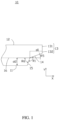
FIG. 1 is a schematic structural diagram of an adhesive member not bent according to an embodiment of this application. -
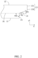
FIG. 2 is a schematic structural diagram of an adhesive member not bent according to another embodiment of this application. -
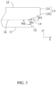
FIG. 3 is a schematic structural diagram of an adhesive member not bent according to another embodiment of this application. -
FIG. 4 is a schematic structural diagram of an adhesive member not bent according to another embodiment of this application. -
FIG. 5 is a schematic structural diagram of an adhesive member not bent according to another embodiment of this application. -
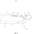
FIG. 6 is a schematic structural diagram of an adhesive member not bent according to another embodiment of this application. -
FIG. 7 is a schematic structural diagram of an adhesive member not bent according to another embodiment of this application. -
FIG. 8 is a schematic structural diagram of an adhesive member not bent according to another embodiment of this application. -
FIG. 9 is a schematic structural diagram of an adhesive member not bent according to another embodiment of this application. -
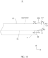
FIG. 10 is a schematic structural diagram of an adhesive member not bent according to another embodiment of this application. -
FIG. 11 is a schematic diagram of a partial structure of an electrochemical device according to an embodiment of this application. -
FIG. 12 is a schematic structural diagram of a housing before encapsulation according to an embodiment of this application. -
FIG. 13 is a schematic structural diagram of an electrochemical device being in a state according to an embodiment of this application. -
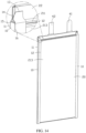
FIG. 14 is a schematic structural diagram of the electrochemical device being in another state according to an embodiment of this application. -
Electrochemical device 100 Adhesive member 10 First edge 11 Second edge 12 Third boundary line 121 Fourth boundary line 122 Fifth boundary line 123 Third edge 13 First end 131 Second end 132 First boundary line 14 Second boundary line 15 Crease 16 Fourth edge 17 Housing 20 Main body portion 21 First surface 211 Second surface 212 Third surface 213 First connection line 214 First sealing portion 22 Second sealing portion 23 First layer 24 Third layer 25 First folding portion 26 Second folding portion 27 Accommodation groove 28 Sealing portion 29 Electrode assembly 30 Positive electrode tab 41 Negative electrode tab 42 First direction X Second direction Y - This application is further described with reference to the accompanying drawings in the following specific embodiments.
- The following describes the technical solutions in some embodiments of this application with reference to the accompanying drawings in these embodiments of this application. Apparently, the described embodiments are only some rather than all embodiments of this application.
- It should be noted that when one component is assumed as being "connected to" another component, it may be connected to the another component directly or with a component possibly present therebetween. When one component is assumed as being "disposed on/in" another component, the component may be provided directly on/in the another component or with a component possibly present therebetween.
- Unless otherwise defined, all technical and scientific terms used herein shall have the same meanings as commonly understood by those skilled in the art to which this application pertains. The terms used herein in the specification of this application are intended to merely describe the specific embodiments rather than to limit this application.
- In this application, the term "parallel" is used to describe the ideal state between two components (edges or lines or surfaces). During actual production or use, an approximately parallel state may be present between the two components. For example, with reference to the description of numerical values, "parallel" may indicate that an included angle between two straight lines is within a range of 180°±10°, "parallel" may alternatively indicate that a dihedral angle of two planes is within a range of 180°±10°, and "parallel" may further alternatively indicate that an included angle between a straight line and a plane is within a range of 180°±10°. Two components described as "parallel" to each other may not be absolutely straight lines or planes, and may be approximately straight lines or planes. From a macro perspective, a component can be considered as a "straight line" or "plane" as long as the overall extension direction is a straight line or a plane.
- The term "perpendicular" is used to describe the ideal state between two components (edges or lines or surfaces). In actual production or use, an approximation of this perpendicular state can exist between two parts. For example, with reference to the description of numerical values, "perpendicular" may indicate that an included angle between two straight lines is within a range of 90°±10°, "perpendicular" may alternatively indicate that a dihedral angle of two planes is within a range of 90°±10°, and "perpendicular" may alternatively indicate that an included angle between a straight line and a plane is within a range of 90°±10°. Two components described as "perpendicular" to each other may not be absolutely straight lines or planes, and may be approximately straight lines or planes. From a macro perspective, a component can be considered as a "straight line" or "plane" as long as the overall extension direction is a straight line or a plane.
- An embodiment of this application provides an adhesive member, including a first edge, a second edge, a third edge, a first boundary line, and a second boundary line. The first edge is opposite the second edge, the third edge includes a first end and a second end opposite the first end, and the first end is connected to the second edge. Two ends of the second boundary line are respectively connected to the first boundary line and the first edge, and two ends of the first boundary line are respectively connected to the second boundary line and the second end. An included angle R1 is formed by a connection line between the two ends of the first boundary line and a connection line between two ends of the second boundary line, and 5°≤R1≤235°.
- With the included angle R1 formed by the first boundary line and the second boundary line, when the adhesive member is bonded to a cell, a crease corresponding to a side edge of the cell is located within the range of the first boundary line and the second boundary line, thereby reducing the risk of sharp corners generated when the adhesive member is pressed down on a surface of the cell, reducing the influence on the outer contour size of the cell, and further reducing the production cost.
- The following further describes some embodiments of this application with reference to the accompanying drawings.
- As shown in
FIG. 1 , Embodiment 1 of this application provides anadhesive member 10 which can be used to bond a pouch cell, providing insulation and protection. - The
adhesive member 10 includes afirst edge 11, asecond edge 12, athird edge 13, afirst boundary line 14, and asecond boundary line 15. Thefirst edge 11 is opposite thesecond edge 12, thethird edge 13 is connected to thesecond edge 12, thethird edge 13 is away from thefirst edge 11, two ends of thefirst boundary line 14 are respectively connected to thethird edge 13 and thesecond boundary line 15, and two ends of thesecond boundary line 15 are respectively connected to thefirst boundary line 14 and thefirst edge 11. Thethird edge 13 includes afirst end 131 and asecond end 132 opposite thefirst end 131. Thefirst end 131 is connected to thesecond edge 12, and thesecond end 132 is connected to thefirst boundary line 14. An included angle R1 is formed by a connection line between the two ends of thefirst boundary line 14 and a connection line between two ends of thesecond boundary line 15, and 5°≤R1≤235°. With the included angle R1 formed by thefirst boundary line 14 and thesecond boundary line 15, when theadhesive member 10 is bonded to a cell, theadhesive member 10 and a crease corresponding to a side edge of the cell is located within the range of thefirst boundary line 14 and thesecond boundary line 15, thereby reducing the risk of sharp corners generated when theadhesive member 10 is pressed down, reducing the influence on the outer contour size of the cell, and further reducing the production cost. In this application, the included angle R1 is an included angle that is formed as the connection line between the two ends of thefirst boundary line 14 intersects the connection line between the two ends of thesecond boundary line 15 and located outside theadhesive member 10. - Specifically, the value of the included angle R1 may be any one of 5°, 15°, 30°, 45°, 60°, 75°, 90°, 95°, 135°, 140°, 145°, 150°, 155°, 160°, 165°, 170°, 175°, 185°, 190°, 195°, 200°, 205°, 210°, 215°, 220°, 225°, 230°, and 235°.
- The
adhesive member 10 is made of an insulating material. In an embodiment, theadhesive member 10 includes an insulating adhesive tape. - In some embodiments, 30°≤R1<180°. When the
adhesive member 10 is bonded to the cell, theadhesive member 10 and the crease corresponding to the side edge of the cell are located within the range of thefirst boundary line 14 and thesecond boundary line 15. Theadhesive member 10 can attach to an exposed metal layer of the housing of the cell to provide insulation and protection. This can further reduce the risks of short circuit in the cell and sharp corners when the side edge of the cell is pressed down, further reducing the impact on the outer contour size of the cell, thus further reducing the production cost. In some other embodiments, 135°≤R1≤150°. In some other embodiments, 5°≤R1≤75°. - In an embodiment, the
first edge 11 and thesecond edge 12 are parallel to each other and both are parallel to a first direction X, the first direction X being the length direction of theadhesive member 10. In this application, the length direction of theadhesive member 10 is the extension direction of theadhesive member 10. - In an embodiment, an included angle R5 is formed by the connection line between the two ends of the
first boundary line 14 and the first direction X, and 5°≤R5≤60°. In an embodiment, 15°≤R5≤45°. Optionally, the value of the included angle R5 may be any one of 15°, 20°, 25°, 30°, 35°, 40°, and 45°. In this application, the included angle R5 is the smallest angle formed by the connection line between the two ends of thefirst boundary line 14 and the first direction X. - In an embodiment, an included angle R6 is formed by the connection line between the two ends of the
second boundary line 15 and the first direction X, and 15°≤R6≤180°. In this application, the included angle R6 is an included angle that is formed as the connection line between the two ends of thesecond boundary line 15 intersects the first direction X and located in theadhesive member 10. Optionally, the value of the included angle R6 may be any one of 15°, 20°, 25°, 30°, 35°, 40°, 45°, 50°, 55°, 60°, 70°, 80°, 90°, 100°, 120°, 135°, 150°, 165°, and 180°. - In an embodiment, 15°≤R6<90°, as shown in
FIG. 1 . In another embodiment, 90°≤R6≤180°. - As shown in
FIG. 2 , in another embodiment, R6=90°, and thesecond boundary line 15 is perpendicular to the first direction X and thefirst edge 11. - As shown in
FIG. 3 , in another embodiment, 90°<R6<180°. - As shown in
FIG. 4 , in another embodiment, R6=180°, and thesecond boundary line 15 is parallel to the first direction X and thefirst edge 11. Theadhesive member 10 further includes afourth edge 17, with two ends of thefourth edge 17 respectively connected to thesecond boundary line 15 and thefirst edge 11. - Further description is made using 15°≤R6<90° as an example.
- Still referring to
FIG. 1 , in an embodiment, along the first direction X, the length of thefirst boundary line 14 is d1, and d1>1 mm. In some embodiments, 1.5 mm≤d1≤3 mm. In this application, the length d1 is the perpendicular distance between the two ends of thefirst boundary line 14 along the first direction X. Optionally, the value of d1 may be any one of 1.5 mm, 2 mm, 2.5 mm, and 3 mm. - In an embodiment, along the second direction Y perpendicular to the first direction X, the length of the
second boundary line 15 is d2, and d2≥1 mm. In some embodiments, 1 mm≤d2≤5.5 mm. In this application, the length d2 is the perpendicular distance between the two ends of thesecond boundary line 15 along the second direction Y. Optionally, the value of d2 may be any one of 1mm, 1.5 mm, 2 mm, 2.5 mm, 3 mm, 3.5 mm, 4 mm, 4.5 mm, 5 mm, and 5.5 mm. - In an embodiment, the second direction Y is the width direction of the
adhesive member 10. In an embodiment, the connection line between thefirst end 131 and thesecond end 132 of thethird edge 13 is parallel to the second direction Y, and the connection line between thefirst end 131 and thesecond end 132 is perpendicular to thefirst edge 11 and thesecond edge 12. - In an embodiment, the
first boundary line 14 intersects thesecond boundary line 15 to form a structure concave to theadhesive member 10, as shown inFIG. 1 , and R1<180°. - As shown in
FIG. 5 , in an embodiment, thefirst boundary line 14 intersects thesecond boundary line 15 to form a structure convex from theadhesive member 10, and R1>180°. In an embodiment, along the first direction X, the intersection point of thefirst boundary line 14 and thesecond boundary line 15 is located between the intersection point of thefirst boundary line 14 and thethird edge 13, and the intersection point of thesecond boundary line 15 and thefirst edge 11. In another embodiment, along the first direction X, the intersection point of thefirst boundary line 14 and thesecond boundary line 15 extends beyond the third edge 13 (not shown in the figure). - As shown in
FIG. 6 , in an embodiment, thesecond edge 12 includes athird boundary line 121, afourth boundary line 122, and afifth boundary line 123 being connected sequentially. Two ends of thethird boundary line 121 are respectively connected to thefourth boundary line 122 and thefirst end 131, and two ends of thefourth boundary line 122 are respectively connected to thethird boundary line 121 and thefifth boundary line 123. In an embodiment, thefifth boundary line 123 is parallel to thefirst edge 11. - An included angle R2 is formed by the connection line between the two ends of the
third boundary line 121 and a connection line between the two ends of thethird edge 13, and 0°<R2<180°. In an embodiment, 30°≤R2≤150°. In an embodiment, 45°≤R2≤120°. In an embodiment, 60°≤R2≤120°. - Optionally, the value of the included angle R2 may be any one of 60°, 65°, 70°, 75°, 80°, 85°, 90°, 95°, 100°, 105°, 110°, 115°, and 120°.
- In an embodiment, an included angle R3 is formed between the connection line between the two ends of the
third boundary line 121 and a connection line between two ends of thefourth boundary line third boundary line 121 intersects the connection line between the two ends of thefourth boundary line 122, and located outside theadhesive member 10. - In an embodiment, 60°≤R3≤180°. In an embodiment, 90°≤R3≤180°. In an embodiment, 120°≤R3≤180°. Optionally, the value of the included angle R3 may be any one of 120°, 125°, 130°, 135°, 140°, 145°, 150°, 155°, 160°, 165°, 170°, 175°, and 180°.
- In an embodiment, an included angle R4 is formed by the connection line between the two ends of the
fourth boundary line 122 and a connection line between two ends of thefifth boundary line 123, and 0°<R4≤180°. In this application, the included angle R4 is an included angle formed as the connection line between the two ends of thefourth boundary line 122 intersects the connection line between the two ends of thefifth boundary line 123, and located in theadhesive member 10. - In an embodiment, 30°≤R4≤180°. In an embodiment, 60°≤R4≤150°. In an embodiment, 90°≤R4≤150°. Optionally, the value of the included angle R4 may be any one of 90°, 95°, 100°, 105°, 110°, 115°, 120°, 125°, 130°, 135°, 140°, 145°, and 150°.
- In an embodiment, an included angle R7 is formed by the connection line between the two ends of the
third boundary line 121 and the first direction X, and 0°≤R7≤90°. In an embodiment, 15°≤R7≤60°. In this application, the included angle R7 is the smallest angle formed by the connection line between the two ends of thethird boundary line 121 and the first direction X. Optionally, the value of the included angle R7 may be any one of 15°, 17°, 20°, 25°, 30°, 35°, 40°, 45°, 50°, 55°, and 60°. - In an embodiment, an included angle R8 is formed by the connection line between the two ends of the
fourth boundary line 122 and the first direction X, and 0°≤R8≤90°. In an embodiment, 13°≤R8≤60°. In this application, the included angle R8 is the smallest angle formed by the connection line between the two ends of thefourth boundary line 122 and the first direction X. Optionally, the value of the included angle R8 may be any one of 13°, 15°, 20°, 25°, 30°, 35°, 40°, 45°, 50°, 55°, and 60°. - In an embodiment, along the first direction X, the length of the
third boundary line 121 is d3, and d3≥1.5 mm. In some embodiments, 1.5 mm≤d3≤3 mm. In this application, the length d3 is the perpendicular distance between the two ends of thethird boundary line 121 along the first direction X. Optionally, the value of d3 may be any one of 1.5 mm, 2 mm, 2.5 mm, and 3 mm. - In an embodiment, d3=d1+0.5 mm.
- In an embodiment, along the second direction Y, the length of the
fourth boundary line 122 is d4, and d4≥1 mm. In this application, the length d4 is the perpendicular distance between the two ends of thefourth boundary line 122 along the second direction Y Optionally, the value of d3 may be any one of 1.5 mm, 2 mm, 2.5 mm, and 3 mm. - As shown in
FIG. 7 , in an embodiment, R1=128°, R5=20°, R6=72°, R2=73°, R3=150°, R7=17°, R8=13°, and R4=167°. Thefirst boundary line 14 intersects thesecond boundary line 15 to form a structure concave to theadhesive member 10. Thethird boundary line 121 intersects thefourth boundary line 122 to form a structure concave to theadhesive member 10. - As shown in
FIG. 8 , in an embodiment, R1=165°, R5=30°, R6=45°, R2=73°, R3=150°, R7=17°, R8=13°, and R4=167°. Thefirst boundary line 14 intersects thesecond boundary line 15 to form a structure concave to theadhesive member 10. Thethird boundary line 121 intersects thefourth boundary line 122 to form a structure concave to theadhesive member 10. - As shown in
FIG. 9 , in an embodiment, R1=128°, R5=20°, R6=72°, R2=73°, R3=73°, R7=17°, R8=90°, and R4=90°. Thefirst boundary line 14 intersects thesecond boundary line 15 to form a structure concave to theadhesive member 10. Thethird boundary line 121 intersects thefourth boundary line 122 to form a structure concave to theadhesive member 10, and thefourth boundary line 122 is perpendicular to thefifth boundary line 123. - As shown in
FIG. 10 , in an embodiment, R1=128°, R5=20°, R6=72°, R2=73°, R3=163°, R7=17°, R8=00°, and R4=180°. Thefirst boundary line 14 intersects thesecond boundary line 15 to form a structure concave to theadhesive member 10. Thethird boundary line 121 intersects thefourth boundary line 122 to form a structure concave to theadhesive member 10. In an embodiment, both thefourth boundary line 122 and thefifth boundary line 123 are parallel to thefirst edge 11. - As shown in
FIGs. 11 ,12 , and13 , Embodiment 2 of this application provides an electrochemical device 100 that can be used to store electrical energy and supply power to electrical equipment. The electrochemical device 100 includes ahousing 20, anelectrode assembly 30, a tab, and theadhesive member 10 according to Embodiment 1. Theelectrode assembly 30 is accommodated in thehousing 20, and the tab has one end connected to theelectrode assembly 30 and another end extending beyond of thehousing 20. Theadhesive member 10 is bonded to a surface of thehousing 20. - The
housing 20 includes amain body portion 21, afirst sealing portion 22, and asecond sealing portion 23. Theelectrode assembly 30 is accommodated in themain body portion 21. Thefirst sealing portion 22 and thesecond sealing portion 23 extend beyond the surface of themain body portion 21, and the tab extends beyond thehousing 20 from thefirst sealing portion 22. - The
electrode assembly 30 includes a positive electrode plate, a negative electrode plate, and a separator. The separator is placed between the positive electrode plate and the negative electrode plate. The positive electrode plate, the separator, and the negative electrode plate are stacked or wound. - The tab includes a
positive electrode tab 41 and anegative electrode tab 42. Thepositive electrode tab 41 has one end connected to the positive electrode plate and another end extending beyond thehousing 20. Thenegative electrode tab 42 has one end connected to the negative electrode plate and another end extending beyond thehousing 20. - The
main body portion 21 has afirst surface 211, asecond surface 212, and athird surface 213 being connected to each other. Thefirst sealing portion 22 extends beyond thefirst surface 211, and thesecond sealing portion 23 extends beyond thesecond surface 212 and bends towards thethird surface 213. In an embodiment, thesecond sealing portion 23 is attached to thesecond surface 212. - The
first edge 11 of theadhesive member 10 is attached to a side of thesecond sealing portion 23 back away from thesecond surface 212, thesecond edge 12 is attached to thethird surface 213, and thethird edge 13 bends towards thefirst sealing portion 22 from thethird surface 213 to be attached to thefirst surface 211 and/or thefirst sealing portion 22. - In an embodiment, before the electrochemical device 100 is packaged, the
housing 20 includes afirst folding portion 26 and asecond folding portion 27, at least one of which is provided with anaccommodation groove 28 for accommodating theelectrode assembly 30. Theelectrode assembly 30 is accommodated in theaccommodation groove 28, and thefirst folding portion 26 and thesecond folding portion 27 are folded and connected to form themain body portion 21 and a sealingportion 29. The sealingportion 29 extends outwards from the surface of themain body portion 21 and includes thefirst sealing portion 22 and thesecond sealing portion 23. - In an embodiment, the
housing 20 is a composite layered structure, including afirst layer 24, a second layer (not shown in the figure), and athird layer 25. The second layer is located between thefirst layer 24 and thethird layer 25. Thefirst layer 24 forms the inner surface of thehousing 20, and thethird layer 25 forms the outer surface of thehousing 20. In an embodiment, thefirst layer 24 and the second layer are connected by a binder, and the second layer and thethird layer 25 are connected by a binder. - In an embodiment, the material of the
first layer 24 includes but is not limited to polypropylene. In an embodiment, thefirst layer 24 features corrosion resistance to electrolyte. - In an embodiment, the material of the second layer is metal, including but not limited to aluminum and steel.
- In an embodiment, the material of the
third layer 25 includes but is not limited to nylon. In an embodiment, thethird layer 25 protects the second layer, reducing the risk of the second layer being scratched or punctured. - In an embodiment, the end surface of the
second sealing portion 23 away from themain body portion 21 exposes the second layer, which increases the risk of short circuit in the electrochemical device 100. Thefirst edge 11 of theadhesive member 10 is attached to thesecond sealing portion 23, and thesecond edge 12 is attached to thethird surface 213, covering the exposed second layer at the end of thesecond sealing portion 23, thereby reducing the risk of short circuit in the electrochemical device 100. - In an embodiment, the
housing 20, theelectrode assembly 30, and the tab form a pouch cell. - Referring to
FIGs. 1 ,11 ,13 , and14 , in an embodiment, thesecond surface 212 intersects thethird surface 213 at thefirst connection line 214, and theadhesive member 10 has acrease 16, with thecrease 16 being opposite thefirst connection line 214. - In an embodiment, the
crease 16 intersects an intersection point of thefirst boundary line 14 and thesecond boundary line 15. In an embodiment, thecrease 16 intersects thefirst boundary line 14. In an embodiment, thecrease 16 intersects thesecond boundary line 15. Thecrease 16 intersects thefirst boundary line 14 and/or thesecond boundary line 15, such that when thefirst edge 11 is attached to a side of thesecond sealing portion 23 back away from thesecond surface 212, theadhesive member 10 can cover the exposed second layer of thesecond sealing portions 23, thereby reducing the risk of short circuit in the electrochemical device 100. - In an embodiment, the
crease 16 is parallel to thefirst edge 11. - In an embodiment, at least part of the
adhesive member 10 extends beyond thefirst surface 211, the part of theadhesive member 10 extending beyond thefirst surface 211 bends towards thefirst sealing portion 22, and thethird edge 13 is attached to thefirst surface 211 and/or thefirst sealing portion 22. - In an embodiment, when the
first boundary line 14 intersects thesecond boundary line 15 to form a structure concave to theadhesive member 10. Preferably, thecrease 16 intersects an intersection point of thefirst boundary line 14 and thesecond boundary line 15. - In an embodiment, the
first boundary line 14 intersects thesecond boundary line 15 to form a structure convex from theadhesive member 10, and thecrease 16 intersects thesecond boundary line 15, as shown inFIG. 2 . - In an embodiment, the thickness of the electrochemical device 100 is D1, and d2≤110%*D1, such that the part of the
adhesive member 10 between thecrease 16 and thefirst edge 11 can be stably bonded to thesecond surface 212 and thesecond sealing portion 23, reducing the risk of theadhesive member 10 peeling off. - In an embodiment, the length of the
first sealing portion 22 extending beyond thefirst surface 211 is D2, d1≤D2, and d3≤D2, such that the part of theadhesive member 10 extending beyond thefirst surface 211 can be stably bonded to thefirst surface 211 and/or thefirst sealing portion 22, reducing the risk of theadhesive member 10 peeling off. - In an embodiment, the width of the electrochemical device 100 is D3, and d4≤D3, such that the part of the
adhesive member 10 between thecrease 16 and thesecond edge 12 can be stably adhered to thethird surface 213, reducing the risk of theadhesive member 10 peeling off. - In an embodiment, the
main body portion 21 further includes a fourth surface (not shown in the figure), which is opposite thesecond surface 212 and connects thefirst surface 211 and thethird surface 213. Thehousing 20 further includes a third sealing portion (not shown in the figure), which extends beyond the fourth surface and bends towards thethird surface 213. The electrochemical device 100 includes twoadhesive members 10. Thefirst edge 11 of oneadhesive member 10 is attached to thesecond sealing portion 23, thefirst edge 11 of the otheradhesive member 10 is attached to the fourth sealing portion, and thesecond edge 12 of the otheradhesive member 10 is attached to thethird surface 213. Theadhesive members 10 are attached to thehousing 20 in the same manner, which is not elaborated herein. - In an embodiment, the
second sealing portion 23 extends beyond thefirst surface 211 and bends towards thethird surface 213, with the part extending beyond thefirst surface 211 bending towards thefirst surface 211. In an embodiment, thethird edge 13 is partially attached to thefirst surface 211, to thesecond sealing portion 23 located on thefirst surface 211, and to thefirst sealing portion 22. In an embodiment, thethird edge 13 is partially attached to thesecond sealing portion 23 located on thefirst surface 211 and to thefirst sealing portion 22. - In addition, persons skilled in the art can also make other changes within the spirit of this application. Certainly, these changes made according to the spirit of this application shall fall within the scope of this application.
Claims (12)
- An adhesive member, comprising a first edge, a second edge, and a third edge, wherein the first edge is opposite to the second edge, the third edge comprises a first end and a second end opposite to the first end, the first end is connected to the second edge, and further comprising:a first boundary line; anda second boundary line, wherein two ends of the second boundary line are respectively connected to the first boundary line and the first edge, and two ends of the first boundary line are respectively connected to the second boundary line and the second end;wherein an included angle R1 is formed by a connection line between the two ends of the first boundary line and a connection line between two ends of the second boundary line, and 5°≤R1≤235°.
- The adhesive member according to claim 1, wherein 135°≤R1<180°.
- The adhesive member according to claim 1, wherein the second edge comprises a third boundary line, a fourth boundary line, and a fifth boundary line, and the third boundary line, the fourth boundary line, and the fifth boundary line being connected sequentially, two ends of the third boundary line are respectively connected to the fourth boundary line and the first end, an included angle R2 is formed by a connection line between the two ends of the third boundary line and a connection line between two ends of the third edge, and 0°<R2<180°.
- The adhesive member according to claim 3, wherein 30°≤R2≤150°.
- The adhesive member according to claim 3, wherein an included angle R3 is formed by the connection line between the two ends of the third boundary line and a connection line between two ends of the fourth boundary line, and 30°≤R3≤180°.
- The adhesive member according to claim 5, wherein 60°≤R3≤180°.
- The adhesive member according to claim 3, wherein an included angle R4 is formed by the connection line between the two ends of the fourth boundary line and a connection line between two ends of the fifth boundary line, and 0°<R4≤180°.
- The adhesive member according to claim 7, wherein 30°≤R4≤180°.
- The adhesive member according to claim 1, wherein an included angle R5 is formed by the connection line between the two ends of the first boundary line and a first direction, and 5°≤R5≤60°, the first direction being a length direction of the adhesive member.
- The adhesive member according to claim 1, an included angle R6 is formed by the connection line between the two ends of the second boundary line and a first direction, and 15°≤R6≤180°, the first direction being a length direction of the adhesive member.
- An electrochemical device, comprising:a housing comprising a main body portion, a first sealing portion, and a second sealing portion, wherein the first sealing portion and the second sealing portion are both connected to the main body portion, the main body portion has a first surface, a second surface, and a third surface being connected to each other, the first sealing portion extends beyond the first surface, and the second sealing portion extends beyond the second surface and bends towards the third surface;an electrode assembly accommodated in the main body portion; anda tab, wherein one end of the tab connecting to the electrode assembly and another end of the tab extending beyond the housing from the first sealing portion;wherein the electrochemical device further comprises the adhesive member according to any one of claims 1 to 10, the first edge is attached to a side of the second sealing portion back away from the second surface, the second edge is attached to the third surface, and the third edge is attached to the first surface and/or the first sealing portion.
- The electrochemical device according to claim 11, whereinthe second surface intersects the third surface at the first connection line;the adhesive member has a crease, the crease being opposite the first connection line; andthe crease intersects the first boundary line or an intersection point between the first boundary line and the second boundary line.
Applications Claiming Priority (1)
| Application Number | Priority Date | Filing Date | Title |
|---|---|---|---|
| PCT/CN2022/084654 WO2023184433A1 (en) | 2022-03-31 | 2022-03-31 | Adhesive member and electrochemical device |
Publications (2)
| Publication Number | Publication Date |
|---|---|
| EP4489191A1 true EP4489191A1 (en) | 2025-01-08 |
| EP4489191A4 EP4489191A4 (en) | 2025-04-09 |
Family
ID=87283032
Family Applications (1)
| Application Number | Title | Priority Date | Filing Date |
|---|---|---|---|
| EP22934270.4A Pending EP4489191A4 (en) | 2022-03-31 | 2022-03-31 | Adhesive member and electrochemical device |
Country Status (4)
| Country | Link |
|---|---|
| US (1) | US20250023164A1 (en) |
| EP (1) | EP4489191A4 (en) |
| CN (1) | CN115956320B (en) |
| WO (1) | WO2023184433A1 (en) |
Family Cites Families (7)
| Publication number | Priority date | Publication date | Assignee | Title |
|---|---|---|---|---|
| JP6264165B2 (en) * | 2014-04-09 | 2018-01-24 | 株式会社豊田自動織機 | Battery unit manufacturing method and battery unit |
| CN205122651U (en) * | 2015-11-02 | 2016-03-30 | 宁德新能源科技有限公司 | Soft -packed lithium ion battery |
| KR101950464B1 (en) * | 2015-11-30 | 2019-02-20 | 주식회사 엘지화학 | Battery Cell of Irregular Structure with Improved Sealing Reliability of Cell Case |
| CN212810347U (en) * | 2020-06-30 | 2021-03-26 | 宁德新能源科技有限公司 | Electrochemical device and electronic device including the same |
| CN114284539B (en) * | 2020-09-18 | 2024-06-11 | 宁德新能源科技有限公司 | Battery |
| CN113363641B (en) * | 2021-05-25 | 2024-07-09 | 宁德新能源科技有限公司 | Soft-pack battery cell, method for manufacturing shell of soft-pack battery cell, and electric device |
| CN113422161A (en) * | 2021-06-09 | 2021-09-21 | 宁德新能源科技有限公司 | Electrochemical device and electronic device |
-
2022
- 2022-03-31 EP EP22934270.4A patent/EP4489191A4/en active Pending
- 2022-03-31 CN CN202280005382.XA patent/CN115956320B/en active Active
- 2022-03-31 WO PCT/CN2022/084654 patent/WO2023184433A1/en not_active Ceased
-
2024
- 2024-09-27 US US18/899,318 patent/US20250023164A1/en active Pending
Also Published As
| Publication number | Publication date |
|---|---|
| EP4489191A4 (en) | 2025-04-09 |
| US20250023164A1 (en) | 2025-01-16 |
| WO2023184433A8 (en) | 2024-11-21 |
| WO2023184433A1 (en) | 2023-10-05 |
| CN115956320A (en) | 2023-04-11 |
| CN115956320B (en) | 2025-03-18 |
Similar Documents
| Publication | Publication Date | Title |
|---|---|---|
| CN209592206U (en) | Secondary cell | |
| US20210126325A1 (en) | Secondary battery, apparatus and manufacturing method for secondary battery | |
| US12176552B2 (en) | Battery cell having internal protective layer, and electric device | |
| US20200075992A1 (en) | Methods and configurations for battery cell packaging | |
| US11315744B2 (en) | Electric storage device | |
| EP4604280A1 (en) | Packaging bag, battery cell, and electrical device | |
| US7635538B2 (en) | Battery | |
| CN104852012A (en) | Electrochemical cell | |
| JP6690831B2 (en) | Secondary battery | |
| CN117791053A (en) | Batteries and electrical equipment | |
| EP2840624B1 (en) | Pouch type rechargeable battery | |
| US20250023164A1 (en) | Adhesive member and electrochemical device | |
| US10879016B2 (en) | Electrochemical device and method for manufacturing same | |
| EP3624209A1 (en) | Battery | |
| EP4525147A2 (en) | Secondary battery and electronic apparatus | |
| EP2840625A1 (en) | Pouch type rechargeable battery | |
| WO2025108269A1 (en) | Cell and battery | |
| CN219892359U (en) | Battery and electronic equipment | |
| US20230420809A1 (en) | Battery and battery module | |
| US20230420808A1 (en) | Battery | |
| CN121840026A (en) | Battery and terminal device | |
| CN217589341U (en) | Connecting sheet and bridging device for battery interior and battery | |
| EP4478499A1 (en) | Electrochemical apparatus and electrical device | |
| KR20190132140A (en) | Battery Pack | |
| KR102821357B1 (en) | Rechargeable battery |
Legal Events
| Date | Code | Title | Description |
|---|---|---|---|
| STAA | Information on the status of an ep patent application or granted ep patent |
Free format text: STATUS: THE INTERNATIONAL PUBLICATION HAS BEEN MADE |
|
| PUAI | Public reference made under article 153(3) epc to a published international application that has entered the european phase |
Free format text: ORIGINAL CODE: 0009012 |
|
| STAA | Information on the status of an ep patent application or granted ep patent |
Free format text: STATUS: REQUEST FOR EXAMINATION WAS MADE |
|
| 17P | Request for examination filed |
Effective date: 20240930 |
|
| AK | Designated contracting states |
Kind code of ref document: A1 Designated state(s): AL AT BE BG CH CY CZ DE DK EE ES FI FR GB GR HR HU IE IS IT LI LT LU LV MC MK MT NL NO PL PT RO RS SE SI SK SM TR |
|
| A4 | Supplementary search report drawn up and despatched |
Effective date: 20250310 |
|
| RIC1 | Information provided on ipc code assigned before grant |
Ipc: H01M 50/557 20210101ALI20250304BHEP Ipc: H01M 50/55 20210101ALI20250304BHEP Ipc: H01M 50/178 20210101ALI20250304BHEP Ipc: H01M 50/186 20210101ALI20250304BHEP Ipc: H01M 50/105 20210101ALI20250304BHEP Ipc: H01M 50/184 20210101AFI20250304BHEP |
|
| DAV | Request for validation of the european patent (deleted) | ||
| DAX | Request for extension of the european patent (deleted) |