EP4489181A1 - Energiespeichersystem mit wiederaufladbaren batteriemodulen - Google Patents
Energiespeichersystem mit wiederaufladbaren batteriemodulen Download PDFInfo
- Publication number
- EP4489181A1 EP4489181A1 EP24186198.8A EP24186198A EP4489181A1 EP 4489181 A1 EP4489181 A1 EP 4489181A1 EP 24186198 A EP24186198 A EP 24186198A EP 4489181 A1 EP4489181 A1 EP 4489181A1
- Authority
- EP
- European Patent Office
- Prior art keywords
- battery
- module
- accumulator
- elements
- energy storage
- Prior art date
- Legal status (The legal status is an assumption and is not a legal conclusion. Google has not performed a legal analysis and makes no representation as to the accuracy of the status listed.)
- Pending
Links
Images


Classifications
-
- H—ELECTRICITY
- H01—ELECTRIC ELEMENTS
- H01M—PROCESSES OR MEANS, e.g. BATTERIES, FOR THE DIRECT CONVERSION OF CHEMICAL ENERGY INTO ELECTRICAL ENERGY
- H01M50/00—Constructional details or processes of manufacture of the non-active parts of electrochemical cells other than fuel cells, e.g. hybrid cells
- H01M50/20—Mountings; Secondary casings or frames; Racks, modules or packs; Suspension devices; Shock absorbers; Transport or carrying devices; Holders
- H01M50/204—Racks, modules or packs for multiple batteries or multiple cells
- H01M50/207—Racks, modules or packs for multiple batteries or multiple cells characterised by their shape
- H01M50/213—Racks, modules or packs for multiple batteries or multiple cells characterised by their shape adapted for cells having curved cross-section, e.g. round or elliptic
-
- H—ELECTRICITY
- H01—ELECTRIC ELEMENTS
- H01M—PROCESSES OR MEANS, e.g. BATTERIES, FOR THE DIRECT CONVERSION OF CHEMICAL ENERGY INTO ELECTRICAL ENERGY
- H01M10/00—Secondary cells; Manufacture thereof
- H01M10/42—Methods or arrangements for servicing or maintenance of secondary cells or secondary half-cells
- H01M10/4207—Methods or arrangements for servicing or maintenance of secondary cells or secondary half-cells for several batteries or cells simultaneously or sequentially
-
- H—ELECTRICITY
- H01—ELECTRIC ELEMENTS
- H01M—PROCESSES OR MEANS, e.g. BATTERIES, FOR THE DIRECT CONVERSION OF CHEMICAL ENERGY INTO ELECTRICAL ENERGY
- H01M10/00—Secondary cells; Manufacture thereof
- H01M10/42—Methods or arrangements for servicing or maintenance of secondary cells or secondary half-cells
- H01M10/425—Structural combination with electronic components, e.g. electronic circuits integrated to the outside of the casing
-
- H—ELECTRICITY
- H01—ELECTRIC ELEMENTS
- H01M—PROCESSES OR MEANS, e.g. BATTERIES, FOR THE DIRECT CONVERSION OF CHEMICAL ENERGY INTO ELECTRICAL ENERGY
- H01M50/00—Constructional details or processes of manufacture of the non-active parts of electrochemical cells other than fuel cells, e.g. hybrid cells
- H01M50/50—Current conducting connections for cells or batteries
- H01M50/572—Means for preventing undesired use or discharge
- H01M50/574—Devices or arrangements for the interruption of current
-
- H—ELECTRICITY
- H01—ELECTRIC ELEMENTS
- H01M—PROCESSES OR MEANS, e.g. BATTERIES, FOR THE DIRECT CONVERSION OF CHEMICAL ENERGY INTO ELECTRICAL ENERGY
- H01M10/00—Secondary cells; Manufacture thereof
- H01M10/42—Methods or arrangements for servicing or maintenance of secondary cells or secondary half-cells
- H01M10/425—Structural combination with electronic components, e.g. electronic circuits integrated to the outside of the casing
- H01M2010/4271—Battery management systems including electronic circuits, e.g. control of current or voltage to keep battery in healthy state, cell balancing
-
- H—ELECTRICITY
- H01—ELECTRIC ELEMENTS
- H01M—PROCESSES OR MEANS, e.g. BATTERIES, FOR THE DIRECT CONVERSION OF CHEMICAL ENERGY INTO ELECTRICAL ENERGY
- H01M2200/00—Safety devices for primary or secondary batteries
-
- Y—GENERAL TAGGING OF NEW TECHNOLOGICAL DEVELOPMENTS; GENERAL TAGGING OF CROSS-SECTIONAL TECHNOLOGIES SPANNING OVER SEVERAL SECTIONS OF THE IPC; TECHNICAL SUBJECTS COVERED BY FORMER USPC CROSS-REFERENCE ART COLLECTIONS [XRACs] AND DIGESTS
- Y02—TECHNOLOGIES OR APPLICATIONS FOR MITIGATION OR ADAPTATION AGAINST CLIMATE CHANGE
- Y02E—REDUCTION OF GREENHOUSE GAS [GHG] EMISSIONS, RELATED TO ENERGY GENERATION, TRANSMISSION OR DISTRIBUTION
- Y02E60/00—Enabling technologies; Technologies with a potential or indirect contribution to GHG emissions mitigation
- Y02E60/10—Energy storage using batteries
Definitions
- the present invention relates to the technical sector of battery energy storage systems. More specifically, it relates to an energy storage system with rechargeable battery-modules and to the methods to operate the system.
- an energy storage system (EES - Energy Storage System) is a system designed for storing electric energy upon charging, preserving it for a more or less long time in some way, in order to give it back more or less integrally whenever so requested. Substantially, such a system allows to separate electric energy generation from its use over time.
- the battery energy storage systems are a subsystem of the energy storage systems (ESS).
- the battery energy storage systems offer many advantages in terms of capacity, charging and discharging speeds, energy density, safety, and overall cost.
- a battery energy storage system comprises a casing containing a plurality of batteries (the present standard uses lithium-iron phosphate (LiFePo4) batteries) designed for storing electricity.
- BESS battery energy storage systems
- the battery energy accumulators use an electronic component, namely a Battery Management System or BMS, to control the status of the batteries accommodated in the accumulator; parameters like electrochemical cell temperature, voltage, peak value, charging status, etc., can be monitored and, in the presence of abnormal data, an alarm or another control/action is activated and the BMS breaks the electrical flow.
- BMS Battery Management System
- the batteries of the BESS accumulators known do not use any swap system (like those mainly used in the automotive market for fast recharging of vehicles, not in that of stationary energy storage) and feature the following disadvantages:
- fire prevention means is known between the cell packs, by using fire resistant devices complete with an explosion-proof device; these devices might also be equipped with suppression/extinguishment components.
- Interchangeable battery systems are known in the present status of the art wherein the batteries connected in series to each other are equipped with control systems (BMS) closed inside a casing and electrically interfaced to each other via different types of connectors, usually rated for power levels not exceeding than 100 A.
- BMS control systems
- Document TWI423140B illustrates an anti-counterfeiting battery pack and a respective authentication system, comprising battery cores provided with an internal identification unit and an external one, each complete with a first and a second reader of an authentication apparatus in order to read, compare, and calculate a first and a second inspection codes and to determine whether the core of the battery is an original product or not. Also, since every body of the battery core is provided with internal identification units and is sealed and protected by a protective coating, every battery core is hard to tamper.
- Document TWI308406B illustrates a battery pack that includes several power bus lines which connect a plurality of battery strings in parallel, wherein every battery string has several batteries connected in series to each other; also, the battery pack has several conductors which provide electrical communication facilities between the battery strings, so that a battery in one battery string is connected in parallel to a battery in other battery strings.
- Document US10763481 B2 describes improvements in the structural components and in the physical characteristics of the lithium batteries subjected to determined phenomena related to short-circuits and, consequently, subjected to high temperatures and to combustion; these improvements comprise the use of thin metallized (for example aluminium and/or copper) current collectors, materials and combinations thereof featuring a high shrinkage rate, materials that become nonconductive when exposed to high temperatures. Such improvements make it possible to withstand given defects (formation of dendrites, unexpected electrical overvoltage, etc.) inside a target lithium battery through the provision of an internal fuse, apparently internally to the considered lithium batteries themselves, which prevents undesired high temperature results caused by short-circuits.
- defects formation of dendrites, unexpected electrical overvoltage, etc.
- Document US2016254576A1 illustrates an accumulator that comprises batteries electrically connected to each other, wherein every battery comprises individual electrochemical cells; each of the electrolytical cells being thermally insulated from the others.
- Each of said electrochemical cells includes a monitoring device configured for electrically separating it from the others if at least one measured value, as monitored by a monitoring device, is outside a predetermined range of values.
- Document CN109417155A illustrates a short-circuit protection device for a battery monitoring system, provided with a battery pack comprising a plurality of electrolytic cells, a battery monitoring device for assessing the battery voltage, and a plurality of electrical wires which connect the battery and the battery monitoring device, formed of one portion designed for elution, wherein an insulating coating is detached in a median zone along the longitudinal direction, and a cored wire is exposed. Whenever the portion designed for elution is dipped into an electrolyte, the portion designed for elution (6) is eluted in the electrolyte and melted.
- a general object of the present invention is to provide a rechargeable module battery pack, each module being provided with the most sophisticated safety technologies, irrespective of the system dimensions, and acting in a passive or active manner directly from the inside of the accumulator.
- Another object of the present invention is to provide a battery energy storage system that can support big amounts of current and prevent outbreaks of fire internally to the BESS energy accumulators while assuring an immediate recovery.
- a further object of the present invention is to provide a battery energy storage system that can be integrated inside to the battery pack of a BESS accumulator by interacting therewith, via an external electric system.
- Another object of the present invention is to provide a battery energy storage system whereby it is possible to maintain and/or replace an individual cell that is defective or damaged, if any.
- a further object of the present description is to provide some methods to operate for the energy storage systems using rechargeable separated battery-modules, as set forth in claims 13 thru 17.
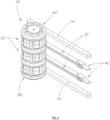
- Figure 1 shows one preferred, but not limitative, embodiment of an energy storage system 1 with rechargeable battery-modules according to the present invention.
- the system 1 is shown operationally coupled with an accumulator 10 formed of three rechargeable battery-modules 20 stacked onto each other, provided with metal bar contactors 30, 50 and switch devices 40.
- Said storage system 1 can be designed and configured for being operationally coupled with stationary storage systems for use in residential structures, productive activities, catering activities, or hotels; the same system can be installed inside electrical vehicles for managing interchangeable batteries, in the perspective of a 100% sustainable electric mobility.
- the energy storage system 1 with rechargeable battery-modules is provided with electrical connection and control means capable of supporting big amounts of currents in excess of 100A.
- the stacked battery-modules 20 are connected to bar contactors 30, 50 connected to output terminals, which are in turn connected to an inverter; the circuit is opened or closed by a shunt-coil 13 which receives power from a control and management device (BMS) 12, designed and configured for triggering a flow of current in the accumulator and, in case of malfunction, triggers a chain action which finally results in opening a switch device 40.
- BMS control and management device
- the switch device 40 of the energy storage system is designed and configured for triggering a flow of current between the stacked battery-modules 20 and a processing module 14, which is operationally connected to the BMS 12; the processing module 14 is programmed and configured for interfacing to sensors, actuators, and other components contained in the individual battery-modules that contain the cells and the electrical components connected in parallel. More in general, the module 14 is responsible for monitoring every battery module individually.
- Another object of the processing module 14 is to operate the various devices which every battery-module 20 can be equipped with, such as, for instance: a self-extinguishing device, a valve, a turbine for moving fluids, sensors, devices for electrical detaching according to a particularly advantageous embodiment, the processing module 14 is programmed and configured for operating a self-extinguishing device.
- the system 1 being connected to its respective slot of the accumulator 10 it is possible to exchange information and controls with each individual multiple-cell battery-module 20: this feature makes it possible to develop strategies of use and intervention directly with each individual battery-module.
- the switch devices 40 are activated to allow for a serial connection and the subsequent use of the accumulator.
- the processing module 14 can activate one or more turbines for making a liquid internal to the battery-module flow, so as to bring the temperature down to acceptable levels.
- the self-extinguishing module can autonomously activate itself so as to make the compromised battery-module safe.
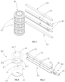
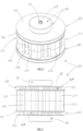
- the accumulator 10 illustrated in the axonometric views of figures 2 and 3 , applied to the intermediate bar contactors 30 and to the upper/lower bar contactors 50 respectively ( figure 2 ) and before the application to said contactors ( figure 3 ), comprises three electrically separated and rechargeable battery-modules 20, each containing a set of electrochemical cells 100; as shown here, said battery-modules 20 are stacked and are applied to said contactors 30 and 50 in a removable manner.
- the function of the bar contactors 50 is to allow a flow of current value in excess of 100A, in order to exploit the battery-module at the best, the function of the intermediate bar contactors 30 is that of isolating every battery-module from the serial connection through the operation of the switch device 40; this allows to take out, insert, and move each individual battery-module 20 in a fully safe manner, without any risks of sparks, accidental short-circuits, or electrocution for the operator, as typical with sliding contacts.
- Figures 6 and 7 show an axonometric view and a side view respectively, and figure 8 is an exploded view of a multiple-cell battery-module 20.
- Every battery-module 20 features an almost cylindrical shape and comprises two elements, namely an upper element 21, forming a cover, and a lower element 22, forming a base, superimposable to and fitting with each other in such a way as to form a cylindrical box-shaped casing for accommodating a set of electrochemical cells 100.
- a number of coaxial through holes namely upper through holes 213 and lower through holes 223 respectively, are cut in the upper circular surface 210 of the upper element 21 and in the lower circular surface 220 of the lower element 22, to form seats for the electrochemical cells 100 inserted in the casing 21, 22 of the battery-module 20.
- the side surfaces 211 and 221, of the upper element 21 and of the lower element 22 respectively, make up a containment grid which allows to align the cells with said through holes 213, 223 and the contact with the circular surfaces 63 of every programmed-deformability element 60, provided with a central through hole 61, forming a lower and upper terminal in every battery-module 20.
- Every programmed-deformability element 60 also comprises a second circular surface 62, coaxial to the circular surface 63 designed for an electrical connection of the battery-modules; a deformable conductive material 64 is interposed between the surfaces 62, 63.
- Pins 212, 222 are connected on the circular surfaces 210, 220, of the upper element 21 and of the lower element 22 respectively, for locking the box-shaped casing 21, 22 of the battery-module 20, once closed.
- a self-extinguishing device 110 having the same size and shape as the electrochemical cells 100, is present inside the multiple-cell battery-module 20, in an offset position.
- the self-extinguishing device 110 comprises a container element, for example a bivalve-type one, provided with drainage holes for an extinguishing or fire retardant expansion foam 90, inside which there are present two or more chemical elements contained in plastic bags specifically reserved for this purpose; a heating element is positioned in the middle of the device which, once activated, determines a collapse of the chemical element containers, whose subsequent mixing triggers a chemical reaction, which produces an extinguishing or flame retardant foam which, thanks to its own physical characteristics, expands and produces a pressure sufficient to deform the programmed-deformability elements 60, which operate as terminals, and a subsequent electrical detachment of the cells 100.
- a container element for example a bivalve-type one, provided with drainage holes for an extinguishing or fire retardant expansion foam 90, inside which there are present two or more chemical elements contained in plastic bags specifically reserved for this purpose
- a heating element is positioned in the middle of the device which, once activated, determines a collapse of the chemical
- Two further circular elements 70 made of a deformable elastic material, provided with central through holes 71, and operating a deformable means for easing up or performing the functions of the element 60 in the case of a malfunction, are superimposed above and below the two programmed-deformability elements 60 in every multiple-cell battery-module 20 (in the example depicted in figures 2 and 3 , above and below the central battery-module) coaxially thereto.
- Each of the two elements 70 having a diameter smaller than that of the element 60, is made of an insulating rubbery material rated for warranting a correct operating pressure on the cells 100 and maximum deformability whenever the self-extinguishing device is activated; this way, system effectiveness and removal of every element 60 away from the cells 100 are warranted under the action of the extinguishing or flame retardant foam 90.
- a cylindrical pin 23 passing through said central through holes 61, 71 holds the elements 21, 22 of the casing, the programmed-deformability elements 60, and the elements made of a deformable elastic material 70 that make up the multiple-cell battery-module 20, coaxially connected to each other to form a pack, which further two multiple-cell battery-modules 20 are coaxially stacked and connected to, so as to form the three stacked battery-module accumulator illustrated in figures 2 and 3 .
- Figure 4 shows an exploded axonometric view of one of the two elements 80 superimposed to the stacked battery-modules 20 above and below; said element 80 comprises a first plate 81, provided with through holes 811 forming gripping points for the accumulator 10 for its transportation, and a central through hole 812 for inserting the cylindrical pin 23, and a second plate 82 provided with through holes 821 coaxial to said through holes 811, also necessary to form a gripping point for the accumulator 10.
- Figure 5 shows an exploded axonometric view of an intermediate bar contactor 30, consisting of two metal bar semi-contactors 31 made of a conductive material, for example aluminium, provided with through holes 33 at the two ends for the electrical links or the connection to the switch devices 41; a bar 32, made of an insulating deformable material, is interposed in an intermediate position with respect to said bar semi-contactors 31, designed for preventing any current flow between the two metal bars 31.
- a bar 32 made of an insulating deformable material
- the device 40 operates as a switch to trigger a current flow in every bar contactor 30; this allows to temporarily connect the battery-modules in series to each other and to allow supply of the specified voltage and current.
- the switch device 40 allows an exchange of information with the Battery Management System (BMS) 12, as necessary to control the accumulator parameters.
- BMS Battery Management System
- Every upper/lower bar contactor 50 is formed of a metal bar made of a conductive material, for example aluminium, provided with through holes 51 at the two ends.
- the circular seats of the accumulator formed between the programmed-deformability elements 60 and the elements made of a deformable elastic material 70 form seats for a tangential insertion and connection of the bar contactors 30, 50 with the accumulator 10.
- the system according to the present invention supports two operating steps featuring a different configuration of the connections: namely, an accumulator charging step, and an accumulator discharging step.
- the switch device 40 is open and in this configuration the battery-modules of the accumulator are electrically separated: the positive-charge bar contactors, for example the semi-contactors 311, 313, and the contactor 502 are physically independent of the negative charge contactors, for example the semi-contactors 312, 314 and the contactor 501; this way, it is possible to recharge each individual battery-module or group of battery-modules, depending on the accumulator's size, in parallel.
- the positive-charge bar contactors for example the semi-contactors 311, 313, and the contactor 502 are physically independent of the negative charge contactors, for example the semi-contactors 312, 314 and the contactor 501; this way, it is possible to recharge each individual battery-module or group of battery-modules, depending on the accumulator's size, in parallel.
- This configuration allows to multiply the current input to the accumulator while using lower voltages, so as to warranty an accumulator recharge within times considerably lower than those which can be achieved in the present status of the art.
- the switch device 40 In the accumulator discharge step, the switch device 40 is closed and, in this configuration, the battery-modules of the accumulator are electrically connected in series: the pairs of bar semi-contactors 311 and 312, and the pairs of bar semi-contactors 313 and 314 make-up extensions of the closed circuit from the switch devices 40.
- This configuration allows to exploit the final voltage, which equals the summation of the voltages of the individual battery-modules of the accumulator, at the best.
- the contactors being open provide a great surface for electrical exchange, whereby it is possible to make information pass from and toward the accumulator 10; two types of contactors, wider at the end and thinner in the middle, are clearly visible outside, and are respectively:
- the accumulator 10 features a modular design, and its length and number of battery-modules 20 can be tailored to allow its series connection practically indefinitely, up to reaching voltages in excess of 800 V; for every battery-module 20, it is possible to provide a variable number of accessories according to the actual requirements.
- the former is made of a programmed-deformability elastic or foamy conducting material
- the second zone consists of an insulating ring made of an elastic material which completes or, in the case of a failed deformation, provides for the function reserved for the element 60, thus warranting the right deformation necessary to break the electrical contact between the electrochemical cells 100 and the surface 63 of the element 60: thanks to this operating scheme, upon activation of the extinguishing foam 90, the expansion of the latter results in deforming the layer of conductive material and of the insulating elastic ring, so as to break the electrical contact between the electrochemical cells 100 and the contactors 30, 50 of the accumulator 10, thus increasing the safety and prevention degrees of the system.
- Figures 9 and 10 show a cross sectional view of a battery-module, before the operation of the self-extinguishing device ( fig. 9 ) and after the operation of the self-extinguishing device ( fig. 10 ), respectively.
- the processing module 14 activates the self-extinguishing module and simultaneously the switch devices 40 are opened to electrically isolate the malfunctioning battery-module and break the supply of current from the accumulator.
- the processing module 14 sends a signal to the self-extinguishing module 110, which triggers a first step whereby chemical substances are poured, whose reaction creates a foam of a structural type, whose volume can increase by more than 10 times in few seconds.
- the pressure generated internally to the chamber of the battery-module increases up to exceeding the physical strength of the programmed-deformability elements 60 (upper elements 62 and lower elements 63) and of the element made of a deformable elastic material 70, thus determining a subsequent electrical detachment of the elements 62 and 63 from the electrochemical cells 100.
- the extinguishing foam performs a double function: the former consists of creating such a pressure (expanding force greater than 5000 kPa) inside the battery-module as to make the extinguishing foam go out through the interstitial zone between the cells 100 and the deformable surface 63, thus breaking the electrical contact and making any accidental recovery impossible; the second function performed by the extinguishing foam consists of completely wrapping all cells, so as to saturate the full expansion space designed for this specific function available, so as to form a fire barrier which prevents or slows flame propagation down. No spot weldings are present in the accumulator, so it can be disassembled and regenerated, thus allowing to reduce the use of raw materials and to shorten the production chain.
- the self-extinguishing safety device of the system according to the present invention is programmed or being activated according to the typical or standard electrical development curves specified as a function of the chemistry of the electrochemical cells used.
- the device In the passive mode, the device not only intervenes in the case of an intense heat, flame, smokes, or the like, but also, in the active mode, driven by the processor following an abnormal behavior detected internally to each individual battery-module or to the battery-modules that make-up the accumulator. Thanks to the swapping battery technology used, it is possible to intervene immediately and in total safety by replacing the battery-module without further inconveniences.
- the self-extinguishing safety device is activated in the following cases:
- the rechargeable battery-module energy storage system according to the present invention is provided with accessory elements in the form of electrochemical cells for secondary actions, such as:
- the description made above for the rechargeable battery-module energy storage system also corresponds to the description of a method for operating said system in the active mode, comprising the following steps:
- the processing module 14 can activate one or several turbines for moving a liquid internally to the battery-module, so as to bring the temperature down to acceptable levels.
- a further method of operation of the rechargeable battery-module energy storage system in the passive mode i.e. wherever a battery-module is not inserted into its seat in the accumulator, in the moment when a thermal event or a production of combustion gases or another phenomenon outside the parameters, the self-extinguishing module can activate itself autonomously to make the compromised battery-module safe.
- the technology that is on the basis of the system according to the present invention is of a swapping type, and is generally used in the automotive world for a fast recharge of vehicles, i.e. one featuring a structure that allows to collect a big number of electrochemical cells (battery elements) within one accumulator (powerpack), while warranting an easy maintenance thereof, an easy system revamping, and a full exploitation of the residual capacity of the battery-modules used.
- the accumulation system 1 and its respective method of operation of the type described above make it possible to advantageously use a rechargeable module battery pack having the following peculiarities:
Landscapes
- Chemical & Material Sciences (AREA)
- Chemical Kinetics & Catalysis (AREA)
- Electrochemistry (AREA)
- General Chemical & Material Sciences (AREA)
- Engineering & Computer Science (AREA)
- Manufacturing & Machinery (AREA)
- Microelectronics & Electronic Packaging (AREA)
- Secondary Cells (AREA)
Applications Claiming Priority (1)
| Application Number | Priority Date | Filing Date | Title |
|---|---|---|---|
| IT102023000014010A IT202300014010A1 (it) | 2023-07-05 | 2023-07-05 | Sistema di accumulo di energia a moduli-batteria ricaricabili e metodi di funzionamento |
Publications (1)
| Publication Number | Publication Date |
|---|---|
| EP4489181A1 true EP4489181A1 (de) | 2025-01-08 |
Family
ID=88207501
Family Applications (1)
| Application Number | Title | Priority Date | Filing Date |
|---|---|---|---|
| EP24186198.8A Pending EP4489181A1 (de) | 2023-07-05 | 2024-07-03 | Energiespeichersystem mit wiederaufladbaren batteriemodulen |
Country Status (2)
| Country | Link |
|---|---|
| EP (1) | EP4489181A1 (de) |
| IT (1) | IT202300014010A1 (de) |
Citations (5)
| Publication number | Priority date | Publication date | Assignee | Title |
|---|---|---|---|---|
| US20150044518A1 (en) * | 2006-02-09 | 2015-02-12 | Karl F. Scheucher | Serviceable battery pack |
| US20160254576A1 (en) | 2015-02-26 | 2016-09-01 | Airbus Defence and Space GmbH | Battery arrangement |
| CN109065774A (zh) * | 2018-07-09 | 2018-12-21 | 深圳市诚思品科技有限公司 | 一种锂电池模组 |
| CN109417155A (zh) | 2016-06-29 | 2019-03-01 | 株式会社自动网络技术研究所 | 电池监视系统中的短路保护装置 |
| US10763481B2 (en) | 2017-09-09 | 2020-09-01 | Soteria Battery Innovation Group Inc. | Lithium storage device with improved safety architecture |
Family Cites Families (2)
| Publication number | Priority date | Publication date | Assignee | Title |
|---|---|---|---|---|
| EP1689009A1 (de) | 2005-02-04 | 2006-08-09 | Yao, Li-ho | Batteriestapel |
| TW201118749A (en) | 2009-11-23 | 2011-06-01 | zhi-ang Yao | Anti-counterfeit battery pack and authentication system thereof |
-
2023
- 2023-07-05 IT IT102023000014010A patent/IT202300014010A1/it unknown
-
2024
- 2024-07-03 EP EP24186198.8A patent/EP4489181A1/de active Pending
Patent Citations (5)
| Publication number | Priority date | Publication date | Assignee | Title |
|---|---|---|---|---|
| US20150044518A1 (en) * | 2006-02-09 | 2015-02-12 | Karl F. Scheucher | Serviceable battery pack |
| US20160254576A1 (en) | 2015-02-26 | 2016-09-01 | Airbus Defence and Space GmbH | Battery arrangement |
| CN109417155A (zh) | 2016-06-29 | 2019-03-01 | 株式会社自动网络技术研究所 | 电池监视系统中的短路保护装置 |
| US10763481B2 (en) | 2017-09-09 | 2020-09-01 | Soteria Battery Innovation Group Inc. | Lithium storage device with improved safety architecture |
| CN109065774A (zh) * | 2018-07-09 | 2018-12-21 | 深圳市诚思品科技有限公司 | 一种锂电池模组 |
Also Published As
| Publication number | Publication date |
|---|---|
| IT202300014010A1 (it) | 2025-01-05 |
Similar Documents
| Publication | Publication Date | Title |
|---|---|---|
| US6046514A (en) | Bypass apparatus and method for series connected energy storage devices | |
| EP3567651B1 (de) | Batteriemodul mit verbesserter sicherheit | |
| KR101169205B1 (ko) | 안전성이 향상된 중대형 전지팩 | |
| KR20120128552A (ko) | 안전성이 향상된 전지팩 | |
| KR101389227B1 (ko) | 과충전 방지 수단을 가지는 리튬이온 배터리 모듈 | |
| JP2020042968A (ja) | 蓄電装置モジュール | |
| KR20150080123A (ko) | 배터리 과충전 방지 장치 | |
| JP7342266B2 (ja) | バッテリーパック、それを含むバッテリーラック及び電力貯蔵装置 | |
| EP3703178B1 (de) | Batteriemodul | |
| JPH10214613A (ja) | 非水電解液二次電池とこれを用いた組電池 | |
| EP4489181A1 (de) | Energiespeichersystem mit wiederaufladbaren batteriemodulen | |
| KR20150038990A (ko) | 이중 안전 시스템을 구비한 에너지 저장 장치 | |
| JP7648278B2 (ja) | 電池モジュールおよびエネルギー貯蔵装置 | |
| KR20140027965A (ko) | 전류 차단 장치를 포함하는 전기 화학적 에너지 저장 전지 | |
| EP4354586A1 (de) | Batteriepack | |
| KR102887747B1 (ko) | 고장 배터리 셀의 연결을 단선시키는 배터리 팩 | |
| JP2000048865A (ja) | 電池システム | |
| KR20120056812A (ko) | 안전성이 향상된 중대형 전지팩 | |
| Chauvin et al. | Key points regarding electrical safety in small cylindrical Li-ion cell assemblies during overcharge or partial short-circuit. | |
| EP4199211B1 (de) | Batteriezelle und batteriesystem | |
| JP2002343325A (ja) | 安全弁及び安全弁システム | |
| EP3376584A1 (de) | Schnellentladungs- und/oder schnellabschaltkomponente, gehäusekomponente, batteriezelle, zellenmodul, batterie und vorrichtung | |
| EP4703012A1 (de) | Batteriepack und energiespeichersystem damit | |
| KR20250055266A (ko) | 배터리 팩 및 이의 보호 방법 | |
| JP2026512198A (ja) | バッテリーモジュール、それを含むバッテリーパック及び自動車 |
Legal Events
| Date | Code | Title | Description |
|---|---|---|---|
| PUAI | Public reference made under article 153(3) epc to a published international application that has entered the european phase |
Free format text: ORIGINAL CODE: 0009012 |
|
| STAA | Information on the status of an ep patent application or granted ep patent |
Free format text: STATUS: THE APPLICATION HAS BEEN PUBLISHED |
|
| AK | Designated contracting states |
Kind code of ref document: A1 Designated state(s): AL AT BE BG CH CY CZ DE DK EE ES FI FR GB GR HR HU IE IS IT LI LT LU LV MC ME MK MT NL NO PL PT RO RS SE SI SK SM TR |
|
| STAA | Information on the status of an ep patent application or granted ep patent |
Free format text: STATUS: REQUEST FOR EXAMINATION WAS MADE |
|
| 17P | Request for examination filed |
Effective date: 20250708 |