EP4489154A1 - Zylindrische batteriezelle, batterieanordnung und elektrische vorrichtung - Google Patents
Zylindrische batteriezelle, batterieanordnung und elektrische vorrichtung Download PDFInfo
- Publication number
- EP4489154A1 EP4489154A1 EP23216384.0A EP23216384A EP4489154A1 EP 4489154 A1 EP4489154 A1 EP 4489154A1 EP 23216384 A EP23216384 A EP 23216384A EP 4489154 A1 EP4489154 A1 EP 4489154A1
- Authority
- EP
- European Patent Office
- Prior art keywords
- housing
- connection portion
- battery cell
- cylindrical battery
- disposed
- Prior art date
- Legal status (The legal status is an assumption and is not a legal conclusion. Google has not performed a legal analysis and makes no representation as to the accuracy of the status listed.)
- Pending
Links
Images


Classifications
-
- H—ELECTRICITY
- H01—ELECTRIC ELEMENTS
- H01M—PROCESSES OR MEANS, e.g. BATTERIES, FOR THE DIRECT CONVERSION OF CHEMICAL ENERGY INTO ELECTRICAL ENERGY
- H01M50/00—Constructional details or processes of manufacture of the non-active parts of electrochemical cells other than fuel cells, e.g. hybrid cells
- H01M50/50—Current conducting connections for cells or batteries
- H01M50/531—Electrode connections inside a battery casing
- H01M50/533—Electrode connections inside a battery casing characterised by the shape of the leads or tabs
-
- H—ELECTRICITY
- H01—ELECTRIC ELEMENTS
- H01M—PROCESSES OR MEANS, e.g. BATTERIES, FOR THE DIRECT CONVERSION OF CHEMICAL ENERGY INTO ELECTRICAL ENERGY
- H01M10/00—Secondary cells; Manufacture thereof
- H01M10/04—Construction or manufacture in general
- H01M10/0422—Cells or battery with cylindrical casing
-
- H—ELECTRICITY
- H01—ELECTRIC ELEMENTS
- H01M—PROCESSES OR MEANS, e.g. BATTERIES, FOR THE DIRECT CONVERSION OF CHEMICAL ENERGY INTO ELECTRICAL ENERGY
- H01M50/00—Constructional details or processes of manufacture of the non-active parts of electrochemical cells other than fuel cells, e.g. hybrid cells
- H01M50/10—Primary casings; Jackets or wrappings
- H01M50/102—Primary casings; Jackets or wrappings characterised by their shape or physical structure
- H01M50/107—Primary casings; Jackets or wrappings characterised by their shape or physical structure having curved cross-section, e.g. round or elliptic
-
- H—ELECTRICITY
- H01—ELECTRIC ELEMENTS
- H01M—PROCESSES OR MEANS, e.g. BATTERIES, FOR THE DIRECT CONVERSION OF CHEMICAL ENERGY INTO ELECTRICAL ENERGY
- H01M50/00—Constructional details or processes of manufacture of the non-active parts of electrochemical cells other than fuel cells, e.g. hybrid cells
- H01M50/10—Primary casings; Jackets or wrappings
- H01M50/147—Lids or covers
- H01M50/148—Lids or covers characterised by their shape
- H01M50/152—Lids or covers characterised by their shape for cells having curved cross-section, e.g. round or elliptic
-
- H—ELECTRICITY
- H01—ELECTRIC ELEMENTS
- H01M—PROCESSES OR MEANS, e.g. BATTERIES, FOR THE DIRECT CONVERSION OF CHEMICAL ENERGY INTO ELECTRICAL ENERGY
- H01M50/00—Constructional details or processes of manufacture of the non-active parts of electrochemical cells other than fuel cells, e.g. hybrid cells
- H01M50/10—Primary casings; Jackets or wrappings
- H01M50/147—Lids or covers
- H01M50/148—Lids or covers characterised by their shape
- H01M50/154—Lid or cover comprising an axial bore for receiving a central current collector
-
- H—ELECTRICITY
- H01—ELECTRIC ELEMENTS
- H01M—PROCESSES OR MEANS, e.g. BATTERIES, FOR THE DIRECT CONVERSION OF CHEMICAL ENERGY INTO ELECTRICAL ENERGY
- H01M50/00—Constructional details or processes of manufacture of the non-active parts of electrochemical cells other than fuel cells, e.g. hybrid cells
- H01M50/10—Primary casings; Jackets or wrappings
- H01M50/147—Lids or covers
- H01M50/166—Lids or covers characterised by the methods of assembling casings with lids
- H01M50/167—Lids or covers characterised by the methods of assembling casings with lids by crimping
-
- H—ELECTRICITY
- H01—ELECTRIC ELEMENTS
- H01M—PROCESSES OR MEANS, e.g. BATTERIES, FOR THE DIRECT CONVERSION OF CHEMICAL ENERGY INTO ELECTRICAL ENERGY
- H01M50/00—Constructional details or processes of manufacture of the non-active parts of electrochemical cells other than fuel cells, e.g. hybrid cells
- H01M50/10—Primary casings; Jackets or wrappings
- H01M50/172—Arrangements of electric connectors penetrating the casing
- H01M50/174—Arrangements of electric connectors penetrating the casing adapted for the shape of the cells
- H01M50/179—Arrangements of electric connectors penetrating the casing adapted for the shape of the cells for cells having curved cross-section, e.g. round or elliptic
-
- H—ELECTRICITY
- H01—ELECTRIC ELEMENTS
- H01M—PROCESSES OR MEANS, e.g. BATTERIES, FOR THE DIRECT CONVERSION OF CHEMICAL ENERGY INTO ELECTRICAL ENERGY
- H01M50/00—Constructional details or processes of manufacture of the non-active parts of electrochemical cells other than fuel cells, e.g. hybrid cells
- H01M50/10—Primary casings; Jackets or wrappings
- H01M50/183—Sealing members
- H01M50/184—Sealing members characterised by their shape or structure
-
- H—ELECTRICITY
- H01—ELECTRIC ELEMENTS
- H01M—PROCESSES OR MEANS, e.g. BATTERIES, FOR THE DIRECT CONVERSION OF CHEMICAL ENERGY INTO ELECTRICAL ENERGY
- H01M50/00—Constructional details or processes of manufacture of the non-active parts of electrochemical cells other than fuel cells, e.g. hybrid cells
- H01M50/10—Primary casings; Jackets or wrappings
- H01M50/183—Sealing members
- H01M50/186—Sealing members characterised by the disposition of the sealing members
- H01M50/188—Sealing members characterised by the disposition of the sealing members the sealing members being arranged between the lid and terminal
-
- H—ELECTRICITY
- H01—ELECTRIC ELEMENTS
- H01M—PROCESSES OR MEANS, e.g. BATTERIES, FOR THE DIRECT CONVERSION OF CHEMICAL ENERGY INTO ELECTRICAL ENERGY
- H01M50/00—Constructional details or processes of manufacture of the non-active parts of electrochemical cells other than fuel cells, e.g. hybrid cells
- H01M50/30—Arrangements for facilitating escape of gases
- H01M50/342—Non-re-sealable arrangements
- H01M50/3425—Non-re-sealable arrangements in the form of rupturable membranes or weakened parts, e.g. pierced with the aid of a sharp member
-
- H—ELECTRICITY
- H01—ELECTRIC ELEMENTS
- H01M—PROCESSES OR MEANS, e.g. BATTERIES, FOR THE DIRECT CONVERSION OF CHEMICAL ENERGY INTO ELECTRICAL ENERGY
- H01M50/00—Constructional details or processes of manufacture of the non-active parts of electrochemical cells other than fuel cells, e.g. hybrid cells
- H01M50/50—Current conducting connections for cells or batteries
- H01M50/528—Fixed electrical connections, i.e. not intended for disconnection
- H01M50/529—Intercell connections through partitions, e.g. in a battery casing
-
- H—ELECTRICITY
- H01—ELECTRIC ELEMENTS
- H01M—PROCESSES OR MEANS, e.g. BATTERIES, FOR THE DIRECT CONVERSION OF CHEMICAL ENERGY INTO ELECTRICAL ENERGY
- H01M50/00—Constructional details or processes of manufacture of the non-active parts of electrochemical cells other than fuel cells, e.g. hybrid cells
- H01M50/50—Current conducting connections for cells or batteries
- H01M50/531—Electrode connections inside a battery casing
- H01M50/538—Connection of several leads or tabs of wound or folded electrode stacks
-
- H—ELECTRICITY
- H01—ELECTRIC ELEMENTS
- H01M—PROCESSES OR MEANS, e.g. BATTERIES, FOR THE DIRECT CONVERSION OF CHEMICAL ENERGY INTO ELECTRICAL ENERGY
- H01M50/00—Constructional details or processes of manufacture of the non-active parts of electrochemical cells other than fuel cells, e.g. hybrid cells
- H01M50/50—Current conducting connections for cells or batteries
- H01M50/543—Terminals
- H01M50/545—Terminals formed by the casing of the cells
-
- H—ELECTRICITY
- H01—ELECTRIC ELEMENTS
- H01M—PROCESSES OR MEANS, e.g. BATTERIES, FOR THE DIRECT CONVERSION OF CHEMICAL ENERGY INTO ELECTRICAL ENERGY
- H01M50/00—Constructional details or processes of manufacture of the non-active parts of electrochemical cells other than fuel cells, e.g. hybrid cells
- H01M50/50—Current conducting connections for cells or batteries
- H01M50/543—Terminals
- H01M50/547—Terminals characterised by the disposition of the terminals on the cells
- H01M50/548—Terminals characterised by the disposition of the terminals on the cells on opposite sides of the cell
-
- H—ELECTRICITY
- H01—ELECTRIC ELEMENTS
- H01M—PROCESSES OR MEANS, e.g. BATTERIES, FOR THE DIRECT CONVERSION OF CHEMICAL ENERGY INTO ELECTRICAL ENERGY
- H01M50/00—Constructional details or processes of manufacture of the non-active parts of electrochemical cells other than fuel cells, e.g. hybrid cells
- H01M50/50—Current conducting connections for cells or batteries
- H01M50/543—Terminals
- H01M50/552—Terminals characterised by their shape
- H01M50/559—Terminals adapted for cells having curved cross-section, e.g. round, elliptic or button cells
-
- H—ELECTRICITY
- H01—ELECTRIC ELEMENTS
- H01M—PROCESSES OR MEANS, e.g. BATTERIES, FOR THE DIRECT CONVERSION OF CHEMICAL ENERGY INTO ELECTRICAL ENERGY
- H01M50/00—Constructional details or processes of manufacture of the non-active parts of electrochemical cells other than fuel cells, e.g. hybrid cells
- H01M50/50—Current conducting connections for cells or batteries
- H01M50/543—Terminals
- H01M50/564—Terminals characterised by their manufacturing process
- H01M50/566—Terminals characterised by their manufacturing process by welding, soldering or brazing
-
- H—ELECTRICITY
- H01—ELECTRIC ELEMENTS
- H01M—PROCESSES OR MEANS, e.g. BATTERIES, FOR THE DIRECT CONVERSION OF CHEMICAL ENERGY INTO ELECTRICAL ENERGY
- H01M2200/00—Safety devices for primary or secondary batteries
- H01M2200/20—Pressure-sensitive devices
-
- H—ELECTRICITY
- H01—ELECTRIC ELEMENTS
- H01M—PROCESSES OR MEANS, e.g. BATTERIES, FOR THE DIRECT CONVERSION OF CHEMICAL ENERGY INTO ELECTRICAL ENERGY
- H01M50/00—Constructional details or processes of manufacture of the non-active parts of electrochemical cells other than fuel cells, e.g. hybrid cells
- H01M50/50—Current conducting connections for cells or batteries
- H01M50/572—Means for preventing undesired use or discharge
- H01M50/574—Devices or arrangements for the interruption of current
- H01M50/578—Devices or arrangements for the interruption of current in response to pressure
-
- Y—GENERAL TAGGING OF NEW TECHNOLOGICAL DEVELOPMENTS; GENERAL TAGGING OF CROSS-SECTIONAL TECHNOLOGIES SPANNING OVER SEVERAL SECTIONS OF THE IPC; TECHNICAL SUBJECTS COVERED BY FORMER USPC CROSS-REFERENCE ART COLLECTIONS [XRACs] AND DIGESTS
- Y02—TECHNOLOGIES OR APPLICATIONS FOR MITIGATION OR ADAPTATION AGAINST CLIMATE CHANGE
- Y02E—REDUCTION OF GREENHOUSE GAS [GHG] EMISSIONS, RELATED TO ENERGY GENERATION, TRANSMISSION OR DISTRIBUTION
- Y02E60/00—Enabling technologies; Technologies with a potential or indirect contribution to GHG emissions mitigation
- Y02E60/10—Energy storage using batteries
Definitions
- the disclosure relates to the field of battery technology, specifically to a cylindrical battery cell, a battery assembly and an electronic device.
- the 46-series large cylindrical battery cell is increasingly favored by major car companies due to its high safety, long service life, excellent fast charging performance, excellent battery consistency and low production cost.
- the mainstream solution for large cylindrical battery cells employs the full-tab design and the configuration of disposing positive electrode and negative electrode on the same side.
- the all-tab wound core is connected to the electrode pillar and the housing through the positive electrode current collector and negative electrode current collector respectively, thereby disposing the positive electrode and the negative electrode on the same side.
- the current collector is connected to the housing, it is required to perform process groove shaping on the opening of the housing to form a relatively stable welding plane.
- the housing connection portion on the current collector is pressed tightly against the welding plane, and finally welded to achieve a negative charge on the housing.
- the housing connection portion since relative displacement is very likely to occur in the radial direction between the housing connection portion and the rolling groove of the housing, it is difficult to ensure a stable welding plane between the current collector and the rolling groove, and therefore the welding quality tends to be poor.
- the present disclosure provides a cylindrical battery cell, a battery assembly and an electronic device to solve the technical problem of conductivity stability between the current collector and the housing affected by relative displacement that often occurs in the radial direction between the current collector and the rolling groove.
- a cylindrical battery cell including: a housing, an electrode assembly and a current collector.
- the housing includes an opening, and a rolling groove is formed on the side wall of the opening.
- the electrode assembly is sealed and disposed in the housing, and the rolling groove limits the movement of the electrode assembly in the axial direction.
- a first tab is disposed on one side of the electrode assembly facing the opening.
- the current collector is disposed in the housing, and the current collector includes a housing connection portion, a tab connection portion and a connection arm. The housing connection portion is connected to the tab connection portion through the connection arm.
- the housing connection portion is connected to one side of the rolling groove facing away from the electrode assembly, and the tab connection portion is connected to the first tab; wherein, a positioning portion is disposed on the housing connection portion and/or the connection arm, and the positioning portion is disposed to limit displacement of the housing connection portion in the radial direction.
- the current collector further includes a plate body, the housing connection portion and the plate body are connected through the connection arm, and the housing connection portion extends along the circumferential direction of the housing.
- the positioning portion is formed by the housing connection portion extending toward the electrode assembly along the height direction of the housing, and the positioning portion abuts against the inner side wall of the rolling groove.
- At least two positioning portions are disposed on the housing connection portion, and the at least two positioning portions are located on both sides of the connection arm.
- the positioning portion is formed by the connection arm extending toward the electrode assembly along the height direction of the housing, and the positioning portion abuts against the inner side wall of the rolling groove.
- an obtuse angle is formed between the positioning portion and the housing connection portion.
- a stress buffering structure is disposed on the connection arm.
- connection arm the housing connection portion and the plate body are formed integrally.
- the connection arm includes a plurality of bending portions, and the bending portions are deformed when being pressed.
- connection arm and the housing connection portion are independent parts, and the connection arm is made of a flexible material.
- a sealing ring is disposed on one side of the rolling groove away from the electrode assembly, and an avoidance structure is disposed on an end surface of the sealing ring facing the housing connection portion.
- the avoidance structure is an annular groove structure, and the housing connection portion is accommodated in the annular groove structure.
- connection arm is disposed between the adjacent tab connection portions, and the connection arm and the tab connection portion are partially disconnected.
- an exhaust hole is disposed in the center of the current collector, and a cut is disposed on a side wall along a circumference of the exhaust hole.
- the disclosure provides a battery assembly, which includes the cylindrical battery cell described in any one of the above examples.
- a positioning portion is disposed on the housing connection portion and/or the connection arm of the current collector, and the positioning portion is disposed to limit the displacement of the housing connection portion in the radial direction.
- Such configuration makes it possible to accurately position the current collector in the radial direction of the housing during the process of pressing the housing connection portion tightly against the rolling groove, thereby ensuring good contact between the housing connection portion and the rolling groove, so that a stable current-carrying area is formed between the current collector and the housing, and the stability of the current-carrying capability of the battery cell is improved; on the other hand, by improving the positioning accuracy between the housing and the current collector, the quality stability during the cell assembly process may be enhanced, thereby increasing the stability of the performance of the battery cell.
- 100 cylindrical battery cell; 110: housing; 111: end wall; 112: side wall; 113: rolling groove; 1131: welding plane; 1132: inner side wall; 114:opening; 120: electrode assembly; 121: first tab; 130: current collector; 131: welding plane; 132: tab connection portion; 133: housing connection portion; 1331: welding mark; 134: connection arm; 1341: bending portion; 135: exhaust hole; 1351: cut; 136: hollow region; 140: positioning portion; 150: sealing ring; 151: avoidance structure; 160: end cap
- the disclosure provides a cylindrical battery cell 100 and an electronic device.
- the cylindrical battery cell 100 may be positioned in the radial direction during the process of pressing and connecting the housing connection portion 133 and the housing 110, thereby improving the configuration positioning accuracy between the current collector 130 and the housing 110.
- a smooth welding surface may be obtained between the housing connection portion 133 and the rolling groove 113, so that a stable current-carrying area is formed between the current collector 130 and the housing 110, and the stability of the current-carrying capacity of the cylindrical battery cell 100 is improved.
- the cylindrical battery cell 100 includes: a housing 110, an electrode assembly 120, and a current collector 130.
- An accommodation cavity is formed in the housing 110 for accommodating the electrode assembly 120, an electrolyte (not shown) and other components.
- the accommodation cavity may be open at one end or open at both ends.
- the shape of the housing 110 may be determined according to the specific size of the electrode assembly 120.
- the housing110 may be made of a variety of materials, such as copper, iron, aluminum, steel, aluminum alloy, etc.
- the surface of the housing may also be plated with a layer of anti-rust material such as metallic nickel.
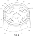
- the housing 110 includes an end wall 111 and a side wall 112 surrounding the end wall 111.
- the side wall 112 and the end wall 111 together form a cylinder having a closed end and an opening 114 at the other end.
- a rolling groove 113 is formed on the side wall 112 of the housing 110 close to the opening 114, the rolling groove 113 is recessed toward the inside of the housing 110.
- a relatively smooth welding plane 1131 is formed on one side of the rolling groove 113 facing away from the electrode assembly 120.
- the electronic assembly 120 is sealed in the housing 110, and there is no specific limitation to the sealing method.
- the electrode assembly 120 is a component in the battery cell where electrochemical reactions occur.
- the housing 110 may include one or more electrode assemblies 120.
- the electrode assembly 120 is mainly formed by winding or stacking positive electrode sheets and negative electrode sheets, and normally a separator is disposed between the positive electrode sheet and the negative electrode sheet.
- the positive electrode sheet includes a positive electrode current collecting body and a positive electrode active substance layer.
- the positive electrode active substance layer is coated on the surface of the positive electrode current collecting body.
- the positive electrode current collecting body includes a positive electrode coating region and a positive electrode tab connected to the positive electrode coating region.
- the positive electrode coating region is coated with the positive electrode active substance layer, and the positive electrode tab is not coated with the positive electrode active substance layer.
- the material of the negative electrode current collecting body may be copper, and the negative electrode active substance layer may include a negative electrode active substance.
- the negative electrode active substance may be carbon, silicon, or the like.
- the material of the separator may be PP (polypropylene) or PE (polyethylene), etc.
- the battery cell may also be covered with an insulating film.
- the insulating film may be synthesized from PP, PE, PET (polyethylene terephthalate), PVC (Polyvinyl Chloride) or other polymer materials.
- the electrode assembly 120 When assembling the cylindrical battery cell 100, the electrode assembly 120 is disposed in the housing 110 first, and then the rolling groove 113 is formed on the side wall 112 of the housing 110 near the opening 114 to position the electrode assembly 120 in the axial direction; thereafter the current collector 130 is disposed so that one end of the current collector 130 is welded to the rolling groove 113, and the other end of the current collector 130 is welded to the negative electrode tab of the electrode assembly 120; finally, the sealing ring 150 and the end cap 160 are disposed at the opening 114. By performing pier-sealing on the housing 110 at the opening 114, the end cap 160 is sealed on the housing 110, thus completing the assembly process of the cylindrical battery cell 100.
- the electrode assembly 120 is sealed in the housing 110 and is located between the rolling groove 113 and the end wall 111 of the housing 110.
- the rolling groove 113 limits the movement of the electrode assembly 120 in the axial direction of the housing 110.
- a first tab 121 and a second tab are respectively disposed at both ends of the length direction of the electrode assembly 120, and the polarity of the first tab 121 is opposite to the polarity of the second tab, wherein the first tab 121 faces the opening 114 of the housing 110, and the first tab 121 is the negative electrode tab.
- the first tab 121 may also be a positive electrode tab.
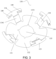
- the current collector 130 is disposed in the housing 110.
- the current collector 130 includes a housing connection portion 133, a tab connection portion 132 and a connection arm 134.
- One end of the connection arm 134 is connected to the housing connection portion 133
- the other end of the connection arm 134 is connected to the tab connection portion 132
- the housing connection portion 133 is disposed around the outer periphery of the tab connection portion 132
- the housing connection portion 133 is welded to the welding plane 1131 on the rolling groove 113.
- the tab connection portion 132 is electrically connected to the first tab 121, thereby realizing that the housing 110 and the first tab 121 have the same electrical properties.
- a positioning portion 140 is disposed on the housing connection portion 133.
- the positioning portion 140 is disposed to limit the displacement of the housing connection portion 133 in the radial direction of the housing 110.
- the specific structural form of the positioning portion 140 as long as it is possible to limit the displacement of the housing connection portion 133 in the radial direction of the housing 110.
- the positioning portion 140 may limit the displacement of the housing connection portion 133 in the radial direction by any position-limiting methods such as abutting against the inner wall of the housing 110 or abutting against the inner side wall 1132 of the rolling groove 113.
- the positioning portion 140 is not disposed on the housing connection portion 133 and the positioning portion 140 is disposed on the connection arm 134.
- Such configuration may also achieve the effect of limiting the displacement of the housing connection portion 133 in the radial direction of the housing 110.
- the positioning portion 140 may also be disposed on both the housing connection portion 133 and the connection arm 134. With such configuration, the above-mentioned advantageous effects may also be achieved.
- the housing connection portion 133 needs to move close to the rolling groove 113 under the action of tooling pressure until the housing connection portion 133 is completely pressed against the welding plane 1131 of the rolling groove 113. During this process, the housing connection portion 133 will move close to the rolling groove 113 along the radial direction of the electrode assembly 120, and therefore a certain displacement will be generated in the radial direction.
- the housing connection portion 133 Since the housing connection portion 133 is in a free state in the radial direction during the pressing process, there will be a deviation in the resulting displacement in the radial direction, which affects the welding area of the housing connection portion 133 on the welding plane 1131 of the rolling groove 113, and in turn affects the conductivity stability of the housing 110 and current collector 130.
- a position-limiting function may be achieved in the radial direction in the pressing process of the housing connection portion 133, such that the magnitude of displacement in the radial direction may be accurately controlled, and accurate positioning and connection of the housing connection portion 133 in the radial direction of the rolling groove 113 may be realized.
- the stability of the welding area between the housing connection portion 133 and the rolling groove 113 is improved, so that the stability of the overall current-carrying capacity of the cylindrical battery cell 100 is enhanced.
- the configuration and positioning accuracy between the housing 110 and the current collector 130 is enhanced, the stability of the assembly quality of the cylindrical battery cell 100 is improved, thereby increasing the stability of the performance of the cylindrical battery cell 100.
- the current collector 130 further includes a plate body 131.
- the plate body 131 is located in the middle of the current collector 130, and the connection arm 134 is located at the outer periphery of the current collector 130.
- the connection arm 134 is distributed radially along the center of the current collector 130.
- One end of the connection arm 134 is connected to the plate body 131, and the other end of the connection arm 134 is connected to the housing connection portion 133.
- the housing connection portion 133 extends along the circumferential direction of the housing 110 to form an arc-shaped plane.
- a positioning portion 140 extending toward the electrode assembly 120 side is formed on the side wall of the arc-shaped plane close to the axis of the current collector 130, and the positioning portion 140 abuts against the inner side wall 1132 of the rolling groove 113.
- the positioning portion 140 is relatively close to the housing connection portion 133, resulting in a better positioning effect.
- the positioning portion 140 may be integrally formed with the housing connection portion 133, or may be formed separately and then connected by welding as long as the requirements for connection strength of the positioning portion 140 can be met.
- the positioning portion 140 may have a variety of structures, such as a panel structure, a cylindrical structure, an arc plate structure, or any other structure that can abut against the inner side wall 1132 of the rolling groove 113.
- the positioning portion 140 is a panel structure. With such configuration, during the process of pressing the housing connection portion 133, there is a linear contact between the panel structure and the inner side wall 1132 of the rolling groove 113, which reduces the sliding resistance between the positioning portion 140 and the inner side wall 1132 of the rolling groove 113, thereby reducing the probability that the positioning portion 140 or the inner side wall 1132 of the rolling groove 113 is damaged during the pressing process.
- the positioning portion 140 of the housing 110 may also be an arc plate structure corresponding to the curvature of the inner side wall 1132 of the rolling groove 113.
- Such structure makes it possible to form a large contact area at the inner side wall 1132 of the rolling groove 113, thereby obtaining a higher resistance strength.
- the forming process of the arc plate structure is complicated and the manufacturing cost is high.
- the sliding resistance between the positioning portion 140 and the inner side wall 1132 of the rolling groove 113 is large, and the positioning portion 140 or the inner side wall 1132 of the rolling groove 113 will be very likely to be damaged during the pressing process.
- the accuracy for the positioning portion 140 of the housing 110 to perform positioning in the radial direction of the rolling groove 113 might be reduced.
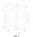
- the positioning portion 140 is disposed on the housing connection portion 133, and the at least two positioning portions 140 are respectively located on both sides of the connection arm 134.
- the positioning portions 140 may be disposed close to both sides of the connection arm 134, or may be disposed at a certain distance from both sides of the connection arm 134.
- the number of positioning portion 140 on both sides of the connection arm 134 and the number of positioning portion 140 on both sides of the connection arm 134 may be the same or different.
- positioning support points may be formed on both sides of the housing connection portion 133, thereby achieving better positioning strength and positioning accuracy during the positioning process.
- two positioning portions 140 are disposed on the housing connection portion 133, the two positioning portions 140 are symmetrically disposed on both sides of the connection arm 134, and the two positioning portions 140 are respectively located on both ends of the housing connection portion 133 in the circumferential extension direction.
- symmetrical support strength may be obtained at both ends of the housing connection portion 133, so that the force may be more evenly applied to the housing connection portion 133, thereby reducing the stress on the housing connection portion 133 and improving the stability of the welding between the housing connection portion 133 and the rolling groove 113.
- the size of the positioning portion 140 is relatively independent from the extension size of the housing connection portion 133 in the circumferential direction.
- the circumferential extension size of the housing connection portion 133 needs to be increased to meet the requirement of current-carrying capability, there is no need to increase the size of the positioning portion 140, while the small size of the positioning portion 140 may facilitate the sliding of the positioning portion 140 relative to the inner side wall 1132 of the rolling groove 113, thereby reducing the probability that the positioning portion 140 or the inner side wall 1132 of the rolling groove 113 is damaged during the pressing process.
- the positioning portion 140 is formed by the connection arm 134 extending along the height direction of the housing 110 toward the electrode assembly 120 side, and the positioning portion 140 abuts against the inner side wall 1132 of the rolling groove 113.
- the positioning portion 140 and the connection arm 134 may be integrally formed and connected, or they may be formed separately and then connected by welding as long as the requirements for connection strength of the positioning portion 140 can be met.
- Such configuration may also serve a positioning effect on the housing connection portion 133 in the radial direction, and the positioning portion 140 will not easily interfere with the sealing ring 150 above the rolling groove 113, and is also able to facilitate the subsequent sealing configuration of components.
- the positioning effect is not as good as that in which the positioning portion 140 is directly disposed on the housing connection portion 133.
- An obtuse angle a is formed between the positioning portion 140 and the housing connection portion 133, and the rolling groove 113 is disposed in the region where the obtuse angle ⁇ is disposed.
- the angle between the positioning portion 140 and the housing connection portion 133 is 90 degrees, which serves the function of welding positioning.
- the rolling groove 113 exerts a radial force on the positioning portion 140 toward the axis of the electrode assembly 120, so that the angle between the positioning portion 140 and housing connection portions 133 increases, thus forming an obtuse angle ⁇ .
- the setting of the obtuse angle ⁇ between the housing connection portion 133 and the positioning portion 140 increases the vertical distance between the lower end of the positioning portion 140 and the electrode assembly 120, thus reducing the probability that the positioning portion 140 is inserted into the electrode assembly 120 and damages the electrode sheet when the housing 110 is pier-sealed.
- a stress buffering structure is disposed on the connection arm 134 to reduce the stress transmitted to the tab connection portion 132 and the plate body 131 during pier-sealing.
- a large compressive stress will be generated on the housing connection portion 133.
- the compressive stress will be transmitted to the tab connection portion 132 through the connection arm 134, and the stability of welding of the tab connection portion 132 will be affected.
- a stress buffering structure By disposing a stress buffering structure on the connection arm 134, a part of the stress transmitted by the housing connection portion 133 may be alleviated.
- the stress transmitted to the tab connection portion 132 may be reduced, thereby improving the stability of welding connection of the tab connection portion 132.
- the stress buffering structure may be any structure that can serve a stress buffering function, such as a bending structure or a flexible material for connection, the disclosure is not limited thereto.
- connection arm 134 is integrally connected to the housing connection portion 133 and the plate body 131.
- the connection arm 134 includes a plurality of bending portions 1341, and the bending portion 1341 is deformed when being pressed.
- the bending angle of the bending portion 1341 may be any degrees, and the shape of the bending portion 1341 may be a combination of multiple shapes or a repeated arrangement of a single shape.
- the bending portion 1341 may be an arrangement of multiple arc-shaped protrusions, or may be a wavy structure composed of multiple undulations, etc.
- connection arm 134 is connected to the plate body 131 at a lower level, the other end of the connection arm 134 is connected to the housing connection portion 133 at a higher level.
- a plurality of bending portions 1341 are disposed at the connection between the connection arm 134 and the plate body 131. The plurality of bending portions 1341 are connected in sequence to form a protrusion in the direction facing away from the electrode assembly 120.
- connection arm 134 not only makes it possible to achieve the function of stress buffering, reduce the transmission of stress on the connection arm 134, improve the stability of welding of the tab connection portion 132, but also makes it possible to form a smooth transition connection between the connection arm 134 and the plate body 131, reduce the stress concentration at this position and improve the connection strength between the connection arm 134 and the plate body 131.
- connection arm 134 and the housing connection portion 133 are independent parts, and the connection arm 134 is made of a flexible material.
- the flexible material may be any flexible materials that meet the requirements of electrical conductivity and connection strength such as a conductor formed by stacking multiple layers of metal foil.
- One end of the connection arm 134 is connected to the housing connection portion 133, and the other end of the connection arm 134 is connected to the plate body 131.
- the connection method between the connection arm 134, the housing connection portion 133 and the plate body 131 may be welding or riveting that meets the requirements of connection strength and conductivity performance.
- connection arm 134 By setting the connection arm 134 to a flexible material, since the flexible material is able to buffer the stress transmitted on the connection arm 134 through the deformation of the flexible material, it is possible to alleviate the stress transmitted from the housing connection portion 133 to the tab connection portion 132 through the connection arm 134, so that the stress deformation generated on the tab connection portion 132 may be decreased, and the stability of welding of the tab connection portion 132 may be enhanced. In the meantime, the stress applied on the plate body 131 may be decreased and the probability of the plate body 131 being torn and damaged due to large stress deformation may be reduced.
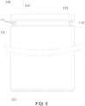
- a sealing ring 150 is disposed on one side of the rolling groove 113 away from the electrode assembly 120, and an avoidance structure 151 is disposed on an end surface of the sealing ring 150 facing the housing connection portion 133 to avoid the welding mark 1331 formed by the housing connection portion 133 on the rolling groove 113.
- the avoidance structure 151 may be an annular groove structure or a plurality of local notch structures, and the size and number of the notches match the number and size of the housing connection portion 133.
- the avoidance structure 151 is an annular groove structure.
- an avoidance space may be formed between the sealing ring 150 and the rolling groove 113, so that the housing connection portion 133 is accommodated in the avoidance space.
- the pressing force generated by the sealing ring 150 on the housing connection portion 133 may be reduced, and therefore it is possible to reduce the probability that the welding mark 1331 on the housing connection portion 133 is damaged and failed, thus enhancing the stability of the welding connection between the housing connection portion 133 and the rolling groove 113.
- the plate body 131 is disposed at the center of the current collector 130, the tab connection portion 132 is disposed along the circumferential direction of the plate body 131, and the connection arm 134 is disposed between the adjacent tab connection portions 132.
- One end of the connection arm 134 in the length direction is connected to the plate body 131, and the other end of the connection arm 134 in the length direction is connected to the housing connection portion 133.
- Hollow regions 136 are disposed on both sides of the connection arm 134 in the width direction, and the connection arm 134 is cantilevered along the length direction between two adjacent tab connection portions 132.
- the configuration of the hollow region 136 makes the connection arm 134 and the adjacent tab connection portions 132 to be partially disconnected. Such configuration may further reduce the stress transmitted from the connection arm 134 to the tab connection portion 132, thereby reducing the stress deformation on the tab connection portion 132 and improving the stability of the welding connection of the tab connection portion 132. It should be noted that there is no specific limitation to the specific structural form of the hollow region 136.
- the hollow region 136 may have any structural shape such as a long strip structure, a square structure, etc.; there is no limitation to the area size of the hollow region 136 as long as the requirement of current-guiding for the connection arm 134 and the requirement of welding strength for the tab connection portion 132 can be met.
- the hollow region 136 is a wedge-shaped structure, and one end of the wedge-shaped structure with a large opening faces the housing connection portion 133.
- Such configuration not only makes it possible to ensure that when the housing connection portion 133 is pressed, the connection arm 134 will not easily come into contact with the tab connection portions 132 on adjacent sides when deformed to avoid stress transmission, but also ensure the connection strength between the connection arm 134 and the plate body 131.
- an exhaust hole 135 is disposed in the center of the current collector 130, and a cut 1351 is disposed on the side wall along the circumference of the exhaust hole 135.
- the cut 1351 may be strip-shaped, triangular, or pointed.
- the current collector 130 forms a fragile region at the cut 1351.
- the current collector 130 will form a tear at the cut 1351 under the action of high-temperature pressure, and the current collector 130 will be quickly torn apart, so that the high-pressure gas in the electrode assembly 120 can be quickly discharged to quickly relieve pressure and reduce the probability of explosion of the cylindrical battery cell 100 in the lateral direction.
- the present disclosure further provides a battery assembly, which includes the cylindrical battery cells 100 described in any one of the examples provided above, and a plurality of cylindrical battery cells 100 are connected in series or in parallel. Or, a plurality of cylindrical battery cells 100 are connected in series and in parallel as a combination to form the battery modules and battery packs.
- the present disclosure further provides an electrical device, which includes a working portion and the battery assembly described above, and the working portion is electrically connected to the battery assembly to obtain electrical energy for support.
- the working portion may be a unit component that is able to obtain the electric energy of the battery assembly and perform corresponding work, such as a blade rotating unit of a fan, a dust collection working unit of a vacuum cleaner, a wheel driving unit in an electric vehicle, etc.
- the electrical device may be vehicles, cell phones, portable devices, laptops, ships, spacecraft, electric toys and power tools, etc.
- Vehicles may be fuel vehicles, gas vehicles or new energy vehicles, and new energy vehicles may be pure electric vehicles, hybrid vehicles or extended-range vehicles, etc.
- spacecraft include aircraft, rockets, space shuttles, spaceships, etc.
- electric toys include fixed type or mobile electric toys, such as game consoles, electric toy cars, electric toy ships and electric toy airplanes, etc.
- electric tools include metal cutting electric tools, grinding electric tools, assembly electric tools and railway electric tools, for example, electric drills, electric grinders, electric wrenches, electric screwdrivers, electric hammers, impact drills, concrete vibrators, planers and more.
- the embodiments of this disclosure impose no special limitation to the above-mentioned electrical device.
- the positioning portion 140 is disposed on the housing connection portion 133 and/or the connection arm 134, which serves a position-limiting function in the radial direction during the pressing process of the housing connection portion 133, thereby accurately controlling the displacement in the radial direction, and realizing the accurate positioning and connection of the housing connection portion 133 in the radial direction of the rolling groove 113.
- the stability of the welding connection area between the housing connection portion 133 and the rolling groove 113 is enhanced, so that the stability of the overall current-carrying capacity of the cylindrical battery cell 100 is increased.
- the positioning portion 140 is disposed as a panel structure, so that during the pressing process of the housing connection portion 133, there is a linear contact between the panel structure and the inner side wall 1132 of the rolling groove 113, which reduces the sliding resistance between the positioning portion 140 and the inner side wall 1132 of the rolling groove 113. In this way, it is possible to reduce the probability that the positioning portion 140 or the inner side wall 1132 of the rolling groove 113 is damaged during the pressing process, thus improving the accuracy for the positioning portion 140 of the housing 110 to position the rolling groove 113 in the radial direction. Therefore, the disclosure effectively overcomes some practical problems in the related art and has high values of utilization and significance of use.
Landscapes
- Chemical & Material Sciences (AREA)
- Chemical Kinetics & Catalysis (AREA)
- Electrochemistry (AREA)
- General Chemical & Material Sciences (AREA)
- Engineering & Computer Science (AREA)
- Manufacturing & Machinery (AREA)
- Connection Of Batteries Or Terminals (AREA)
- Sealing Battery Cases Or Jackets (AREA)
- Gas Exhaust Devices For Batteries (AREA)
Applications Claiming Priority (1)
| Application Number | Priority Date | Filing Date | Title |
|---|---|---|---|
| CN202321793900.7U CN220628150U (zh) | 2023-07-07 | 2023-07-07 | 一种圆柱电芯、电池组及电子设备 |
Publications (1)
| Publication Number | Publication Date |
|---|---|
| EP4489154A1 true EP4489154A1 (de) | 2025-01-08 |
Family
ID=89222647
Family Applications (1)
| Application Number | Title | Priority Date | Filing Date |
|---|---|---|---|
| EP23216384.0A Pending EP4489154A1 (de) | 2023-07-07 | 2023-12-13 | Zylindrische batteriezelle, batterieanordnung und elektrische vorrichtung |
Country Status (4)
| Country | Link |
|---|---|
| US (1) | US20250015450A1 (de) |
| EP (1) | EP4489154A1 (de) |
| JP (1) | JP7743487B2 (de) |
| CN (1) | CN220628150U (de) |
Families Citing this family (3)
| Publication number | Priority date | Publication date | Assignee | Title |
|---|---|---|---|---|
| CN121889934A (zh) * | 2023-09-29 | 2026-04-17 | 松下知识产权经营株式会社 | 圆筒形二次电池 |
| CN222940150U (zh) * | 2024-08-15 | 2025-06-03 | 株式会社Aesc日本 | 二次电池、电池组及电子装置 |
| CN223333961U (zh) * | 2024-09-18 | 2025-09-12 | 株式会社Aesc日本 | 二次电池、电池组及电子装置 |
Citations (2)
| Publication number | Priority date | Publication date | Assignee | Title |
|---|---|---|---|---|
| WO2022191514A1 (ko) * | 2021-03-08 | 2022-09-15 | 주식회사 엘지에너지솔루션 | 원통형 이차전지, 배터리팩 및 이동수단 |
| KR20230057991A (ko) * | 2021-10-22 | 2023-05-02 | 주식회사 엘지에너지솔루션 | 원통형 배터리, 그리고 이를 포함하는 배터리 팩 및 자동차 |
Family Cites Families (1)
| Publication number | Priority date | Publication date | Assignee | Title |
|---|---|---|---|---|
| KR20230068246A (ko) * | 2021-11-10 | 2023-05-17 | 주식회사 엘지에너지솔루션 | 원통형 이차전지에 전해액을 주입하는 주액기 입구 구조물 및 전해액 주입 방법 |
-
2023
- 2023-07-07 CN CN202321793900.7U patent/CN220628150U/zh active Active
- 2023-12-06 US US18/531,658 patent/US20250015450A1/en active Pending
- 2023-12-11 JP JP2023208524A patent/JP7743487B2/ja active Active
- 2023-12-13 EP EP23216384.0A patent/EP4489154A1/de active Pending
Patent Citations (2)
| Publication number | Priority date | Publication date | Assignee | Title |
|---|---|---|---|---|
| WO2022191514A1 (ko) * | 2021-03-08 | 2022-09-15 | 주식회사 엘지에너지솔루션 | 원통형 이차전지, 배터리팩 및 이동수단 |
| KR20230057991A (ko) * | 2021-10-22 | 2023-05-02 | 주식회사 엘지에너지솔루션 | 원통형 배터리, 그리고 이를 포함하는 배터리 팩 및 자동차 |
Also Published As
| Publication number | Publication date |
|---|---|
| CN220628150U (zh) | 2024-03-19 |
| JP2025010464A (ja) | 2025-01-21 |
| US20250015450A1 (en) | 2025-01-09 |
| JP7743487B2 (ja) | 2025-09-24 |
Similar Documents
| Publication | Publication Date | Title |
|---|---|---|
| US20240128604A1 (en) | Battery cell, battery, electrical device, and manufacturing method and device for battery cell | |
| EP4489154A1 (de) | Zylindrische batteriezelle, batterieanordnung und elektrische vorrichtung | |
| KR20220146627A (ko) | 배터리 셀, 배터리 및 전기 설비 | |
| EP4148896A1 (de) | Batteriezelle, batterie, stromverbrauchende vorrichtung sowie verfahren und vorrichtung zur herstellung einer batteriezelle | |
| US20240055646A1 (en) | Wound electrode assembly, battery cell, battery, and electrical device | |
| US20250096437A1 (en) | Battery cell, battery, and electric device | |
| EP4068490A1 (de) | Batteriezelle, batterie, elektrische vorrichtung, herstellungsverfahren und vorrichtung für eine batteriezelle | |
| US20250158242A1 (en) | Secondary battery, battery assembly and electronic apparatus | |
| US20250329884A1 (en) | Battery cell, battery, and electrical device | |
| US20240055705A1 (en) | Battery cell, battery, power consuming apparatus, and method and apparatus for manufacturing battery cell | |
| JP7652920B2 (ja) | タブ溶接構造、電池セル、電力消費機器、タブの溶接方法及びタブの溶接機器 | |
| US20250192398A1 (en) | Electrode assembly, battery cell, battery, and electrical device | |
| US20250149752A1 (en) | Secondary battery, battery assembly and electronic device | |
| US20250038318A1 (en) | Cylindrical battery cell, battery assembly and electronic device | |
| CN220553562U (zh) | 圆柱电芯、电池组及电子设备 | |
| US20240313310A1 (en) | Battery cell, method and device for manufacture same, battery, and power consuming device | |
| US20250038368A1 (en) | Cylindrical battery cell and battery pack | |
| EP4697484A1 (de) | Sekundärbatterie, batteriepack und elektronische vorrichtung | |
| US20260051626A1 (en) | Secondary battery, battery cell, and electronic device | |
| CN221239714U (zh) | 二次电池、电池组及电子设备 | |
| US20260018751A1 (en) | Current collector, secondary battery and electronic device | |
| US20260112654A1 (en) | Secondary battery, battery pack, and electronic device | |
| EP4683101A1 (de) | Verbindungselement, batteriezelle, batterie und elektrische vorrichtung | |
| US20260051624A1 (en) | Secondary battery, battery pack and electronic device | |
| US20260024888A1 (en) | Adapter sheet, secondary battery, battery assembly and electronic device |
Legal Events
| Date | Code | Title | Description |
|---|---|---|---|
| PUAI | Public reference made under article 153(3) epc to a published international application that has entered the european phase |
Free format text: ORIGINAL CODE: 0009012 |
|
| STAA | Information on the status of an ep patent application or granted ep patent |
Free format text: STATUS: REQUEST FOR EXAMINATION WAS MADE |
|
| 17P | Request for examination filed |
Effective date: 20231213 |
|
| AK | Designated contracting states |
Kind code of ref document: A1 Designated state(s): AL AT BE BG CH CY CZ DE DK EE ES FI FR GB GR HR HU IE IS IT LI LT LU LV MC ME MK MT NL NO PL PT RO RS SE SI SK SM TR |