EP4488998A2 - Audiodekorrelator, verarbeitungssystem und verfahren zum dekorrelieren eines audiosignals - Google Patents
Audiodekorrelator, verarbeitungssystem und verfahren zum dekorrelieren eines audiosignals Download PDFInfo
- Publication number
- EP4488998A2 EP4488998A2 EP24214169.5A EP24214169A EP4488998A2 EP 4488998 A2 EP4488998 A2 EP 4488998A2 EP 24214169 A EP24214169 A EP 24214169A EP 4488998 A2 EP4488998 A2 EP 4488998A2
- Authority
- EP
- European Patent Office
- Prior art keywords
- decorrelator
- frequency representation
- audio signal
- signal
- delay
- Prior art date
- Legal status (The legal status is an assumption and is not a legal conclusion. Google has not performed a legal analysis and makes no representation as to the accuracy of the status listed.)
- Granted
Links
Images


Classifications
-
- G—PHYSICS
- G10—MUSICAL INSTRUMENTS; ACOUSTICS
- G10L—SPEECH ANALYSIS TECHNIQUES OR SPEECH SYNTHESIS; SPEECH RECOGNITION; SPEECH OR VOICE PROCESSING TECHNIQUES; SPEECH OR AUDIO CODING OR DECODING
- G10L19/00—Speech or audio signals analysis-synthesis techniques for redundancy reduction, e.g. in vocoders; Coding or decoding of speech or audio signals, using source filter models or psychoacoustic analysis
- G10L19/008—Multichannel audio signal coding or decoding using interchannel correlation to reduce redundancy, e.g. joint-stereo, intensity-coding or matrixing
-
- H—ELECTRICITY
- H04—ELECTRIC COMMUNICATION TECHNIQUE
- H04S—STEREOPHONIC SYSTEMS
- H04S7/00—Indicating arrangements; Control arrangements, e.g. balance control
- H04S7/30—Control circuits for electronic adaptation of the sound field
- H04S7/301—Automatic calibration of stereophonic sound system, e.g. with test microphone
-
- G—PHYSICS
- G10—MUSICAL INSTRUMENTS; ACOUSTICS
- G10L—SPEECH ANALYSIS TECHNIQUES OR SPEECH SYNTHESIS; SPEECH RECOGNITION; SPEECH OR VOICE PROCESSING TECHNIQUES; SPEECH OR AUDIO CODING OR DECODING
- G10L19/00—Speech or audio signals analysis-synthesis techniques for redundancy reduction, e.g. in vocoders; Coding or decoding of speech or audio signals, using source filter models or psychoacoustic analysis
- G10L19/02—Speech or audio signals analysis-synthesis techniques for redundancy reduction, e.g. in vocoders; Coding or decoding of speech or audio signals, using source filter models or psychoacoustic analysis using spectral analysis, e.g. transform vocoders or subband vocoders
-
- G—PHYSICS
- G10—MUSICAL INSTRUMENTS; ACOUSTICS
- G10L—SPEECH ANALYSIS TECHNIQUES OR SPEECH SYNTHESIS; SPEECH RECOGNITION; SPEECH OR VOICE PROCESSING TECHNIQUES; SPEECH OR AUDIO CODING OR DECODING
- G10L19/00—Speech or audio signals analysis-synthesis techniques for redundancy reduction, e.g. in vocoders; Coding or decoding of speech or audio signals, using source filter models or psychoacoustic analysis
- G10L19/04—Speech or audio signals analysis-synthesis techniques for redundancy reduction, e.g. in vocoders; Coding or decoding of speech or audio signals, using source filter models or psychoacoustic analysis using predictive techniques
- G10L19/26—Pre-filtering or post-filtering
-
- G—PHYSICS
- G10—MUSICAL INSTRUMENTS; ACOUSTICS
- G10L—SPEECH ANALYSIS TECHNIQUES OR SPEECH SYNTHESIS; SPEECH RECOGNITION; SPEECH OR VOICE PROCESSING TECHNIQUES; SPEECH OR AUDIO CODING OR DECODING
- G10L21/00—Speech or voice signal processing techniques to produce another audible or non-audible signal, e.g. visual or tactile, in order to modify its quality or its intelligibility
- G10L21/02—Speech enhancement, e.g. noise reduction or echo cancellation
- G10L21/0316—Speech enhancement, e.g. noise reduction or echo cancellation by changing the amplitude
-
- H—ELECTRICITY
- H04—ELECTRIC COMMUNICATION TECHNIQUE
- H04S—STEREOPHONIC SYSTEMS
- H04S1/00—Two-channel systems
- H04S1/007—Two-channel systems in which the audio signals are in digital form
-
- H—ELECTRICITY
- H04—ELECTRIC COMMUNICATION TECHNIQUE
- H04S—STEREOPHONIC SYSTEMS
- H04S2400/00—Details of stereophonic systems covered by H04S but not provided for in its groups
- H04S2400/01—Multi-channel, i.e. more than two input channels, sound reproduction with two speakers wherein the multi-channel information is substantially preserved
Definitions
- the present invention relates to a decorrelator for an audio signal, to a processing system having such a decorrelator, to a decorrelation method and to a computer program product.
- the present invention in particular relates to an audio signal decorrelator.
- decorrelators are an important building block for parametric spatial audio coding.
- Known solutions relate to decorrelators known from parametric spatial audio coding like parametric stereo or MPEG surround.
- Decorrelators as described in [1] or [2] use computationally costly time domain reverberation (reverb) filters with a long impulse response.
- Decorrelators such as described in [3] or [4] require the use of a Quadrature Mirror Filterbank (QMF) with considerable processing delay and computationally expensive Lattice filters.
- QMF Quadrature Mirror Filterbank
- a finding of the present invention is that dividing a frequency representation in a plurality of parts and for processing, i.e., delaying each of the parts with a separate delay unit, allows for a low processing delay, as the computational the different parts may be performed in parallel. As the same time, such frequency domain operations require a low computational complexity.
- a decorrelator comprises a plurality of delay units, wherein each delay unit is configured for receiving a part of a frequency representation being based on an audio signal, wherein each delay unit is configured for delaying the received part to provide a delayed part.
- the decorrelator comprises an envelope shaper configured for receiving an combining signals being based on the delayed parts of the frequency representation, for receiving the frequency representation of the audio signal, for adjusting an energy of the delayed parts in respect of the frequency representation of the audio signal and for providing a combined shape frequency representation.
- different parts of the frequency representation comprise a same or a different number of frequency bins. Wherein a same number of frequency bins may allow for a same processing time, a different number of frequency bins may allow for an adaptation towards application requirements.
- the decorrelator comprises a phase shifter configured for phase shifting the frequency representation of the audio signal, or for phase shifting the audio signal in a time domain to obtain a phase shifted audio signal.
- Phase shifting may allow for a perceived reverberation and therefore for a high audio quality.
- the phase shifter is configured for a phase shifting the frequency representation of the audio signal and comprises a plurality of Allpass filters, wherein each Allpass filter is configured for phase shifting an associated part of the frequency representation of the audio signal. That is, the Allpass filter may be associated and adapted towards the respective part of the audio signal which may allow for a high overall audio quality.
- an Allpass filter of the plurality of Allpass filters comprises a set of Allpass filter structures being serially connected to each other, i.e., using Schroeder IIR filters.
- the Allpass filter structures are adapted for providing different time delays.
- the Allpass filter structures comprise a nested Allpass filter structure.
- a number of Allpass filter structures and/or a circuitry of the Allpass filter structure is equivalent or different between different Allpass filters. This allows for a high flexibility of the decorrelator.
- the different time delays are based on a prime number multiple of a local sampling rate used for obtaining the frequency representation of the audio signal. This allows for a high perceived audio quality.
- the set of Allpass filter structures comprises a number of four Allpass filter structures and are adapted for providing a delay of 1, 2, 3 and 5 time units.
- Reasonable other time units may be, for example, 32 or 64 samples or other values.
- the time units are preferably short enough to allow for sufficient time resolution in the subsequent time/frequency envelope shaping.
- a delay of 1, 3, 5 and 7 is provided by the four Allpass filter structures. This allows to avoid overlaps in the time domain.
- a gain factor of the Allpass filter is adapted to a value with a magnitude, i.e., positive or negative values, of 0.7 within a tolerance range.
- the tolerance range is, for example, 20%, 10% or 5%.
- the phase shifter is configured for phase shifting the audio signal in a time domain, wherein the phase shifter comprises a set of Allpass filter structures being serially connected to each other, wherein the Allpass filter structures are adapted for providing different time delays.
- the Allpass filter structures comprise a nested Allpass filter structure.
- the different Allpass time delays are based on a prime number multiple of a reciprocal of a sampling rate used for obtaining the frequency representation of the audio signal.
- a corresponding advantage may also be obtained in the time domain.
- different time delays may be based on a prime number being obtained by multiplying each of a set of minimal prime numbers, e.g., 1, 2, 3 and 5 as one example set or 1, 3, 5 and 7 as another example set with a downsampling factor used for generating the parts of the frequency representation of the audio signal to obtain an intermediate result and for using a next prime number with respect to the intermediate result.
- a closest distance may be understood, e.g., to obtain the next larger or next smaller prime-value.
- the values 131, 257, 383 and 641 may be obtained for the first set and 131, 383, 641 and 907 may be obtained for the second example set.
- one time unit may be 1 sample.
- the sample may relate to a sampling frequency being, e.g., 48kHz. In other embodiments, sampling frequency can also be 44.1 kHz or 32kHz or other values.
- the decorrelator comprises a first conversion unit for obtaining the frequency representation of the audio signal from the audio signal for the envelope shaper and comprising a second conversion unit for obtaining a frequency representation from the reverberated audio signal, wherein the parts of the frequency representation form parts of the frequency representation from the reverberated audio signal.
- the decorrelator is adapted for additionally implementing a same and predefined delay for a subset or all parts of the frequency representation. That is, a delay that is equal for the respective parts or delay lines may also be applied commonly in a common delay module which allows for simple delay units in the respective delay lines for an associated part.
- the delay units associated to a spectral part of the plurality of delay units are configured for delaying the associated part of the frequency representation differently when compared to delay units associated to other spectral parts. This allows for a high perceived quality by treating different frequency portions differently.
- the delay unit is configured for delaying parts of the frequency representation comprising lower frequencies with a higher time delay when compared to parts of the frequency representation comprising higher frequencies.
- a relationship between different time delays is linear, logarithmic and/or based on a rounding on subband samples. This allows for a high perceived quality.
- the decorrelator comprises a conversion unit for receiving an converting the audio signal or a reverberated version of the audio signal into the parts by performing a time-block-wise discrete Fourier transform, DFT, or short-time Fourier transform, STFT, wherein the conversion unit is configured for converting blocks having an overlap of 50% within a tolerance range.
- DFT time-block-wise discrete Fourier transform
- STFT short-time Fourier transform
- the envelope shaper is configured for operating in a subband domain and with a temporal resolution of less than 4 milliseconds.
- the decorrelator comprises a signal processing stage configured for receiving a signal based on the combined shaped frequency representation, e.g., as a mono signal, and for processing the mono signal at least to a stereo signal. This allows for an improved perception of a listener.
- the decorrelator comprises a signal processing stage configured for processing the combined shaped frequency representation at least to a stereo signal and for source extent modelling based on the at least stereo signal, e.g., in the frequency domain.
- a processing system comprises a decorrelator as described herein and a processing stage for transforming a mid/side decomposed signal to a left/right decomposed signal.
- the processing system may perform transient suppression to suppress echoes, e.g., pre-echoes and/or post-echoes caused by a transient.
- a transient handling may comprise muting the output of a decorrelator and, correspondingly, amplifying an output of a delay compensation unit providing for a portion of the left/right decomposed signal and being in parallel with the decorrelator and connected with the processing stage.
- a method comprises receiving a plurality of parts of a frequency representation being based on an audio signal, delaying each of the received parts to provide a plurality of delayed parts and receiving and combining signals being based on the delayed parts of the frequency representation.
- the method comprises receiving the frequency representation of the audio signal and adjusting an energy of the delayed parts in respect of the frequency representation of the audio signal.
- a combined shaped frequency representation is provided.
- a computer program or computer program product or a non-transitory storage medium having stored therein instructions to carry out respective instructions is provided for executing such a method, when running on a computer.
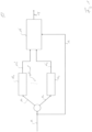
- Fig. 1 shows a schematic block diagram of a decorrelator 10 according to an embodiment.
- Decorrelator 10 comprises a number of at least two delay units 12 1 to 12 n with n > 1.
- Fig. 1 illustrates a number of two delay units 12, the number is preferably higher, e.g., 4, 8, 16 or other values to be obtained with a power of 2, wherein embodiments are not limited to such numbers. That is, embodiments may also comprise a number of 3, 5, 7 or 9 delay units 12.
- Each delay unit is configured for receiving an associated part 14 1 to 14 n of a frequency representation 14 being based on an audio signal.
- Each delay unit 12 1 to 12 n is configured for delaying the received part 14 1 to 14 n so as to provide a delayed part 14' 1 to 14' n , i.e., for having a delay in the time domain.
- the decorrelator 10 further comprises an envelope shaper 16 configured for receiving signals being based on the delay parts 14' 1 to 14' n . Such signals may be the delayed parts 14' 1 to 14' n themselves or processed variants thereof.
- the envelope shaper 16 is configured for combining the received signals.
- the envelope shaper is configured for receiving the frequency representation 14 of the audio signal.
- the envelope shaper 16 is configured for adjusting an energy of the delayed parts 14' 1 to 14' n in respect of the frequency representation 14 of the audio signal.
- the envelope shaper 16 is configured for providing a combined shaped frequency representation 18. In the combined shaped frequency representation 18, the respective parts 14 1 to 14 n , signals resulting thereof respectively, may be decorrelated with regard to one another and/or with regard to the frequency representation 14.
- the envelope shaper 16 may receive the respective information by receiving the possibly non-delayed or commonly treated parts 14 1 to 14 n .
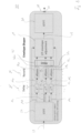
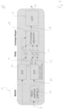
- Fig. 2 shows a schematic block diagram of a decorrelator 20 according to an embodiment.
- the decorrelator 20 is configured for receiving an audio signal 22.
- the decorrelator 20 may comprise a conversion unit 24 configured for generating the frequency representation 14 shown in Fig. 1 .
- the conversion unit 24 may provide for parts 14 1 to 14 16 being obtained by an example STFT.
- the frequency representation may comprise a number of 129 frequency bins in total. Alternatively, 128 bins may be used.
- two types of Digital Fourier Transforms (DFT) may be used, a so-called "evenly stacked" and an "oddly stacked".
- DFT Digital Fourier Transforms
- the evenly stacked version may be considered having, in the example provided, 129 bands (127 complex, one real and one imaginary).
- the oddly stacked may comprise 128 (complex) bands. Both transforms can be used in embodiments described herein.
- the parts 14 1 to 14 16 may comprise, partly or completely, a same or different number of bins.
- part 14 1 may comprise the first to the ninth bin, e.g., 9 bins.
- Part 14 2 comprises, for example, bins 10 to 19 and, thus, a number of ten bins.
- the adaptation or selection with regard to the number of bins may be based on the sampling frequency being in the illustrated example 48 kHz, the overlap that is, for example, 50% and/or a number of parts 14 1 to 14 16 to be generated.
- the parts 14 1 to 14 16 may comprise an equal or different number of frequency bins such that some or all parts 14 1 to 14 16 may also be generated so as to comprise a same number of frequency bins.
- the decorrelator 20 further comprises a delay section 25 having delay lines 12 1 to 12 16 , each delay line 12 1 to 12 16 being associated with one specific part 14 1 to 14 16 and configured for receiving said part, a processed version thereof respectively.
- the delay units 12 1 to 12 16 may be associated to a respective spectral part 14 1 to 14 16 .
- Such a delay unit 12 1 to 12 16 may be configured for delaying the associated part of the frequency representation 14 differently when compared to delay units associated to other spectral parts.
- a relationship between different time delays may be one of linear, logarithmic and/or based on a rounding on super band samples.
- the phase shifter 26 may be configured for phase shifting the frequency representation 14 of the audio signal, a processed, e.g., delayed, version thereof. The phase shifting may also be performed prior to converting the audio signal 22 into the frequency domain, a corresponding phase shifter may be configured for phase shifting the audio signal 22 in the time domain to obtain a phase shifted audio signal.
- the phase shifter may comprise a plurality of Allpass filters 28 1 to 28 16 . In the shown example, the Allpass filters 28 1 to 28 16 are configured to receive the delayed parts 14' 1 to 14' 16 .
- Allpass filter is to be understood that the frequency range to be passed corresponds to the frequency range of the respective part 14 1 to 14 16 . Wherein this may include examples where each of the Allpass filters 28 1 to 28 16 passes the complete frequency range provided in the frequency representation, the passband of different Allpass filters 28 1 to 28 16 may also differ from one another based on the different frequency bins contained in the respective parts 14 1 to 14 16 .
- Each of the Allpass filters 28 1 to 28 16 is configured for phase shifting an associated part of the frequency representation of the audio signal.
- a number of Allpass filter structures and/or a circuitry of the Allpass filter structure may be the same, i.e., equal or comparable, or may, alternatively, be different between different Allpass filters 28 1 to 28 16 .
- a time delay provided by the delay lines 12 1 to 12 16 may be same or may be different for different parts 14 1 to 14 16 .
- parts of the frequency representation comprising lower frequencies may be delayed with a higher time delay when compared to parts of the frequency representation comprising higher frequencies. From bin 1 to higher bins, a represented frequency may increase. As represented in the z-domain, the time delay may decrease with an increase of frequencies.
- Signals 32 1 to 32 16 may comprise a result of the delaying and the phase shifting, e.g., as an output of the Allpass filters 28 1 to 28 16 .
- the envelope shaper 16 may be configured for receiving signals 32 1 to 32 16 and an unfiltered and undelayed version thereof, i.e., the parts 14 1 to 14 16 , i.e., the frequency representation of the audio signal 22.
- the parts 14 1 to 14 16 may be understood as subbands.
- the envelope shaper 16 may be configured for operating in a subband domain. For example, a temporal resolution of the envelope shaper 16 may be at most or less than 4 milliseconds, e.g., 4 milliseconds, 3.5 milliseconds, 3 milliseconds or less.
- the decorrelator 20 may comprise another conversion unit 35 that may provide for an inverse operation when compared to the conversion unit 24.
- the conversion rate 34 may perform an inverse short term Fourier transform iSTFT.
- the combined shape frequency representation 18 may comprise information with regard to the frequency domain that is present in each of the bins such that the combined shaped frequency representation 18 may be treated correspondingly to the output of the conversion unit 24. That is, the conversion unit 34 may receive the processed versions of the parts 14 1 to 14 16 of the frequency representation 14 and for synthesizing a synthesized signal 36 from the processed versions 14' 1 to 14' 16 based on, e.g., an overlap-add procedure.
- the signal 36 may be provided, for example, at an interface 38 of the decorrelator 20.
- the envelope shaper 16 may be configured for shaping spectral bins in time and/or frequency. Shaping may be performed by the envelope shaper 26 for individual bins and/or for groups of bins, e.g., by implementing an interdependent or an at least groupwise common shaping processing.
- conversion unit 24 When referring again to conversion unit 24, same may be configured for receiving and converting the audio signal 22 or a reverberated version thereof into the parts 14 1 to 14 16 , wherein the number of 16 is an example only.
- the reverberated version of the audio signal 22 may be an input in case the phase shifter 26 operates in the time domain and may thus be arranged upstream of the conversion unit 24.
- the conversion unit 24 may perform a time-block-wise discrete Fourier transform, DFT, or a short-time Fourier transform, STFT.
- the conversion unit may be configured for converting blocks having an overlap of, e.g., 50% within a tolerance range.
- the tolerance range may be 0% as far as possible, at most 5%, at most 10%, at most 15% or more.
- the blocks may comprise a block length of, for example, 128 samples, 256 samples or 512 samples, wherein a value of 256 may be preferred.
- Fig. 3 shows a schematic block diagram of a decorrelation 30.
- the decorrelator 30 may additionally comprise a pre-delay 42, wherein the term pre-delay does not limit the delay to be implemented directly prior or subsequent to any specific block.
- the pre-delay 42 may be located at any stage prior to the envelope shaper 16, preferably and when operating in the frequency domain, after the conversion unit 24. That is, for example, a sequence between the Allpass filters of the reverberation or phase shifter 26 and the pre-delay 42 may be swapped when compared to the illustration in Fig. 3 .
- the pre-delay 42 or the delay block 42 may be configured to additionally implement a same and predefined delay for a subset or all of the parts 14 1 to 14 16 of the frequency representation. This may allow for implementing the same delay to each part 14 1 to 14 16 or a group thereof for combining the processing at this stage and to use delay lines 12 1 to 12 16 for adding a probably individual delay to differ from the common delay implemented in block 42.
- the pre-delay 42 is configured to allow for a constant pre-delay for all spectral bands.
- Fig. 4 shows a schematic block diagram of an Allpass filter 40 according to an embodiment that may be operated at least as a part of one of filters 28 1 to 28 16 of decorrelator 20 and/or 30.
- Allpass 40 may comprise a structure of a Schroeder IIR filter, for example, and may comprise a forward branch 46 in combination with a backward branch 48 in combination with a delay block 52 to provide for a respective output signal 54 being based on an input signal 44 of the Allpass filter 40.
- An Allpass filter 28 of decorrelator 20 and/or 30 may comprise one or more of such Allpass filters 40 being connected serially to one another. To provide for different time delays in different Allpass filters 28 1 to 28 16 , a different number of Allpass filter structures 14 may be serially connected.
- Fig. 4 shows an Allpass filter stage.
- Fig. 5 shows a schematic block diagram of an Allpass filter structure 50 being a nested Allpass filter structure.
- one or more Allpass filter structures 50 may form at least a part of an Allpass filter 28 1 to 28 16 of the decorrelator 20 and/or 30.
- two delay blocks 52, and 52 2 a different and especially higher number of delay blocks 52 may be present resulting possibly in an increased number of forward branches 46 and/or backward branches 48.
- gains g 1 /- g 1 and/or g 2 /-g 2 may be adopted.
- different Allpass filters 28 1 to 28 16 may be implemented so as to comprise a different time delay when compared to other Allpass filters.
- the different delays of different Allpass filter structures and/or circuitries of Allpass filter structures may be based on a prime number multiple of a local sampling rate, e.g., 48 kHz, used for obtaining the frequency representation 14 of the audio signal 22.
- a set of Allpass filter structures forming at least a part of an Allpass filter may comprise a number of four Allpass filter structures, e.g., Allpass filter structures 40.
- the different delay blocks therein may be adapted for providing a delay of 1, 2, 3 and 5.
- the number of four Allpass filter structures may provide a delay of 1, 3, 5 and 7 units in the z-domain.
- Those values may form a set of prime values, i.e., a number of 2, 3, 4, 5 or more prime values may be grouped.
- the time delays are based on a prime number multiple of a reciprocal of a sampling rate used for obtaining the frequency representation of the audio signal in an embodiment.
- the different time delays may be based on a prime number being obtained by multiplying each of a set of prime numbers as mentioned, for example, 1, 2, 3 and 5 or 1, 3, 5 and 7 with a down sampling factor used for generating the parts of the frequency representation of the audio signal to obtain an intermediate result.
- a next prime number with respect to the intermediate result may be used.
- each delay may relate to a multiplication with 1 sample at the sampling rate which is, for a sampling rate of 48 kHz approximately 20.8 ⁇ s.
- Other sets of prime numbers are possible without limitation.
- the gain factor g of the Allpass filter may be adapted to a value of 0.7 within a tolerance range of, for example, ⁇ 20%, ⁇ 10% or ⁇ 5%.
- the gain value may also have a negative value of, e.g., -0.7 within the mentioned tolerance range. That is, the gain factor may be adapted to a value with a magnitude of 0.7 within the tolerance range.
- Fig. 5 shows a simple nested Allpass filter stage.
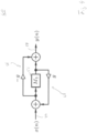
- Fig. 6 shows a schematic block diagram of a decorrelator 60 according to an embodiment.
- the decorrelator 60 comprises the phase shifter 26 configured to operate in the time domain.
- An Allpass filter structure 28' may be configured for using the respective next prime numbers when compared to the sets of prime numbers as described in connection with decorrelator 20 and/or 30.
- For ensuring a precise operation of decorrelator 60 same may comprise conversion units 24 1 and 24 2 . Whilst conversion unit 24, may provide for the frequency representation of the audio signal, conversion unit 24 2 may receive the reverberated or phase shifted audio signal 22' provided by the phase shifter 28'.
- the obtained parts 14" 1 to 14" 16 may be delayed by delay units 12 1 to 12 16 arriving at a comparable input for the envelope shaper 16 when compared to the decorrelator 20 and/or 30 whilst allowing for a time-domain based reverberation. That is, the parts of the frequency representation may form parts of the frequency representation from the reverberated audio signal 22'.
- a decorrelator as described herein may be combined with further functionality, i.e., the output signal can be further processed.
- Fig. 6 shows an alternative implementation of a decorrelator with regard to Fig. 2 .
- inventive decorrelators may be combined with transient handling processing.
- Transients may cause artifacts in the decorrelated stereo signal such as post-echoes or unwanted panning effects.
- a transient handling can be combined with the decorrelator described herein. Transient handling may mute the decorrelator output to preserve the direct onset waveform and suppress the post-echo caused by the pre-delay.
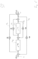
- Fig. 7 shows a schematic block diagram of a decorrelator 70 according to an embodiment.
- Decorrelator 70 comprises at least a part of decorrelator 10, wherein alternatively or in addition at least parts of decorrelator 20, 30 and/or 60 may be arranged.
- Decorrelator 70 may comprise a signal processing stage 56 configured for processing the combined shaped frequency representation 18 or a signal based thereon.
- the combined shaped frequency representation 18 may be considered as a mono signal, i.e., it may represent a single channel. From the received mono signal the processing stage may provide at least signals 58 1 and 58 2 representing a stereo signal.
- a source extender 58 that models the perceptual effect of a spatially extended sound source from a mono signal of a point source and a decorrelated version thereof may be coupled to the decorrelator 70.
- the source extender 58 may comprise filters 64 1 to 64 2 allowing for a source extend modelling based on the stereo signal having signals 58 1 and 58 2 .
- the source extend modeling may be performed, for example, in the frequency domain and may result in stereo output signals 64 1 , e.g., a left channel and 64 2 , e.g., a right channel. It should be noted that the source extender 58 may also form a part of the decorrelator 70.
- Fig. 7 shows a schematic block diagram of source extent processing.
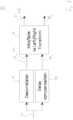
- Fig. 8 shows a schematic block diagram of a processing system 80 according to an embodiment.
- Processing system 80 may comprise decorrelator 10. Alternatively or in addition, decorrelator 20, 30, 60 and/or 70 may be arranged.
- the processing system 80 comprises a processing stage 66 configured for transforming a mid/side decomposed signal 68 to a left/right decomposed signal 72. That is, the mid/side decomposed signal 68 may comprise at least a first signal 74 1 , e.g., representing one of the mid/middle or side portion and a second signal 74 2 representing the other portion.
- the processing stage 66 may be configured for transforming the signals 74 1 to 74 2 and possibly additional signals into at least signals 76 1 to 76 2 representing a left channel and a right channel.
- One channel e.g., the left channel L, may be obtained, for example, by adding the mid component M and the side component M+S; whilst the other, e.g., right channel may be obtained by subtracting one component from the other e.g., M-S.
- both channels may be obtained by using 50 % or a factor of 0.5 thereof, i.e., 0.5(M+S) and 0.5(M-S). Other factors and/or determination rules are possible.
- signal 74 is provided by the decorrelator of the processing system 80.
- the other signal 74 2 may be provided by a delay compensation unit 78 that is connected in parallel to the decorrelator 10 and is configured for also receiving the audio signal 22.
- the delay compensation unit 78 is, thus, connected with the processing stage 66.
- the delay compensation unit 78 may be configured for providing a time delay that is comparable to the decorrelator.
- the delay equals the processing delay introduced by the STFT analysis/synthesis of the decorrelator.
- the decorrelator 10 may provide for additional signal processing leading to a decorrelation such that the signal 74 2 may comprise a similar delay when compared to signal 74 1 .
- the signal 74 2 may be unprocessed with exception of the time delay.
- the decorrelator 10 in the processing system 80 may provide the combined shaped frequency representation as at least one part of the mid/side decomposed signal to the processing stage 66.
- the processing stage 66 may transform the combined shaped frequency representation together with delay signal 74 2 to the left/right decomposed signal in the frequency domain.
- the output of the processing stage 66 may be a UR signal 72.
- the decorrelator 10 itself may produce a mono signal S (Side, component 18), in that respect it is only part of it.
- the direct part M (74 2 ; 74' 2 ) and the decorrelator output S (Signal 18) may become closely coupled, since the signal S will be muted and be "replaced” by an amplified M signal (Signal 74' 2 ).
- both units, decorrelator and "upmixing unit” 66 are closely coupled and so processing stage 66 finally provides the decorrelated stereo signal. If the decorrelator would be operated standalone with mono output, e.g., without processing stage 66, then delay compensated direct signal, without any scaling, should be added directly to the mono output to fill the muted gap and provide a "complete" signal.
- Fig. 8 shows a decorrelator in M/S to UR setup with delay compensation of mono (mid-signal) input.
- Fig. 9 shows a schematic block diagram of a processing system 90 according to an embodiment.
- the processing system 90 comprises a transient suppressor 82 configured for detecting a transient in the audio signal 22 or the frequency representation 14 thereof at an input of the decorrelator.
- the transient suppressor may comprise a transient detection unit 84 configured for receiving the audio signal 22 or the frequency representation thereof.
- the transient detection unit 84 may detect a transient in the audio signal, e.g., by processing the audio signal 22.
- the transient suppressor 82 may further comprise a mute unit 86 configured for receiving the combined shaped frequency representation 18 and for muting the same based on a control signal.
- a same or comparable effect may also be obtained when controlling the decorrelator 10 or the decorrelator contained in the processing system 90 so as to mute the output of the decorrelator. That is, the mute unit 86 may also form a part of the decorrelator.
- signal 74, forming the input of the processing stage 66 may be muted based on a detected transient in the audio signal 22.
- the transient suppressor 82 may be configured for temporarily muting the portion provided by the decorrelator to suppress echoes at the processing stage 66, wherein the echoes may relate to pre-echoes and/or post-echoes.
- a window When operating in the time domain, a window may be used for a soft muting to avoid additional transients to be caused by the muting. If done in the frequency domain, the STFT windowing being described in connection with decorrelators 20, 30 and 60 may provide for such an effect automatically, i.e., in a synergetic manner.
- muting the output of the decorrelator 10 might lead to an unwanted shift in the input energy of the signal processing stage 66.
- an amplifier 82 may be connected between the delay compensation unit 78 and the signal processing stage 66 to temporarily amplify the signal 74 2 to obtain amplified signal 74' 2 .
- Amplification of signal 74 2 may be conditional to muting the output of the decorrelator 10. That is, the transient suppressor 82 may be configured for amplifying the portion of the delay compensation unit 78 corresponding to muting the portion of the decorrelator.
- a level of amplification may be fixed or may be controlled.
- the transient suppressor 82 may be configured for suppressing a detected transient in the audio signal and for suppressing a following transient not earlier than a predefined inhibition time.
- the transient suppressor 82 may comprise a control unit 92 configured for controlling and/or applying a hold time, a hysteresis and/or an inhibition time.
- the hold time may be shorter when compared to the inhibition time.
- the hold time may relate to a time during which the output of the decorrelator 10 is muted responsive to a detected transient, i.e., a property determined by the transient detection unit 84.
- the inhibition time may be longer when compared to the hold time, to avoid unwanted effects.
- the hold counter i.e., the time for muting
- the inhibition time may be at least twice the time, e.g., at least 14, at least 20, at least 30 or 56 blocks or any other time duration.
- the control unit 92 may also provide for a hysteresis to mitigate on/off toggling of transient suppression for audio signals like low rate pulse trains. That is, the inhibition time provided by the control unit 92 may be a first inhibition time.
- the transient suppressor 82 may be configured for restarting the inhibition time as a second inhibition time being longer than the first inhibition time in case a transient occurs during the first inhibition time. That is, even if the hold time has lapsed but the inhibition time has not yet lapsed and in case a new transient is determined (regardless if the hold time has lapsed or not) the inhibition timer may be restarted.
- the restarted inhibition timer may be longer when compared to the cancelled inhibition timer.
- a hold counter and an inhibit counter are both started.
- the transient may be muted until the hold counter has reached its stop count, e.g., 8 blocks. Then, the hold counter may be reset and muting may stop.
- the inhibit counter may reach its stop count/reset much later in time, e.g., 56 blocks. If during said ongoing inhibit counting process a new transient is detected, then just the inhibit counter is restarted, but with a higher stop count value, e.g., 64 blocks. In this way, hysteresis is implemented by conditional switching and stop count modifications. That is, during the inhibit counter running, a new triggering of transient suppression or muting may be deactivated.
- the transient suppressor 82 may be configured for operating in the frequency domain. Alternatively or in addition, the transient suppressor 82 may be configured for muting the portion of the decorrelator for a longer time when compared to a pre-delay of the decorrelator. That is, in case a transient is detected in the audio signal 22, then the mute should still be in effect when the transient arrives at the output of the decorrelator.
- decorrelators operate in the short time Fourier transform (STFT) domain on overlapping transform blocks with short duration.
- STFT short time Fourier transform
- This enables a small processing delay of a few milliseconds, e.g., 2.7 milliseconds assuming a transform size of 256 and 48 kHz sample rate, as opposed to the high delay of the PS/MDS decorrelator as described in [2] or [3] that may arrive at a delay time of 13.3 milliseconds at 48 kHz sample rate.
- the described decorrelators can be implemented using very low computational Allpass filters and may therefore be computationally much more efficient than time domain decorrelation as described in [1] or [2]. If further downstream spectral processing is required or wanted, e.g., a source extent modelling, the described decorrelators may be interfaced directly to this processing stage in the STFT domain to achieve low computational complexity.
- Decorrelators as described herein may thus provide for a short processing delay and a moderate computational complexity. Decorrelators can be combined with additional downstream processing to model audio objects having a spatial dimension, the so-called Spatially Extended Sound Sources (SESS) with a perceptual property of "Source Extend”.
- SESS Spatially Extended Sound Sources
- Fig. 2 and Fig. 9 show preferred embodiments of the present invention.
- the input signal or audio signal (sound of a point source, for example) may be fed into the decorrelator 20 comprising a time-block-wise DFT with, e.g., 256 sample block length and, e.g., 50% overlap.
- the spectral bins of the DFT are time-delayed for a frequency dependent duration, where low frequencies may have a higher delay and high frequencies may have a lower delay.
- delay may be 16 subband samples (42.7 milliseconds at 48 kHz) for low frequencies and may decrease down to 1 subband sample for the highest bins, i.e., z - 1.
- the decrease in delay over time may be linear, logarithmic or otherwise with rounding to integer numbers of subband samples.
- each bin is sent through an Allpass filter, preferably comprising a chain of simple Allpass filters or a nested Allpass filter structure.
- An example Allpass filter is shown in Fig. 4 .
- a different structure is shown in Fig. 5 .
- one possible chain may comprise or consist of four such Allpass filters.
- the parameter g may be chosen to be, for example, 0.7 and the delays M i may be prime numbers. Note that Fig. 4 shows the very first part of the chain, i.e., M 1 .
- the delays may be very low, e.g., prime numbers 1, 2, 3 and 5 or, as another example, 1, 3, 5 and 7.
- a time/frequency envelope shaping may be applied.
- Input signals to the envelope shaping may be the DFT bins directly and their delayed and filtered versions.
- an IDFT with overlap add may synthesize the output signal.
- the output signal may be further processed in time domain to obtain a left/right stereo signal from a mono input signal in a configuration as shown in Fig. 8 .
- the left/right stereo signal can be assembled in DFT frequency domain and further processed in frequency domain, e.g., for a source extent/SESS modelling by fast convolution, if beneficial for overall computational efficiency.
- the alternative embodiment having delays M i may be chosen as prime numbers being approximately 128 times (corresponding the aforementioned downsampling factor) larger than the ones chosen in subband domain, e.g., 131, 257, 383 and 641 (for the set of prime values 1, 2, 3 and 5) or 131, 383, 641 and 907 (for the set of prime values 1, 3, 5 and 7). For different sets of prime values with a different number of prime numbers and/or different prime numbers, corresponding values may be chosen. Further, the alternative embodiment may require an additional STFT to obtain the direct signal input to the time/frequency envelope shaper.
- Fig. 9 shows an example decorrelator in M/S to UR setup with transient handling processing. Aspects of these embodiments are:
- Embodiments of the present invention relate to An/a apparatus/method for decorrelation of an audio signal
- Fig. 10 shows a schematic block diagram of a method 1000 according to an embodiment that may be implemented, for example, by a decorrelator described herein.
- Method 1000 comprises a step 1010 in which a plurality of parts that are based on an audio signal are received.
- each of the received parts is delayed to provide for a plurality of delayed parts.
- 1030 comprises receiving and combining signals being based on the delayed parts of the frequency representation.
- 1040 comprises receiving the frequency representation of the audio signal.
- 1050 comprises adjusting an energy of the delayed parts in respect of the frequency representation of the audio signal.
- 1060 comprises providing a combined shaped frequency representation, e.g., using the envelope shaper 16.
- a first aspect may have a decorrelator comprising: a plurality of delay units 12 , wherein each delay unit 12 is configured for receiving a part 14 1 -14 n of a frequency representation being based on an audio signal 22; wherein each delay unit 12 is configured for delaying the received part 14 1 -14 n to provide a delayed part 14' 1 -14' n ; and an envelope shaper 16 configured for receiving and combining signals being based on the delayed parts 14' 1 -14' n of the frequency representation; for receiving the frequency representation of the audio signal 22; for adjusting an energy of the delayed parts 14' 1 -14' n in respect of the frequency representation of the audio signal 22; and for providing a combined shaped frequency representation.
- different parts 14 1 -14 n of the frequency representation comprise a same or a different number of frequency bins.
- the decorrelator further comprises a phase shifter 26 configured for phase shifting the frequency representation 14 of the audio signal 22; or for phase shifting the audio signal 22 in a time domain to obtain a phase shifted audio signal 22.
- the phase shifter 26 is configured for phase shifting the frequency representation of the audio signal 22 and comprises a plurality of allpass filters, wherein each allpass filter 28 is configured for phase shifting an associated part 14 1 -14 n of the frequency representation of the audio signal 22.
- an allpass filter 28 of the plurality of allpass filter comprises a set of allpass filter structures 40; 50 such as Schroeder IIR filters, being serially connected to each other; wherein the allpass filter structures 40; 50 are adapted for providing different time delays; or wherein the allpass filter structures 40; 50 comprise a nested allpass filter structure.
- a number of allpass filter structures 40; 50 and/or a circuitry of the allpass filter structure is equal or different between different allpass filters 28.
- the different time delays are based on a prime number multiple of a local sampling rate used for obtaining the frequency representation of the audio signal 22.
- the set of allpass filter structures 40; 50 comprises a number of four allpass filter structures 40; 50 and are adapted for providing a delay of 1, 2, 3 and 5 or 1, 3, 5 and 7, respectively.
- a gain factor of the allpass filter 28 is adapted to a value with a magnitude of 0.7 within a tolerance range of e.g., 20 %.
- the phase shifter 26 is configured for phase shifting the audio signal 22 in a time domain; wherein the phase shifter 26 comprises a set of allpass filter structures 40; 50 such as Schroeder IIR filters, being serially connected to each other; wherein the allpass filter structures 40; 50 are adapted for providing different time delays; or wherein the allpass filter structures 40; 50 comprise a nested allpass filter structure.
- allpass filter structures 40; 50 such as Schroeder IIR filters
- the different allpass time delays are based on a prime number multiple of a reciprocal of a sampling rate used for obtaining the frequency representation of the audio signal 22.
- the different time delays are based on a prime number being obtained by multiplying each of a set of minimal prime numbers, e.g., 1, 2, 3 and 5; or 1, 3, 5 and 7, with a downsampling factor used for generating the parts 14 1 -14 n of the frequency representation of the audio signal 22 to obtain an intermediate result; and for using a next prime number with respect to the intermediate result, e.g., as 131, 257, 383, 641 or 131, 383, 641, 907.
- a prime number being obtained by multiplying each of a set of minimal prime numbers, e.g., 1, 2, 3 and 5; or 1, 3, 5 and 7, with a downsampling factor used for generating the parts 14 1 -14 n of the frequency representation of the audio signal 22 to obtain an intermediate result; and for using a next prime number with respect to the intermediate result, e.g., as 131, 257, 383, 641 or 131, 383, 641, 907.
- the decorrelator comprises a first conversion unit 24 for obtaining the frequency representation of the audio signal 22 from the audio signal 22 for the envelope shaper 16; and comprising a second conversion unit 34 for obtaining a frequency representation from the reverberated audio signal 22; wherein the parts 14 1 -14 n of the frequency representation form parts 14 1 -14 n of the frequency representation from the reverberated audio signal 22.
- the parts 14 1 -14 n of the frequency representation comprise an equal or different number of frequency bins.
- the decorrelator is adapted for obtaining a number of 16 parts 14 1 -14 n of the frequency representation.
- the decorrelator is adapted for obtaining the frequency representation with a number of 128 or 129 frequency bins.
- the decorrelator is adapted to additionally implement a same and predefined delay for a subset or all parts 14 1 -14 n of the frequency representation.
- the delay units 12 associated to a spectral part 14 1 -14 n of the plurality of delay units 12 are configured for delaying the associated part 14 1 -14 n of the frequency representation differently when compared to delay units 12 associated to other spectral parts 14 1 -14 n .
- the plurality of delay units 12 is configured for delaying parts 14 1 -14 n of the frequency representation comprising lower frequencies with a higher time delay when compared to parts 14 1 -14 n of the frequency representation comprising higher frequencies.
- a relationship between different time delays is one of linear, logarithmic and/or based on a rounding on subband samples.
- the decorrelator comprises a conversion unit 24 for receiving and converting the audio signal 22 or a reverberated version of the audio signal 22 into the parts 14 1 -14 n by performing a time-block-wise discrete Fourier transform, DFT, or Short-time Fourier transform, STFT; wherein the conversion unit 24 is configured for converting blocks having an overlap of 50 % within a tolerance range.
- DFT time-block-wise discrete Fourier transform
- STFT Short-time Fourier transform
- the decorrelator comprises a conversion unit 24 for receiving and converting the audio signal 22 or a reverberated version of the audio signal 22 into the parts 14 1 -14 n by performing a time-block-wise discrete Fourier transform, DFT, or Short-time Fourier transform, STFT; wherein blocks comprise a block length of 256 samples.
- DFT time-block-wise discrete Fourier transform
- STFT Short-time Fourier transform
- the decorrelator comprises an inverse conversion unit 34 for receiving processed versions of the parts of the frequency representation 14 and for synthesizing an synthesized signal from the processed versions based on an overlap add procedure.
- the envelope shaper 16 is configured for operating in a subband domain and with a temporal resolution of less than 4 ms.
- the envelope shaper 16 is to shape spectral bins in time and/or in frequency individually or as a group, e.g., by implementing an interdependent or an at least groupwise common shaping processing.
- the decorrelator comprises a signal processing stage 66 configured for receiving a signal based on the combined shaped frequency representation as a mono signal and for processing the mono signal at least to a stereo signal.
- the decorrelator comprises a signal processing stage 66 configured for processing the combined shaped frequency representation at least to a stereo audio signal; and for source extend modelling based on the at least stereo signal, e.g., in the frequency domain.
- a twenty-ninth aspect may have processing system comprising: a decorrelator according to one of the previous aspects; and a processing stage 66 for transforming a mid/side decomposed signal to a left/right decomposed signal.
- one portion 74 1 of the mid/side decomposed signal is provided by the decorrelator and the other portion 74 2 is provided by a delay compensation unit 78 being connected in parallel with the decorrelator and connected with the processing stage 66.
- the processing system comprises a transient suppressor 82 configured for detecting a transient in the audio signal 22 or the frequency representation 14 thereof at an input of the decorrelator; wherein the transient suppressor 82 is configured for temporarily muting the portion 74, provided by the decorrelator to suppress echoes at the processing stage.
- the transient suppressor 82 is configured for amplifying the portion of the delay compensation unit by a factor of 2 2 when compared to an unmuted portion of the decorrelator.
- the transient suppressor 82 is configured for suppressing a detected transient and for suppressing a following transient not earlier than a predefined inhibition time.
- the inhibition time is a first inhibition time; wherein the transient suppressor 82 is configured for restarting the inhibition time as a second inhibition time being loner than the first inhibition time in case a transient occurs during the first inhibition time.
- the transient suppressor 82 is configured for operating in the frequency domain.
- the transient suppressor 82 is configured for muting the portion of the decorrelator for a longer time when compared to a pre-delay of the decorrelator.
- a thirty-ninth aspect may have a method comprising: receiving 1010 a plurality of parts of a frequency representation being based on an audio signal; delaying 1020 each of the received parts to provide a plurality of delayed parts; and receiving 1030 and combining signals being based on the delayed parts of the frequency representation; receiving 1040 the frequency representation of the audio signal; adjusting 1050 an energy of the delayed parts in respect of the frequency representation of the audio signal; and providing 1060 a combined shaped frequency representation.
- the method further comprises: detecting a transient in the audio signal 22 or the frequency representation 14 thereof; temporarily muting a portion 74, provided by a decorrelator to suppress echoes at a processing stage.
- a forty-first aspect may have a computer program for performing, when running on a computer or a processor, the method according to the thirty-ninth or fortieth aspect.
- aspects have been described in the context of an apparatus, it is clear that these aspects also represent a description of the corresponding method, where a block or device corresponds to a method step or a feature of a method step. Analogously, aspects described in the context of a method step also represent a description of a corresponding block or item or feature of a corresponding apparatus.
- the inventive encoded audio signal can be stored on a digital storage medium or can be transmitted on a transmission medium such as a wireless transmission medium or a wired transmission medium such as the Internet.
- embodiments of the invention can be implemented in hardware or in software.
- the implementation can be performed using a digital storage medium, for example a floppy disk, a DVD, a CD, a ROM, a PROM, an EPROM, an EEPROM or a FLASH memory, having electronically readable control signals stored thereon, which cooperate (or are capable of cooperating) with a programmable computer system such that the respective method is performed.
- a digital storage medium for example a floppy disk, a DVD, a CD, a ROM, a PROM, an EPROM, an EEPROM or a FLASH memory, having electronically readable control signals stored thereon, which cooperate (or are capable of cooperating) with a programmable computer system such that the respective method is performed.
- Some embodiments according to the invention comprise a data carrier having electronically readable control signals, which are capable of cooperating with a programmable computer system, such that one of the methods described herein is performed.
- embodiments of the present invention can be implemented as a computer program product with a program code, the program code being operative for performing one of the methods when the computer program product runs on a computer.
- the program code may for example be stored on a machine readable carrier.
- inventions comprise the computer program for performing one of the methods described herein, stored on a machine readable carrier.
- an embodiment of the inventive method is, therefore, a computer program having a program code for performing one of the methods described herein, when the computer program runs on a computer.
- a further embodiment of the inventive methods is, therefore, a data carrier (or a digital storage medium, or a computer-readable medium) comprising, recorded thereon, the computer program for performing one of the methods described herein.
- a further embodiment of the inventive method is, therefore, a data stream or a sequence of signals representing the computer program for performing one of the methods described herein.
- the data stream or the sequence of signals may for example be configured to be transferred via a data communication connection, for example via the Internet.
- a further embodiment comprises a processing means, for example a computer, or a programmable logic device, configured to or adapted to perform one of the methods described herein.
- a processing means for example a computer, or a programmable logic device, configured to or adapted to perform one of the methods described herein.
- a further embodiment comprises a computer having installed thereon the computer program for performing one of the methods described herein.
- a programmable logic device for example a field programmable gate array
- a field programmable gate array may cooperate with a microprocessor in order to perform one of the methods described herein.
- the methods are preferably performed by any hardware apparatus.
Landscapes
- Engineering & Computer Science (AREA)
- Physics & Mathematics (AREA)
- Acoustics & Sound (AREA)
- Signal Processing (AREA)
- Multimedia (AREA)
- Computational Linguistics (AREA)
- Audiology, Speech & Language Pathology (AREA)
- Human Computer Interaction (AREA)
- Health & Medical Sciences (AREA)
- Quality & Reliability (AREA)
- Mathematical Physics (AREA)
- Spectroscopy & Molecular Physics (AREA)
- Stereophonic System (AREA)
- Circuit For Audible Band Transducer (AREA)
Applications Claiming Priority (4)
| Application Number | Priority Date | Filing Date | Title |
|---|---|---|---|
| EP21162142 | 2021-03-11 | ||
| EP21203832 | 2021-10-20 | ||
| PCT/EP2022/055983 WO2022189481A1 (en) | 2021-03-11 | 2022-03-09 | Audio decorrelator, processing system and method for decorrelating an audio signal |
| EP22713618.1A EP4305617B1 (de) | 2021-03-11 | 2022-03-09 | Audiodekorrelator, verarbeitungssystem und verfahren zum dekorrelieren eines audiosignals |
Related Parent Applications (1)
| Application Number | Title | Priority Date | Filing Date |
|---|---|---|---|
| EP22713618.1A Division EP4305617B1 (de) | 2021-03-11 | 2022-03-09 | Audiodekorrelator, verarbeitungssystem und verfahren zum dekorrelieren eines audiosignals |
Publications (4)
| Publication Number | Publication Date |
|---|---|
| EP4488998A2 true EP4488998A2 (de) | 2025-01-08 |
| EP4488998A3 EP4488998A3 (de) | 2025-01-22 |
| EP4488998C0 EP4488998C0 (de) | 2026-01-28 |
| EP4488998B1 EP4488998B1 (de) | 2026-01-28 |
Family
ID=80978897
Family Applications (2)
| Application Number | Title | Priority Date | Filing Date |
|---|---|---|---|
| EP22713618.1A Active EP4305617B1 (de) | 2021-03-11 | 2022-03-09 | Audiodekorrelator, verarbeitungssystem und verfahren zum dekorrelieren eines audiosignals |
| EP24214169.5A Active EP4488998B1 (de) | 2021-03-11 | 2022-03-09 | Audiodekorrelator, verarbeitungssystem und verfahren zum dekorrelieren eines audiosignals |
Family Applications Before (1)
| Application Number | Title | Priority Date | Filing Date |
|---|---|---|---|
| EP22713618.1A Active EP4305617B1 (de) | 2021-03-11 | 2022-03-09 | Audiodekorrelator, verarbeitungssystem und verfahren zum dekorrelieren eines audiosignals |
Country Status (13)
| Country | Link |
|---|---|
| US (1) | US20230421979A1 (de) |
| EP (2) | EP4305617B1 (de) |
| JP (1) | JP7832956B2 (de) |
| KR (1) | KR20230160840A (de) |
| AU (1) | AU2022233253B2 (de) |
| BR (1) | BR112023018021A2 (de) |
| CA (1) | CA3211264A1 (de) |
| ES (1) | ES3008258T3 (de) |
| MX (1) | MX2023010502A (de) |
| PL (1) | PL4305617T3 (de) |
| TW (1) | TWI837606B (de) |
| WO (1) | WO2022189481A1 (de) |
| ZA (1) | ZA202308567B (de) |
Families Citing this family (3)
| Publication number | Priority date | Publication date | Assignee | Title |
|---|---|---|---|---|
| WO2025078363A1 (en) * | 2023-10-09 | 2025-04-17 | Fraunhofer-Gesellschaft zur Förderung der angewandten Forschung e.V. | Audio signal decorrelator structure for rendering source extent |
| EP4576071A1 (de) * | 2023-12-19 | 2025-06-25 | Koninklijke Philips N.V. | Erzeugung eines mehrkanaligen audiosignals |
| WO2025132058A1 (en) * | 2023-12-19 | 2025-06-26 | Koninklijke Philips N.V. | Generation of multichannel audio signal |
Family Cites Families (12)
| Publication number | Priority date | Publication date | Assignee | Title |
|---|---|---|---|---|
| CA2992051C (en) * | 2004-03-01 | 2019-01-22 | Dolby Laboratories Licensing Corporation | Reconstructing audio signals with multiple decorrelation techniques and differentially coded parameters |
| US20070038439A1 (en) * | 2003-04-17 | 2007-02-15 | Koninklijke Philips Electronics N.V. Groenewoudseweg 1 | Audio signal generation |
| SE0402649D0 (sv) * | 2004-11-02 | 2004-11-02 | Coding Tech Ab | Advanced methods of creating orthogonal signals |
| US8619998B2 (en) * | 2006-08-07 | 2013-12-31 | Creative Technology Ltd | Spatial audio enhancement processing method and apparatus |
| US8554551B2 (en) | 2008-01-28 | 2013-10-08 | Qualcomm Incorporated | Systems, methods, and apparatus for context replacement by audio level |
| WO2012109384A1 (en) * | 2011-02-10 | 2012-08-16 | Dolby Laboratories Licensing Corporation | Combined suppression of noise and out - of - location signals |
| EP2704142B1 (de) | 2012-08-27 | 2015-09-02 | Fraunhofer-Gesellschaft zur Förderung der angewandten Forschung e.V. | Vorrichtung und Verfahren zur Wiedergabe eines Audiosignals, Vorrichtung und Verfahren zur Erzeugung eines codierten Audiosignals, Computerprogramm und codiertes Audiosignal |
| EP3028274B1 (de) | 2013-07-29 | 2019-03-20 | Dolby Laboratories Licensing Corporation | Vorrichtung und verfahren zum reduzieren zeitlicher artefakte für übergangssignale in einer dekorrelatorschaltung |
| CN111970630B (zh) | 2015-08-25 | 2021-11-02 | 杜比实验室特许公司 | 音频解码器和解码方法 |
| CA3258743A1 (en) * | 2017-07-28 | 2025-10-30 | Fraunhofer-Gesellschaft Zur Foerderung Der Angewandten Forschung E.V. | Apparatus for encoding or decoding an encoded multichannel signal using a filling signal generated by a broad band filter |
| MX2021007109A (es) * | 2018-12-20 | 2021-08-11 | Ericsson Telefon Ab L M | Metodo y aparato para controlar el ocultamiento de perdida de tramas de audio multicanal. |
| TWI866996B (zh) * | 2019-06-26 | 2024-12-21 | 美商杜拜研究特許公司 | 具有改善頻率解析度的低延遲音訊濾波器組 |
-
2022
- 2022-03-09 BR BR112023018021A patent/BR112023018021A2/pt unknown
- 2022-03-09 MX MX2023010502A patent/MX2023010502A/es unknown
- 2022-03-09 EP EP22713618.1A patent/EP4305617B1/de active Active
- 2022-03-09 WO PCT/EP2022/055983 patent/WO2022189481A1/en not_active Ceased
- 2022-03-09 KR KR1020237034379A patent/KR20230160840A/ko active Pending
- 2022-03-09 AU AU2022233253A patent/AU2022233253B2/en active Active
- 2022-03-09 JP JP2023555211A patent/JP7832956B2/ja active Active
- 2022-03-09 EP EP24214169.5A patent/EP4488998B1/de active Active
- 2022-03-09 ES ES22713618T patent/ES3008258T3/es active Active
- 2022-03-09 PL PL22713618.1T patent/PL4305617T3/pl unknown
- 2022-03-09 CA CA3211264A patent/CA3211264A1/en active Pending
- 2022-03-10 TW TW111108843A patent/TWI837606B/zh active
-
2023
- 2023-09-06 ZA ZA2023/08567A patent/ZA202308567B/en unknown
- 2023-09-07 US US18/462,892 patent/US20230421979A1/en active Pending
Non-Patent Citations (4)
| Title |
|---|
| H. PURNHAGENJ. ENGDEGARDJ. RODENL. LILJERYD: "Synthetic Ambience in Parametric Stereo Coding", PAPER, May 2004 (2004-05-01), pages 6074 |
| J. BREEBAARTS. VAN DE PARA. KOHLRAUSCHE. SCHUIJERS: "High-quality Parametric Spatial Audio Coding at Low Bitrates", PAPER, May 2004 (2004-05-01), pages 6072 |
| J. HERREK. KJÖRLINGJ. BREEBAARTC. FALLERS. DISCHH. PURNHAGENJ. KOPPENSJ. HILPERTJ. RÖDÉNW. OOMEN: "MPEG Surround-The ISO/MPEG Standard for Efficient and Compatible Multichannel Audio Coding", J. AUDIO ENG. SOC., vol. 56, no. 11, November 2008 (2008-11-01), pages 932 - 955, XP040508729 |
| W. OOMENE. SCHUIJERSB. DEN BRINKERJ. BREEBAART: "Advances in Parametric Coding for High-Quality Audio", PAPER, March 2003 (2003-03-01), pages 5852 |
Also Published As
| Publication number | Publication date |
|---|---|
| PL4305617T3 (pl) | 2025-04-07 |
| EP4305617B1 (de) | 2024-12-04 |
| AU2022233253A1 (en) | 2023-09-21 |
| EP4488998C0 (de) | 2026-01-28 |
| ZA202308567B (en) | 2024-10-30 |
| WO2022189481A1 (en) | 2022-09-15 |
| JP2024510177A (ja) | 2024-03-06 |
| AU2022233253B2 (en) | 2024-12-12 |
| EP4488998A3 (de) | 2025-01-22 |
| EP4488998B1 (de) | 2026-01-28 |
| BR112023018021A2 (pt) | 2023-10-03 |
| US20230421979A1 (en) | 2023-12-28 |
| KR20230160840A (ko) | 2023-11-24 |
| TWI837606B (zh) | 2024-04-01 |
| TW202242851A (zh) | 2022-11-01 |
| CA3211264A1 (en) | 2022-09-15 |
| EP4305617C0 (de) | 2024-12-04 |
| EP4305617A1 (de) | 2024-01-17 |
| ES3008258T3 (en) | 2025-03-21 |
| JP7832956B2 (ja) | 2026-03-18 |
| MX2023010502A (es) | 2023-10-27 |
Similar Documents
| Publication | Publication Date | Title |
|---|---|---|
| US20230421979A1 (en) | Audio decorrelator, processing system and method for decorrelating an audio signal | |
| EP3594939B1 (de) | Verfahren zur verarbeitung eines audiosignals in übereinstimmung mit einer raumimpulsantwort, signalverarbeitungseinheit, audiocodierer, audiodecodierer und binauraler renderer | |
| CN101138274B (zh) | 用于处理去相干信号或组合信号的设备和方法 | |
| RU2345506C2 (ru) | Многоканальный синтезатор и способ для формирования многоканального выходного сигнала | |
| EP3025520B1 (de) | Verfahren zur verarbeitung eines audiosignals, signalverarbeitungseinheit, binauraler renderer, audiocodierer und audiodecodierer | |
| EP2265042B1 (de) | Erweiterte Verarbeitung auf der Basis einer mit komplexer Exponentialfunktion modulierten Filterbank und adaptive Zeitsignalisierungsverfahren | |
| HK40097269A (en) | Audio decorrelator, processing system and method for decorrelating an audio signal | |
| HK40097269B (en) | Audio decorrelator, processing system and method for decorrelating an audio signal | |
| RU2834349C2 (ru) | Аудиодекоррелятор, система обработки и способ для декорреляции аудиосигнала | |
| CN117157706A (zh) | 用于对音频信号进行解相关的音频解相关器、处理系统和方法 | |
| HK40086480A (en) | Method for processing an audio signal in accordance with a room impulse response, signal processing unit, audio encoder, audio decoder, and binaural renderer | |
| HK1224794B (en) | Method for processing an audio signal in accordance with a room impulse response, signal processing unit, audio encoder, audio decoder, and binaural renderer | |
| HK1152434A (en) | Advanced processing based on a complex-exponential-modulated filterbank and adaptive time signalling methods | |
| HK1225549A1 (en) | Method for processing an audio signal; signal processing unit, binaural renderer, audio encoder and audio decoder | |
| HK1118168B (en) | Temporal envelope shaping of decorrelated signals |
Legal Events
| Date | Code | Title | Description |
|---|---|---|---|
| PUAI | Public reference made under article 153(3) epc to a published international application that has entered the european phase |
Free format text: ORIGINAL CODE: 0009012 |
|
| STAA | Information on the status of an ep patent application or granted ep patent |
Free format text: STATUS: THE APPLICATION HAS BEEN PUBLISHED |
|
| REG | Reference to a national code |
Ref country code: DE Ref legal event code: R079 Free format text: PREVIOUS MAIN CLASS: G10L0021031600 Ipc: G10L0019000000 Ref document number: 602022029581 Country of ref document: DE |
|
| PUAL | Search report despatched |
Free format text: ORIGINAL CODE: 0009013 |
|
| AC | Divisional application: reference to earlier application |
Ref document number: 4305617 Country of ref document: EP Kind code of ref document: P |
|
| AK | Designated contracting states |
Kind code of ref document: A2 Designated state(s): AL AT BE BG CH CY CZ DE DK EE ES FI FR GB GR HR HU IE IS IT LI LT LU LV MC MK MT NL NO PL PT RO RS SE SI SK SM TR |
|
| AK | Designated contracting states |
Kind code of ref document: A3 Designated state(s): AL AT BE BG CH CY CZ DE DK EE ES FI FR GB GR HR HU IE IS IT LI LT LU LV MC MK MT NL NO PL PT RO RS SE SI SK SM TR |
|
| RIC1 | Information provided on ipc code assigned before grant |
Ipc: G10L 19/008 20130101ALI20241219BHEP Ipc: G10L 21/0316 20130101ALI20241219BHEP Ipc: G10L 21/02 20130101ALI20241219BHEP Ipc: G10L 19/02 20130101ALI20241219BHEP Ipc: G10L 19/00 20130101AFI20241219BHEP |
|
| STAA | Information on the status of an ep patent application or granted ep patent |
Free format text: STATUS: REQUEST FOR EXAMINATION WAS MADE |
|
| 17P | Request for examination filed |
Effective date: 20250717 |
|
| GRAP | Despatch of communication of intention to grant a patent |
Free format text: ORIGINAL CODE: EPIDOSNIGR1 |
|
| STAA | Information on the status of an ep patent application or granted ep patent |
Free format text: STATUS: GRANT OF PATENT IS INTENDED |
|
| RIC1 | Information provided on ipc code assigned before grant |
Ipc: G10L 19/00 20130101AFI20250806BHEP Ipc: G10L 19/02 20130101ALI20250806BHEP Ipc: G10L 21/02 20130101ALI20250806BHEP Ipc: G10L 21/0316 20130101ALI20250806BHEP Ipc: G10L 19/008 20130101ALI20250806BHEP |
|
| INTG | Intention to grant announced |
Effective date: 20250822 |
|
| GRAS | Grant fee paid |
Free format text: ORIGINAL CODE: EPIDOSNIGR3 |
|
| GRAA | (expected) grant |
Free format text: ORIGINAL CODE: 0009210 |
|
| STAA | Information on the status of an ep patent application or granted ep patent |
Free format text: STATUS: THE PATENT HAS BEEN GRANTED |
|
| AC | Divisional application: reference to earlier application |
Ref document number: 4305617 Country of ref document: EP Kind code of ref document: P |
|
| AK | Designated contracting states |
Kind code of ref document: B1 Designated state(s): AL AT BE BG CH CY CZ DE DK EE ES FI FR GB GR HR HU IE IS IT LI LT LU LV MC MK MT NL NO PL PT RO RS SE SI SK SM TR |
|
| REG | Reference to a national code |
Ref country code: CH Ref legal event code: F10 Free format text: ST27 STATUS EVENT CODE: U-0-0-F10-F00 (AS PROVIDED BY THE NATIONAL OFFICE) Effective date: 20260128 Ref country code: GB Ref legal event code: FG4D |
|
| REG | Reference to a national code |
Ref country code: DE Ref legal event code: R096 Ref document number: 602022029581 Country of ref document: DE |
|
| REG | Reference to a national code |
Ref country code: IE Ref legal event code: FG4D |
|
| U01 | Request for unitary effect filed |
Effective date: 20260227 |
|
| U07 | Unitary effect registered |
Designated state(s): AT BE BG DE DK EE FI FR IT LT LU LV MT NL PT RO SE SI Effective date: 20260304 |
|
| PGFP | Annual fee paid to national office [announced via postgrant information from national office to epo] |
Ref country code: GB Payment date: 20260324 Year of fee payment: 5 |
|
| PGFP | Annual fee paid to national office [announced via postgrant information from national office to epo] |
Ref country code: AT Payment date: 20260301 Year of fee payment: 5 |