EP4488753A2 - Self calibrating camera device - Google Patents
Self calibrating camera device Download PDFInfo
- Publication number
- EP4488753A2 EP4488753A2 EP24214807.0A EP24214807A EP4488753A2 EP 4488753 A2 EP4488753 A2 EP 4488753A2 EP 24214807 A EP24214807 A EP 24214807A EP 4488753 A2 EP4488753 A2 EP 4488753A2
- Authority
- EP
- European Patent Office
- Prior art keywords
- lens
- sensor
- electroactive polymer
- electrical energy
- camera device
- Prior art date
- Legal status (The legal status is an assumption and is not a legal conclusion. Google has not performed a legal analysis and makes no representation as to the accuracy of the status listed.)
- Withdrawn
Links
Images


Classifications
-
- H—ELECTRICITY
- H04—ELECTRIC COMMUNICATION TECHNIQUE
- H04N—PICTORIAL COMMUNICATION, e.g. TELEVISION
- H04N23/00—Cameras or camera modules comprising electronic image sensors; Control thereof
- H04N23/50—Constructional details
- H04N23/55—Optical parts specially adapted for electronic image sensors; Mounting thereof
-
- G—PHYSICS
- G03—PHOTOGRAPHY; CINEMATOGRAPHY; ANALOGOUS TECHNIQUES USING WAVES OTHER THAN OPTICAL WAVES; ELECTROGRAPHY; HOLOGRAPHY
- G03B—APPARATUS OR ARRANGEMENTS FOR TAKING PHOTOGRAPHS OR FOR PROJECTING OR VIEWING THEM; APPARATUS OR ARRANGEMENTS EMPLOYING ANALOGOUS TECHNIQUES USING WAVES OTHER THAN OPTICAL WAVES; ACCESSORIES THEREFOR
- G03B3/00—Focusing arrangements of general interest for cameras, projectors or printers
- G03B3/04—Focusing arrangements of general interest for cameras, projectors or printers adjusting position of image plane without moving lens
-
- H—ELECTRICITY
- H04—ELECTRIC COMMUNICATION TECHNIQUE
- H04N—PICTORIAL COMMUNICATION, e.g. TELEVISION
- H04N23/00—Cameras or camera modules comprising electronic image sensors; Control thereof
- H04N23/60—Control of cameras or camera modules
- H04N23/69—Control of means for changing angle of the field of view, e.g. optical zoom objectives or electronic zooming
-
- B—PERFORMING OPERATIONS; TRANSPORTING
- B60—VEHICLES IN GENERAL
- B60R—VEHICLES, VEHICLE FITTINGS, OR VEHICLE PARTS, NOT OTHERWISE PROVIDED FOR
- B60R11/00—Arrangements for holding or mounting articles, not otherwise provided for
- B60R11/04—Mounting of cameras operative during drive; Arrangement of controls thereof relative to the vehicle
-
- G—PHYSICS
- G03—PHOTOGRAPHY; CINEMATOGRAPHY; ANALOGOUS TECHNIQUES USING WAVES OTHER THAN OPTICAL WAVES; ELECTROGRAPHY; HOLOGRAPHY
- G03B—APPARATUS OR ARRANGEMENTS FOR TAKING PHOTOGRAPHS OR FOR PROJECTING OR VIEWING THEM; APPARATUS OR ARRANGEMENTS EMPLOYING ANALOGOUS TECHNIQUES USING WAVES OTHER THAN OPTICAL WAVES; ACCESSORIES THEREFOR
- G03B43/00—Testing correct operation of photographic apparatus or parts thereof
-
- G—PHYSICS
- G03—PHOTOGRAPHY; CINEMATOGRAPHY; ANALOGOUS TECHNIQUES USING WAVES OTHER THAN OPTICAL WAVES; ELECTROGRAPHY; HOLOGRAPHY
- G03B—APPARATUS OR ARRANGEMENTS FOR TAKING PHOTOGRAPHS OR FOR PROJECTING OR VIEWING THEM; APPARATUS OR ARRANGEMENTS EMPLOYING ANALOGOUS TECHNIQUES USING WAVES OTHER THAN OPTICAL WAVES; ACCESSORIES THEREFOR
- G03B5/00—Adjustment of optical system relative to image or object surface other than for focusing
- G03B5/08—Swing backs
-
- G—PHYSICS
- G06—COMPUTING OR CALCULATING; COUNTING
- G06T—IMAGE DATA PROCESSING OR GENERATION, IN GENERAL
- G06T7/00—Image analysis
- G06T7/80—Analysis of captured images to determine intrinsic or extrinsic camera parameters, i.e. camera calibration
-
- G—PHYSICS
- G06—COMPUTING OR CALCULATING; COUNTING
- G06T—IMAGE DATA PROCESSING OR GENERATION, IN GENERAL
- G06T7/00—Image analysis
- G06T7/97—Determining parameters from multiple pictures
-
- H—ELECTRICITY
- H04—ELECTRIC COMMUNICATION TECHNIQUE
- H04N—PICTORIAL COMMUNICATION, e.g. TELEVISION
- H04N17/00—Diagnosis, testing or measuring for television systems or their details
- H04N17/002—Diagnosis, testing or measuring for television systems or their details for television cameras
-
- H—ELECTRICITY
- H04—ELECTRIC COMMUNICATION TECHNIQUE
- H04N—PICTORIAL COMMUNICATION, e.g. TELEVISION
- H04N23/00—Cameras or camera modules comprising electronic image sensors; Control thereof
- H04N23/60—Control of cameras or camera modules
- H04N23/68—Control of cameras or camera modules for stable pick-up of the scene, e.g. compensating for camera body vibrations
- H04N23/682—Vibration or motion blur correction
- H04N23/685—Vibration or motion blur correction performed by mechanical compensation
-
- B—PERFORMING OPERATIONS; TRANSPORTING
- B60—VEHICLES IN GENERAL
- B60R—VEHICLES, VEHICLE FITTINGS, OR VEHICLE PARTS, NOT OTHERWISE PROVIDED FOR
- B60R2300/00—Details of viewing arrangements using cameras and displays, specially adapted for use in a vehicle
- B60R2300/40—Details of viewing arrangements using cameras and displays, specially adapted for use in a vehicle characterised by the details of the power supply or the coupling to vehicle components
- B60R2300/402—Image calibration
-
- G—PHYSICS
- G03—PHOTOGRAPHY; CINEMATOGRAPHY; ANALOGOUS TECHNIQUES USING WAVES OTHER THAN OPTICAL WAVES; ELECTROGRAPHY; HOLOGRAPHY
- G03B—APPARATUS OR ARRANGEMENTS FOR TAKING PHOTOGRAPHS OR FOR PROJECTING OR VIEWING THEM; APPARATUS OR ARRANGEMENTS EMPLOYING ANALOGOUS TECHNIQUES USING WAVES OTHER THAN OPTICAL WAVES; ACCESSORIES THEREFOR
- G03B2205/00—Adjustment of optical system relative to image or object surface other than for focusing
- G03B2205/0053—Driving means for the movement of one or more optical element
- G03B2205/0084—Driving means for the movement of one or more optical element using other types of actuators
Definitions
- a variety of sensor types have proven useful for providing enhanced features and control on automotive vehicles. Cameras are useful for detecting objects nearby or in a pathway of a vehicle and providing visual information to a driver.
- the types of cameras included on vehicles typically require that the lens and sensor be aligned with extreme precision.
- Known techniques to achieve such alignment rely on expensive equipment and introduce complexity and delays into the manufacturing process. For example, a five-axis machine controls the relative positions of the lens and sensor during active focus calibration. Once the desired alignment is achieved, at least one cure cycle secures the components in place.
- An illustrative example camera device includes a substrate and a sensor supported on the substrate.
- the sensor is configured to gather image information.
- a lens is situated near the sensor and an electroactive polymer selectively causes relative movement between the sensor and the lens.
- An example embodiment having one or more features of the camera device of the previous paragraph includes a controller that is configured to control electrical energy applied to the electroactive polymer in an amount that causes the relative movement between the sensor and the lens.
- the controller is configured to determine when the camera device is in a calibrated state, determine at least one characteristic of the electrical energy applied to the electroactive polymer when the camera device is in the calibrated state, and maintain the at least one characteristic of the electrical energy to maintain the calibrated state of the camera device.
- the controller is configured to selectively adjust a position of at least one of the sensor or lens relative to the other of the lens or sensor to recalibrate the camera device.
- the electroactive polymer is situated against the substrate and the substrate includes at least one conductive trace for providing electrical energy to the electroactive polymer.
- An example embodiment having one or more features of the camera device of any of the previous paragraphs includes a housing supporting the lens and the substrate.
- the electroactive polymer is situated between the substrate and a reaction surface of the housing, a space occupied by the electroactive polymer changes responsive to electrical energy, the electroactive polymer reacts against the reaction surface as the space occupied by electroactive polymer changes, and a position of the substrate relative to the housing changes as the electroactive polymer reacts against the reaction surface.
- the at least one resilient member biases the substrate toward the reaction surface.
- the housing includes a substrate support, at least one fastener is received through an opening in the substrate support, the at least one fastener is secured to the housing, and the at least one resilient member is associated with the at least one fastener and situated to allow relative movement between the substrate support and the reaction surface.
- the lens is supported in a fixed position relative to the housing.
- An illustrative example method of calibrating a camera device includes providing electrical energy to an electroactive polymer to cause relative movement between a sensor and a lens of the camera device to achieve a first relative orientation between the sensor and the lens, obtaining a first camera image of a reference when the sensor and the lens are in the first relative orientation, determining whether a correspondence between the first camera image and the reference indicates that the camera device is calibrated.
- the correspondence between the first camera image and the reference indicates that the camera device is not calibrated and the method includes providing a different amount of electrical energy to the electroactive polymer to cause relative movement between the sensor and the lens to achieve a second, different relative orientation between the sensor and the lens, obtaining a second camera image of a reference when the sensor and the lens are in the second relative orientation, and determining whether a correspondence between the second camera image and the reference indicates that the camera device is calibrated.
- the electroactive polymer comprises a plurality of portions and providing the electrical energy comprises providing electrical energy having a first characteristic to a first one of the portions and providing electrical energy having a second, different characteristic to a second one of the portions.
- the camera device is supported on a vehicle and the method comprises performing the providing, obtaining and determining a plurality of times during a service life of the camera device.
- An electroactive polymer 40 responds to electrical energy by changing shape or volume.
- the electroactive polymer 40 selectively causes relative movement between the sensor 34 and the lens 32 as it responds to changes in electrical energy provided to it. Such relative movement is useful for focusing or calibrating the camera 20.
- One feature of the illustrated example embodiment is that the electroactive polymer facilitates camera calibration during a manufacturing process and subsequently as may be needed during the service life of the camera 20. This feature is different from many camera devices in which the lens and sensor are set in manner that does not allow subsequent adjustment once the device is made.
- the electroactive polymer 40 includes a plurality of portions or pads situated on the substrate 36.
- the portions of the electroactive polymer 40 are situated between the substrate 36 and a reaction surface 42 on the housing 30.
- the substrate 36 is supported in the housing by a substrate support 44.
- a plurality of fasteners 46 such as screws, hold the substrate support 44 in a desired location within the housing 30.
- Resilient members 48 are associated with the fasteners 46 and the substrate support 44 to allow for some movement of the substrate 36 within the housing.
- the resilient members 48 comprise springs in some embodiments and compressive pads in other embodiments. The resilient members 48 bias the substrate 36 and the portions of electroactive polymer 40 toward the reaction surface 42.
- the camera 20 includes a controller 50 that selectively provides electrical energy to the portions of electroactive polymer 40.
- circuit traces 52 on the substrate 36 conduct the desired amount of electrical energy to the portions of the electroactive polymer 40.
- the controller 50 includes a processor or another computing device and memory.
- the controller 50 selectively provides electrical energy to the portions of electroactive polymer 40, respectively, to achieve a desired orientation between the lens 32 and the sensor 34.
- the controller 50 is able to cause relative movement between the sensor 34 and the lens in three dimensions.
- individually causing the portions of electroactive polymer 40 to expand or contract as schematically shown by the arrows 54 changes the position of the corresponding portion of the substrate 36 relative to the reaction surface 42 of the housing 30.
- the sensor 34 moves with the substrate 36 and therefore the distance between the lens 32 and the sensor 34 is adjustable as schematically shown by the arrows 56 in Figure 4 .
- the controller 50 can control the electrical energy provided to the pads or portions of electroactive polymer 40 to selectively adjust a tilt angle of the sensor 34 as schematically shown by the adjustment arrow 58.
- Calibration begins at 62.
- the sensor 34 obtains an image of a reference, such as a known pattern or series of visible images.
- the controller 50 determines whether the image obtained by the sensor 34 corresponds to the reference at 66. If there is insufficient correspondence between the captured image information and the reference, the controller changes the electrical energy provided to at least one of the portions of electroactive polymer 40 at 68.
- the sensor obtains another image at 64 and the controller compares the most recently obtained image with the reference at 66. This process continues until there is sufficient correspondence between the captured image and the reference to indicate that the camera is properly calibrated.
- the controller 50 stores at least one characteristic of the electrical energy provided to the respective portions of electroactive polymer 40.
- Example stored characteristics include voltage and current. The stored characteristics are subsequently used by the controller 50 to place or keep the sensor 34 and the lens 32 properly aligned to maintain calibration of the camera 20.
- One feature of the illustrated embodiment is that it is possible to perform such calibration during a manufacturing process and subsequently at various times during the service life of the camera 20. For example, when the camera 20 is supported on the vehicle 22 it is possible for temperature conditions or impact to adversely affect the components of the camera 20 causing the camera 20 to lose calibration or to operate in a less-than-ideal manner.
- the controller 50 can execute the calibration process summarized above to recalibrate the camera 20. Previous camera configurations without the electroactive polymer 40 could not be recalibrated because the lens 32 and sensor 34 are fixed in a manner that does not allow subsequent adjustment.
- electroactive polymer materials there are known electroactive polymer materials and those skilled in the art who have the benefit of this description will be able to select an appropriate material for their particular situation.
- An electroactive polymer is considered advantageous over a piezoelectric material, for example, because electroactive polymers have better strain percentage properties allowing for more adjustment or relative movement between the lens 32 and the sensor 34.
- the senor 34 and substrate 36 are moveable relative to the housing 30 while the lens remains stationary relative to the housing 30 in the illustrated example embodiment, other embodiments include a moveable lens 32.
Landscapes
- Engineering & Computer Science (AREA)
- Physics & Mathematics (AREA)
- General Physics & Mathematics (AREA)
- Multimedia (AREA)
- Signal Processing (AREA)
- Theoretical Computer Science (AREA)
- Computer Vision & Pattern Recognition (AREA)
- General Health & Medical Sciences (AREA)
- Biomedical Technology (AREA)
- Health & Medical Sciences (AREA)
- Mechanical Engineering (AREA)
- Studio Devices (AREA)
- Lens Barrels (AREA)
Abstract
Description
- A variety of sensor types have proven useful for providing enhanced features and control on automotive vehicles. Cameras are useful for detecting objects nearby or in a pathway of a vehicle and providing visual information to a driver. The types of cameras included on vehicles typically require that the lens and sensor be aligned with extreme precision. Known techniques to achieve such alignment rely on expensive equipment and introduce complexity and delays into the manufacturing process. For example, a five-axis machine controls the relative positions of the lens and sensor during active focus calibration. Once the desired alignment is achieved, at least one cure cycle secures the components in place.
- Known camera assembly techniques have another drawback in addition to the added expense associated with the specialized equipment and time delays mentioned above. Once the camera sensor and lens are cured in position, future adjustment or calibration is not possible. Given the wide range of environmental conditions vehicles and their components are exposed to overtime, camera devices are subject to material creep, printed circuit board warping, stresses from mechanical shock and vibration, and deterioration of the adhesive that secures the lens and sensor in the calibrated position. It is not possible to adjust or recalibrate the camera over time, which introduces additional expenses if a camera is replaced. If not replaced, the camera simply remains in a less-than-ideal calibration state.
- An illustrative example camera device includes a substrate and a sensor supported on the substrate. The sensor is configured to gather image information. A lens is situated near the sensor and an electroactive polymer selectively causes relative movement between the sensor and the lens.
- An example embodiment having one or more features of the camera device of the previous paragraph includes a controller that is configured to control electrical energy applied to the electroactive polymer in an amount that causes the relative movement between the sensor and the lens.
- In an example embodiment having one or more features of the camera device of any of the previous paragraphs, the controller is configured to determine when the camera device is in a calibrated state, determine at least one characteristic of the electrical energy applied to the electroactive polymer when the camera device is in the calibrated state, and maintain the at least one characteristic of the electrical energy to maintain the calibrated state of the camera device.
- In an example embodiment having one or more features of the camera device of any of the previous paragraphs, the controller is configured to selectively adjust a position of at least one of the sensor or lens relative to the other of the lens or sensor to recalibrate the camera device.
- In an example embodiment having one or more features of the camera device of any of the previous paragraphs, the electroactive polymer is situated against the substrate and the substrate includes at least one conductive trace for providing electrical energy to the electroactive polymer.
- An example embodiment having one or more features of the camera device of any of the previous paragraphs includes a housing supporting the lens and the substrate. The electroactive polymer is situated between the substrate and a reaction surface of the housing, a space occupied by the electroactive polymer changes responsive to electrical energy, the electroactive polymer reacts against the reaction surface as the space occupied by electroactive polymer changes, and a position of the substrate relative to the housing changes as the electroactive polymer reacts against the reaction surface.
- An example embodiment having one or more features of the camera device of any of the previous paragraphs at least one resilient member associated with the substrate for allowing relative movement between the substrate and the reaction surface as the electroactive polymer reacts against the reaction surface.
- In an example embodiment having one or more features of the camera device of any of the previous paragraphs, the at least one resilient member biases the substrate toward the reaction surface.
- In an example embodiment having one or more features of the camera device of any of the previous paragraphs, the electroactive polymer comprises a plurality of portions supported on the substrate and the at least one resilient member comprises a plurality of members respectively associated with the portions of the electroactive polymer.
- In an example embodiment having one or more features of the camera device of any of the previous paragraphs, the housing includes a substrate support, at least one fastener is received through an opening in the substrate support, the at least one fastener is secured to the housing, and the at least one resilient member is associated with the at least one fastener and situated to allow relative movement between the substrate support and the reaction surface.
- In an example embodiment having one or more features of the camera device of any of the previous paragraphs, the lens is supported in a fixed position relative to the housing.
- In an example embodiment having one or more features of the camera device of any of the previous paragraphs, the relative movement includes at least one of a change in a distance between the sensor and the lens and a change in an angle of tilt between the sensor and the lens.
- In an example embodiment having one or more features of the camera device of any of the previous paragraphs, the electroactive polymer comprises a plurality of portions supported on the substrate in respective locations, each of the portions responds to an amount of electrical energy applied to it, and different amounts of electrical energy applied to the portions, respectively, causes different relative movements between the sensor and the lens.
- An illustrative example method of calibrating a camera device includes providing electrical energy to an electroactive polymer to cause relative movement between a sensor and a lens of the camera device to achieve a first relative orientation between the sensor and the lens, obtaining a first camera image of a reference when the sensor and the lens are in the first relative orientation, determining whether a correspondence between the first camera image and the reference indicates that the camera device is calibrated.
- In an example embodiment having one or more features of the method of the previous paragraph, the correspondence between the first camera image and the reference indicates that the camera device is not calibrated and the method includes providing a different amount of electrical energy to the electroactive polymer to cause relative movement between the sensor and the lens to achieve a second, different relative orientation between the sensor and the lens, obtaining a second camera image of a reference when the sensor and the lens are in the second relative orientation, and determining whether a correspondence between the second camera image and the reference indicates that the camera device is calibrated.
- In an example embodiment having one or more features of the method of any of the previous paragraphs, the electroactive polymer comprises a plurality of portions and providing the electrical energy comprises providing electrical energy having a first characteristic to a first one of the portions and providing electrical energy having a second, different characteristic to a second one of the portions.
- In an example embodiment having one or more features of the method of any of the previous paragraphs, the relative movement between the sensor and the lens changes at least one of a distance between the sensor and the lens and an angle of the sensor relative to the lens.
- In an example embodiment having one or more features of the method of any of the previous paragraphs, the camera device is supported on a vehicle and the method comprises performing the providing, obtaining and determining a plurality of times during a service life of the camera device.
- An illustrative example camera device includes a substrate, sensor means supported on the substrate for gathering image information, a lens near the sensor, an electroactive polymer that selectively causes relative movement between the sensor and the lens, and control means for controlling electrical energy applied to the electroactive polymer in an amount that causes the relative movement between the sensor and the lens.
- In an example embodiment having one or more features of the camera device of the previous paragraph, the control means is configured to selectively adjust a position of at least one of the sensor or lens relative to the other of the lens or sensor for recalibrating the camera device.
- The various features and advantages of at least one disclosed example embodiment will become apparent to those skilled in the art from the following detailed description. The drawings that accompany the detailed description can be briefly described as follows.
-
-
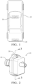
Figure 1 diagrammatically illustrates an example vehicle including at least one camera designed according to an embodiment of this invention. -
Figure 2 diagrammatically illustrates selected an example camera device. -
Figure 3 is a cross-sectional illustration taken along the lines 3-3 inFigure 2 . -
Figure 4 schematically illustrates selected features of an example camera device. -
Figure 5 is a flowchart diagram summarizing a method of calibrating a camera device. -
Figure 1 schematically illustratescamera devices 20 supported on avehicle 22. Thecamera devices 20 may be used for a variety of detection or image gathering purposes, such as detecting objects or conditions in a vicinity of the vehicle. - As shown in
Figures 2-4 , thecameras 20 each include ahousing 30 that supports alens 32. Asensor 34 that is configured to capture images or gather image information is supported on asubstrate 36. In the illustrated example embodiment, thesubstrate 36 is a generally planar printed circuit board. Thesensor 34 is secured in a fixed position on thesubstrate 36, which is accomplished by soldering thesensor 34 in place in some embodiments. - An
electroactive polymer 40 responds to electrical energy by changing shape or volume. Theelectroactive polymer 40 selectively causes relative movement between thesensor 34 and thelens 32 as it responds to changes in electrical energy provided to it. Such relative movement is useful for focusing or calibrating thecamera 20. One feature of the illustrated example embodiment is that the electroactive polymer facilitates camera calibration during a manufacturing process and subsequently as may be needed during the service life of thecamera 20. This feature is different from many camera devices in which the lens and sensor are set in manner that does not allow subsequent adjustment once the device is made. - In the illustrated example embodiment, the
electroactive polymer 40 includes a plurality of portions or pads situated on thesubstrate 36. The portions of theelectroactive polymer 40 are situated between thesubstrate 36 and areaction surface 42 on thehousing 30. Thesubstrate 36 is supported in the housing by asubstrate support 44. A plurality offasteners 46, such as screws, hold thesubstrate support 44 in a desired location within thehousing 30.Resilient members 48 are associated with thefasteners 46 and thesubstrate support 44 to allow for some movement of thesubstrate 36 within the housing. Theresilient members 48 comprise springs in some embodiments and compressive pads in other embodiments. Theresilient members 48 bias thesubstrate 36 and the portions ofelectroactive polymer 40 toward thereaction surface 42. - As shown in
Figure 4 , thecamera 20 includes acontroller 50 that selectively provides electrical energy to the portions ofelectroactive polymer 40. In this example, circuit traces 52 on thesubstrate 36 conduct the desired amount of electrical energy to the portions of theelectroactive polymer 40. - The
controller 50 includes a processor or another computing device and memory. Thecontroller 50 selectively provides electrical energy to the portions ofelectroactive polymer 40, respectively, to achieve a desired orientation between thelens 32 and thesensor 34. By changing the amount of electrical energy provided to each portion of electroactive polymer, thecontroller 50 is able to cause relative movement between thesensor 34 and the lens in three dimensions. For example, individually causing the portions ofelectroactive polymer 40 to expand or contract as schematically shown by thearrows 54 changes the position of the corresponding portion of thesubstrate 36 relative to thereaction surface 42 of thehousing 30. Thesensor 34 moves with thesubstrate 36 and therefore the distance between thelens 32 and thesensor 34 is adjustable as schematically shown by thearrows 56 inFigure 4 . Additionally, thecontroller 50 can control the electrical energy provided to the pads or portions ofelectroactive polymer 40 to selectively adjust a tilt angle of thesensor 34 as schematically shown by theadjustment arrow 58. - Causing relative movement between the
lens 32 and thesensor 34 facilitates calibrating thecamera 20. An example calibration technique is summarized in theflow chart 60 ofFigure 5 . Calibration begins at 62. At 64, thesensor 34 obtains an image of a reference, such as a known pattern or series of visible images. Thecontroller 50 determines whether the image obtained by thesensor 34 corresponds to the reference at 66. If there is insufficient correspondence between the captured image information and the reference, the controller changes the electrical energy provided to at least one of the portions ofelectroactive polymer 40 at 68. The sensor obtains another image at 64 and the controller compares the most recently obtained image with the reference at 66. This process continues until there is sufficient correspondence between the captured image and the reference to indicate that the camera is properly calibrated. Once calibrated, at 70, thecontroller 50 stores at least one characteristic of the electrical energy provided to the respective portions ofelectroactive polymer 40. Example stored characteristics include voltage and current. The stored characteristics are subsequently used by thecontroller 50 to place or keep thesensor 34 and thelens 32 properly aligned to maintain calibration of thecamera 20. - One feature of the illustrated embodiment is that it is possible to perform such calibration during a manufacturing process and subsequently at various times during the service life of the
camera 20. For example, when thecamera 20 is supported on thevehicle 22 it is possible for temperature conditions or impact to adversely affect the components of thecamera 20 causing thecamera 20 to lose calibration or to operate in a less-than-ideal manner. When a suitable reference is available, such as at a vehicle service center, thecontroller 50 can execute the calibration process summarized above to recalibrate thecamera 20. Previous camera configurations without theelectroactive polymer 40 could not be recalibrated because thelens 32 andsensor 34 are fixed in a manner that does not allow subsequent adjustment. - There are known electroactive polymer materials and those skilled in the art who have the benefit of this description will be able to select an appropriate material for their particular situation. An electroactive polymer is considered advantageous over a piezoelectric material, for example, because electroactive polymers have better strain percentage properties allowing for more adjustment or relative movement between the
lens 32 and thesensor 34. - Although the
sensor 34 andsubstrate 36 are moveable relative to thehousing 30 while the lens remains stationary relative to thehousing 30 in the illustrated example embodiment, other embodiments include amoveable lens 32. - The preceding description is exemplary rather than limiting in nature. Variations and modifications to the disclosed examples may become apparent to those skilled in the art that do not necessarily depart from the essence of this invention. The scope of legal protection given to this invention can only be determined by studying the following claims.
Claims (15)
- A method of calibrating a camera device (20), the method comprising:providing electrical energy to an electroactive polymer (40) comprising a plurality of electroactive polymer pads disposed on a first side of a substrate (36) at locations distal from one another in a horizontal plane to cause relative movement in a vertical dimension between a sensor (34), disposed on the first side of the substrate, and a lens (32) of the camera device (20) to achieve a first relative orientation between the sensor (34) and the lens (32), each location of the plurality of electroactive polymer pads including a single electroactive polymer pad that couples the first side of the substrate (36) to a reaction surface (42) of a housing (30) supporting the lens (32) and the substrate (36), each single electroactive polymer pad configured to expand or contract in a direction normal to the reaction surface (42) of the housing (30) to adjust a separation distance in the vertical dimension or a tilt angle of the sensor (34) relative to the lens (32);determining that the camera device (20) is in a calibrated state by:obtaining a first camera image of a reference when the sensor (34) and the lens (32) are in the first relative orientation associated with a first amount of electrical energy applied to the plurality of electroactive polymer pads; anddetermining whether a correspondence between the first camera image and the reference indicates that the camera device (20) is calibrated;determining at least one characteristic of the electrical energy applied to the plurality of electroactive polymer pads when the camera device (20) is in the calibrated state; andmaintaining the at least one characteristic of the electrical energy to maintain the calibrated state of the camera device (20).
- The method of claim 1, further comprising:
storing, within a memory, the at least one characteristic of the electrical energy provided to the electroactive polymer (40) when the camera device (20) is in the calibrated state. - The method of claim 1 or 2, wherein:the correspondence between the first camera image and the reference indicates that the camera device (20) is not calibrated; andthe method further comprises:providing a different amount of electrical energy to at least one of the plurality of electroactive polymer pads to cause the relative movement between the sensor (34) and the lens (32) to achieve a second, different relative orientation between the sensor (34) and the lens (32) in the separation distance or the tilt angle;obtaining a second camera image of a reference when the sensor (34) and the lens (32) are in the second relative orientation; and determining whether a correspondence between the second camera image and the reference indicates that the camera device (20) is calibrated.
- The method of any one of claims 1 to 3, wherein:
providing the electrical energy comprises providing electrical energy having a first characteristic to a first one of the plurality of electroactive polymer pads and providing electrical energy having a second, different characteristic to a second one of the plurality of electroactive polymer pads. - The method of any one of claims 1 to 4, wherein the relative movement between the sensor (34) and the lens (32) changes both the separation distance between the sensor (34) and the lens (32) and the tilt angle of the sensor relative to the lens (32).
- The method of any one of claims 1 to 5, wherein the camera device (20) is supported on a vehicle and the method comprises performing the providing, obtaining, and determining a plurality of times during a service life of the camera device (20).
- The method of any one of claims 1 to 6, wherein the at least one characteristic of the electrical energy applied to the plurality of electroactive polymer pads when the camera device (20) is in the calibrated state includes at least one of a voltage applied to one or more of the plurality of electroactive polymer pads or a current applied to one or more of the plurality of electroactive polymer pads.
- The method of any one of claims 1 to 7, wherein:providing electrical energy to the plurality of electroactive polymer pads comprises providing an amount of electrical energy to each respective pad of the plurality of electroactive polymer pads; anddifferent amounts of electrical energy respectively provided to the respective pads of the plurality of electroactive polymer pads causes different relative movements between the sensor (34) and the lens (32).
- An apparatus, the apparatus comprising a controller (50) for maintaining calibration of a camera device (20) for a vehicle, the controller (50) having at least one processor configured to:produce relative movement in a vertical dimension between a lens (32) and a sensor (34) of the camera device (20) by applying electrical energy to multiple electroactive polymer pads located distal from one another in a horizontal plane within a polymer layer (40) of the camera device (20);adjusting the electrical energy that produces the relative movement to maintain a separation distance in the vertical dimension or a tilt angle between the sensor (34) and the lens (32);determine that the camera device (20) is in a calibrated state by:obtaining a first camera image of a reference when the sensor (34) and the lens (32) are in a first relative orientation associated with a first amount of electrical energy applied to the multiple electroactive polymer pads; anddetermining whether a correspondence between the first camera image and the reference indicates that the camera device (20) is calibrated;determine at least one characteristic of the electrical energy applied to the multiple electroactive polymer pads when the camera device (20) is in the calibrated state; andmaintain the at least one characteristic of the electrical energy to maintain the calibrated state of the camera device (20).
- The apparatus of claim 9, wherein the at least one processor is further configured to:
store, within a memory of the apparatus, the at least one characteristic of the electrical energy applied to the multiple electroactive polymer pads when the camera device (20) is in the calibrated state. - The apparatus of claim 9 or 10, wherein the at least one characteristic of the electrical energy applied to the multiple electroactive polymer pads when the camera device (20) is in the calibrated state includes at least one of a voltage applied to one or more of the multiple electroactive polymer pads or a current applied to one or more of the multiple electroactive polymer pads.
- The apparatus of any one of claims 9 to 11, wherein:the correspondence between the first camera image and the reference indicates that the camera device (20) is not calibrated; andthe at least one processor is further configured to:apply a different amount of electrical energy to at least one pad of the multiple electroactive polymer pads to cause the relative movement between the sensor (34) and the lens (32) to achieve a second relative orientation between the sensor (34) and the lens (32) with respect to the separation distance or the tilt angle;obtain a second camera image of a reference when the sensor (34) and the lens are in the second relative orientation; anddetermine whether a correspondence between the second camera image and the reference indicates that the camera device (20) is calibrated.
- The apparatus of any one of claims 9 to 12, wherein adjusting the electrical energy that produces the relative movement to maintain the separation distance or the tilt angle between the sensor and the lens (32) in the calibrated state comprises selectively adjusting a position of at least one of the sensor (34) or lens relative to the other of the sensor (34) or the lens (32) to recalibrate the camera device (20).
- The apparatus of any one of claims 9 to 13, wherein the relative movement includes both a change in the separation distance between the sensor (34) and the lens (32) and a change in the tilt angle between the sensor (34) and the lens (32).
- The apparatus of any one of claims 9 to 14, wherein:applying electrical energy to the multiple electroactive polymer pads comprises applying an amount of electrical energy to each respective pad of the multiple electroactive polymer pads; anddifferent amounts of electrical energy respectively applied to the respective pads of the multiple electroactive polymer pads causes different relative movements between the sensor (34) and the lens (32).
Applications Claiming Priority (2)
| Application Number | Priority Date | Filing Date | Title |
|---|---|---|---|
| US16/386,959 US20200336667A1 (en) | 2019-04-17 | 2019-04-17 | Self calibrating camera device |
| EP20167126.0A EP3726289B1 (en) | 2019-04-17 | 2020-03-31 | Self calibrating camera device |
Related Parent Applications (2)
| Application Number | Title | Priority Date | Filing Date |
|---|---|---|---|
| EP20167126.0A Division EP3726289B1 (en) | 2019-04-17 | 2020-03-31 | Self calibrating camera device |
| EP20167126.0A Division-Into EP3726289B1 (en) | 2019-04-17 | 2020-03-31 | Self calibrating camera device |
Publications (2)
| Publication Number | Publication Date |
|---|---|
| EP4488753A2 true EP4488753A2 (en) | 2025-01-08 |
| EP4488753A3 EP4488753A3 (en) | 2025-04-02 |
Family
ID=70110106
Family Applications (2)
| Application Number | Title | Priority Date | Filing Date |
|---|---|---|---|
| EP24214807.0A Withdrawn EP4488753A3 (en) | 2019-04-17 | 2020-03-31 | Self calibrating camera device |
| EP20167126.0A Active EP3726289B1 (en) | 2019-04-17 | 2020-03-31 | Self calibrating camera device |
Family Applications After (1)
| Application Number | Title | Priority Date | Filing Date |
|---|---|---|---|
| EP20167126.0A Active EP3726289B1 (en) | 2019-04-17 | 2020-03-31 | Self calibrating camera device |
Country Status (3)
| Country | Link |
|---|---|
| US (2) | US20200336667A1 (en) |
| EP (2) | EP4488753A3 (en) |
| CN (2) | CN114205504B (en) |
Families Citing this family (1)
| Publication number | Priority date | Publication date | Assignee | Title |
|---|---|---|---|---|
| US20200336667A1 (en) | 2019-04-17 | 2020-10-22 | Aptiv Technologies Limited | Self calibrating camera device |
Family Cites Families (19)
| Publication number | Priority date | Publication date | Assignee | Title |
|---|---|---|---|---|
| JP2006343506A (en) * | 2005-06-08 | 2006-12-21 | Sony Corp | LENS DRIVE DEVICE AND IMAGING DEVICE |
| US7299109B2 (en) * | 2005-07-28 | 2007-11-20 | Idx, Inc. | Vending machine having promotional features |
| US7702227B2 (en) * | 2005-08-16 | 2010-04-20 | Canon Kabushiki Kaisha | Optical device having blur correction function |
| US7777782B2 (en) * | 2005-11-04 | 2010-08-17 | Nokia Corporation | Stabilization of an image produced by optics |
| US7893965B2 (en) * | 2007-08-08 | 2011-02-22 | Bayer Materialscience Ag | Optical lens image stabilization systems |
| KR20100037950A (en) * | 2008-10-02 | 2010-04-12 | 삼성전기주식회사 | Wafer level packaging image sensor module having a lens actuator and the mathod of manufacturing the same |
| TW201115205A (en) * | 2009-03-18 | 2011-05-01 | Artificial Muscle Inc | Wafer level optical system |
| US20110221950A1 (en) | 2010-03-12 | 2011-09-15 | Doeke Jolt Oostra | Camera device, wafer scale package |
| WO2013109869A1 (en) * | 2012-01-20 | 2013-07-25 | Magna Electronics, Inc. | Vehicle vision system with free positional virtual panoramic view |
| US9634225B2 (en) * | 2012-12-17 | 2017-04-25 | Apple Inc. | Artificial muscle camera lens actuator |
| US9158090B2 (en) | 2013-12-20 | 2015-10-13 | Apple Inc. | Camera module with artificial muscle actuator and structure for focusing during assembly |
| CN104580859B (en) * | 2014-12-22 | 2019-03-22 | 格科微电子(上海)有限公司 | The assembly method and camera module of camera module |
| CN105842960A (en) * | 2015-01-13 | 2016-08-10 | 宁波舜宇光电信息有限公司 | Image module group, lens seat structure, and design method for lens seat structure |
| US9891612B2 (en) | 2015-05-05 | 2018-02-13 | Hand Held Products, Inc. | Intermediate linear positioning |
| US20170277187A1 (en) * | 2016-02-29 | 2017-09-28 | Optecks, Llc | Aerial Three-Dimensional Scanner |
| CN106713897B (en) * | 2017-02-27 | 2018-03-09 | 驭势(上海)汽车科技有限公司 | Binocular camera and the method for self-calibrating for binocular camera |
| CN208739247U (en) * | 2018-10-15 | 2019-04-12 | 深圳市聚力光电科技有限公司 | a camera module |
| US12134352B2 (en) * | 2018-10-26 | 2024-11-05 | Motherson Innovations Company Limited | Hybrid interior mirror with error recognition |
| US20200336667A1 (en) | 2019-04-17 | 2020-10-22 | Aptiv Technologies Limited | Self calibrating camera device |
-
2019
- 2019-04-17 US US16/386,959 patent/US20200336667A1/en not_active Abandoned
-
2020
- 2020-03-31 EP EP24214807.0A patent/EP4488753A3/en not_active Withdrawn
- 2020-03-31 EP EP20167126.0A patent/EP3726289B1/en active Active
- 2020-04-16 CN CN202111520429.XA patent/CN114205504B/en active Active
- 2020-04-16 CN CN202010298849.7A patent/CN111835948B/en active Active
-
2022
- 2022-01-06 US US17/647,290 patent/US11800229B2/en active Active
Also Published As
| Publication number | Publication date |
|---|---|
| EP4488753A3 (en) | 2025-04-02 |
| CN114205504A (en) | 2022-03-18 |
| US20200336667A1 (en) | 2020-10-22 |
| CN111835948B (en) | 2021-12-31 |
| CN111835948A (en) | 2020-10-27 |
| CN114205504B (en) | 2024-07-02 |
| US20220132039A1 (en) | 2022-04-28 |
| EP3726289B1 (en) | 2025-01-01 |
| US11800229B2 (en) | 2023-10-24 |
| EP3726289A1 (en) | 2020-10-21 |
Similar Documents
| Publication | Publication Date | Title |
|---|---|---|
| US8218018B2 (en) | Optical apparatus | |
| EP2081391B1 (en) | Method for adjusting position of image sensor, method and apparatus for manufacturing a camera module, and camera module | |
| KR102003043B1 (en) | Flexible printed circuit board and small camera apparatus having the same | |
| JP4806026B2 (en) | Digital imaging with stabilized images | |
| US7181083B2 (en) | System and method for configuring an imaging tool | |
| KR20130108283A (en) | Camera apparatus | |
| US20120026387A1 (en) | Actuator, Drive Device, and Imaging Device | |
| CN107079090B (en) | UAV and camera components | |
| US20120044368A1 (en) | Optical image system | |
| US9485400B2 (en) | Camera module and method for the production thereof | |
| KR20110074979A (en) | Optical image stabilization including shape memory alloy actuator | |
| US20170141669A1 (en) | Anti-tilt electromagnetic motor | |
| US12235513B2 (en) | Optical element driving system | |
| US11800229B2 (en) | Camera calibration utilizing electroactive polymer | |
| US20050110873A1 (en) | Image pickup apparatus | |
| EP4268444A1 (en) | Apparatus for a dynamic vision sensor and method for adjusting a dynamic vision sensor | |
| US20090135260A1 (en) | Method and System for Image Stabilization | |
| US20250280199A1 (en) | Piezo-actuated platforms for image sensor stabilization | |
| US11698572B2 (en) | Device for controlling multi-axial tilt of camera lens and method therefor | |
| US5686991A (en) | Positioning apparatus having the interferometer and accelerometer positioned such that there signals are in phase | |
| KR20230120178A (en) | Camera module with magnetic field interference prevention sturcure | |
| US20210103204A1 (en) | Lens barrel, camera body, camera system | |
| CN111988507B (en) | Assembly method and assembly apparatus of image capture device | |
| JP2014052601A (en) | Camera module and information processor | |
| KR101742620B1 (en) | System for measuring actuator of cellular phone's camera |
Legal Events
| Date | Code | Title | Description |
|---|---|---|---|
| PUAI | Public reference made under article 153(3) epc to a published international application that has entered the european phase |
Free format text: ORIGINAL CODE: 0009012 |
|
| STAA | Information on the status of an ep patent application or granted ep patent |
Free format text: STATUS: THE APPLICATION HAS BEEN PUBLISHED |
|
| AC | Divisional application: reference to earlier application |
Ref document number: 3726289 Country of ref document: EP Kind code of ref document: P |
|
| AK | Designated contracting states |
Kind code of ref document: A2 Designated state(s): AL AT BE BG CH CY CZ DE DK EE ES FI FR GB GR HR HU IE IS IT LI LT LU LV MC MK MT NL NO PL PT RO RS SE SI SK SM TR |
|
| REG | Reference to a national code |
Ref country code: DE Ref legal event code: R079 Free format text: PREVIOUS MAIN CLASS: G03B0043000000 Ipc: G03B0003040000 |
|
| PUAL | Search report despatched |
Free format text: ORIGINAL CODE: 0009013 |
|
| AK | Designated contracting states |
Kind code of ref document: A3 Designated state(s): AL AT BE BG CH CY CZ DE DK EE ES FI FR GB GR HR HU IE IS IT LI LT LU LV MC MK MT NL NO PL PT RO RS SE SI SK SM TR |
|
| RIC1 | Information provided on ipc code assigned before grant |
Ipc: G03B 43/00 20210101ALI20250225BHEP Ipc: G03B 5/08 20210101ALI20250225BHEP Ipc: G03B 3/04 20210101AFI20250225BHEP |
|
| STAA | Information on the status of an ep patent application or granted ep patent |
Free format text: STATUS: THE APPLICATION IS DEEMED TO BE WITHDRAWN |
|
| 18D | Application deemed to be withdrawn |
Effective date: 20251003 |