EP4488711A1 - Ground clutter suppression and runway imaging via radar ground mapping - Google Patents
Ground clutter suppression and runway imaging via radar ground mapping Download PDFInfo
- Publication number
- EP4488711A1 EP4488711A1 EP24185105.4A EP24185105A EP4488711A1 EP 4488711 A1 EP4488711 A1 EP 4488711A1 EP 24185105 A EP24185105 A EP 24185105A EP 4488711 A1 EP4488711 A1 EP 4488711A1
- Authority
- EP
- European Patent Office
- Prior art keywords
- aesa
- radar
- linear arrays
- linear
- linear array
- Prior art date
- Legal status (The legal status is an assumption and is not a legal conclusion. Google has not performed a legal analysis and makes no representation as to the accuracy of the status listed.)
- Pending
Links
Images





Classifications
-
- G—PHYSICS
- G01—MEASURING; TESTING
- G01S—RADIO DIRECTION-FINDING; RADIO NAVIGATION; DETERMINING DISTANCE OR VELOCITY BY USE OF RADIO WAVES; LOCATING OR PRESENCE-DETECTING BY USE OF THE REFLECTION OR RERADIATION OF RADIO WAVES; ANALOGOUS ARRANGEMENTS USING OTHER WAVES
- G01S13/00—Systems using the reflection or reradiation of radio waves, e.g. radar systems; Analogous systems using reflection or reradiation of waves whose nature or wavelength is irrelevant or unspecified
- G01S13/88—Radar or analogous systems specially adapted for specific applications
- G01S13/93—Radar or analogous systems specially adapted for specific applications for anti-collision purposes
- G01S13/933—Radar or analogous systems specially adapted for specific applications for anti-collision purposes of aircraft or spacecraft
-
- G—PHYSICS
- G01—MEASURING; TESTING
- G01S—RADIO DIRECTION-FINDING; RADIO NAVIGATION; DETERMINING DISTANCE OR VELOCITY BY USE OF RADIO WAVES; LOCATING OR PRESENCE-DETECTING BY USE OF THE REFLECTION OR RERADIATION OF RADIO WAVES; ANALOGOUS ARRANGEMENTS USING OTHER WAVES
- G01S13/00—Systems using the reflection or reradiation of radio waves, e.g. radar systems; Analogous systems using reflection or reradiation of waves whose nature or wavelength is irrelevant or unspecified
- G01S13/88—Radar or analogous systems specially adapted for specific applications
- G01S13/89—Radar or analogous systems specially adapted for specific applications for mapping or imaging
- G01S13/90—Radar or analogous systems specially adapted for specific applications for mapping or imaging using synthetic aperture techniques, e.g. synthetic aperture radar [SAR] techniques
-
- G—PHYSICS
- G01—MEASURING; TESTING
- G01S—RADIO DIRECTION-FINDING; RADIO NAVIGATION; DETERMINING DISTANCE OR VELOCITY BY USE OF RADIO WAVES; LOCATING OR PRESENCE-DETECTING BY USE OF THE REFLECTION OR RERADIATION OF RADIO WAVES; ANALOGOUS ARRANGEMENTS USING OTHER WAVES
- G01S13/00—Systems using the reflection or reradiation of radio waves, e.g. radar systems; Analogous systems using reflection or reradiation of waves whose nature or wavelength is irrelevant or unspecified
- G01S13/02—Systems using reflection of radio waves, e.g. primary radar systems; Analogous systems
- G01S13/06—Systems determining position data of a target
- G01S13/42—Simultaneous measurement of distance and other co-ordinates
- G01S13/44—Monopulse radar, i.e. simultaneous lobing
- G01S13/4463—Monopulse radar, i.e. simultaneous lobing using phased arrays
-
- G—PHYSICS
- G01—MEASURING; TESTING
- G01S—RADIO DIRECTION-FINDING; RADIO NAVIGATION; DETERMINING DISTANCE OR VELOCITY BY USE OF RADIO WAVES; LOCATING OR PRESENCE-DETECTING BY USE OF THE REFLECTION OR RERADIATION OF RADIO WAVES; ANALOGOUS ARRANGEMENTS USING OTHER WAVES
- G01S13/00—Systems using the reflection or reradiation of radio waves, e.g. radar systems; Analogous systems using reflection or reradiation of waves whose nature or wavelength is irrelevant or unspecified
- G01S13/02—Systems using reflection of radio waves, e.g. primary radar systems; Analogous systems
- G01S13/06—Systems determining position data of a target
- G01S13/42—Simultaneous measurement of distance and other co-ordinates
- G01S13/44—Monopulse radar, i.e. simultaneous lobing
- G01S13/4472—Monopulse radar, i.e. simultaneous lobing with means specially adapted to airborne monopulse systems
-
- G—PHYSICS
- G01—MEASURING; TESTING
- G01S—RADIO DIRECTION-FINDING; RADIO NAVIGATION; DETERMINING DISTANCE OR VELOCITY BY USE OF RADIO WAVES; LOCATING OR PRESENCE-DETECTING BY USE OF THE REFLECTION OR RERADIATION OF RADIO WAVES; ANALOGOUS ARRANGEMENTS USING OTHER WAVES
- G01S13/00—Systems using the reflection or reradiation of radio waves, e.g. radar systems; Analogous systems using reflection or reradiation of waves whose nature or wavelength is irrelevant or unspecified
- G01S13/87—Combinations of radar systems, e.g. primary radar and secondary radar
- G01S13/872—Combinations of primary radar and secondary radar
-
- G—PHYSICS
- G01—MEASURING; TESTING
- G01S—RADIO DIRECTION-FINDING; RADIO NAVIGATION; DETERMINING DISTANCE OR VELOCITY BY USE OF RADIO WAVES; LOCATING OR PRESENCE-DETECTING BY USE OF THE REFLECTION OR RERADIATION OF RADIO WAVES; ANALOGOUS ARRANGEMENTS USING OTHER WAVES
- G01S13/00—Systems using the reflection or reradiation of radio waves, e.g. radar systems; Analogous systems using reflection or reradiation of waves whose nature or wavelength is irrelevant or unspecified
- G01S13/88—Radar or analogous systems specially adapted for specific applications
- G01S13/95—Radar or analogous systems specially adapted for specific applications for meteorological use
- G01S13/953—Radar or analogous systems specially adapted for specific applications for meteorological use mounted on aircraft
-
- G—PHYSICS
- G01—MEASURING; TESTING
- G01S—RADIO DIRECTION-FINDING; RADIO NAVIGATION; DETERMINING DISTANCE OR VELOCITY BY USE OF RADIO WAVES; LOCATING OR PRESENCE-DETECTING BY USE OF THE REFLECTION OR RERADIATION OF RADIO WAVES; ANALOGOUS ARRANGEMENTS USING OTHER WAVES
- G01S7/00—Details of systems according to groups G01S13/00, G01S15/00, G01S17/00
- G01S7/02—Details of systems according to groups G01S13/00, G01S15/00, G01S17/00 of systems according to group G01S13/00
- G01S7/03—Details of HF subsystems specially adapted therefor, e.g. common to transmitter and receiver
-
- G—PHYSICS
- G01—MEASURING; TESTING
- G01S—RADIO DIRECTION-FINDING; RADIO NAVIGATION; DETERMINING DISTANCE OR VELOCITY BY USE OF RADIO WAVES; LOCATING OR PRESENCE-DETECTING BY USE OF THE REFLECTION OR RERADIATION OF RADIO WAVES; ANALOGOUS ARRANGEMENTS USING OTHER WAVES
- G01S7/00—Details of systems according to groups G01S13/00, G01S15/00, G01S17/00
- G01S7/02—Details of systems according to groups G01S13/00, G01S15/00, G01S17/00 of systems according to group G01S13/00
- G01S7/41—Details of systems according to groups G01S13/00, G01S15/00, G01S17/00 of systems according to group G01S13/00 using analysis of echo signal for target characterisation; Target signature; Target cross-section
- G01S7/414—Discriminating targets with respect to background clutter
-
- H—ELECTRICITY
- H01—ELECTRIC ELEMENTS
- H01Q—ANTENNAS, i.e. RADIO AERIALS
- H01Q1/00—Details of, or arrangements associated with, antennas
- H01Q1/27—Adaptation for use in or on movable bodies
- H01Q1/28—Adaptation for use in or on aircraft, missiles, satellites, or balloons
-
- H—ELECTRICITY
- H01—ELECTRIC ELEMENTS
- H01Q—ANTENNAS, i.e. RADIO AERIALS
- H01Q21/00—Antenna arrays or systems
- H01Q21/0006—Particular feeding systems
- H01Q21/0037—Particular feeding systems linear waveguide fed arrays
- H01Q21/0043—Slotted waveguides
-
- H—ELECTRICITY
- H01—ELECTRIC ELEMENTS
- H01Q—ANTENNAS, i.e. RADIO AERIALS
- H01Q21/00—Antenna arrays or systems
- H01Q21/06—Arrays of individually energised antenna units similarly polarised and spaced apart
- H01Q21/061—Two dimensional planar arrays
-
- H—ELECTRICITY
- H01—ELECTRIC ELEMENTS
- H01Q—ANTENNAS, i.e. RADIO AERIALS
- H01Q25/00—Antennas or antenna systems providing at least two radiating patterns
- H01Q25/02—Antennas or antenna systems providing at least two radiating patterns providing sum and difference patterns
-
- H—ELECTRICITY
- H01—ELECTRIC ELEMENTS
- H01Q—ANTENNAS, i.e. RADIO AERIALS
- H01Q3/00—Arrangements for changing or varying the orientation or the shape of the directional pattern of the waves radiated from an antenna or antenna system
- H01Q3/26—Arrangements for changing or varying the orientation or the shape of the directional pattern of the waves radiated from an antenna or antenna system varying the relative phase or relative amplitude of energisation between two or more active radiating elements; varying the distribution of energy across a radiating aperture
- H01Q3/2605—Array of radiating elements provided with a feedback control over the element weights, e.g. adaptive arrays
- H01Q3/2611—Means for null steering; Adaptive interference nulling
- H01Q3/2629—Combination of a main antenna unit with an auxiliary antenna unit
- H01Q3/2635—Combination of a main antenna unit with an auxiliary antenna unit the auxiliary unit being composed of a plurality of antennas
-
- G—PHYSICS
- G01—MEASURING; TESTING
- G01S—RADIO DIRECTION-FINDING; RADIO NAVIGATION; DETERMINING DISTANCE OR VELOCITY BY USE OF RADIO WAVES; LOCATING OR PRESENCE-DETECTING BY USE OF THE REFLECTION OR RERADIATION OF RADIO WAVES; ANALOGOUS ARRANGEMENTS USING OTHER WAVES
- G01S13/00—Systems using the reflection or reradiation of radio waves, e.g. radar systems; Analogous systems using reflection or reradiation of waves whose nature or wavelength is irrelevant or unspecified
- G01S13/02—Systems using reflection of radio waves, e.g. primary radar systems; Analogous systems
- G01S2013/0236—Special technical features
- G01S2013/0245—Radar with phased array antenna
-
- G—PHYSICS
- G01—MEASURING; TESTING
- G01S—RADIO DIRECTION-FINDING; RADIO NAVIGATION; DETERMINING DISTANCE OR VELOCITY BY USE OF RADIO WAVES; LOCATING OR PRESENCE-DETECTING BY USE OF THE REFLECTION OR RERADIATION OF RADIO WAVES; ANALOGOUS ARRANGEMENTS USING OTHER WAVES
- G01S13/00—Systems using the reflection or reradiation of radio waves, e.g. radar systems; Analogous systems using reflection or reradiation of waves whose nature or wavelength is irrelevant or unspecified
- G01S13/02—Systems using reflection of radio waves, e.g. primary radar systems; Analogous systems
- G01S2013/0236—Special technical features
- G01S2013/0245—Radar with phased array antenna
- G01S2013/0254—Active array antenna
-
- G—PHYSICS
- G01—MEASURING; TESTING
- G01S—RADIO DIRECTION-FINDING; RADIO NAVIGATION; DETERMINING DISTANCE OR VELOCITY BY USE OF RADIO WAVES; LOCATING OR PRESENCE-DETECTING BY USE OF THE REFLECTION OR RERADIATION OF RADIO WAVES; ANALOGOUS ARRANGEMENTS USING OTHER WAVES
- G01S13/00—Systems using the reflection or reradiation of radio waves, e.g. radar systems; Analogous systems using reflection or reradiation of waves whose nature or wavelength is irrelevant or unspecified
- G01S13/02—Systems using reflection of radio waves, e.g. primary radar systems; Analogous systems
- G01S2013/0236—Special technical features
- G01S2013/0245—Radar with phased array antenna
- G01S2013/0263—Passive array antenna
-
- G—PHYSICS
- G01—MEASURING; TESTING
- G01S—RADIO DIRECTION-FINDING; RADIO NAVIGATION; DETERMINING DISTANCE OR VELOCITY BY USE OF RADIO WAVES; LOCATING OR PRESENCE-DETECTING BY USE OF THE REFLECTION OR RERADIATION OF RADIO WAVES; ANALOGOUS ARRANGEMENTS USING OTHER WAVES
- G01S13/00—Systems using the reflection or reradiation of radio waves, e.g. radar systems; Analogous systems using reflection or reradiation of waves whose nature or wavelength is irrelevant or unspecified
- G01S13/02—Systems using reflection of radio waves, e.g. primary radar systems; Analogous systems
- G01S2013/0236—Special technical features
- G01S2013/0272—Multifunction radar
-
- H—ELECTRICITY
- H01—ELECTRIC ELEMENTS
- H01Q—ANTENNAS, i.e. RADIO AERIALS
- H01Q1/00—Details of, or arrangements associated with, antennas
- H01Q1/27—Adaptation for use in or on movable bodies
- H01Q1/28—Adaptation for use in or on aircraft, missiles, satellites, or balloons
- H01Q1/281—Nose antennas
-
- H—ELECTRICITY
- H01—ELECTRIC ELEMENTS
- H01Q—ANTENNAS, i.e. RADIO AERIALS
- H01Q21/00—Antenna arrays or systems
- H01Q21/06—Arrays of individually energised antenna units similarly polarised and spaced apart
- H01Q21/08—Arrays of individually energised antenna units similarly polarised and spaced apart the units being spaced along or adjacent to a rectilinear path
Definitions
- GCS ground clutter suppression
- PWS predictive wind shear
- Such antennas have a main beam gain slope that is a function of the angle between the beam peak and the first radiation pattern down looking null adjacent to the main beam.
- Very low peak side lobe levels (SLL) (-30 dBp 1-way) are required to realize -60 dB 2-way monostatic radar SLLs required for existing PWS GCS.
- slotted waveguide antenna arrays are exploited to differentially detect runway landing PWS by aggressively attenuating undesirable ground returns that masks the low radar cross section (RCS) wind shear, a very time transient meteorological phenomenon.
- RCS radar cross section
- Analog AESAs commonly transmit in uniform aperture illumination to maximize effective isotropic radiated power (EIRP) to maximize power on target in order to maximize radar range / radar performance index (RPI).
- EIRP effective isotropic radiated power
- RPI radar performance index
- Maximum EIRP requires a uniform aperture illumination to maximize the aggregate PA power; uniform illumination dictates -13.5 dBp SLLs in accordance to array theory.
- Uniform illumination in transmit (Tx) and -30 dBp sidelobes in receive (Rx) results in a -43.5 dBp 2-way SLL; 16.5 worse than that used for current state PWS GCS algorithms.
- embodiments of the inventive concepts disclosed herein are directed to a radar system with an AESA and at least one ground mapping linear array that operate on a separate receive channel and send I/Q digital terrain mapping data to a radar processing unit.
- the linear arrays provide constant ground mapping.
- the AESA may have more than one panel. Panels may be arranged as a chevron with the linear arrays disposed at the periphery.
- the AESA and linear arrays may be configured as a radar interferometer for track location and / or geolocation.
- the linear arrays may be configured as near field probes for insitu calibration.
- inventive concepts are not limited in their application to the arrangement of the components or steps or methodologies set forth in the following description or illustrated in the drawings.
- inventive concepts disclosed herein may be practiced without these specific details.
- well-known features may not be described in detail to avoid unnecessarily complicating the instant disclosure.
- inventive concepts disclosed herein are capable of other embodiments or of being practiced or carried out in various ways. Also, it is to be understood that the phraseology and terminology employed herein is for the purpose of description and should not be regarded as limiting.
- a letter following a reference numeral is intended to reference an embodiment of a feature or element that may be similar, but not necessarily identical, to a previously described element or feature bearing the same reference numeral (e.g., 1, 1a, 1b).
- reference numeral e.g. 1, 1a, 1b
- Such shorthand notations are used for purposes of convenience only, and should not be construed to limit the inventive concepts disclosed herein in any way unless expressly stated to the contrary.
- any reference to "one embodiment,” or “some embodiments” means that a particular element, feature, structure, or characteristic described in connection with the embodiment is included in at least one embodiment of the inventive concepts disclosed herein.
- the appearances of the phrase “in at least one embodiment” in the specification does not necessarily refer to the same embodiment.
- Embodiments of the inventive concepts disclosed may include one or more of the features expressly described or inherently present herein, or any combination or sub-combination of two or more such features.
- embodiments of the inventive concepts disclosed herein are directed to a radar system with an AESA and at least one ground mapping linear array that operate on a separate receive channel and send I/Q digital terrain mapping data to a radar processing unit.
- the linear arrays provide constant ground mapping.
- the AESA may have more than one panel. Panels may be arranged as a chevron, or as a tri-panel architecture, etc., with the linear arrays disposed at the periphery.
- the AESA and linear arrays may be configured as a radar interferometer for track location and / or geolocation.
- the linear arrays may be configured as near field probes for insitu calibration.
- the antenna system 100 includes an AESA 102 operating as a multimode radar.
- the AESA 102 may be configured for weather, PWS, fail detection, HAC, volcanic ash, bird strike, or the like; runway imaging for landing and taxiway obstacle detection / avoidance; autonomous flight; etc.
- the antennas system 100 also includes one or more linear arrays 104, 106 disposed vertically, and proximal to the AESA 102.
- the linear arrays 104, 106 may be slotted wave guide linear array sticks with CSC 2 beam in elevation and a fan beam in azimuth. In at least one embodiment, the linear arrays 104, 106 may operate on a separate receive channel.
- the linear arrays 104, 106 send I/Q terrain mapping data to a radar processing unit 108, configured by non-transitory processor executable code to identify ground clutter.
- the linear arrays 104, 106 and radar processing unit 108 produce a continuous ground mapping through all mission phases, regardless of the state of the AESA 102.
- the linear arrays 104, 106 (and corresponding linear array channels) may be both Rx and Tx for both ground mapping and insitu AESA calibration.
- the linear arrays 104, 106 contiguously map terrain in front of and below an aircraft.
- the processor 108 may then remove ground clutter identified via the linear arrays 104, 106 from the main beam of the AESA 102 to realize GCS. Because the linear arrays 104, 106 produce a fan beam, they illuminate greater terrain in azimuth.
- the ground map gain threshold can be adjusted via a variable gain amplifier (VGA) or automatic gain control (AGC) as necessary.
- VGA variable gain amplifier
- AGC automatic gain control
- the ground beam may be fixed or staring. Adjunct terrain maps may be synched with the generated terrain map for increased fidelity.
- the linear arrays 104, 106 may be embodied in AESA antennas. AESA linear arrays 104, 106 may change the fan beam radiation patterns as a function of time, mission phase, etc.
- An aircraft radar system with an AESA may produce an elevation radiation pattern 200 and azimuthal radiation pattern 202 with a main beam and sidelobes.
- a linear array may produce an elevation fan beam 300 and azimuthal fan beam 302.
- An antenna with an AESA and a linear array may produce both a multimode radiation pattern 400 and a fan beam 402 simultaneously.
- the multimode radiation pattern 400 and fan beam 402 may be configured to operate in separate channels.
- the linear array may be configured to operate only in a receive mode.
- the radar system 506 includes an AESA main radar antenna 500 and two ground mapping linear array antennas 502, 504 disposed vertically along edges of the AESA main radar antenna 500.
- the linear array antennas 502, 504 may comprise slotted waveguide sticks.
- the linear arrays 502, 504 may comprise one dimensional AESAs, embedded within the greater AESA main radar antenna 500.
- the linear arrays 502, 504 may be printed circuit board based linear arrays or AESA beam scanned linear arrays.
- Linear array AESAs may produce radiation patterns that can be dynamically changed over time based on flight mission phasing, radar mode, etc.
- a radar processing unit 508 configures the AESA main radar antenna 500 and the linear arrays 502, 504, and receives signals from the AESA main radar antenna 500 and the linear arrays 502, 504, via corresponding Tx/Rx modules 510, 512, 514.
- the Tx/Rx modules 510, 512, 514 may include filters and amplifiers such VGAs and AGCs.
- the relative Tx EIRP and Rx total gain for the linear arrays 502, 504 may be dynamically adjusted relative the AESA main beam. It may be appreciated that the driving and receive electronics may be conventional RF PCB electronics, or implemented as one or more systems on a chip.
- each linear array 502, 504 may be offset relative to the corresponding aircraft's fuselage as needed for specific functionality requirements.
- the linear arrays 502, 504 may be limited to Rx only to reduce component complexity.
- the linear arrays 502, 504 may be repurposed as Rx and Tx near field probes for insitu calibration of the AESA main radar antenna 500.
- the linear arrays 502, 504 may be configured for one dimensional monopulse operation.
- Monopulse capabilities in elevation
- the linear arrays 502, 504, potentially in conjunction with the AESA's main radar antenna 500 may be configured as a radar interferometer for precision track location, geolocation, and the like.
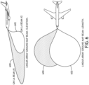
- FIG. 6 environmental representations of radiation patterns according to an exemplary embodiment are shown.
- the system may produce a plurality of partially overlapping fan beams 600, 602.
- a system with an AESA radar antenna and two or more linear arrays may produce both a multimode AESA main beam 700 radiation pattern and partially overlapping fan beams 702, 704 simultaneously.
- the AESA main beam 700 and fan beams 702, 704 may be configured to operate in separate channels.
- the linear arrays may be configured to operate only in a receive mode.
- Overlapping fan beams 702, 704 enhance ground coverage, both in elevation and azimuth. Mechanical positioning of linear arrays may optimize the azimuthal and elevation ground mapping fan beam 702, 704 overlap for a given aircraft type.
- the fan beams 702, 704 may be of the same pattern synthesis or two unique beam depending on systems requirements. While embodiments represented include two linear arrays and two fan beams 702, 704, it may be appreciated that three or more linear arrays radar channels are envisioned.
- the system includes at least two AESA panels 814, 816 organized at angles to each other (e.g., a chevron).
- the AESA panels 814, 816 may individually produce corresponding main beam radiation patterns 800, 804 and a synthetic aperture main beam 802.
- the antenna system also includes a plurality of linear arrays 818, 820, 822, 824.
- Peripheral linear arrays 818, 822 may be disposed at the periphery of the AESA panels 814, 816 while coincident linear arrays 820, 824 are disposed at the interface between the AESA panels 814, 816.
- the coincident linear arrays 820, 824 may be rotated to look forward with respect to the corresponding aircraft's fuselage.
- the peripheral linear arrays 818, 822 are disposed to look perpendicular to the proximal AESA panel 814, 816.
- peripheral linear arrays 818, 822 each produce a corresponding ground mapping beam 806, 812. Furthermore, the coincident linear arrays 820, 824 produce at least partially overlapping, forward facing, ground mapping beams 808, 810.
- An antenna system including angularly offset AESA panels 814, 816 and corresponding linear arrays 818, 820, 822, 824 enables robust, greater than ⁇ 90° azimuthal GSC.
- more than two AESA panels 814, 816 and corresponding linear arrays 818, 820, 822, 824 are envisioned.
- embodiments may employ three AESA panels 814, 816 with linear arrays 818, 820, 822, 824 disposed between the AESA panels 814, 816 and at the periphery of the AESA panels 814, 816.
- Embodiments of the present disclosure enable superior GCS with AESA radar systems, identification and elimination of ground targets for predictive windshear detection, and creation of high-resolution ground maps to distinguish between weather phenomenon and ground.
- the ground mapping beam is highly suited for airport / runway environment mapping; a CSC 2 beam is an attractive beam shape option as it covers the entire length of a runway during an aircraft landing approach. Other, more unique linear beam shapes can be utilized if required.
Landscapes
- Engineering & Computer Science (AREA)
- Remote Sensing (AREA)
- Radar, Positioning & Navigation (AREA)
- Physics & Mathematics (AREA)
- General Physics & Mathematics (AREA)
- Computer Networks & Wireless Communication (AREA)
- Electromagnetism (AREA)
- Aviation & Aerospace Engineering (AREA)
- Astronomy & Astrophysics (AREA)
- Radar Systems Or Details Thereof (AREA)
Abstract
A radar system includes an AESA and at least one ground mapping linear array (818, 822) that operate on a separate receive channel and send I/Q digital terrain mapping data to a radar processing unit (108). The linear arrays provide constant ground mapping. The AESA may have more than one panel (814, 816). Panels may be arranged as a chevron with the linear arrays disposed at the periphery. The AESA and linear arrays may be configured as a radar interferometer for track location and / or geolocation. The linear arrays may be configured as near field probes for insitu calibration.
Description
- Traditional commercial airborne weather radar systems utilize a simple ground clutter suppression (GCS) algorithm for predictive wind shear (PWS) detection that relies on high-performance mechanically driven slotted waveguide array antennas. Such antennas have a main beam gain slope that is a function of the angle between the beam peak and the first radiation pattern down looking null adjacent to the main beam. Very low peak side lobe levels (SLL) (-30 dBp 1-way) are required to realize -60 dB 2-way monostatic radar SLLs required for existing PWS GCS.
- The characteristics of slotted waveguide antenna arrays are exploited to differentially detect runway landing PWS by aggressively attenuating undesirable ground returns that masks the low radar cross section (RCS) wind shear, a very time transient meteorological phenomenon.
- Analog AESAs commonly transmit in uniform aperture illumination to maximize effective isotropic radiated power (EIRP) to maximize power on target in order to maximize radar range / radar performance index (RPI). Maximum EIRP requires a uniform aperture illumination to maximize the aggregate PA power; uniform illumination dictates -13.5 dBp SLLs in accordance to array theory. Uniform illumination in transmit (Tx) and -30 dBp sidelobes in receive (Rx) results in a -43.5 dBp 2-way SLL; 16.5 worse than that used for current state PWS GCS algorithms.
- An analog AESA with low Tx SLLs severely penalizes EIRP. The degradation is even worse for large AESA scan angles off boresight. It would be advantageous to have a radar system that is affective for attenuating
- In one aspect, embodiments of the inventive concepts disclosed herein are directed to a radar system with an AESA and at least one ground mapping linear array that operate on a separate receive channel and send I/Q digital terrain mapping data to a radar processing unit. The linear arrays provide constant ground mapping.
- In a further aspect, the AESA may have more than one panel. Panels may be arranged as a chevron with the linear arrays disposed at the periphery.
- In a further aspect, the AESA and linear arrays may be configured as a radar interferometer for track location and / or geolocation.
- In a further aspect, the linear arrays may be configured as near field probes for insitu calibration.
- It is to be understood that both the foregoing general description and the following detailed description are exemplary and explanatory only and should not restrict the scope of the claims. The accompanying drawings, which are incorporated in and constitute a part of the specification, illustrate exemplary embodiments of the inventive concepts disclosed herein and together with the general description, serve to explain the principles.
- The numerous advantages of the embodiments of the inventive concepts disclosed herein may be better understood by those skilled in the art by reference to the accompanying figures in which:
- FIG. 1
- shows a block diagram of an antenna system according to an exemplary embodiment;
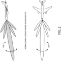
- FIG. 2
- shows environmental representations of a radiation pattern;
- FIG. 3
- shows environmental representations of a radiation pattern;
- FIG. 4
- shows environmental representations of a radiation pattern according to an exemplary embodiment;
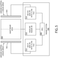
- FIG. 5
- shows a block diagram of a radar system according to an exemplary embodiment;
- FIG. 6
- shows environmental representations of radiation patterns according to an exemplary embodiment;
- FIG. 7
- shows environmental representations of a radiation pattern according to an exemplary embodiment;
- FIG. 8
- shows a block diagram of an antenna system according to an exemplary embodiment;
- Before explaining various embodiments of the inventive concepts disclosed herein in detail, it is to be understood that the inventive concepts are not limited in their application to the arrangement of the components or steps or methodologies set forth in the following description or illustrated in the drawings. In the following detailed description of embodiments of the instant inventive concepts, numerous specific details are set forth in order to provide a more thorough understanding of the inventive concepts. However, it will be apparent to one of ordinary skill in the art having the benefit of the instant disclosure that the inventive concepts disclosed herein may be practiced without these specific details. In other instances, well-known features may not be described in detail to avoid unnecessarily complicating the instant disclosure. The inventive concepts disclosed herein are capable of other embodiments or of being practiced or carried out in various ways. Also, it is to be understood that the phraseology and terminology employed herein is for the purpose of description and should not be regarded as limiting.
- As used herein a letter following a reference numeral is intended to reference an embodiment of a feature or element that may be similar, but not necessarily identical, to a previously described element or feature bearing the same reference numeral (e.g., 1, 1a, 1b). Such shorthand notations are used for purposes of convenience only, and should not be construed to limit the inventive concepts disclosed herein in any way unless expressly stated to the contrary.
- Further, unless expressly stated to the contrary, "or" refers to an inclusive or and not to an exclusive or. For example, a condition A or B is satisfied by anyone of the following: A is true (or present) and B is false (or not present), A is false (or not present) and B is true (or present), and both A and B are true (or present).
- In addition, use of "a" or "an" are employed to describe elements and components of embodiments of the instant inventive concepts. This is done merely for convenience and to give a general sense of the inventive concepts, and "a" and "an" are intended to include one or at least one and the singular also includes the plural unless it is obvious that it is meant otherwise.
- Also, while various components may be depicted as being connected directly, direct connection is not a requirement. Components may be in data communication with intervening components that are not illustrated or described.
- Finally, as used herein any reference to "one embodiment," or "some embodiments" means that a particular element, feature, structure, or characteristic described in connection with the embodiment is included in at least one embodiment of the inventive concepts disclosed herein. The appearances of the phrase "in at least one embodiment" in the specification does not necessarily refer to the same embodiment. Embodiments of the inventive concepts disclosed may include one or more of the features expressly described or inherently present herein, or any combination or sub-combination of two or more such features.
- Broadly, embodiments of the inventive concepts disclosed herein are directed to a radar system with an AESA and at least one ground mapping linear array that operate on a separate receive channel and send I/Q digital terrain mapping data to a radar processing unit. The linear arrays provide constant ground mapping. The AESA may have more than one panel. Panels may be arranged as a chevron, or as a tri-panel architecture, etc., with the linear arrays disposed at the periphery. The AESA and linear arrays may be configured as a radar interferometer for track location and / or geolocation. The linear arrays may be configured as near field probes for insitu calibration.
- Referring to
FIG. 1 , a block diagram of anantenna system 100 according to an exemplary embodiment is shown. Theantenna system 100 includes an AESA 102 operating as a multimode radar. The AESA 102 may be configured for weather, PWS, fail detection, HAC, volcanic ash, bird strike, or the like; runway imaging for landing and taxiway obstacle detection / avoidance; autonomous flight; etc. - The
antennas system 100 also includes one or morelinear arrays AESA 102. Thelinear arrays linear arrays linear arrays radar processing unit 108, configured by non-transitory processor executable code to identify ground clutter. Thelinear arrays radar processing unit 108 produce a continuous ground mapping through all mission phases, regardless of the state of theAESA 102. In at least one embodiment, thelinear arrays 104, 106 (and corresponding linear array channels) may be both Rx and Tx for both ground mapping and insitu AESA calibration. - In at least one embodiment, the
linear arrays processor 108 may then remove ground clutter identified via thelinear arrays AESA 102 to realize GCS. Because thelinear arrays - It may be appreciated that other fan beam radiation patterns shapes can be used. In at least one embodiment, the
linear arrays linear arrays - Referring to
FIGS. 2 and3 , environmental representations of radiation patterns are shown. An aircraft radar system with an AESA may produce anelevation radiation pattern 200 andazimuthal radiation pattern 202 with a main beam and sidelobes. A linear array may produce anelevation fan beam 300 andazimuthal fan beam 302. - Referring to
FIG. 4 , environmental representations of a radiation pattern according to an exemplary embodiment are shown. An antenna with an AESA and a linear array may produce both amultimode radiation pattern 400 and afan beam 402 simultaneously. Themultimode radiation pattern 400 andfan beam 402 may be configured to operate in separate channels. Furthermore, the linear array may be configured to operate only in a receive mode. - Referring to
FIG. 5 , a block diagram ofradar system 506 according to an exemplary embodiment is shown. Theradar system 506 includes an AESAmain radar antenna 500 and two ground mappinglinear array antennas main radar antenna 500. Thelinear array antennas linear arrays main radar antenna 500. Alternatively, thelinear arrays - A
radar processing unit 508 configures the AESAmain radar antenna 500 and thelinear arrays main radar antenna 500 and thelinear arrays Rx modules Rx modules linear arrays - The nominal azimuth pointing angle of each
linear array linear arrays - For one dimensional AESA
linear arrays linear arrays main radar antenna 500. - In at least one embodiment, the
linear arrays radar system 506 to sharpen the beam for better imaging. - In at least one embodiment, the
linear arrays main radar antenna 500, may be configured as a radar interferometer for precision track location, geolocation, and the like. - Referring to
FIG. 6 , environmental representations of radiation patterns according to an exemplary embodiment are shown. Where a system includes two or more linear arrays, the system may produce a plurality of partially overlappingfan beams - Referring to
FIG. 7 , environmental representations of a radiation pattern according to an exemplary embodiment are shown. A system with an AESA radar antenna and two or more linear arrays may produce both a multimode AESAmain beam 700 radiation pattern and partially overlappingfan beams main beam 700 andfan beams - Overlapping
fan beams mapping fan beam fan beams - Referring to
FIG. 8 , a block diagram of an antenna system according to an exemplary embodiment is shown. In at least one embodiment, the system includes at least twoAESA panels AESA panels beam radiation patterns main beam 802. - The antenna system also includes a plurality of
linear arrays linear arrays AESA panels linear arrays 820, 824 are disposed at the interface between theAESA panels linear arrays 820, 824 may be rotated to look forward with respect to the corresponding aircraft's fuselage. Likewise, the peripherallinear arrays proximal AESA panel - In at least one embodiment, the peripheral
linear arrays ground mapping beam linear arrays 820, 824 produce at least partially overlapping, forward facing, ground mapping beams 808, 810. - An antenna system including angularly offset
AESA panels linear arrays AESA panels linear arrays AESA panels linear arrays AESA panels AESA panels - Embodiments of the present disclosure enable superior GCS with AESA radar systems, identification and elimination of ground targets for predictive windshear detection, and creation of high-resolution ground maps to distinguish between weather phenomenon and ground.
- Additional radar functionality such as insitu calibration and precision interferometry is also possible by repurposing the linear arrays. The ground mapping beam is highly suited for airport / runway environment mapping; a CSC2 beam is an attractive beam shape option as it covers the entire length of a runway during an aircraft landing approach. Other, more unique linear beam shapes can be utilized if required.
- It is believed that the inventive concepts disclosed herein and many of their attendant advantages will be understood by the foregoing description of embodiments of the inventive concepts, and it will be apparent that various changes may be made in the form, construction, and arrangement of the components thereof without departing from the broad scope of the inventive concepts disclosed herein or without sacrificing all of their material advantages; and individual features from various embodiments may be combined to arrive at other embodiments. The forms herein before described being merely explanatory embodiments thereof, it is the intention of the following claims to encompass and include such changes. Furthermore, any of the features disclosed in relation to any of the individual embodiments may be incorporated into any other embodiment.
Claims (13)
- A radar antenna comprising:at least one AESA panel (814, 816); andat least one linear array (818, 822) disposed along an edge of the AESA panel.
- The radar antenna of Claim 1, wherein the at least one linear array comprises two linear arrays (818, 822), each disposed along opposing edges of the AESA panel (814, 816).
- The radar antenna of Claim 2, wherein the two linear arrays (818, 822) are disposed to produce at least partially overlapping ground mapping fan beams.
- The radar antenna of Claim 1, 2 or 3, wherein the at least one AESA panel (814, 816) and at least one linear array (818, 822) are configured to operate in different channels.
- The radar antenna of any preceding Claim, further comprising a radar processing unit (108), wherein the radar processing unit configures the at least one linear array (818, 822) to operate in a one dimensional monopulse mode.
- The radar antenna of any preceding Claim, wherein the at least one AESA panel (814, 816) and at least one linear array (818, 822) comprise distinct regions of an electronically scanned array.
- The radar antenna of any preceding Claim, wherein the at least one AESA panel (814, 816) comprises two AESA panels disposed in a chevron configuration.
- The radar antenna of any preceding Claim, wherein the at least one linear array comprises four linear arrays (818, 820, 822, 824), two disposed proximal to opposing edges of each AESA panel (814, 816), and coincident linear arrays of each AESA panel disposed to produce at least partially overlapping ground mapping fan beams.
- A radar system comprising:the radar antenna of any preceding claim; andat least one processor (108) in data communication with a memory storing processor executable code for configuring the at least one processor to:drive the at least one AESA panel (814, 816) to produce a multimode main radar beam; anddrive the at least one linear array (818, 822) to produce a ground mapping fan beam.
- The radar system of Claim 9, wherein the at least one processor (108) configures the at least one AESA panel (814, 816) and at least one linear array (818, 822) to operate in different channels.
- The radar system of Claim 9 or 10, wherein the at least one linear array comprises four linear arrays (818, 820, 822, 824), two disposed proximal to opposing edges of each AESA (814, 816) panel, and coincident linear arrays of each AESA panel disposed and driven to produce at least partially overlapping ground mapping fan beams.
- An aircraft comprising:
the radar system of claim 9, 10 or 11. - The aircraft of Claim 12, wherein the at least one linear array (818, 820) comprises an AESA, and the at least one processor (108) electronically alters a shape of the ground mapping fan beam over time.
Applications Claiming Priority (1)
| Application Number | Priority Date | Filing Date | Title |
|---|---|---|---|
| US18/217,751 US20250012919A1 (en) | 2023-07-03 | 2023-07-03 | Ground clutter suppression and runway imaging via radar ground mapping |
Publications (1)
| Publication Number | Publication Date |
|---|---|
| EP4488711A1 true EP4488711A1 (en) | 2025-01-08 |
Family
ID=91737873
Family Applications (1)
| Application Number | Title | Priority Date | Filing Date |
|---|---|---|---|
| EP24185105.4A Pending EP4488711A1 (en) | 2023-07-03 | 2024-06-27 | Ground clutter suppression and runway imaging via radar ground mapping |
Country Status (2)
| Country | Link |
|---|---|
| US (1) | US20250012919A1 (en) |
| EP (1) | EP4488711A1 (en) |
Citations (4)
| Publication number | Priority date | Publication date | Assignee | Title |
|---|---|---|---|---|
| US20080074338A1 (en) * | 2006-09-26 | 2008-03-27 | Honeywell International Inc. | Dual band antenna aperature for millimeter wave synthetic vision systems |
| US20130214972A1 (en) * | 2012-02-20 | 2013-08-22 | Rockwell Collins, Inc. | Optimized two panel aesa for aircraft applications |
| KR101779900B1 (en) * | 2017-08-01 | 2017-09-19 | 국방과학연구소 | Active electronically scanned array radar |
| US20220308164A1 (en) * | 2021-03-24 | 2022-09-29 | Rockwell Collins, Inc. | Multi-beam multi-function aesa system |
Family Cites Families (5)
| Publication number | Priority date | Publication date | Assignee | Title |
|---|---|---|---|---|
| US9316733B2 (en) * | 2012-01-04 | 2016-04-19 | Farrokh Mohamadi | W-band, ultra-wide band (UWB) trajectory detector |
| US9128189B1 (en) * | 2012-11-26 | 2015-09-08 | Rockwell Collins, Inc. | Hybrid pulsed-FMCW multi-mode airborne and rotary wing radar ESA device and related method |
| US9568602B1 (en) * | 2014-09-26 | 2017-02-14 | Rockwell Collins, Inc. | Radar system and method of due regard/detect and avoid sensing and weather sensing |
| US9810774B2 (en) * | 2014-11-13 | 2017-11-07 | The Boeing Company | Short-range point defense radar |
| US10224629B2 (en) * | 2016-05-20 | 2019-03-05 | Rockwell Collins, Inc. | Systems and methods for ultra-ultra-wide band AESA |
-
2023
- 2023-07-03 US US18/217,751 patent/US20250012919A1/en active Pending
-
2024
- 2024-06-27 EP EP24185105.4A patent/EP4488711A1/en active Pending
Patent Citations (4)
| Publication number | Priority date | Publication date | Assignee | Title |
|---|---|---|---|---|
| US20080074338A1 (en) * | 2006-09-26 | 2008-03-27 | Honeywell International Inc. | Dual band antenna aperature for millimeter wave synthetic vision systems |
| US20130214972A1 (en) * | 2012-02-20 | 2013-08-22 | Rockwell Collins, Inc. | Optimized two panel aesa for aircraft applications |
| KR101779900B1 (en) * | 2017-08-01 | 2017-09-19 | 국방과학연구소 | Active electronically scanned array radar |
| US20220308164A1 (en) * | 2021-03-24 | 2022-09-29 | Rockwell Collins, Inc. | Multi-beam multi-function aesa system |
Also Published As
| Publication number | Publication date |
|---|---|
| US20250012919A1 (en) | 2025-01-09 |
Similar Documents
| Publication | Publication Date | Title |
|---|---|---|
| KR101779900B1 (en) | Active electronically scanned array radar | |
| EP4063893A1 (en) | Multi-panel multi-function aesa system | |
| EP4063894A1 (en) | Multi-beam multi-function aesa system | |
| US7928890B2 (en) | Phased array radar antenna having reduced search time and method for use thereof | |
| Bil et al. | Modern phased array radar systems in Germany | |
| RU96664U1 (en) | MOBILE THREE ORDER DETECTION RADAR | |
| US4433333A (en) | Transmitter peak power efficient pseudo-blink arm decoy system | |
| Huizing et al. | Compact scalable multifunction RF payload for UAVs with FMCW radar and ESM functionality | |
| US12366655B2 (en) | Reprogrammable radar system and method | |
| Skolnik | Opportunities in radar-2002 | |
| US20250012919A1 (en) | Ground clutter suppression and runway imaging via radar ground mapping | |
| RU63941U1 (en) | PASSIVE RADAR STATION | |
| US20250327917A1 (en) | Dynamic aesa reconfiguration | |
| US12298426B2 (en) | Low swap aperture for direction finding across extreme wide band | |
| van Bezouwen et al. | Status and trends in AESA-based radar | |
| US4797680A (en) | Airborne antenna platform | |
| Heinbach et al. | Commercially available low probability of intercept radars and non-cooperative ELINT receiver capabilities | |
| US20060044183A1 (en) | Low frequency radar antenna | |
| RU2161847C1 (en) | Antenna system of meteorological locator | |
| JP6151139B2 (en) | Angle measuring device, flying object, launcher, angle measuring method, flying object control method | |
| Brukiewa | Active array radar systems applied to air traffic control | |
| Ender et al. | Progress in phased-array radar applications | |
| Weedon | 5G Ku-band Radar Array for Wide-Area Surveillance | |
| Shabunin et al. | Microwave phased array for aerological radar | |
| Klembowski et al. | Trends in radar technology and PIT achievements |
Legal Events
| Date | Code | Title | Description |
|---|---|---|---|
| PUAI | Public reference made under article 153(3) epc to a published international application that has entered the european phase |
Free format text: ORIGINAL CODE: 0009012 |
|
| STAA | Information on the status of an ep patent application or granted ep patent |
Free format text: STATUS: THE APPLICATION HAS BEEN PUBLISHED |
|
| AK | Designated contracting states |
Kind code of ref document: A1 Designated state(s): AL AT BE BG CH CY CZ DE DK EE ES FI FR GB GR HR HU IE IS IT LI LT LU LV MC ME MK MT NL NO PL PT RO RS SE SI SK SM TR |
|
| STAA | Information on the status of an ep patent application or granted ep patent |
Free format text: STATUS: REQUEST FOR EXAMINATION WAS MADE |
|
| 17P | Request for examination filed |
Effective date: 20250707 |