EP4488618A1 - Method to control gap for sheet manufacturing measurement processes - Google Patents
Method to control gap for sheet manufacturing measurement processes Download PDFInfo
- Publication number
- EP4488618A1 EP4488618A1 EP24178381.0A EP24178381A EP4488618A1 EP 4488618 A1 EP4488618 A1 EP 4488618A1 EP 24178381 A EP24178381 A EP 24178381A EP 4488618 A1 EP4488618 A1 EP 4488618A1
- Authority
- EP
- European Patent Office
- Prior art keywords
- sensor
- operative surface
- sheet
- gap
- distance
- Prior art date
- Legal status (The legal status is an assumption and is not a legal conclusion. Google has not performed a legal analysis and makes no representation as to the accuracy of the status listed.)
- Pending
Links
Images


Classifications
-
- G—PHYSICS
- G01—MEASURING; TESTING
- G01B—MEASURING LENGTH, THICKNESS OR SIMILAR LINEAR DIMENSIONS; MEASURING ANGLES; MEASURING AREAS; MEASURING IRREGULARITIES OF SURFACES OR CONTOURS
- G01B21/00—Measuring arrangements or details thereof, where the measuring technique is not covered by the other groups of this subclass, unspecified or not relevant
- G01B21/16—Measuring arrangements or details thereof, where the measuring technique is not covered by the other groups of this subclass, unspecified or not relevant for measuring distance of clearance between spaced objects
-
- G—PHYSICS
- G01—MEASURING; TESTING
- G01N—INVESTIGATING OR ANALYSING MATERIALS BY DETERMINING THEIR CHEMICAL OR PHYSICAL PROPERTIES
- G01N21/00—Investigating or analysing materials by the use of optical means, i.e. using sub-millimetre waves, infrared, visible or ultraviolet light
- G01N21/84—Systems specially adapted for particular applications
- G01N21/86—Investigating moving sheets
-
- G—PHYSICS
- G01—MEASURING; TESTING
- G01B—MEASURING LENGTH, THICKNESS OR SIMILAR LINEAR DIMENSIONS; MEASURING ANGLES; MEASURING AREAS; MEASURING IRREGULARITIES OF SURFACES OR CONTOURS
- G01B15/00—Measuring arrangements characterised by the use of electromagnetic waves or particle radiation, e.g. by the use of microwaves, X-rays, gamma rays or electrons
-
- D—TEXTILES; PAPER
- D21—PAPER-MAKING; PRODUCTION OF CELLULOSE
- D21F—PAPER-MAKING MACHINES; METHODS OF PRODUCING PAPER THEREON
- D21F7/00—Other details of machines for making continuous webs of paper
- D21F7/06—Indicating or regulating the thickness of the layer; Signal devices
-
- G—PHYSICS
- G01—MEASURING; TESTING
- G01B—MEASURING LENGTH, THICKNESS OR SIMILAR LINEAR DIMENSIONS; MEASURING ANGLES; MEASURING AREAS; MEASURING IRREGULARITIES OF SURFACES OR CONTOURS
- G01B11/00—Measuring arrangements characterised by the use of optical techniques
- G01B11/14—Measuring arrangements characterised by the use of optical techniques for measuring distance or clearance between spaced objects or spaced apertures
-
- G—PHYSICS
- G01—MEASURING; TESTING
- G01G—WEIGHING
- G01G9/00—Methods of, or apparatus for, the determination of weight, not provided for in groups G01G1/00 - G01G7/00
- G01G9/005—Methods of, or apparatus for, the determination of weight, not provided for in groups G01G1/00 - G01G7/00 using radiations, e.g. radioactive
-
- G—PHYSICS
- G01—MEASURING; TESTING
- G01N—INVESTIGATING OR ANALYSING MATERIALS BY DETERMINING THEIR CHEMICAL OR PHYSICAL PROPERTIES
- G01N21/00—Investigating or analysing materials by the use of optical means, i.e. using sub-millimetre waves, infrared, visible or ultraviolet light
- G01N21/84—Systems specially adapted for particular applications
- G01N21/88—Investigating the presence of flaws or contamination
- G01N21/89—Investigating the presence of flaws or contamination in moving material, e.g. running paper or textiles
-
- G—PHYSICS
- G01—MEASURING; TESTING
- G01N—INVESTIGATING OR ANALYSING MATERIALS BY DETERMINING THEIR CHEMICAL OR PHYSICAL PROPERTIES
- G01N23/00—Investigating or analysing materials by the use of wave or particle radiation, e.g. X-rays or neutrons, not covered by groups G01N3/00 – G01N17/00, G01N21/00 or G01N22/00
- G01N23/02—Investigating or analysing materials by the use of wave or particle radiation, e.g. X-rays or neutrons, not covered by groups G01N3/00 – G01N17/00, G01N21/00 or G01N22/00 by transmitting the radiation through the material
- G01N23/06—Investigating or analysing materials by the use of wave or particle radiation, e.g. X-rays or neutrons, not covered by groups G01N3/00 – G01N17/00, G01N21/00 or G01N22/00 by transmitting the radiation through the material and measuring the absorption
- G01N23/16—Investigating or analysing materials by the use of wave or particle radiation, e.g. X-rays or neutrons, not covered by groups G01N3/00 – G01N17/00, G01N21/00 or G01N22/00 by transmitting the radiation through the material and measuring the absorption the material being a moving sheet or film
-
- G—PHYSICS
- G05—CONTROLLING; REGULATING
- G05D—SYSTEMS FOR CONTROLLING OR REGULATING NON-ELECTRIC VARIABLES
- G05D3/00—Control of position or direction
- G05D3/12—Control of position or direction using feedback
-
- G—PHYSICS
- G01—MEASURING; TESTING
- G01B—MEASURING LENGTH, THICKNESS OR SIMILAR LINEAR DIMENSIONS; MEASURING ANGLES; MEASURING AREAS; MEASURING IRREGULARITIES OF SURFACES OR CONTOURS
- G01B11/00—Measuring arrangements characterised by the use of optical techniques
- G01B11/02—Measuring arrangements characterised by the use of optical techniques for measuring length, width or thickness
- G01B11/06—Measuring arrangements characterised by the use of optical techniques for measuring length, width or thickness for measuring thickness ; e.g. of sheet material
- G01B11/0691—Measuring arrangements characterised by the use of optical techniques for measuring length, width or thickness for measuring thickness ; e.g. of sheet material of objects while moving
-
- G—PHYSICS
- G01—MEASURING; TESTING
- G01B—MEASURING LENGTH, THICKNESS OR SIMILAR LINEAR DIMENSIONS; MEASURING ANGLES; MEASURING AREAS; MEASURING IRREGULARITIES OF SURFACES OR CONTOURS
- G01B15/00—Measuring arrangements characterised by the use of electromagnetic waves or particle radiation, e.g. by the use of microwaves, X-rays, gamma rays or electrons
- G01B15/02—Measuring arrangements characterised by the use of electromagnetic waves or particle radiation, e.g. by the use of microwaves, X-rays, gamma rays or electrons for measuring thickness
- G01B15/025—Measuring arrangements characterised by the use of electromagnetic waves or particle radiation, e.g. by the use of microwaves, X-rays, gamma rays or electrons for measuring thickness by measuring absorption
-
- G—PHYSICS
- G01—MEASURING; TESTING
- G01B—MEASURING LENGTH, THICKNESS OR SIMILAR LINEAR DIMENSIONS; MEASURING ANGLES; MEASURING AREAS; MEASURING IRREGULARITIES OF SURFACES OR CONTOURS
- G01B2210/00—Aspects not specifically covered by any group under G01B, e.g. of wheel alignment, caliper-like sensors
- G01B2210/58—Wireless transmission of information between a sensor or probe and a control or evaluation unit
-
- G—PHYSICS
- G01—MEASURING; TESTING
- G01N—INVESTIGATING OR ANALYSING MATERIALS BY DETERMINING THEIR CHEMICAL OR PHYSICAL PROPERTIES
- G01N21/00—Investigating or analysing materials by the use of optical means, i.e. using sub-millimetre waves, infrared, visible or ultraviolet light
- G01N21/84—Systems specially adapted for particular applications
- G01N21/86—Investigating moving sheets
- G01N2021/8609—Optical head specially adapted
-
- G—PHYSICS
- G01—MEASURING; TESTING
- G01N—INVESTIGATING OR ANALYSING MATERIALS BY DETERMINING THEIR CHEMICAL OR PHYSICAL PROPERTIES
- G01N21/00—Investigating or analysing materials by the use of optical means, i.e. using sub-millimetre waves, infrared, visible or ultraviolet light
- G01N21/84—Systems specially adapted for particular applications
- G01N21/88—Investigating the presence of flaws or contamination
- G01N21/89—Investigating the presence of flaws or contamination in moving material, e.g. running paper or textiles
- G01N21/8914—Investigating the presence of flaws or contamination in moving material, e.g. running paper or textiles characterised by the material examined
- G01N2021/8917—Paper, also ondulated
-
- G—PHYSICS
- G01—MEASURING; TESTING
- G01N—INVESTIGATING OR ANALYSING MATERIALS BY DETERMINING THEIR CHEMICAL OR PHYSICAL PROPERTIES
- G01N2223/00—Investigating materials by wave or particle radiation
- G01N2223/03—Investigating materials by wave or particle radiation by transmission
- G01N2223/04—Investigating materials by wave or particle radiation by transmission and measuring absorption
-
- G—PHYSICS
- G01—MEASURING; TESTING
- G01N—INVESTIGATING OR ANALYSING MATERIALS BY DETERMINING THEIR CHEMICAL OR PHYSICAL PROPERTIES
- G01N2223/00—Investigating materials by wave or particle radiation
- G01N2223/10—Different kinds of radiation or particles
- G01N2223/101—Different kinds of radiation or particles electromagnetic radiation
- G01N2223/1016—X-ray
-
- G—PHYSICS
- G01—MEASURING; TESTING
- G01N—INVESTIGATING OR ANALYSING MATERIALS BY DETERMINING THEIR CHEMICAL OR PHYSICAL PROPERTIES
- G01N2223/00—Investigating materials by wave or particle radiation
- G01N2223/10—Different kinds of radiation or particles
- G01N2223/102—Different kinds of radiation or particles beta or electrons
-
- G—PHYSICS
- G01—MEASURING; TESTING
- G01N—INVESTIGATING OR ANALYSING MATERIALS BY DETERMINING THEIR CHEMICAL OR PHYSICAL PROPERTIES
- G01N2223/00—Investigating materials by wave or particle radiation
- G01N2223/30—Accessories, mechanical or electrical features
- G01N2223/32—Accessories, mechanical or electrical features adjustments of elements during operation
-
- G—PHYSICS
- G01—MEASURING; TESTING
- G01N—INVESTIGATING OR ANALYSING MATERIALS BY DETERMINING THEIR CHEMICAL OR PHYSICAL PROPERTIES
- G01N2223/00—Investigating materials by wave or particle radiation
- G01N2223/30—Accessories, mechanical or electrical features
- G01N2223/34—Accessories, mechanical or electrical features sensing means for gap between source and detector
-
- G—PHYSICS
- G01—MEASURING; TESTING
- G01N—INVESTIGATING OR ANALYSING MATERIALS BY DETERMINING THEIR CHEMICAL OR PHYSICAL PROPERTIES
- G01N2223/00—Investigating materials by wave or particle radiation
- G01N2223/60—Specific applications or type of materials
- G01N2223/622—Specific applications or type of materials paper
-
- G—PHYSICS
- G01—MEASURING; TESTING
- G01N—INVESTIGATING OR ANALYSING MATERIALS BY DETERMINING THEIR CHEMICAL OR PHYSICAL PROPERTIES
- G01N2223/00—Investigating materials by wave or particle radiation
- G01N2223/60—Specific applications or type of materials
- G01N2223/633—Specific applications or type of materials thickness, density, surface weight (unit area)
-
- G—PHYSICS
- G01—MEASURING; TESTING
- G01N—INVESTIGATING OR ANALYSING MATERIALS BY DETERMINING THEIR CHEMICAL OR PHYSICAL PROPERTIES
- G01N2223/00—Investigating materials by wave or particle radiation
- G01N2223/60—Specific applications or type of materials
- G01N2223/642—Specific applications or type of materials moving sheet, web
Definitions
- the present invention generally relates to scanning measurement systems for determining parameters of continuous sheet materials during production and, more particularly, to active measurements of a sensor gap within the dual scanning heads to control and maintain a constant sensor gap throughout the scan.
- on-line measurements of properties of continuous sheet materials during manufacture.
- the purpose of on-line measurements is to enable monitoring of sheetmaking processes with the goal of enhancing sheet quality while reducing the quantity of substandard sheet material which is produced before undesirable process conditions are corrected.
- Sensors for continuous flat sheet production processes typically employ single or double-sided packages with on-line sensors that traverse or scan traveling webs of sheet material during manufacture. Scanning usually is done in the cross direction, i.e., in the direction perpendicular to the direction of sheet travel.
- Typical transmission mode scanner systems include housings and that are mounted on opposite sides of a moving sheet (i.e., above and below the sheet) for movement across the sheet to measure a selected sheet parameter.
- a channel or column is formed between the upper and lower housings and the sheet can be disposed in the channel. In operation of the scanning system, the housings travel synchronously across the sheet on tracks that are mounted to the parallel horizontal frame members.
- the housings serve as platforms for carrying sensors to detect sheet properties, such as basis weight.
- an upper housing may carry a radiation source, such as a nuclear beta source
- a lower housing may carry a detector.
- the sensors can be employed to make basis weight measurements by measuring the radiation intensity incident on the detector when a sheet is present as compared to the beta radiation which is incident upon the detector, when no sheet is present; that is, the basis weight is measured by the beta radiation attenuated by the sheet material.
- On-line measurements during the production of continuous sheet materials are difficult to make accurately. Scanning sensor systems are susceptible to various errors. For example, if the vertical distance separating the housings does not stay constant during a scan, the incident radiation intensity will vary independently of variations in sheet properties.
- Reflection mode scanner systems include a sensor that are mounted in an upper housing that faces a moving sheet. In operation, radiation from a radiation source in the upper housing directed toward the sheet and the reflected radiation is received by a detector in the upper housing. The distance between the sensor and moving sheet must be maintained.
- the present invention is directed to techniques for controlling the sensor gap within the measurement channel between dual scanner heads during the transmission measurement mode of operation.
- Many sensors used in sheet manufacturing environments are sensitive to the gap between the scanner heads.
- nuclear basis weight sensors effectively measure both the weight of the product and the weight of the air in the column between the sensor halves. This is a function of gap distance and air temperature.
- Other types of sensors use a subtractive method to measure the distance to the surface of the product and subtract this from the total gap to obtain a caliper measurement, such as in laser caliper sensors.
- the invention is also directed to techniques for controlling the measurement gap between a sensor head and the reflective operative surface the corresponding mounting head or frame in reflective type scanner systems.
- the invention is based in part on the recognition that some sensors can benefit from a closed-loop control where an actuator is used to maintain a constant sensor gap throughout the scan by closing the error signal on the gap measurement sensor.
- the invention is directed to a system for measuring a property of a continuous sheet which has a first side and a second side and which travels in a downstream machine direction that includes:
- the invention a system for monitoring characteristics of a continuous sheet which has a first side and a second side and which travels in a downstream machine direction that includes:
- the invention is directed to method of controlling a system for monitoring properties of a continuous traveling web that includes a senor head that has an operative surface that is connected to an actuator for moving the operative surface.
- the method regulates the sensor gap between the operative surface and the traveling web and includes:
- Fig. 1 shows a dual scanning system 2 with scanner heads 4 and 6.
- the upper scanner head 4 houses a sensor device 8 that is supported on a baseplate 10 which has an operative planar surface 11.
- Actuators 12A and 12B which are attached to the lower surface 24 of the upper scanner head 4, are secured to baseplate 10.
- the upper sensor head 4 also houses a sensor device 28 that is supported on a baseplate 30.
- Actuators 32A and 32B which are attached to the lower surface 24 of the upper scanner head 4, are secured to baseplate 30 which has an operative planar surface 31.
- the upper scanner head 4 is equipped with upper sheet deflectors 50 and 52.
- the lower scanner head 6 houses a sensor device 14 that is connected to a baseplate 16, which has an operative planar surface 17. Actuators 18A and 18B, which are attached to the upper surface 26 of the lower sensor head 6, are secured to baseplate 16. The lower scanner head 6 also houses a sensor device 34 that is connected to a baseplate 36 which has an operative planar surface 37. Actuators 38A and 38B, which are attached to the upper surface 26 of the lower scanner head 6, are secured to baseplate 36. The lower scanner head 6 is equipped with lower sheet deflectors 54 and 56.
- a suitable apparatus is an inductive-type sensor that has an RF or z-coil 20 which positioned in sensor device 8 and measures the distance from z-coil 20 to a reference surface or plate 22 which is the sensor baseplate 16.
- Inductive-type sensors can particularly suited when the web or sheet being monitored is paper or plastic.
- the distance of gap 60 can also be measured by optical displacement, laser-based triangulation, inductive sensors, radar, capacitive sensors, magnetic field-based sensors, microwave radiation-based and acoustic-based sensors.
- a preferred displacement measurement mechanism includes an electromagnetic coil 40 which is positioned in sensor device 28 and first and second magnetic sensors 42 and 44 which are positioned in sensor device 34.
- the two magnetic sensors are preferably in tandem and aligned with the coil along an axis.
- the electromagnetic coil 40 is connected to a source of direct or alternating current (not shown) to generate a magnetic field that is measured by the pair of magnetic sensors, such as fluxgate magnetic sensors.
- a permanent magnet can be used as the source of magnetic field.
- This magnetic displacement sensor reads through metal foil materials such as coated metal electrodes and is described U.S. Pat. No. 11,519,710 to Tixier et al. , which is incorporated herein by reference.
- Each of the actuators can comprise a multilayer piezoelectric actuator which is in the form of a piezoelectric stack; the stack can be used in conjunction with leverage to increase the actuation distance at the expense of peak force. Piezoelectric actuators can expand or contract upon actuation depending on the applied electric field. Thus, in one application, when the stack is energized, it elongates and pushes the baseplate to which it is secured in a vertical direction that is perpendicular to the associated operative surface. As illustrated in Fig. 1 , each scanner head 4 and 6 can include a plurality of sensor devices each defining a sensor gap 60, 62. The displacement distances of the gaps can be the same or different and each gap is controlled independently of the other.
- Fig. 2 shows a dual scanning system 72 wherein the upper scanner head 74 houses a sensor device 78 that is supported on a baseplate 80 which has operative planar surface 81. Actuators 82A and 82B, which are attached to the lower surface 94 of the upper scanner head 74, are secured to baseplate 80.
- the sensor device 78 includes a radiation source 100.
- the lower scanner head 76 houses a sensor device 84, which includes a radiation detector 102, that is connected to a baseplate 86 which has operative planar surface 87. Actuators 88A and 88B, which are attached to the upper surface 96 of the lower sensor head 76, are secured to baseplate 86.
- the displacement between sensor device 78 and sensor device 84 is measured with a z-coil 90 and a reference surface or plate 92.
- the radiation source 100 comprises a nuclear beta source to measure a property, such as the basis weight, of the material 130 by measuring the radiation intensity incident on the detector 102 when the material 130 is present as compared to the beta radiation which is incident upon the detector when no material is present.
- the readings are susceptible to errors if the vertical distance separating the radiation source 100 and radiation detector 102 fluctuate.
- other sources of radiation such as, for instance, x-ray and infrared radiation, can be employed.
- a PID controller 104 receives signals from the gap measurement means 90 and 92 and the controller is configured to transmit gap modulating signals to electric voltage sources 106, 108, 110 and 112. Increasing amplitude, decreasing amplitude, and the polarity of the voltage source all cause elongation or contraction.
- both the upper and lower sensor devices 78 and 84 are equipped with actuators to modulate the gap distance.
- the gap displacement can be modulated by configuring only one of the sensor devices with one or more actuators.
- having both sensor devices 78 and 84 maneuverable with the actuators achieves a faster response.
- the scanning heads are typically relatively large structures that house the sensor devices and other components.
- the sensor devices such as the radiation source and detectors, are subject to frequency mechanical vibrations typically in the range of 10's to 100' Hz and largely limited to 1 kHz and below.
- the invention corrects the adverse effects caused by the vibrations by actuating a minimum mass at each sensor.
- the mass that must be controlled is the minimum mass that impacts the sensing principle being used. For instance, the sensor electronics do not need to be controlled but the radiation source does because the distance of the radiation source to the web affects intensity and therefore the measurement whereas the location of some circuitry does not impact the measurement.
- the speed of the feedback mechanism must be capable of offsetting these vibrations; this can be achieved with the piezoelectric actuators.
- the response time of these actuators can be up to 2 orders of magnitude faster than this (single microseconds) for actuation (gap) distances in the tens to hundreds of micrometers.
- Fig. 3 shows a scanning system 102 wherein the upper scanner (or mounting) head 104 houses a sensor device 108 that is supported on a baseplate 110.
- Actuators 112A and 112B which are attached to the lower surface of the upper sensor head 104, are secured to baseplate 110, which has operative planar surface 111.
- the actuators move the baseplate 110 in a vertical direction whose axis is perpendicular operative planar surface 111.
- the sensor device 108 includes a radiation emitter source 154 and receiver detector 152.
- a continuous web or sheet of material 150 moves pass the upper scanner head in the MD.
- the displacement between operative surface 111 and the upper surface of material 150 is measured with a laser triangulation device 120.
- the radiation source 154 comprises an infrared radiation source that is focused onto the sheet of material 150; radiation that is reflected off from the material is captured by radiation detector 152.
- Actuators 112A and 112B maintain the gap distance between operative surface 111 and the upper surface of material 150.
- Fig. 4 shows a dual scanner 170 in a web manufacturing or processing system.
- the scanner 170 travels back and forth along the cross direction, which is perpendicular to the MD direction of the moving web (not shown).
- the scanner 170 is driven by a motorized drive mechanism (not shown).
- the scanner 170 which includes an upper mounting head 180 and a lower mounting head 182 that are mounted on carriages that are supported by upper and lower rails 172 and 174, respectively. Movement of the two aligned mounting heads is synchronized and the heads define a channel or gap 184 through which the web travels.
- the support structures 176, 178 maintain separation of the rails.
- a web (not shown) passes horizontally between the support structures 176, 178 as the scanner travels over at least one surface of the web.
- the scanner 170 has sensor devices 186 and 196 that operate in the transmissive mode to measure one or more characteristics of the web.
Landscapes
- Physics & Mathematics (AREA)
- General Physics & Mathematics (AREA)
- Health & Medical Sciences (AREA)
- General Health & Medical Sciences (AREA)
- Chemical & Material Sciences (AREA)
- Life Sciences & Earth Sciences (AREA)
- Analytical Chemistry (AREA)
- Biochemistry (AREA)
- Immunology (AREA)
- Pathology (AREA)
- Engineering & Computer Science (AREA)
- Textile Engineering (AREA)
- Electromagnetism (AREA)
- Toxicology (AREA)
- Automation & Control Theory (AREA)
- Length Measuring Devices With Unspecified Measuring Means (AREA)
- Length Measuring Devices By Optical Means (AREA)
- Crystallography & Structural Chemistry (AREA)
Abstract
Sensors used in sheet manufacturing environments can be sensitive to the gap between the scanner heads. Nuclear gauges measure both the sheet product and gas in the column between the scanner heads. The gap distance can affect the measurement in a linear or non-linear fashion depending on the sensing principle. High frequency vibrations can cause the sensor devices therein to move. Techniques for controlling the sensor gap between operative surfaces on dual scanner heads during measurement operation employs a closed-loop control where piezoelectric actuators are used to maintain a constant gap throughout the scan by closing the error signal on the gap measurement sensor. A system for measuring a property of a continuous sheet includes dual scanner heads housing radiation emitters and receivers. Gap measurement signals energize the actuators that adjust the position of one or both sensor devices to maintain the gap at a desired distance.
Description
- The present invention generally relates to scanning measurement systems for determining parameters of continuous sheet materials during production and, more particularly, to active measurements of a sensor gap within the dual scanning heads to control and maintain a constant sensor gap throughout the scan.
- It is well known to make on-line measurements of properties of continuous sheet materials during manufacture. The purpose of on-line measurements, generally speaking, is to enable monitoring of sheetmaking processes with the goal of enhancing sheet quality while reducing the quantity of substandard sheet material which is produced before undesirable process conditions are corrected.
- Sensors for continuous flat sheet production processes typically employ single or double-sided packages with on-line sensors that traverse or scan traveling webs of sheet material during manufacture. Scanning usually is done in the cross direction, i.e., in the direction perpendicular to the direction of sheet travel. Typical transmission mode scanner systems include housings and that are mounted on opposite sides of a moving sheet (i.e., above and below the sheet) for movement across the sheet to measure a selected sheet parameter. A channel or column is formed between the upper and lower housings and the sheet can be disposed in the channel. In operation of the scanning system, the housings travel synchronously across the sheet on tracks that are mounted to the parallel horizontal frame members.
- In practice, the housings serve as platforms for carrying sensors to detect sheet properties, such as basis weight. So, for example, an upper housing may carry a radiation source, such as a nuclear beta source, and a lower housing may carry a detector. In this case, the sensors can be employed to make basis weight measurements by measuring the radiation intensity incident on the detector when a sheet is present as compared to the beta radiation which is incident upon the detector, when no sheet is present; that is, the basis weight is measured by the beta radiation attenuated by the sheet material. On-line measurements during the production of continuous sheet materials are difficult to make accurately. Scanning sensor systems are susceptible to various errors. For example, if the vertical distance separating the housings does not stay constant during a scan, the incident radiation intensity will vary independently of variations in sheet properties.
- Reflection mode scanner systems include a sensor that are mounted in an upper housing that faces a moving sheet. In operation, radiation from a radiation source in the upper housing directed toward the sheet and the reflected radiation is received by a detector in the upper housing. The distance between the sensor and moving sheet must be maintained.
- Various techniques have been used to correct for sensor positional errors such as misalignment and the like. However, current methods do not provide dynamic active measurement and control of the sensor gap within the dual housings of scanning systems.
- The present invention is directed to techniques for controlling the sensor gap within the measurement channel between dual scanner heads during the transmission measurement mode of operation. Many sensors used in sheet manufacturing environments are sensitive to the gap between the scanner heads. For example, nuclear basis weight sensors effectively measure both the weight of the product and the weight of the air in the column between the sensor halves. This is a function of gap distance and air temperature. Other types of sensors use a subtractive method to measure the distance to the surface of the product and subtract this from the total gap to obtain a caliper measurement, such as in laser caliper sensors. By controlling the gap, itself, the correction of the effects can be simplified on a per-sensor basis.
- The invention is also directed to techniques for controlling the measurement gap between a sensor head and the reflective operative surface the corresponding mounting head or frame in reflective type scanner systems.
- The invention is based in part on the recognition that some sensors can benefit from a closed-loop control where an actuator is used to maintain a constant sensor gap throughout the scan by closing the error signal on the gap measurement sensor. In one aspect, the invention is directed to a system for measuring a property of a continuous sheet which has a first side and a second side and which travels in a downstream machine direction that includes:
- (a) a first scanner head disposed adjacent to a first side of the sheet, the first scanner head including:
- (i) a first sensor device that has a first movable sensor base that defines a first operative surface facing the first side of the sheet;
- (ii) a first adjustable actuator configured to move the first sensor base along a first axis;
- (b) a second scanner head disposed adjacent to the second side of the sheet, the second scanner head comprising a second operative surface facing the second side of the sheet, wherein the first operative surface and the second operative surface define a sensor gap through which the continuous sheet travels;
- (c) means for measuring the distance of the first sensor gap and generating first signals representative of the measured sensor gap distance; and
- (d) control means for controlling the first adjustable actuator in response to the first signals to maintain the sensor gap distance at a desired gap distance.
- In another aspect, the invention a system for monitoring characteristics of a continuous sheet which has a first side and a second side and which travels in a downstream machine direction that includes:
- (a) a first mounting head, which is disposed adjacent to a first exterior surface of the sheet, including:
- (i) a first movable sensor base that defines a first operative surface facing the first exterior surface of the sheet;
- (ii) a first actuator configured to move the first sensor base along a first axis that is perpendicular to the first operative surface;
- (b) a second mounting head disposed adjacent to the second exterior of the sheet, the second mounting head comprising a second operative surface facing the second exterior surface of the sheet, wherein the first operative surface and the second operative surface define a sensor gap through which the continuous sheet travels, wherein the first mounting head and the second mounting head are aligned and configured to move in a synchronized fashion in the cross direction, which is perpendicular to the machine direction, and wherein at least one sensor device is mounted in the first mounting head, the second mounting head, or in both;
- (c) means for measuring the distance of the sensor gap and generating signals representative of the measured sensor gap distance; and
- (d) control means for controlling the first actuator in response to the signals to maintain the measurement gap distance at a desired gap distance.
- In a further aspect, the invention is directed to method of controlling a system for monitoring properties of a continuous traveling web that includes a senor head that has an operative surface that is connected to an actuator for moving the operative surface. The method regulates the sensor gap between the operative surface and the traveling web and includes:
- (a) monitoring the distance between the operative surface and traveling web and generating distance signals indicating a measured sensor gap distance;
- (b) comparing a measured senor gap distance to a target sensor gap distance; and
- (c) maneuvering operative surface to adjust the sensor gap distance.
-
-
FIG. 1 is a side cross-sectional view of dual scanner heads; -
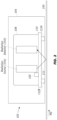
FIG. 2 is a side cross-sectional view of dual scanner heads operating in the transmissive mode; -
FIG. 3 a side cross-sectional view of dual scanner heads operating in the reflective mode; and -
FIG. 4 illustrates a scanner in a web manufacturing or processing system. -
Fig. 1 shows adual scanning system 2 withscanner heads upper scanner head 4 houses asensor device 8 that is supported on abaseplate 10 which has an operative planar surface 11.Actuators lower surface 24 of theupper scanner head 4, are secured tobaseplate 10. Theupper sensor head 4 also houses asensor device 28 that is supported on abaseplate 30.Actuators lower surface 24 of theupper scanner head 4, are secured tobaseplate 30 which has an operativeplanar surface 31. Theupper scanner head 4 is equipped withupper sheet deflectors - The
lower scanner head 6 houses asensor device 14 that is connected to abaseplate 16, which has an operativeplanar surface 17.Actuators upper surface 26 of thelower sensor head 6, are secured tobaseplate 16. Thelower scanner head 6 also houses asensor device 34 that is connected to abaseplate 36 which has an operativeplanar surface 37.Actuators upper surface 26 of thelower scanner head 6, are secured tobaseplate 36. Thelower scanner head 6 is equipped withlower sheet deflectors - The displacement between operative surface 11 of
sensor device 8 andoperative surface 17 ofsensor device 14 define agap 60 and the distance which can measured by displacement measurement means. A suitable apparatus is an inductive-type sensor that has an RF or z-coil 20 which positioned insensor device 8 and measures the distance from z-coil 20 to a reference surface orplate 22 which is thesensor baseplate 16. Inductive-type sensors can particularly suited when the web or sheet being monitored is paper or plastic. The distance ofgap 60 can also be measured by optical displacement, laser-based triangulation, inductive sensors, radar, capacitive sensors, magnetic field-based sensors, microwave radiation-based and acoustic-based sensors. - Similarly, the displacement between
operative surface 31 ofsensor device 28 andoperative surface 37 ofsensor device 34 define agap 62 and the distance can be measured by displacement measurement means. In the case where the sheet product includes a metal substrate, a preferred displacement measurement mechanism includes anelectromagnetic coil 40 which is positioned insensor device 28 and first and secondmagnetic sensors sensor device 34. The two magnetic sensors are preferably in tandem and aligned with the coil along an axis. Theelectromagnetic coil 40 is connected to a source of direct or alternating current (not shown) to generate a magnetic field that is measured by the pair of magnetic sensors, such as fluxgate magnetic sensors. Instead of using an electromagnetic coil and associated driving current, a permanent magnet can be used as the source of magnetic field. This magnetic displacement sensor reads through metal foil materials such as coated metal electrodes and is describedU.S. Pat. No. 11,519,710 to Tixier et al. - Each of the actuators can comprise a multilayer piezoelectric actuator which is in the form of a piezoelectric stack; the stack can be used in conjunction with leverage to increase the actuation distance at the expense of peak force. Piezoelectric actuators can expand or contract upon actuation depending on the applied electric field. Thus, in one application, when the stack is energized, it elongates and pushes the baseplate to which it is secured in a vertical direction that is perpendicular to the associated operative surface. As illustrated in
Fig. 1 , eachscanner head sensor gap -
Fig. 2 shows adual scanning system 72 wherein theupper scanner head 74 houses asensor device 78 that is supported on abaseplate 80 which has operativeplanar surface 81.Actuators lower surface 94 of theupper scanner head 74, are secured tobaseplate 80. Thesensor device 78 includes aradiation source 100. Thelower scanner head 76 houses asensor device 84, which includes aradiation detector 102, that is connected to abaseplate 86 which has operativeplanar surface 87.Actuators upper surface 96 of thelower sensor head 76, are secured tobaseplate 86. The displacement betweensensor device 78 andsensor device 84 is measured with a z-coil 90 and a reference surface orplate 92. - A continuous web or sheet of
material 130 such as paper, plastic, fabric and the like travels through the measurement channel between the upper and lower scanner heads in the machine direction (MD). In one embodiment, theradiation source 100 comprises a nuclear beta source to measure a property, such as the basis weight, of thematerial 130 by measuring the radiation intensity incident on thedetector 102 when thematerial 130 is present as compared to the beta radiation which is incident upon the detector when no material is present. The readings are susceptible to errors if the vertical distance separating theradiation source 100 andradiation detector 102 fluctuate. Depending on the material being monitor, other sources of radiation such as, for instance, x-ray and infrared radiation, can be employed. - With the present invention, a
PID controller 104 receives signals from the gap measurement means 90 and 92 and the controller is configured to transmit gap modulating signals toelectric voltage sources - In the
scanning system 72 ofFig. 2 , both the upper andlower sensor devices sensor devices - It should be noted that with the present invention it is not the vertical position of either scanner heads 74 and 76 that is adjusted with the actuators. The scanning heads (or mounting heads) are typically relatively large structures that house the sensor devices and other components. The sensor devices, such as the radiation source and detectors, are subject to frequency mechanical vibrations typically in the range of 10's to 100' Hz and largely limited to 1 kHz and below. The invention corrects the adverse effects caused by the vibrations by actuating a minimum mass at each sensor. The mass that must be controlled is the minimum mass that impacts the sensing principle being used. For instance, the sensor electronics do not need to be controlled but the radiation source does because the distance of the radiation source to the web affects intensity and therefore the measurement whereas the location of some circuitry does not impact the measurement. The speed of the feedback mechanism must be capable of offsetting these vibrations; this can be achieved with the piezoelectric actuators. The response time of these actuators can be up to 2 orders of magnitude faster than this (single microseconds) for actuation (gap) distances in the tens to hundreds of micrometers.
-
Fig. 3 shows ascanning system 102 wherein the upper scanner (or mounting)head 104 houses asensor device 108 that is supported on abaseplate 110.Actuators upper sensor head 104, are secured tobaseplate 110, which has operativeplanar surface 111. The actuators move thebaseplate 110 in a vertical direction whose axis is perpendicular operativeplanar surface 111. Thesensor device 108 includes aradiation emitter source 154 andreceiver detector 152. - A continuous web or sheet of
material 150 moves pass the upper scanner head in the MD. The displacement betweenoperative surface 111 and the upper surface ofmaterial 150 is measured with alaser triangulation device 120. In one embodiment, theradiation source 154 comprises an infrared radiation source that is focused onto the sheet ofmaterial 150; radiation that is reflected off from the material is captured byradiation detector 152.Actuators operative surface 111 and the upper surface ofmaterial 150. -
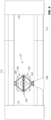
Fig. 4 shows adual scanner 170 in a web manufacturing or processing system. Thescanner 170 travels back and forth along the cross direction, which is perpendicular to the MD direction of the moving web (not shown). Thescanner 170 is driven by a motorized drive mechanism (not shown). Thescanner 170 which includes anupper mounting head 180 and alower mounting head 182 that are mounted on carriages that are supported by upper andlower rails gap 184 through which the web travels. Thesupport structures support structures scanner 170 hassensor devices - The foregoing has described the principles, preferred embodiments and modes of operation of the present invention. However, the invention should not be construed as being limited to the particular embodiments discussed. Thus, the above-described embodiments should be regarded as illustrative rather than restrictive, and it should be appreciated that variations may be made in those embodiments by workers skilled in the art without departing from the scope of the present invention as defined by the following claims.
Claims (15)
- A system for measuring a property of a continuous sheet which has a first side and a second side and which travels in a downstream machine direction that comprises:(a) a first scanner head disposed adjacent to a first side of the sheet, the first scanner head comprising:(i) a first sensor device that has a first movable sensor base that defines a first operative surface facing the first side of the sheet;(ii) a first adjustable actuator configured to move the first sensor base along a first axis;(b) a second scanner head disposed adjacent to the second side of the sheet, the second scanner head comprising a second operative surface facing the second side of the sheet, wherein the first operative surface and the second operative surface define a sensor gap through which the continuous sheet travels;(c) means for measuring the distance of the first sensor gap and generating first signals representative of the measured sensor gap distance; and(d) control means for controlling the first adjustable actuator in response to the first signals to maintain the sensor gap distance at a desired gap distance.
- The system of claim 1 wherein the first sensor device comprises a (i) source radiation that is transmitted toward the continuous sheet and a (ii) detector that is configured to receive reflected radiation.
- The system of claim 1 wherein the first sensor device comprises a source of radiation that is transmitted toward the continuous sheet and the second scanner head comprises a second sensor device that comprises a detector and that defines the second operative surface.
- The system of claim 3 wherein the second sensor device has a second movable sensor base and has a second adjustable actuator configured to move the second sensor device along a second axis, and wherein the control means controls the first adjustable actuator and second adjustable actuator in response to the signals to maintain the sensor gap distance at a desired gap distance.
- The system of claim 4 wherein the second movable sensor base defines the second operative surface.
- The system of claim 3 wherein the source of radiation comprises a nuclear source of beta radiation, an x-ray source, or an IR source.
- The system of claim 1 wherein the first adjustable actuator comprises a piezoelectric actuator.
- The system of claim 1 wherein the first operative surface defines a planar surface and the first axis is perpendicular to the first operative surface.
- The system of claim 1 wherein the first scanner head is aligned with the second scanner head and the first and second heads are configured move back and forth along a cross direction which is perpendicular to the machine direction.
- The system of claim 1 wherein the continuous sheet comprises paper, plastic, metal, or coated metal substrate.
- The system of claim 1 wherein the continuous sheet comprises metal foil or coated metal substrate and the means for measuring the distance of the first sensor gap comprises a magnetic displacement sensor.
- A system for monitoring characteristics of a continuous sheet which has a first side and a second side and which travels in a downstream machine direction that comprises:(a) a first mounting head, which is disposed adjacent to a first exterior surface of the sheet, comprising:(i) a first movable sensor base that defines a first operative surface facing the first exterior surface of the sheet;(ii) a first actuator configured to move the first sensor base along a first axis that is perpendicular to the first operative surface;(b) a second mounting head disposed adjacent to the second exterior of the sheet, the second mounting head comprising a second operative surface facing the second exterior surface of the sheet, wherein the first operative surface and the second operative surface define a sensor gap through which the continuous sheet travels, wherein the first mounting head and the second mounting head are aligned and configured to move in a synchronized fashion in the cross direction, which is perpendicular to the machine direction, and wherein at least one sensor device is mounted in the first mounting head, the second mounting head, or in both;(c) means for measuring the distance of the sensor gap and generating signals representative of the measured sensor gap distance; and(d) control means for controlling the first actuator in response to the signals to maintain the measurement gap distance at a desired gap distance.
- The system of claim 12 wherein the second mounting head comprises a second movable sensor base that defines the second operative surface facing the second exterior of the sheet and a second actuator configured to move the second sensor base along a second axis, and wherein the control means is configured to control the first actuator and second actuator in response to the signals to maintain the measurement gap distance at the desired gap distance.
- In a system for monitoring properties of a continuous traveling web that includes a senor head that has an operative surface that is connected to an actuator for moving the operative surface, a method of controlling the sensor gap between the operative surface and the traveling web that comprises:(a) monitoring the distance between the operative surface and traveling web and generating distance signals indicating a measured sensor gap distance;(b) comparing a measured senor gap distance to a target sensor gap distance; and(c) maneuvering operative surface to adjust the sensor gap distance.
- The method of claim 14 wherein the sensor head comprises a movable sensor base that defines the operative surface facing a first side of the web and an actuator configured to maneuver the sensor base along an axis which is perpendicular to the operative surface, wherein step (c) comprises activating the actuator to maneuver the movable sensor base.
Applications Claiming Priority (1)
| Application Number | Priority Date | Filing Date | Title |
|---|---|---|---|
| US18/212,434 US12601590B2 (en) | 2023-06-21 | 2023-06-21 | Method to control gap for sheet manufacturing measurement processes |
Publications (1)
| Publication Number | Publication Date |
|---|---|
| EP4488618A1 true EP4488618A1 (en) | 2025-01-08 |
Family
ID=91301962
Family Applications (1)
| Application Number | Title | Priority Date | Filing Date |
|---|---|---|---|
| EP24178381.0A Pending EP4488618A1 (en) | 2023-06-21 | 2024-05-28 | Method to control gap for sheet manufacturing measurement processes |
Country Status (6)
| Country | Link |
|---|---|
| US (1) | US12601590B2 (en) |
| EP (1) | EP4488618A1 (en) |
| JP (1) | JP7818649B2 (en) |
| KR (1) | KR20240178209A (en) |
| CN (1) | CN119179340A (en) |
| CA (1) | CA3241701A1 (en) |
Families Citing this family (2)
| Publication number | Priority date | Publication date | Assignee | Title |
|---|---|---|---|---|
| US20230391571A1 (en) * | 2022-06-06 | 2023-12-07 | Honeywell International Inc. | Machine Direction Position Profile Measurement in Sheet Manufacturing Systems |
| US12601590B2 (en) * | 2023-06-21 | 2026-04-14 | Honeywell International Inc. | Method to control gap for sheet manufacturing measurement processes |
Citations (3)
| Publication number | Priority date | Publication date | Assignee | Title |
|---|---|---|---|---|
| US20050157314A1 (en) * | 2003-12-22 | 2005-07-21 | Pekka Typpoe | Measuring device |
| US20160123773A1 (en) * | 2014-11-03 | 2016-05-05 | Honeywell Asca Inc. | Gap and displacement magnetic sensor system for scanner heads in paper machines or other systems |
| US20210262776A1 (en) * | 2020-02-26 | 2021-08-26 | Honeywell Limited | High Accuracy and High Stability Magnetic Displacement Sensor in the Presence of Electromagnetic Interferences |
Family Cites Families (16)
| Publication number | Priority date | Publication date | Assignee | Title |
|---|---|---|---|---|
| US5315124A (en) | 1992-03-20 | 1994-05-24 | Measurex Corporation | Nuclear gauge |
| US5714763A (en) | 1996-03-25 | 1998-02-03 | Measurex Corporation | Method and apparatus for optical alignment of a measuring head in an X-Y plane |
| US6281679B1 (en) * | 1998-12-21 | 2001-08-28 | Honeywell - Measurex | Web thickness measurement system |
| US6361483B1 (en) | 1999-10-22 | 2002-03-26 | Morrison Berkshire, Inc. | System for controlling vibration of a dynamic surface |
| JP2003269946A (en) * | 2002-03-13 | 2003-09-25 | Sigma Koki Kk | Minute displacement device |
| US6967726B2 (en) * | 2003-10-03 | 2005-11-22 | Honeywell International Inc. | Means for in-place automated calibration of optically-based thickness sensor |
| KR100910461B1 (en) | 2006-12-26 | 2009-08-04 | 주식회사 포스코 | Electromagnetic vibration damper for controlling vibration of plated steel sheet through self-tuning PID control |
| JP4853836B2 (en) * | 2007-09-19 | 2012-01-11 | 株式会社安川電機 | Precision fine positioning apparatus and fine positioning stage equipped with the same |
| US8256103B2 (en) * | 2010-03-05 | 2012-09-04 | Asm Assembly Automation Ltd | Actuator for maintaining alignment of die detachment tools |
| DE102010063232A1 (en) * | 2010-12-16 | 2012-06-21 | Voith Patent Gmbh | Apparatus and method for basis weight determination |
| US9121832B2 (en) | 2011-09-01 | 2015-09-01 | Honeywell Asca Inc. | Apparatus and method for reducing vibrations of scanning sensors in web manufacturing or processing systems |
| US9612213B2 (en) | 2014-05-08 | 2017-04-04 | Honeywell Asca Inc. | Automatic z-correction for basis weight sensors |
| US9416492B1 (en) * | 2015-01-28 | 2016-08-16 | Honeywell Limited | System and method for adjusting measurement position of scanning head |
| US11826773B2 (en) * | 2021-03-29 | 2023-11-28 | Honeywell International Inc. | Correlate thermographic image data to online scanning basis weight measurement |
| FI130159B (en) * | 2021-03-31 | 2023-03-22 | Valmet Automation Oy | Measurement apparatus for and method of determining dry stuff content of moving sheet of paper or board |
| US12601590B2 (en) * | 2023-06-21 | 2026-04-14 | Honeywell International Inc. | Method to control gap for sheet manufacturing measurement processes |
-
2023
- 2023-06-21 US US18/212,434 patent/US12601590B2/en active Active
-
2024
- 2024-05-16 CN CN202410611339.9A patent/CN119179340A/en active Pending
- 2024-05-22 JP JP2024083078A patent/JP7818649B2/en active Active
- 2024-05-28 EP EP24178381.0A patent/EP4488618A1/en active Pending
- 2024-06-13 KR KR1020240076664A patent/KR20240178209A/en active Pending
- 2024-06-14 CA CA3241701A patent/CA3241701A1/en active Pending
Patent Citations (4)
| Publication number | Priority date | Publication date | Assignee | Title |
|---|---|---|---|---|
| US20050157314A1 (en) * | 2003-12-22 | 2005-07-21 | Pekka Typpoe | Measuring device |
| US20160123773A1 (en) * | 2014-11-03 | 2016-05-05 | Honeywell Asca Inc. | Gap and displacement magnetic sensor system for scanner heads in paper machines or other systems |
| US20210262776A1 (en) * | 2020-02-26 | 2021-08-26 | Honeywell Limited | High Accuracy and High Stability Magnetic Displacement Sensor in the Presence of Electromagnetic Interferences |
| US11519710B2 (en) | 2020-02-26 | 2022-12-06 | Honeywell Limited | High accuracy and high stability magnetic displacement sensor in the presence of electromagnetic interferences |
Also Published As
| Publication number | Publication date |
|---|---|
| KR20240178209A (en) | 2024-12-30 |
| CA3241701A1 (en) | 2025-06-17 |
| JP2025003327A (en) | 2025-01-09 |
| CN119179340A (en) | 2024-12-24 |
| US12601590B2 (en) | 2026-04-14 |
| US20240426604A1 (en) | 2024-12-26 |
| JP7818649B2 (en) | 2026-02-20 |
Similar Documents
| Publication | Publication Date | Title |
|---|---|---|
| US12601590B2 (en) | Method to control gap for sheet manufacturing measurement processes | |
| CA2356337C (en) | Web caliper measuring system | |
| EP1039262B1 (en) | Sheet thickness and swell measurement method and apparatus therefor | |
| EP3872443B1 (en) | High accuracy and high stability magnetic displacement sensor in the presence of electromagnetic interferences | |
| CA2591885C (en) | Thin film thickness measurement method and apparatus | |
| EP2771647B1 (en) | Scanner belt load and stretch compensation control system | |
| EP0890078B1 (en) | Method and apparatus for optical alignment of a measuring head in an x-y plane | |
| US20070159189A1 (en) | Apparatus and method for evaluating driving characteristics of scanner | |
| US9612213B2 (en) | Automatic z-correction for basis weight sensors | |
| US5569835A (en) | Reference wire compensation method and apparatus | |
| CN111712729A (en) | Scanning Thickness and Basis Weight Sensors for Sheet Products Using Terahertz | |
| US4674882A (en) | Precision optical displacement measuring instrument using servo controlled fiber optic sensor | |
| US3923395A (en) | Process for measuring the distance of and the speed component of an object perpendicular to a reference line | |
| US4711577A (en) | Optical configuration of fiber optic sensor for symmetric dynamic response about the optical null | |
| JP2003254722A (en) | Method and instrument for measuring thickness | |
| JPH05194080A (en) | Apparatus for controlling molten liquid level in cz process and controlling method | |
| US7071480B2 (en) | Sensor with alignment self compensation | |
| JP2008128756A (en) | X-ray thickness measuring device | |
| JP2006266959A (en) | Color measuring device and color measuring method for object surface | |
| JPS6363949A (en) | Measuring apparatus for characteristics of sheetlike object | |
| USRE33078E (en) | Optical configuration of fiber optic sensor for symmetric dynamic response about the optical null | |
| KR20220065241A (en) | Vibration generator with minimal parasitic motion and ripple | |
| JP2000211783A (en) | Method and device for measuring metal strip position | |
| JPH05111768A (en) | Weld line position detector | |
| JPH03266006A (en) | Positioning table drive control method |
Legal Events
| Date | Code | Title | Description |
|---|---|---|---|
| PUAI | Public reference made under article 153(3) epc to a published international application that has entered the european phase |
Free format text: ORIGINAL CODE: 0009012 |
|
| STAA | Information on the status of an ep patent application or granted ep patent |
Free format text: STATUS: REQUEST FOR EXAMINATION WAS MADE |
|
| 17P | Request for examination filed |
Effective date: 20240528 |
|
| AK | Designated contracting states |
Kind code of ref document: A1 Designated state(s): AL AT BE BG CH CY CZ DE DK EE ES FI FR GB GR HR HU IE IS IT LI LT LU LV MC ME MK MT NL NO PL PT RO RS SE SI SK SM TR |