EP4488604A1 - Refrigerator storage system - Google Patents
Refrigerator storage system Download PDFInfo
- Publication number
- EP4488604A1 EP4488604A1 EP24186314.1A EP24186314A EP4488604A1 EP 4488604 A1 EP4488604 A1 EP 4488604A1 EP 24186314 A EP24186314 A EP 24186314A EP 4488604 A1 EP4488604 A1 EP 4488604A1
- Authority
- EP
- European Patent Office
- Prior art keywords
- bin
- secondary container
- container
- engage
- refrigerator
- Prior art date
- Legal status (The legal status is an assumption and is not a legal conclusion. Google has not performed a legal analysis and makes no representation as to the accuracy of the status listed.)
- Pending
Links
Images



Classifications
-
- F—MECHANICAL ENGINEERING; LIGHTING; HEATING; WEAPONS; BLASTING
- F25—REFRIGERATION OR COOLING; COMBINED HEATING AND REFRIGERATION SYSTEMS; HEAT PUMP SYSTEMS; MANUFACTURE OR STORAGE OF ICE; LIQUEFACTION SOLIDIFICATION OF GASES
- F25D—REFRIGERATORS; COLD ROOMS; ICE-BOXES; COOLING OR FREEZING APPARATUS NOT OTHERWISE PROVIDED FOR
- F25D25/00—Charging, supporting, and discharging the articles to be cooled
- F25D25/005—Charging, supporting, and discharging the articles to be cooled using containers
-
- F—MECHANICAL ENGINEERING; LIGHTING; HEATING; WEAPONS; BLASTING
- F25—REFRIGERATION OR COOLING; COMBINED HEATING AND REFRIGERATION SYSTEMS; HEAT PUMP SYSTEMS; MANUFACTURE OR STORAGE OF ICE; LIQUEFACTION SOLIDIFICATION OF GASES
- F25D—REFRIGERATORS; COLD ROOMS; ICE-BOXES; COOLING OR FREEZING APPARATUS NOT OTHERWISE PROVIDED FOR
- F25D23/00—General constructional features
- F25D23/02—Doors; Covers
- F25D23/028—Details
-
- F—MECHANICAL ENGINEERING; LIGHTING; HEATING; WEAPONS; BLASTING
- F25—REFRIGERATION OR COOLING; COMBINED HEATING AND REFRIGERATION SYSTEMS; HEAT PUMP SYSTEMS; MANUFACTURE OR STORAGE OF ICE; LIQUEFACTION SOLIDIFICATION OF GASES
- F25D—REFRIGERATORS; COLD ROOMS; ICE-BOXES; COOLING OR FREEZING APPARATUS NOT OTHERWISE PROVIDED FOR
- F25D23/00—General constructional features
- F25D23/02—Doors; Covers
- F25D23/04—Doors; Covers with special compartments, e.g. butter conditioners
-
- F—MECHANICAL ENGINEERING; LIGHTING; HEATING; WEAPONS; BLASTING
- F25—REFRIGERATION OR COOLING; COMBINED HEATING AND REFRIGERATION SYSTEMS; HEAT PUMP SYSTEMS; MANUFACTURE OR STORAGE OF ICE; LIQUEFACTION SOLIDIFICATION OF GASES
- F25D—REFRIGERATORS; COLD ROOMS; ICE-BOXES; COOLING OR FREEZING APPARATUS NOT OTHERWISE PROVIDED FOR
- F25D25/00—Charging, supporting, and discharging the articles to be cooled
- F25D25/02—Charging, supporting, and discharging the articles to be cooled by shelves
- F25D25/021—Charging, supporting, and discharging the articles to be cooled by shelves combined with trays
-
- F—MECHANICAL ENGINEERING; LIGHTING; HEATING; WEAPONS; BLASTING
- F25—REFRIGERATION OR COOLING; COMBINED HEATING AND REFRIGERATION SYSTEMS; HEAT PUMP SYSTEMS; MANUFACTURE OR STORAGE OF ICE; LIQUEFACTION SOLIDIFICATION OF GASES
- F25D—REFRIGERATORS; COLD ROOMS; ICE-BOXES; COOLING OR FREEZING APPARATUS NOT OTHERWISE PROVIDED FOR
- F25D25/00—Charging, supporting, and discharging the articles to be cooled
- F25D25/02—Charging, supporting, and discharging the articles to be cooled by shelves
- F25D25/024—Slidable shelves
- F25D25/025—Drawers
Definitions
- the present disclosure relates to an appliance such as a refrigerator.
- Refrigerators In order to keep food fresh, a low temperature must be maintained within a refrigerator to reduce the reproduction rate of harmful bacteria.
- Refrigerators circulate refrigerant and change the refrigerant from a liquid state to a gas state by an evaporation process in order cool the air within the refrigerator. During the evaporation process, heat is transferred to the refrigerant. After evaporating, a compressor increases the pressure, and in turn, the temperature of the refrigerant. The gas refrigerant is then condensed into a liquid and the excess heat is rejected to the ambient surroundings. The process then repeats.
- a refrigerator includes a door, a bin, an adapter plate, and a secondary container.
- the door has an interior surface.
- the bin is disposed along the interior surface of the door.
- the bin has a receptacle disposed along a top side of the bin.
- the bin also includes opposing rails disposed below the receptacle along a bottom side of the of the bin.
- a space is defined between the opposing rails.
- the adapter plate is secured to the top side of the bin.
- the adapter plate defines a plurality of orifices configured to receive primary containers.
- the secondary container defines grooves on opposing sides of the secondary container.
- the secondary container is configured to engage the opposing rails within the grooves for inserting and removing the secondary container into and from the space.
- the opposing rails include upward extending protrusions
- the secondary container defines notches extending upward from the grooves
- the upward extending protrusions are configured to engage the secondary container within the notches to secure the position of the secondary container within the space.
- rearward ends of the opposing rails are sloped downward, and the secondary container is configured to engage the rearward ends of the opposing rails such that the secondary container is biased toward a back end of the bin and into the space.
- the bin further comprises a stop disposed along a back end of the bin within the space, and the stop is configured to engage the secondary container to limit travel of the secondary container into the space.
- the bin further comprises a protrusion configured to engage a top of the secondary container to restrict vertical movement of the secondary container within the space.
- the plurality of orifices includes varying-sized orifices
- the primary containers include varying-sized containers
- the varying-sized orifices are configured receive corresponding varying-sized containers.
- a refrigerator door bin system includes a receptacle, rails, an adapter, and a container.
- the rails extend downward from the receptacle.
- the rails define a space below the receptacle.
- the adapter is secured to a top side of the receptacle.
- the adapter defines a plurality of container-receiving openings.
- the container is configured to engage the rails for inserting and removing the container into and from the space.
- the rails include upward extending protrusions, the container defines notches, and the upward extending protrusions are configured to engage the container within the notches to secure the position of the container within the space.
- rearward ends of the rails are sloped downward, and the container is configured to engage the rearward ends of the rails such that the container is biased into the space.
- the refrigerator door bin system further comprises a stop extending downward from the receptacle and into the space, wherein the stop is configured to engage the container to limit travel of the container into the space.
- the refrigerator door bin system further comprises a protrusion extending downward from the receptacle and into the space, wherein the protrusion is configured to engage a top of the container to restrict vertical movement of the container within the space.
- the plurality of container-receiving openings includes varying-sized openings.
- the rails include first and second spaced-apart rails, and the first and second spaced-apart rails at least partially define the space therebetween.
- a refrigerator bin system includes a receptacle, at least one rail, and a secondary container.
- the receptacle has a top side defining a plurality of orifices of varying sizes configured to receive primary containers of varying sizes.
- the at least one rail is disposed below receptacle.
- the secondary container is configured to engage the at least one rail for securing and removing the secondary container onto and from the receptacle.
- the at least one rail includes at least one upward extending protrusion
- the secondary container defines at least one notch
- the at least one upward extending protrusion is configured to engage the secondary container within the at least one notch to secure the position of the secondary container on the receptacle.
- each rail of the at least one rail are sloped downward and the secondary container is configured to engage the rearward ends of each rail of the at least one rail such that the secondary container is biased onto the receptacle.
- the refrigerator bin system further comprises a stop extending downward from the receptacle, where the stop is configured to engage the secondary container to limit travel of the secondary container relative to the receptacle.
- the refrigerator bin system further comprises a protrusion extending downward from the receptacle, wherein the protrusion configured to engage a top of the secondary container to restrict vertical movement of the secondary container relative to the receptacle.
- the at least one rail includes first and second rails.
- the first and second rails define a space therebetween that is configured to receive the secondary container.
- the refrigerator 10 may have a first internal storage chamber, internal cavity, or fresh food compartment 12 configured to refrigerate and not freeze consumables within the fresh food compartment 12, and a second internal storage chamber, internal cavity, or a freezer compartment 14 configured to freeze consumables within the freezer compartment 14 during normal use.
- the refrigerator 10 includes panels or walls 13 that form a housing and define the fresh food compartment 12 and the freezer compartment 14.
- the walls 13 may more specifically form an inner or internal liner of the refrigerator 10.
- the walls 13 may include a rear or back wall, a top wall, a bottom wall, and two side walls.
- the walls 13 may also include additional internal walls, such as a divider wall between the fresh food compartment 12 and freezer compartment 14.
- One or more shelves 15 may be secured to the walls 13 within the fresh food compartment 12.
- One or more drawers 17 may be slidably secured to the shelves 15 or the walls within the fresh food compartment 12. More specifically, the drawers 17 may be slidably secured to the shelves 15 or the walls within the fresh food compartment 12 via tracks or rails.
- One or more of the drawers 17 may be either a pantry drawer 19 or a crisper drawer 21.
- Crisper drawer 21 may more specifically be drawers defining a storage space that is kept at a desired humidity that may be different from the remainder of the fresh food compartment 12, but that is optimal for maintaining freshness of fruits and vegetables.
- the refrigerator 10 may have one or more doors 16, 18 that provide selective access to the interior volume of the refrigerator 10 where consumables may be stored. As shown, the fresh food compartment doors are designated 16, and the freezer door is designated 18. It may also be shown that the fresh food compartment 12 may only have one door 16.
- the doors 16 may be rotatably secured to the walls 13 by one or more hinges.
- the freezer compartment 14 is typically kept at a temperature below the freezing point of water
- the fresh food compartment 12 is typically kept at a temperature above the freezing point of water and generally below a temperature of from about 1.5° C. to about 10° C., more typically below about 3.5° C.
- the doors 16 may each include an exterior panel 20 and an interior panel 22 that is disposed on an internal side of the respective exterior panel 20 of each door 16.
- the interior panels 22 may be configured to face the fresh food compartment 12 when the doors 16 are in closed positions (See Figure 1 ).
- the interior panel 22 may more specifically be a door liner.
- An insulating material, such as an insulating foam, may be disposed between the exterior panel 20 and interior panel 22 of each door 16 in order reduce the heat transfer from the ambient surroundings and increase the efficiency of the refrigerator.
- the refrigerator 10 may also have a water inlet that is fastened to and in fluid communication with a household water supply of potable water.
- the household water supply connects to a municipal water source or a well.
- the water inlet may be fluidly engaged with one or more of a water filter, a water reservoir, and a refrigerator water supply line.
- the refrigerator water supply line may include one or more nozzles and one or more valves.
- the refrigerator water supply line may supply water to one or more water outlets; typically one outlet for water is in the dispensing area and another to an ice tray.
- the refrigerator 10 may also have a control board or controller that sends electrical signals to the one or more valves when prompted by a user that water is desired or if an ice making cycle is required.
- Such a controller may be part of a larger control system and may be controlled by various other controllers throughout the refrigerator 10, and one or more other controllers can collectively be referred to as a "controller” that controls various functions of the refrigerator 10 in response to inputs or signals to control functions of the refrigerator 10.
- the controller may include a microprocessor or central processing unit (CPU) in communication with various types of computer readable storage devices or media.
- Computer readable storage devices or media may include volatile and nonvolatile storage in read-only memory (ROM), random-access memory (RAM), and keep-alive memory (KAM), for example.
- KAM is a persistent or non-volatile memory that may be used to store various operating variables while the CPU is powered down.
- Computer-readable storage devices or media may be implemented using any of a number of known memory devices such as PROMs (programmable read-only memory), EPROMs (electrically PROM), EEPROMs (electrically erasable PROM), flash memory, or any other electric, magnetic, optical, or combination memory devices capable of storing data, some of which represent executable instructions, used by the controller in controlling the refrigerator 10.
- PROMs programmable read-only memory
- EPROMs electrically PROM
- EEPROMs electrically erasable PROM
- flash memory or any other electric, magnetic, optical, or combination memory devices capable of storing data, some of which represent executable instructions, used by the controller in controlling the refrigerator 10.
- Control logic or functions performed by the controller may be represented by flow charts or similar diagrams in one or more figures. These figures provide representative control strategies and/or logic that may be implemented using one or more processing strategies such as eventdriven, interrupt-driven, multi-tasking, multi-threading, and the like. As such, various steps or functions illustrated may be performed in the sequence illustrated, in parallel, or in some cases omitted. Although not always explicitly illustrated, one of ordinary skill in the art will recognize that one or more of the illustrated steps or functions may be repeatedly performed depending upon the particular processing strategy being used. Similarly, the order of processing is not necessarily required to achieve the features and advantages described herein, but is provided for ease of illustration and description.
- the control logic may be implemented primarily in software executed by a microprocessor-based controller.
- control logic may be implemented in software, hardware, or a combination of software and hardware in one or more controllers depending upon the particular application.
- control logic may be provided in one or more computer-readable storage devices or media having stored data representing code or instructions executed by a computer to control the refrigerator 10 or its subsystems.
- the computer-readable storage devices or media may include one or more of a number of known physical devices which utilize electric, magnetic, and/or optical storage to keep executable instructions and associated calibration information, operating variables, and the like.
- the doors 16 may also include storage bins 24 that are able to hold food items or containers.
- the storage bins 24 may be secured to interior surfaces 26 or the interior panels 22 of each door 16.
- the storage bins 24 may integrally formed within or defined by the interior panels 22 of each door 16.
- a portion of the storage bins 24 may be secured to the interior panels 22 of each door 16, while another portion of the storage bins 24 may be integrally formed within or defined by the interior panels 22 of each door 16.
- the storage bins 24 may include shelves (e.g., a lower surface upon, which a food item or container may rest upon) that extend from back and/or side surfaces of the interior panels 22 of each door 16.
- the bin system 28 may be referred to as the refrigerator bin system.
- the bin 28 may be disposed anywhere within the refrigerator 10 (e.g., within the fresh food compartment 12 or the freezer compartment 14).
- the bin system 28 may be secured to one of the panels or walls 13 within the fresh food compartment 12 or the freezer compartment 14.
- the bins system 28 may be secured to one of the doors 16 (e.g., the bin system 28 may be secured to the interior surface 26 or the interior panel 22 of one of the doors 16).
- one or more of the bins 24 illustrated in Figure 3 may be replaced by the bin system 28. If the bin system 28 is secured to one of the doors 26, the bin system 28 may be referred to as the refrigerator door bin system.
- the bin system 28 may be disposed along or secured to the interior surface 26 or the interior panel 22 of one of the doors 16. Alternatively, the bin system 28 may disposed along or secured to one of the panels or walls 13 within the fresh food compartment 12 or the freezer compartment 14.
- the bin system 28 includes a bin 30.
- the bin 30 has a receptacle 32 disposed along a top side 34 of the bin 30.
- the bin 30 also includes at least one rail (hereinafter referred to as rails 36) that are disposed below the receptacle 32 along a bottom side 38 of the of the bin 30.
- the rails 36 extending downward from receptacle 32 and define a space 40 below the receptacle 32.
- the rails 36 may include first and second spaced-apart opposing rails and the space 40 may be at least partially defined between the first and second opposing rails.
- An insert or adapter plate 42 is secured to the top side 34 of the bin 30. More specifically, the adapter plate 42 may be secured to the top side of the receptacle 32.
- the adapter plate 42 defines a plurality of orifices 44 configured to receive primary containers 46.
- the orifices 44 may be referred to as container-receiving openings.
- the plurality of orifices 44 may varying in size, the primary containers 46 may varying in size, and the orifices 44 may be configured to receive primary containers 46 having corresponding sizes.
- the bin 30, or more specifically the receptacle 32 may define the plurality of orifices 44 as opposed to a separate adapter plate 42.
- the depth at which the primary containers 46 extend downward into the adapter plate 42 is designed to be equal to or within a plus or minus 15% variance of the height of the center of mass of the primary containers 46.
- the primary containers 46 have an unfavorable rotational moment about the adapter plate 42, maintaining the position of the primary containers 46 on the bin system 28 as the refrigerator doors 16 open and close.
- the resultant center of masses of the primary containers 46 is below the center of masses of the empty primary containers 46 resulting in an increased favorable condition for the primary containers 46 to remain in place and not rotate out of the adapter plate 42 as the refrigerator doors 16 open and close.
- a secondary container 48 is configured to engage the rails 36 for securing the secondary contain 48 onto the bin 30, or more specifically onto the receptacle 32, and for removing the secondary container 48 from the bin 30, or more specifically from the receptacle 32. More specifically, the secondary container 48 is configured to engage the rails 36 for inserting the secondary container 48 into the space 40 and for removing the secondary container 48 from the space 40.
- the secondary container 48 defines grooves 50 on opposing sides of the secondary container 48.
- the secondary container 48 is configured to engage the rails 36 within the grooves 50 for inserting the secondary container 48 into the space 40 and for removing the secondary container 48 from the space 40.
- the secondary container 48 may include a container portion 52, a lid 54, and a seal 56.
- the seal 56 may be disposed between the lid 54 and the container portion 52.
- the lid 54 may include clips, clamps, or snaps 58 that engage a ridge 60 protruding from an outer periphery of the container portion 52 to secure the lid 54 to the container portion 52. Engagement of the snaps 58 and the ridge 60 may result in the lid 54 compressing the seal 56 and forcing the seal 56 into contact with the container portion 52 such that seal 56 prevents the contents within the secondary container 48 from spilling out of the container portion 52 when the lid 54 is secured to the container portion 52.
- Each primary container 46 may include all of the same subcomponents as the secondary container 48 (e.g., each primary container 46 may include a container portion 47, a lid 49, a seal 51, snaps 53, and a ridge 55) that may function in the same manner as subcomponents the secondary container 48 (e.g., engagement of the snaps 53 and the ridge 55 may result in the lid 49 compressing the seal 51 and forcing the seal 51 into contact with the container portion 47 such that seal 51 prevents the contents within each primary container 46 from spilling out of the container portion 47 when the lid 49 is secured to the container portion 47).
- the rails 36 may include upward at least one upward extending protrusion (hereinafter upward extending protrusions 62).
- the secondary container 48 defines at least one notch (hereinafter notches 64) extending upward from the grooves 50.
- the upward extending protrusions 62 are configured to engage the secondary container 48 within the notches 64 to secure the position of the secondary container 48 on the bin 30, or more specifically on the receptacle 32.
- the upward extending protrusions 62 are configured to engage the secondary container 48 within the notches 64 to secure the position of the secondary container 48 within the space 40.
- Rearward ends 66 of the rails 36 are sloped downward.
- the secondary container 48 may be configured to engage the rearward ends 66 of the rails 36 such that the secondary container 48 is biased onto the bin 30, toward a back end 68 of the bin 30, and into the space 40. More specifically, the secondary container 48 may be configured to engage the rearward ends 66 of the rails 36 such that the secondary container 48 is biased onto the receptacle 32, toward a back end of the receptacle 32, and into the space 40.
- the bin 30 may further comprise a stop 70, or multiple stops 70, disposed along the back end 68 of the bin 30 within the space 40
- the stop 70 is configured to engage the secondary container 48 to limit travel of the secondary container 48 relative to the bin 30 and into the space 40 along direction 72.
- the stop 70 may more specifically extend downward from the receptacle 32 and into the space 40, and may be configured to engage the secondary container 48 to limit travel of the secondary container 48 relative to the receptacle 32 and into the space 40 along direction 72.
- the bin 30 may further comprise a protrusion 74 configured to engage a top of the secondary container 48 to restrict vertical movement of the secondary container 48 (e.g., movement along vertical axis 76) relative to the bin 30 and within the space 40.
- the protrusion 74 may more specifically extend downward from the receptacle 32 and into the space 40, and may be configured to engage top of the secondary container 48 to restrict vertical movement of the secondary container 48 (e.g., movement along vertical axis 76) relative to the receptacle 32 and within the space 40.
- the protrusion may include a ramped section that engages the secondary container 48 to wedge or lodge the secondary container 48 onto the bin 30.
- the protrusion 74 may be integral with the stop 70.
- first, second, third, fourth, etc. for any component, state, or condition described herein may be rearranged in the claims so that they are in chronological order with respect to the claims. Furthermore, it should be understood that any component, state, or condition described herein that does not have a numerical designation may be given a designation of first, second, third, fourth, etc. in the claims if one or more of the specific component, state, or condition are claimed.
Landscapes
- Engineering & Computer Science (AREA)
- Chemical & Material Sciences (AREA)
- Combustion & Propulsion (AREA)
- Physics & Mathematics (AREA)
- Mechanical Engineering (AREA)
- Thermal Sciences (AREA)
- General Engineering & Computer Science (AREA)
- Devices That Are Associated With Refrigeration Equipment (AREA)
- Cold Air Circulating Systems And Constructional Details In Refrigerators (AREA)
Abstract
Description
- The present disclosure relates to an appliance such as a refrigerator.
- In order to keep food fresh, a low temperature must be maintained within a refrigerator to reduce the reproduction rate of harmful bacteria. Refrigerators circulate refrigerant and change the refrigerant from a liquid state to a gas state by an evaporation process in order cool the air within the refrigerator. During the evaporation process, heat is transferred to the refrigerant. After evaporating, a compressor increases the pressure, and in turn, the temperature of the refrigerant. The gas refrigerant is then condensed into a liquid and the excess heat is rejected to the ambient surroundings. The process then repeats.
- A refrigerator includes a door, a bin, an adapter plate, and a secondary container. The door has an interior surface. The bin is disposed along the interior surface of the door. The bin has a receptacle disposed along a top side of the bin. The bin also includes opposing rails disposed below the receptacle along a bottom side of the of the bin. A space is defined between the opposing rails. The adapter plate is secured to the top side of the bin. The adapter plate defines a plurality of orifices configured to receive primary containers. The secondary container defines grooves on opposing sides of the secondary container. The secondary container is configured to engage the opposing rails within the grooves for inserting and removing the secondary container into and from the space.
- In some embodiments, the opposing rails include upward extending protrusions, the secondary container defines notches extending upward from the grooves, and the upward extending protrusions are configured to engage the secondary container within the notches to secure the position of the secondary container within the space.
- According to at least one embodiment, rearward ends of the opposing rails are sloped downward, and the secondary container is configured to engage the rearward ends of the opposing rails such that the secondary container is biased toward a back end of the bin and into the space.
- In at least one embodiment, the bin further comprises a stop disposed along a back end of the bin within the space, and the stop is configured to engage the secondary container to limit travel of the secondary container into the space.
- According to some embodiments, the bin further comprises a protrusion configured to engage a top of the secondary container to restrict vertical movement of the secondary container within the space.
- In some embodiments, the plurality of orifices includes varying-sized orifices, the primary containers include varying-sized containers, and the varying-sized orifices are configured receive corresponding varying-sized containers.
- A refrigerator door bin system includes a receptacle, rails, an adapter, and a container. The rails extend downward from the receptacle. The rails define a space below the receptacle. The adapter is secured to a top side of the receptacle. The adapter defines a plurality of container-receiving openings. The container is configured to engage the rails for inserting and removing the container into and from the space.
- According to at least one embodiment, the rails include upward extending protrusions, the container defines notches, and the upward extending protrusions are configured to engage the container within the notches to secure the position of the container within the space.
- In at least one embodiment, rearward ends of the rails are sloped downward, and the container is configured to engage the rearward ends of the rails such that the container is biased into the space.
- In some embodiments, the refrigerator door bin system further comprises a stop extending downward from the receptacle and into the space, wherein the stop is configured to engage the container to limit travel of the container into the space.
- According to at least one embodiment, the refrigerator door bin system further comprises a protrusion extending downward from the receptacle and into the space, wherein the protrusion is configured to engage a top of the container to restrict vertical movement of the container within the space.
- In at least one embodiment, the plurality of container-receiving openings includes varying-sized openings.
- According to some embodiments, the rails include first and second spaced-apart rails, and the first and second spaced-apart rails at least partially define the space therebetween.
- A refrigerator bin system includes a receptacle, at least one rail, and a secondary container. The receptacle has a top side defining a plurality of orifices of varying sizes configured to receive primary containers of varying sizes. The at least one rail is disposed below receptacle. The secondary container is configured to engage the at least one rail for securing and removing the secondary container onto and from the receptacle.
- In some embodiments, the at least one rail includes at least one upward extending protrusion, the secondary container defines at least one notch, and the at least one upward extending protrusion is configured to engage the secondary container within the at least one notch to secure the position of the secondary container on the receptacle.
- According to at least one embodiment, rearward ends of each rail of the at least one rail are sloped downward and the secondary container is configured to engage the rearward ends of each rail of the at least one rail such that the secondary container is biased onto the receptacle.
- In some embodiments, the refrigerator bin system further comprises a stop extending downward from the receptacle, where the stop is configured to engage the secondary container to limit travel of the secondary container relative to the receptacle.
- In at least one embodiment, the refrigerator bin system further comprises a protrusion extending downward from the receptacle, wherein the protrusion configured to engage a top of the secondary container to restrict vertical movement of the secondary container relative to the receptacle.
- According to some embodiments, the at least one rail includes first and second rails.
- In some embodiments, the first and second rails define a space therebetween that is configured to receive the secondary container.
-
-
Figure 1 is an elevated front view of a French-Door Bottom Mount type refrigerator appliance; -
Figure 2 is an elevated front view of a French-Door Bottom Mount type refrigerator with the refrigerator compartment doors open; -
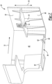
Figure 3 is an isometric view of a bin system for the refrigerator; -
Figure 4 is an exploded view of a portion of the bin system; -
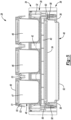
Figure 5 is a cross-sectional view of the bin system taken along line 5-5 inFigure 3 ; -
Figure 6 is an exploded view of a container of the bin system; and -
Figure 7 is a cross-sectional view of a portion of the bin system taken along line 7-7 inFigure 3 . - Embodiments of the present disclosure are described herein. It is to be understood, however, that the disclosed embodiments are merely examples and other embodiments may take various and alternative forms. The figures are not necessarily to scale; some features could be exaggerated or minimized to show details of particular components. Therefore, specific structural and functional details disclosed herein are not to be interpreted as limiting, but merely as a representative basis for teaching one skilled in the art to variously employ the embodiments. As those of ordinary skill in the art will understand, various features illustrated and described with reference to any one of the figures may be combined with features illustrated in one or more other figures to produce embodiments that are not explicitly illustrated or described. The combinations of features illustrated provide representative embodiments for typical applications. Various combinations and modifications of the features consistent with the teachings of this disclosure, however, could be desired for particular applications or implementations.
- Referring to
Figures 1 and 2 , generally arefrigerator 10 of the French-Door Bottom Mount type is illustrated. However, it should be understood that this disclosure could apply to any type of refrigerator, such as a side-by-side, two-door bottom mount, or a top-mount type. As shown inFigures 1 and 2 , therefrigerator 10 may have a first internal storage chamber, internal cavity, orfresh food compartment 12 configured to refrigerate and not freeze consumables within thefresh food compartment 12, and a second internal storage chamber, internal cavity, or afreezer compartment 14 configured to freeze consumables within thefreezer compartment 14 during normal use. Therefrigerator 10 includes panels orwalls 13 that form a housing and define thefresh food compartment 12 and thefreezer compartment 14. Thewalls 13 may more specifically form an inner or internal liner of therefrigerator 10. Thewalls 13 may include a rear or back wall, a top wall, a bottom wall, and two side walls. Thewalls 13 may also include additional internal walls, such as a divider wall between thefresh food compartment 12 andfreezer compartment 14. - One or
more shelves 15 may be secured to thewalls 13 within thefresh food compartment 12. One or more drawers 17 may be slidably secured to theshelves 15 or the walls within thefresh food compartment 12. More specifically, the drawers 17 may be slidably secured to theshelves 15 or the walls within thefresh food compartment 12 via tracks or rails. One or more of the drawers 17 may be either a pantry drawer 19 or a crisper drawer 21. Crisper drawer 21 may more specifically be drawers defining a storage space that is kept at a desired humidity that may be different from the remainder of thefresh food compartment 12, but that is optimal for maintaining freshness of fruits and vegetables. - The
refrigerator 10 may have one ormore doors refrigerator 10 where consumables may be stored. As shown, the fresh food compartment doors are designated 16, and the freezer door is designated 18. It may also be shown that thefresh food compartment 12 may only have onedoor 16. Thedoors 16 may be rotatably secured to thewalls 13 by one or more hinges. - It is generally known that the
freezer compartment 14 is typically kept at a temperature below the freezing point of water, and thefresh food compartment 12 is typically kept at a temperature above the freezing point of water and generally below a temperature of from about 1.5° C. to about 10° C., more typically below about 3.5° C. - The
doors 16 may each include anexterior panel 20 and aninterior panel 22 that is disposed on an internal side of therespective exterior panel 20 of eachdoor 16. Theinterior panels 22 may be configured to face thefresh food compartment 12 when thedoors 16 are in closed positions (SeeFigure 1 ). Theinterior panel 22 may more specifically be a door liner. An insulating material, such as an insulating foam, may be disposed between theexterior panel 20 andinterior panel 22 of eachdoor 16 in order reduce the heat transfer from the ambient surroundings and increase the efficiency of the refrigerator. - The
refrigerator 10 may also have a water inlet that is fastened to and in fluid communication with a household water supply of potable water. Typically, the household water supply connects to a municipal water source or a well. The water inlet may be fluidly engaged with one or more of a water filter, a water reservoir, and a refrigerator water supply line. The refrigerator water supply line may include one or more nozzles and one or more valves. The refrigerator water supply line may supply water to one or more water outlets; typically one outlet for water is in the dispensing area and another to an ice tray. Therefrigerator 10 may also have a control board or controller that sends electrical signals to the one or more valves when prompted by a user that water is desired or if an ice making cycle is required. - Such a controller may be part of a larger control system and may be controlled by various other controllers throughout the
refrigerator 10, and one or more other controllers can collectively be referred to as a "controller" that controls various functions of therefrigerator 10 in response to inputs or signals to control functions of therefrigerator 10. The controller may include a microprocessor or central processing unit (CPU) in communication with various types of computer readable storage devices or media. Computer readable storage devices or media may include volatile and nonvolatile storage in read-only memory (ROM), random-access memory (RAM), and keep-alive memory (KAM), for example. KAM is a persistent or non-volatile memory that may be used to store various operating variables while the CPU is powered down. Computer-readable storage devices or media may be implemented using any of a number of known memory devices such as PROMs (programmable read-only memory), EPROMs (electrically PROM), EEPROMs (electrically erasable PROM), flash memory, or any other electric, magnetic, optical, or combination memory devices capable of storing data, some of which represent executable instructions, used by the controller in controlling therefrigerator 10. - Control logic or functions performed by the controller may be represented by flow charts or similar diagrams in one or more figures. These figures provide representative control strategies and/or logic that may be implemented using one or more processing strategies such as eventdriven, interrupt-driven, multi-tasking, multi-threading, and the like. As such, various steps or functions illustrated may be performed in the sequence illustrated, in parallel, or in some cases omitted. Although not always explicitly illustrated, one of ordinary skill in the art will recognize that one or more of the illustrated steps or functions may be repeatedly performed depending upon the particular processing strategy being used. Similarly, the order of processing is not necessarily required to achieve the features and advantages described herein, but is provided for ease of illustration and description. The control logic may be implemented primarily in software executed by a microprocessor-based controller. Of course, the control logic may be implemented in software, hardware, or a combination of software and hardware in one or more controllers depending upon the particular application. When implemented in software, the control logic may be provided in one or more computer-readable storage devices or media having stored data representing code or instructions executed by a computer to control the
refrigerator 10 or its subsystems. The computer-readable storage devices or media may include one or more of a number of known physical devices which utilize electric, magnetic, and/or optical storage to keep executable instructions and associated calibration information, operating variables, and the like. - The
doors 16 may also includestorage bins 24 that are able to hold food items or containers. Thestorage bins 24 may be secured tointerior surfaces 26 or theinterior panels 22 of eachdoor 16. Alternatively, thestorage bins 24 may integrally formed within or defined by theinterior panels 22 of eachdoor 16. In yet another alternative, a portion of thestorage bins 24 may be secured to theinterior panels 22 of eachdoor 16, while another portion of thestorage bins 24 may be integrally formed within or defined by theinterior panels 22 of eachdoor 16. Thestorage bins 24 may include shelves (e.g., a lower surface upon, which a food item or container may rest upon) that extend from back and/or side surfaces of theinterior panels 22 of eachdoor 16. - Referring to
Figures 3-7 , abin system 28 for therefrigerator 10 is illustrated. Thebin system 28 may be referred to as the refrigerator bin system. Thebin 28 may be disposed anywhere within the refrigerator 10 (e.g., within thefresh food compartment 12 or the freezer compartment 14). Thebin system 28 may be secured to one of the panels orwalls 13 within thefresh food compartment 12 or thefreezer compartment 14. Thebins system 28 may be secured to one of the doors 16 (e.g., thebin system 28 may be secured to theinterior surface 26 or theinterior panel 22 of one of the doors 16). For example, one or more of thebins 24 illustrated inFigure 3 may be replaced by thebin system 28. If thebin system 28 is secured to one of thedoors 26, thebin system 28 may be referred to as the refrigerator door bin system. - The
bin system 28 may be disposed along or secured to theinterior surface 26 or theinterior panel 22 of one of thedoors 16. Alternatively, thebin system 28 may disposed along or secured to one of the panels orwalls 13 within thefresh food compartment 12 or thefreezer compartment 14. Thebin system 28 includes abin 30. Thebin 30 has areceptacle 32 disposed along atop side 34 of thebin 30. Thebin 30 also includes at least one rail (hereinafter referred to as rails 36) that are disposed below thereceptacle 32 along abottom side 38 of the of thebin 30. Therails 36 extending downward fromreceptacle 32 and define aspace 40 below thereceptacle 32. Therails 36 may include first and second spaced-apart opposing rails and thespace 40 may be at least partially defined between the first and second opposing rails. - An insert or
adapter plate 42 is secured to thetop side 34 of thebin 30. More specifically, theadapter plate 42 may be secured to the top side of thereceptacle 32. Theadapter plate 42 defines a plurality oforifices 44 configured to receiveprimary containers 46. Theorifices 44 may be referred to as container-receiving openings. The plurality oforifices 44 may varying in size, theprimary containers 46 may varying in size, and theorifices 44 may be configured to receiveprimary containers 46 having corresponding sizes. Alternatively, thebin 30, or more specifically thereceptacle 32, may define the plurality oforifices 44 as opposed to aseparate adapter plate 42. - The depth at which the
primary containers 46 extend downward into theadapter plate 42 is designed to be equal to or within a plus or minus 15% variance of the height of the center of mass of theprimary containers 46. When the center of mass of eachprimary container 46 is below the top of theadapter plate 42, or very close to the top of the adapter plate 42 (e.g., with the plus or minus 15% variance), theprimary containers 46 have an unfavorable rotational moment about theadapter plate 42, maintaining the position of theprimary containers 46 on thebin system 28 as therefrigerator doors 16 open and close. Furthermore, when theprimary containers 46 are partially filled with food (e.g., below the top of the container), the resultant center of masses of theprimary containers 46 is below the center of masses of the emptyprimary containers 46 resulting in an increased favorable condition for theprimary containers 46 to remain in place and not rotate out of theadapter plate 42 as therefrigerator doors 16 open and close. - A
secondary container 48 is configured to engage therails 36 for securing the secondary contain 48 onto thebin 30, or more specifically onto thereceptacle 32, and for removing thesecondary container 48 from thebin 30, or more specifically from thereceptacle 32. More specifically, thesecondary container 48 is configured to engage therails 36 for inserting thesecondary container 48 into thespace 40 and for removing thesecondary container 48 from thespace 40. Thesecondary container 48 definesgrooves 50 on opposing sides of thesecondary container 48. Thesecondary container 48 is configured to engage therails 36 within thegrooves 50 for inserting thesecondary container 48 into thespace 40 and for removing thesecondary container 48 from thespace 40. - The
secondary container 48 may include acontainer portion 52, alid 54, and aseal 56. Theseal 56 may be disposed between thelid 54 and thecontainer portion 52. Thelid 54 may include clips, clamps, or snaps 58 that engage aridge 60 protruding from an outer periphery of thecontainer portion 52 to secure thelid 54 to thecontainer portion 52. Engagement of thesnaps 58 and theridge 60 may result in thelid 54 compressing theseal 56 and forcing theseal 56 into contact with thecontainer portion 52 such thatseal 56 prevents the contents within thesecondary container 48 from spilling out of thecontainer portion 52 when thelid 54 is secured to thecontainer portion 52. - Each
primary container 46 may include all of the same subcomponents as the secondary container 48 (e.g., eachprimary container 46 may include acontainer portion 47, alid 49, aseal 51, snaps 53, and a ridge 55) that may function in the same manner as subcomponents the secondary container 48 (e.g., engagement of thesnaps 53 and theridge 55 may result in thelid 49 compressing theseal 51 and forcing theseal 51 into contact with thecontainer portion 47 such thatseal 51 prevents the contents within eachprimary container 46 from spilling out of thecontainer portion 47 when thelid 49 is secured to the container portion 47). - The
rails 36 may include upward at least one upward extending protrusion (hereinafter upward extending protrusions 62). Thesecondary container 48 defines at least one notch (hereinafter notches 64) extending upward from thegrooves 50. The upward extendingprotrusions 62 are configured to engage thesecondary container 48 within thenotches 64 to secure the position of thesecondary container 48 on thebin 30, or more specifically on thereceptacle 32. Also, the upward extendingprotrusions 62 are configured to engage thesecondary container 48 within thenotches 64 to secure the position of thesecondary container 48 within thespace 40. - Rearward ends 66 of the
rails 36 are sloped downward. Thesecondary container 48 may be configured to engage the rearward ends 66 of therails 36 such that thesecondary container 48 is biased onto thebin 30, toward aback end 68 of thebin 30, and into thespace 40. More specifically, thesecondary container 48 may be configured to engage the rearward ends 66 of therails 36 such that thesecondary container 48 is biased onto thereceptacle 32, toward a back end of thereceptacle 32, and into thespace 40. - The
bin 30 may further comprise astop 70, ormultiple stops 70, disposed along theback end 68 of thebin 30 within thespace 40 Thestop 70 is configured to engage thesecondary container 48 to limit travel of thesecondary container 48 relative to thebin 30 and into thespace 40 alongdirection 72. Thestop 70 may more specifically extend downward from thereceptacle 32 and into thespace 40, and may be configured to engage thesecondary container 48 to limit travel of thesecondary container 48 relative to thereceptacle 32 and into thespace 40 alongdirection 72. - The
bin 30 may further comprise aprotrusion 74 configured to engage a top of thesecondary container 48 to restrict vertical movement of the secondary container 48 (e.g., movement along vertical axis 76) relative to thebin 30 and within thespace 40. Theprotrusion 74 may more specifically extend downward from thereceptacle 32 and into thespace 40, and may be configured to engage top of thesecondary container 48 to restrict vertical movement of the secondary container 48 (e.g., movement along vertical axis 76) relative to thereceptacle 32 and within thespace 40. The protrusion may include a ramped section that engages thesecondary container 48 to wedge or lodge thesecondary container 48 onto thebin 30. Theprotrusion 74 may be integral with thestop 70. - Engagement between the upward extending
protrusions 62 and thenotches 64, biasing the secondary container toward theback end 68 of thebin 30 via the sloped rearward ends 66 of therails 36, and theprotrusion 74 engaging the top of thesecondary container 48 to restrict vertical movement of thesecondary container 48 operates to lock thesecondary container 48 to thebin 30, or more specifically to thereceptacle 32. Thesecondary container 48 essentially hangs from therails 36. Therefore, the various engagements that operate to lock thesecondary container 48 to thebin 30 prevent the secondary container from dislodging or moving as therefrigerator doors 16 open and close, or in the event therefrigerator doors 16 are slammed. - It should be understood that the designations of first, second, third, fourth, etc. for any component, state, or condition described herein may be rearranged in the claims so that they are in chronological order with respect to the claims. Furthermore, it should be understood that any component, state, or condition described herein that does not have a numerical designation may be given a designation of first, second, third, fourth, etc. in the claims if one or more of the specific component, state, or condition are claimed.
Claims (15)
- A bin system (28) for a refrigerator (10), the bin system (28) comprising:a bin (30);a plurality of primary containers (46); anda secondary container (48);wherein the bin (30) has a top side (34) and a bottom side (38), a receptacle (32) and a space (40) being disposed along the top side (34) and along the bottom side (38), respectively; wherein the receptacle (32) comprises a plurality of orifices (44) configured to receive the primary containers (46); andwherein the bin (30) includes at least one rail (36) configured to interact with the secondary container (48) such that the secondary container (48) engages the at least one rail (36) for securing and removing the secondary container (48) onto and from the space (40).
- The bin system (28) of claim 1, the plurality of primary containers (46) including at least a first primary container and at least a second primary container, wherein the first primary container and second primary container have a first size and a second size, respectively, and wherein the first size is different from the second size.
- The refrigerator bin system (28) of claim 1 or claim 2, the at least one rail (36) including first and second spaced-apart opposing rails (36), wherein the space (40) is configured to receive the secondary container (48) and is at least partly defined between the first and second spaced-apart opposing rails,
optionally wherein the first and second spaced-apart opposing rails are disposed below the receptacle (32). - The bin system (28) of any one of claims 1 to 3, wherein at least one rail (36) includes at least one upward extending protrusion (62) and wherein the secondary container (48) defines at least one notch (64), the at least one upward extending protrusion (62) being configured to engage the secondary container (48) within the at least one notch (64) to secure a position of the secondary container (48) on the space (40).
- The bin system (28) of any one of claims 1 to 4, wherein the at least one rail (36) has a rearward end (66), the rearward end being sloped downward, and wherein the secondary container (48) is configured to engage the rearward end such that the secondary container (48) is biased onto the space (40),
optionally wherein the first and second spaced-apart opposing rails have both rearward ends (66) and the secondary container (48) is configured to engage both rearward ends (66). - The bin system (28) of any one of claims 1 to 5, wherein the bin (30) further comprises at least one stop (70) extending downward from a back end (68) of the bin (30), the at least one stop (70) being configured to engage the secondary container (48) to limit travel of the secondary container (48) relative to the bin (30).
- The bin system (28) of any one of claims 1 to 6, wherein the bin further comprises at least one protrusion (74) extending downward from a bottom surface of the bin (30), the at least one protrusion (74) being configured to engage a top of the secondary container (48) to restrict vertical movement of the secondary container (48) relative to the bin (30),
optionally wherein the at least one protrusion (74) includes a ramped section engaging the secondary container (48) to wedge or lodge the secondary container (48) onto the bin (30). - The bin system (28) of claims 6 and 7, wherein the at least one protrusion (74) is integral with the at least one stop (70).
- The bin system (28) of any one of claims 1 to 8, wherein the secondary container (48) defines grooves (50) on opposing sides of the secondary container (48) and wherein the secondary container (48) is configured to engage the at least one rail (36) within the grooves (50) for inserting and removing the secondary container (48) onto and from the space (40), optionally wherein the at least one rail (36) includes upward extending protrusions (62), the secondary container (48) defines notches (64) extending upward from the grooves (50), and the upward extending protrusions (62) are configured to engage the secondary container (48) within the notches (64) to secure a position the secondary container (48) on the space (40).
- The bin system (28) of any one of claims 1 to 9, wherein the plurality of orifices (44) includes varying-sized orifices (44), the plurality of primary containers (46) includes varying-sized containers (46), and the varying-sized orifices are configured receive corresponding varying-sized containers.
- The bin system (28) of any one of claims 1 to 10, wherein the plurality of orifices (44) are defined by the bin (30).
- The bin system (28) of any one of claims 1 to 10, further comprising an insert or an adapter plate (42), wherein the insert or the adapter plate (42) is separate from the bin (30) and is secured to the top side (34) of the bin (30), wherein the plurality of orifices (44) are defined by the insert or by the adapter plate (42).
- The bin system (28) of claim 12, wherein the primary containers (46) extend downward into the adapter plate (42) at a depth equal to or within a plus or minus 15% variance of the height of the center of mass of the primary containers (46).
- The bin system (28) of any one of claims 1 to 13, wherein at least one of the primary containers (46) and the secondary container (48) includes a container portion (47; 52), a lid (49; 54) and a seal (51; 56), wherein the seal (51; 56) is disposed between the lid (49; 54) and the container portion (47; 52) and wherein the lid (49; 54) include clips, clamps, or snaps (53; 58) that engage a ridge (55; 60) protruding from an outer periphery of the container portion (47; 52) to secure the lid (49; 54) to the container portion (47; 52).
- A refrigerator (10) comprising:a housing forming an inner liner of the refrigerator (10), the housing including walls (13) defining a fresh food compartment (12) configured to store consumables to be refrigerated during normal use of the refrigerator (10) and/or a freezer compartment (14) configured to store consumables to be freezed during normal use of the refrigerator (10);one or more doors (16; 18) configured to provide selective access to the fresh food compartment (12) and/or to the freezer compartment (14), each of the one or more doors (16; 18) including an exterior panel (20) and an interior panel (22), the interior panel (22) being disposed on an internal side of the respective exterior panel (20); andat least one bin system (28) within the fresh food compartment (12) or the freezer compartment (14), the at least one bin system being according to of any one of claims 1 to 14, wherein the at least one bin system (28) is secured to one of the walls (13) of the housing or to the interior panel (22) of one of the doors (16; 18).
Applications Claiming Priority (1)
| Application Number | Priority Date | Filing Date | Title |
|---|---|---|---|
| US18/347,358 US12429277B2 (en) | 2023-07-05 | 2023-07-05 | Refrigerator storage system |
Publications (1)
| Publication Number | Publication Date |
|---|---|
| EP4488604A1 true EP4488604A1 (en) | 2025-01-08 |
Family
ID=91810260
Family Applications (1)
| Application Number | Title | Priority Date | Filing Date |
|---|---|---|---|
| EP24186314.1A Pending EP4488604A1 (en) | 2023-07-05 | 2024-07-03 | Refrigerator storage system |
Country Status (2)
| Country | Link |
|---|---|
| US (2) | US12429277B2 (en) |
| EP (1) | EP4488604A1 (en) |
Citations (6)
| Publication number | Priority date | Publication date | Assignee | Title |
|---|---|---|---|---|
| US5346299A (en) * | 1993-07-15 | 1994-09-13 | General Electric Company | Refrigerator door module mounting assembly |
| US6793096B1 (en) * | 2003-04-08 | 2004-09-21 | Hana Cobi Co., Ltd. | Food item receiving container |
| CN102506555A (en) * | 2011-11-09 | 2012-06-20 | 合肥美的荣事达电冰箱有限公司 | Bottle holder and refrigerator with same |
| DE102016006219A1 (en) * | 2016-03-23 | 2017-09-28 | Liebherr-Hausgeräte Ochsenhausen GmbH | egg tray |
| DE102020102879A1 (en) * | 2019-11-04 | 2021-05-06 | Liebherr-Hausgeräte Ochsenhausen GmbH | Receiving facility |
| WO2023048362A1 (en) * | 2021-09-24 | 2023-03-30 | 삼성전자주식회사 | Refrigerator |
Family Cites Families (26)
| Publication number | Priority date | Publication date | Assignee | Title |
|---|---|---|---|---|
| US3473345A (en) * | 1967-12-26 | 1969-10-21 | Amana Refrigeration Inc | Meat keeper for refrigerators |
| US5820239A (en) * | 1997-06-04 | 1998-10-13 | Maytag Corporation | Storage bin supporting system |
| US6565169B1 (en) * | 2000-11-03 | 2003-05-20 | Comercial Acros Whirpool, S.A. De C.V. | Double crisper drawer for a refrigerator |
| US7472974B2 (en) * | 2005-05-06 | 2009-01-06 | Whirlpool Corporation | Refrigerator with storage bin |
| DE102009028418A1 (en) * | 2009-08-10 | 2011-02-17 | BSH Bosch und Siemens Hausgeräte GmbH | Refrigeration device i.e. household refrigeration apparatus, has moving arrangement comprising frame, box shaped container guided in frame on rails that are uniformly curved upwards, and rib comprising gap at front end |
| TR201106341A1 (en) * | 2011-06-27 | 2013-01-21 | Ar�El�K Anon�M ��Rket� | A cooler containing an ice container placed on the door. |
| TR201106327A1 (en) | 2011-06-27 | 2013-01-21 | Arçeli̇k Anoni̇m Şi̇rketi̇ | A cooler comprising a movable carrier. |
| CN202195645U (en) * | 2011-07-18 | 2012-04-18 | 海信容声(广东)冰箱有限公司 | Multilayer egg rack |
| US20130119846A1 (en) * | 2011-11-15 | 2013-05-16 | Woonkyu Seo | Refrigerator |
| KR20130098623A (en) * | 2012-02-28 | 2013-09-05 | 삼성전자주식회사 | Storage unit and refrigerator having the same |
| US9353989B2 (en) | 2013-10-12 | 2016-05-31 | Melody Ann Furr | Food storage system and method |
| BR102013027044A2 (en) | 2013-10-21 | 2015-08-25 | Whirlpool S.A. | Swiveling Home Appliances Shelf Module |
| DE102014106880A1 (en) | 2014-05-15 | 2015-11-19 | Miele & Cie. Kg | cooling unit |
| CN105466133A (en) * | 2014-08-28 | 2016-04-06 | 博西华电器(江苏)有限公司 | Refrigerator and telescopic egg rack assembly for refrigerator |
| US20160153704A1 (en) * | 2014-12-02 | 2016-06-02 | Whirlpool Corporation | Multi-level drawer organization system for a refrigerating appliance |
| KR102373219B1 (en) * | 2015-12-10 | 2022-03-17 | 삼성전자주식회사 | Refrigerator |
| KR102485709B1 (en) * | 2016-05-31 | 2023-01-09 | 삼성전자주식회사 | Refrigerator |
| CN108131890B (en) * | 2016-12-01 | 2021-06-08 | 东芝生活电器株式会社 | Rotary storage mechanism for refrigerator |
| WO2020207776A1 (en) | 2019-04-09 | 2020-10-15 | Arcelik Anonim Sirketi | An egg tray used as a bottle holder |
| US11268750B1 (en) * | 2020-12-23 | 2022-03-08 | Electrolux Home Products, Inc. | On door drawer and refrigerating appliance with same |
| US11927388B2 (en) * | 2021-07-20 | 2024-03-12 | Electrolux Home Products, Inc. | Reversible drawer assembly |
| EP4325147A4 (en) * | 2021-09-24 | 2024-09-18 | Samsung Electronics Co., Ltd. | REFRIGERATOR |
| CN118076847A (en) * | 2021-12-29 | 2024-05-24 | 三星电子株式会社 | refrigerator |
| EP4394292A4 (en) * | 2022-02-10 | 2025-03-05 | Samsung Electronics Co., Ltd. | Refrigerator |
| TR2022001906A1 (en) * | 2022-02-14 | 2023-08-21 | Bsh Ev Aletleri Sanayi Ve Ticaret Anonim Sirketi | A SHELF ASSEMBLY FOR A COOLING DEVICE |
| CN218349042U (en) * | 2022-10-25 | 2023-01-20 | 浙江哲商工业产品设计有限公司 | Kitchen storage rack |
-
2023
- 2023-07-05 US US18/347,358 patent/US12429277B2/en active Active
-
2024
- 2024-07-03 EP EP24186314.1A patent/EP4488604A1/en active Pending
-
2025
- 2025-08-22 US US19/307,472 patent/US20250389476A1/en active Pending
Patent Citations (6)
| Publication number | Priority date | Publication date | Assignee | Title |
|---|---|---|---|---|
| US5346299A (en) * | 1993-07-15 | 1994-09-13 | General Electric Company | Refrigerator door module mounting assembly |
| US6793096B1 (en) * | 2003-04-08 | 2004-09-21 | Hana Cobi Co., Ltd. | Food item receiving container |
| CN102506555A (en) * | 2011-11-09 | 2012-06-20 | 合肥美的荣事达电冰箱有限公司 | Bottle holder and refrigerator with same |
| DE102016006219A1 (en) * | 2016-03-23 | 2017-09-28 | Liebherr-Hausgeräte Ochsenhausen GmbH | egg tray |
| DE102020102879A1 (en) * | 2019-11-04 | 2021-05-06 | Liebherr-Hausgeräte Ochsenhausen GmbH | Receiving facility |
| WO2023048362A1 (en) * | 2021-09-24 | 2023-03-30 | 삼성전자주식회사 | Refrigerator |
Also Published As
| Publication number | Publication date |
|---|---|
| US20250389476A1 (en) | 2025-12-25 |
| US12429277B2 (en) | 2025-09-30 |
| US20250012506A1 (en) | 2025-01-09 |
Similar Documents
| Publication | Publication Date | Title |
|---|---|---|
| EP4082395A1 (en) | Refrigerator and shelving system for a refrigerator | |
| US10041723B2 (en) | Refrigerator | |
| EP4343242A1 (en) | Refrigerator with a water storage tank | |
| US12429277B2 (en) | Refrigerator storage system | |
| US11460241B1 (en) | Refrigerator and shelving system for a refrigerator | |
| US20240271862A1 (en) | Refrigerator and shelving system for a refrigerator | |
| EP4242564A1 (en) | Refrigerator and storage system for a refrigerator | |
| US11573047B2 (en) | Refrigerator appliance | |
| EP4361539A1 (en) | Refrigerator and mullion for a refrigerator | |
| US20250362074A1 (en) | Bin storage system for a refrigerator appliance | |
| US11920851B2 (en) | Refrigerator appliance | |
| US20260043604A1 (en) | Refrigerator and storage system for a refrigerator | |
| US11549743B1 (en) | Refrigerator appliance | |
| US20250389475A1 (en) | Refrigerator and storage system for a refrigerator | |
| US20260049756A1 (en) | Refrigerator and storage system for a refrigerator | |
| BR102024013216A2 (en) | REFRIGERATOR STORAGE SYSTEM | |
| US12320578B2 (en) | Refrigerator and corresponding shelving system | |
| US11441835B1 (en) | Refrigerator appliance and containment system for contents of refrigerator appliance | |
| US12181208B2 (en) | Refrigerator appliance subcomponent mounting system | |
| US20230408183A1 (en) | Shelving system for a refrigerator | |
| US12281838B2 (en) | Refrigerator appliance | |
| US11480386B2 (en) | Refrigerator and shelving system for a refrigerator | |
| US20260029188A1 (en) | Refrigerator appliance | |
| US20230228479A1 (en) | Refrigerator appliance | |
| US12492859B2 (en) | Refrigerator appliance subcomponent mounting system |
Legal Events
| Date | Code | Title | Description |
|---|---|---|---|
| PUAI | Public reference made under article 153(3) epc to a published international application that has entered the european phase |
Free format text: ORIGINAL CODE: 0009012 |
|
| STAA | Information on the status of an ep patent application or granted ep patent |
Free format text: STATUS: THE APPLICATION HAS BEEN PUBLISHED |
|
| AK | Designated contracting states |
Kind code of ref document: A1 Designated state(s): AL AT BE BG CH CY CZ DE DK EE ES FI FR GB GR HR HU IE IS IT LI LT LU LV MC ME MK MT NL NO PL PT RO RS SE SI SK SM TR |
|
| P01 | Opt-out of the competence of the unified patent court (upc) registered |
Free format text: CASE NUMBER: APP_13280/2025 Effective date: 20250318 |
|
| STAA | Information on the status of an ep patent application or granted ep patent |
Free format text: STATUS: REQUEST FOR EXAMINATION WAS MADE |
|
| 17P | Request for examination filed |
Effective date: 20250605 |