EP4488592A1 - Heat pump cycle device - Google Patents
Heat pump cycle device Download PDFInfo
- Publication number
- EP4488592A1 EP4488592A1 EP23760193.5A EP23760193A EP4488592A1 EP 4488592 A1 EP4488592 A1 EP 4488592A1 EP 23760193 A EP23760193 A EP 23760193A EP 4488592 A1 EP4488592 A1 EP 4488592A1
- Authority
- EP
- European Patent Office
- Prior art keywords
- surface panel
- housing
- handle portion
- outdoor machine
- disposed
- Prior art date
- Legal status (The legal status is an assumption and is not a legal conclusion. Google has not performed a legal analysis and makes no representation as to the accuracy of the status listed.)
- Pending
Links
Images




Classifications
-
- F—MECHANICAL ENGINEERING; LIGHTING; HEATING; WEAPONS; BLASTING
- F24—HEATING; RANGES; VENTILATING
- F24F—AIR-CONDITIONING; AIR-HUMIDIFICATION; VENTILATION; USE OF AIR CURRENTS FOR SCREENING
- F24F1/00—Room units for air-conditioning, e.g. separate or self-contained units or units receiving primary air from a central station
- F24F1/06—Separate outdoor units, e.g. outdoor unit to be linked to a separate room comprising a compressor and a heat exchanger
- F24F1/56—Casing or covers of separate outdoor units, e.g. fan guards
-
- F—MECHANICAL ENGINEERING; LIGHTING; HEATING; WEAPONS; BLASTING
- F24—HEATING; RANGES; VENTILATING
- F24F—AIR-CONDITIONING; AIR-HUMIDIFICATION; VENTILATION; USE OF AIR CURRENTS FOR SCREENING
- F24F1/00—Room units for air-conditioning, e.g. separate or self-contained units or units receiving primary air from a central station
- F24F1/02—Self-contained room units for air-conditioning, i.e. with all apparatus for treatment installed in a common casing
- F24F1/04—Arrangements for portability
-
- F—MECHANICAL ENGINEERING; LIGHTING; HEATING; WEAPONS; BLASTING
- F24—HEATING; RANGES; VENTILATING
- F24F—AIR-CONDITIONING; AIR-HUMIDIFICATION; VENTILATION; USE OF AIR CURRENTS FOR SCREENING
- F24F1/00—Room units for air-conditioning, e.g. separate or self-contained units or units receiving primary air from a central station
- F24F1/06—Separate outdoor units, e.g. outdoor unit to be linked to a separate room comprising a compressor and a heat exchanger
- F24F1/46—Component arrangements in separate outdoor units
- F24F1/48—Component arrangements in separate outdoor units characterised by air airflow, e.g. inlet or outlet airflow
-
- F—MECHANICAL ENGINEERING; LIGHTING; HEATING; WEAPONS; BLASTING
- F24—HEATING; RANGES; VENTILATING
- F24F—AIR-CONDITIONING; AIR-HUMIDIFICATION; VENTILATION; USE OF AIR CURRENTS FOR SCREENING
- F24F1/00—Room units for air-conditioning, e.g. separate or self-contained units or units receiving primary air from a central station
- F24F1/06—Separate outdoor units, e.g. outdoor unit to be linked to a separate room comprising a compressor and a heat exchanger
- F24F1/56—Casing or covers of separate outdoor units, e.g. fan guards
- F24F1/58—Separate protective covers for outdoor units, e.g. solar guards, snow shields or camouflage
-
- F—MECHANICAL ENGINEERING; LIGHTING; HEATING; WEAPONS; BLASTING
- F24—HEATING; RANGES; VENTILATING
- F24F—AIR-CONDITIONING; AIR-HUMIDIFICATION; VENTILATION; USE OF AIR CURRENTS FOR SCREENING
- F24F2221/00—Details or features not otherwise provided for
- F24F2221/12—Details or features not otherwise provided for transportable
Definitions
- the present invention relates to a heat pump cycle apparatus having an outdoor machine in which a handle portion for transportation and installation is included in a housing.
- an outdoor machine used in a heat pump cycle apparatus includes a compressor that compresses a refrigerant, a heat exchanger that performs heat exchange between the refrigerant and air, a fan that blows air to the heat exchanger, and the like, and these devices are housed in a housing.
- the compressor and the heat exchanger increase in size as the air-conditioning capacity increases, and thus the outdoor machine itself tends to be large and heavy.
- Patent Literature 1 a technique in which a plurality of handle portions for holding the outdoor machine is provided around a housing of the outdoor machine, thereby enabling a plurality of workers (for example, two workers) to transport and install the outdoor machine which is a large and heavy object (for example, refer to Patent Literature 1).
- a side on which a blowout port for blowing out air to the outside of the housing is formed is defined as a front surface of the housing
- handle portions are each provided on the front surface, a rear surface, and a left side surface of the housing.
- Patent Literature 1 JP 2019-143952 A
- An outdoor machine has a different weight balance depending on the arrangement of circuit components such as a compressor and a heat exchanger which are housed inside a housing. Therefore, in a top view of the outdoor machine, the position of the center of gravity of the outdoor machine may deviate from the center of the housing. When the position of the center of gravity is deviated, there is a problem in that, during the work of transporting and installing the outdoor machine, the force received by a worker from each handle portion varies depending on the arrangement of handle portions, so that the balance is lost and the work becomes difficult.
- the disclosed technique has been made in view of the above, and an object of the disclosed technique is to provide a heat pump cycle apparatus having an arrangement of a handle portion that facilitates transportation and installation work of an outdoor machine.
- a heat pump cycle apparatus includes an outdoor machine having a housing that houses a heat exchanger therein, wherein the housing is provided with at least three handle portions for transporting the outdoor machine, and the handle portions are provided at positions wherea center of gravity of the outdoor machine is present in an area formed by connecting the handle portions adjacent to each other when the housing is viewed from an upper surface.
- One aspect of the heat pump cycle apparatus disclosed in the present application can provide an outdoor machine having a handle portion that facilitates transportation and installation work of the outdoor machine.
- FIG. 1 is a circuit configuration diagram illustrating an example of a refrigerant circuit and a water circuit of a heat pump cycle apparatus according to the present embodiment.
- the heat pump cycle apparatus 1 includes an outdoor machine 2 and an indoor machine 3, and the outdoor machine 2 and the indoor machine 3 are connected to each other by a water pipe to form a water circuit 4.
- the heat pump cycle apparatus 1 performs cooling or heating of a room (space) in which the indoor machine 3 is disposed by circulating cold water or hot water in the water circuit 4 of the outdoor machine 2 and the indoor machine 3.
- the heat pump cycle apparatus 1 illustrated in FIG. 1 includes one indoor machine 3, the heat pump cycle apparatus may include a plurality of indoor machines 3 connected in parallel to the outdoor machine 2.
- the outdoor machine 2 has a compressor 11, a four-way valve 12, an outdoor heat exchanger (heat exchanger) 13, an outdoor expansion valve 14, a water-refrigerant heat exchanger 15, an accumulator 16, and an outdoor fan (fan) 17.
- the compressor 11, the four-way valve 12, the outdoor heat exchanger 13, the outdoor expansion valve 14, the water-refrigerant heat exchanger 15, and the accumulator 16 are connected to each other by a refrigerant pipe 18 to form a refrigerant circuit 10.
- the refrigerant circuit 10 is completed inside the outdoor machine 2 to constitute a refrigeration cycle.
- a water pipe 19 is connected to the water-refrigerant heat exchanger 15.
- the water pipe 19 extends to the outside of the outdoor machine 2 and is connected to an indoor unit 23 (described later) of the indoor machine 3 to form the water circuit 4.
- the compressor 11 is, for example, a capability variable compressor of a high-pressure container type capable of changing an operation capacity, and compresses a sucked low-pressure gas refrigerant to discharge a high-pressure gas refrigerant.
- the four-way valve 12 is connected to a refrigerant discharge side of the compressor 11, and the accumulator 16 is connected to a refrigerant suction side of the compressor.
- the four-way valve 12 is a valve for switching the direction in which the refrigerant flows in the refrigerant circuit 10, and include a first port 12A to a fourth port 12D.
- the first port 12A is connected to the refrigerant discharge side of the compressor 11.
- the second port 12B is connected to one refrigerant inlet/outlet 13A of the outdoor heat exchanger 13.
- the third port 12C is connected to the refrigerant inflow side of the accumulator 16.
- the fourth port 12D is connected to one refrigerant inlet/outlet 15A of the water-refrigerant heat exchanger 15.
- the outdoor heat exchanger 13 for example, a fin-tube heat exchanger is used.
- the outdoor heat exchanger 13 exchanges heat between a refrigerant and the outside air taken into the outdoor machine 2 by the rotation of the outdoor fan 17.
- the other refrigerant inlet/outlet 13B of the outdoor heat exchanger 13 is connected to the other refrigerant inlet/outlet 15B of the water-refrigerant heat exchanger 15 via the outdoor expansion valve 14.
- the outdoor heat exchanger 13 functions as a condenser when the heat pump cycle apparatus 1 performs cooling operation, to condense (liquefy) the gas refrigerant.
- the outdoor heat exchanger 13 functions as an evaporator when the heat pump cycle apparatus 1 performs heating operation, to evaporate (vaporize) the liquid refrigerant.
- the outdoor expansion valve 14 is provided between the other refrigerant inlet/outlet 13B of the outdoor heat exchanger 13 and the other refrigerant inlet/outlet 15B of the water-refrigerant heat exchanger 15.
- the outdoor expansion valve 14 is, for example, an electronic expansion valve, and decompresses (expands) the liquid refrigerant passing through the outdoor expansion valve 14 by adjusting the valve opening degree.
- the water-refrigerant heat exchanger 15 exchanges heat between the refrigerant circulating in the refrigerant circuit 10 and the water circulating in the water circuit 4.
- the water-refrigerant heat exchanger 15 functions as an evaporator when the heat pump cycle apparatus 1 performs cooling operation or defrosting operation, to evaporate (vaporize) the liquid refrigerant.
- the water-refrigerant heat exchanger 15 functions as a condenser when the heat pump cycle apparatus 1 performs heating operation, to condense (liquefy) the gas refrigerant.
- the water-refrigerant heat exchanger 15 has a water inlet 15C and a water outlet 15D, and the water pipe 19 is connected to each of the water inlet 15C and the water outlet 15D to constitute a part of the water circuit 4.
- a circulation pump 21 for circulating water in the water circuit 4 is provided on the water inlet 15C side
- an air vent valve 22 for venting air entering the water circuit 4 is provided on the water outlet 15D side.
- the refrigerant inflow side of the accumulator 16 is connected to the third port 12C of the four-way valve 12, and the refrigerant outflow side of the accumulator is connected to the refrigerant inflow side of the compressor 11.
- the accumulator 16 is formed as a hollow high-pressure container, separates the refrigerant flowing into the inside thereof into a gas refrigerant and a liquid refrigerant, and causes only the gas refrigerant to be sucked into the compressor 11.
- the outdoor fan 17 is disposed near the outdoor heat exchanger 13 and blows air toward the outdoor heat exchanger 13. Specifically, the outdoor fan 17 takes the outside air into the outdoor machine 2 from a suction port 44, which will be described later, of the outdoor machine 2 and discharges the outside air heat-exchanged with the refrigerant in the outdoor heat exchanger 13 to the outside of the outdoor machine 2 from a blowout port 41, which will be described later.
- the indoor machine 3 has an indoor unit 23.
- the indoor unit 23 for example, a floor heating device or a radiator is used.
- One refrigerant inlet/outlet 23A of the indoor unit 23 is connected to the water outlet 15D of the water-refrigerant heat exchanger 15.
- the other refrigerant inlet/outlet 23B of the indoor unit 23 is connected to the water inlet 15C of the water-refrigerant heat exchanger 15 via the circulation pump 21.
- the indoor unit 23 is connected to the water-refrigerant heat exchanger 15 by the water pipe 19 to constitute the water circuit 4, and the water circulating in the water circuit 4 dissipates or absorbs heat in the indoor unit 23, thereby heating or cooling the air-conditioned space in which the indoor machine 3 is installed.
- the four-way valve 12 is switched so that the first port 12A communicates with the fourth port 12D and the second port 12B communicates with the third port 12C.
- the refrigerant circuit 10 enters a heating cycle in which the water-refrigerant heat exchanger 15 functions as a condenser and the outdoor heat exchanger 13 functions as an evaporator.
- the refrigerant discharged from the compressor 11 flows into the four-way valve 12, and flows from the four-way valve 12 into the water-refrigerant heat exchanger 15.
- the high-temperature gas refrigerant flowing into the water-refrigerant heat exchanger 15 is condensed by exchanging heat with the water circulating in the water circuit 4 of the water-refrigerant heat exchanger 15 by the movement of the circulation pump 21.
- the water circulating in the water circuit 4 is heated by the refrigerant in the water-refrigerant heat exchanger 15 to become hot water.
- the hot water flows into the indoor unit 23 of the indoor machine 3 through the water pipe 19 of the water circuit 4.
- the hot water then dissipates heat in the indoor unit 23, thereby heating the room in which the indoor machine 3 is installed.
- the liquid refrigerant heat-exchanged with water and condensed in the water-refrigerant heat exchanger 15 is decompressed while passing through the outdoor expansion valve 14, and then flows into the outdoor heat exchanger 13.
- the refrigerant flowing into the outdoor heat exchanger 13 exchanges heat with the outside air flowing into the outdoor machine 2 by the rotation of the outdoor fan 17 and evaporates.
- the gas refrigerant evaporated in the outdoor heat exchanger 13 passes through the four-way valve 12 and the accumulator 16 in this order, and is sucked into the compressor 11 and compressed again.
- the four-way valve 12 is switched so that the first port 12A communicates with the second port 12B and the third port 12C communicates with the fourth port 12D.
- the refrigerant circuit 10 enters a cooling cycle in which the water-refrigerant heat exchanger 15 functions as an evaporator and the outdoor heat exchanger 13 functions as a condenser.
- the compressor 11 When the compressor 11 is driven in the above-described state of the refrigerant circuit 10, the refrigerant discharged from the compressor 11 flows into the four-way valve 12, and flows from the four-way valve 12 into the outdoor heat exchanger 13.
- the high-temperature gas refrigerant flowing into the outdoor heat exchanger 13 is condensed by exchanging heat with the outdoor air taken into the outdoor machine 2 by the rotation of the outdoor fan 17. Note that, when the defrosting operation is performed, the frost generated in the outdoor heat exchanger 13 is melted by the heat of the refrigerant flowing into the outdoor heat exchanger 13.
- the liquid refrigerant condensed in the outdoor heat exchanger 13 is decompressed while passing through the outdoor expansion valve 14, and then flows into the water-refrigerant heat exchanger 15.
- the liquid refrigerant flowing into the water-refrigerant heat exchanger 15 is evaporated by exchanging heat with the water circulating in the water circuit 4 of the water-refrigerant heat exchanger 15 by the operation of the circulation pump 21.
- the water circulating in the water circuit 4 is cooled by the refrigerant in the water-refrigerant heat exchanger 15 to become cold water.
- the cold water flows into the indoor unit 23 of the indoor machine 3 through the water pipe 19 of the water circuit 4.
- the cold water then absorbs heat from the indoor air in the indoor unit 23, thereby cooling the room in which the indoor machine 3 is installed. Note that, when the defrosting operation is performed, the circulation of water in the water circuit 4 is stopped by stopping the circulation pump 21 in order to suppress a decrease in the indoor temperature.
- the gas refrigerant evaporated in the water-refrigerant heat exchanger 15 passes through the four-way valve 12 and the accumulator 16 in this order, and is sucked into the compressor 11 and compressed again.
- FIG. 2 is an external perspective view of the outdoor machine as viewed from the front surface side
- FIG. 3 is an external perspective view of the outdoor machine as viewed from the rear surface side
- FIG. 4 is a perspective view illustrating the internal structure of the outdoor machine. Note that directions such as front and rear, up and down, and left and right described below indicate directions when the outdoor machine 2 is viewed from the front surface side in a state in which the outdoor machine 2 is installed, with a direction in which air is blown out from the blowout port 41, which will be described later, as the front.
- the outdoor machine 2 includes a housing 30 having a rectangular parallelepiped box shape in which the dimension in the left-right direction (width direction) is larger than the dimension in the front-rear direction (depth direction).
- the housing 30 includes a bottom plate (bottom surface panel) 31 disposed so as to face the installation surface, a top surface panel 32 disposed above the bottom plate 31 in the height direction, and a side surface panel portion 33 that connects the bottom plate 31 and the top surface panel 32 and partitions the inside and the outside of the housing 30.
- the inside of the housing 30 is divided into a heat exchange chamber RA and a machine chamber RB by a partition plate 34 erected on the bottom plate 31.
- the outdoor heat exchanger 13 is disposed on the rear surface side of the heat exchange chamber RA, and the outdoor fan 17 is disposed on the front surface side.
- the outdoor heat exchanger 13 is formed by being bent in an L-shape when viewed from the upper surface (the top surface panel 32 side), and is supported by the bottom plate 31 along the left side surface side from the rear surface side of the heat exchange chamber RA.
- the outdoor fan 17 is attached to a pair of support members 35, 35 erected on the bottom plate 31.
- the outdoor fan 17 is a so-called axial-flow fan, and draws outside air into the heat exchange chamber RA from the outside of the outdoor machine 2, that is, from the suction port 44 (described later) formed on the rear surface side of the outdoor heat exchanger 13 and a suction opening 46 (described later) formed on the left side surface side, by rotational driving of the outdoor fan 17 by a fan motor not illustrated. Then, the air heat-exchanged with the refrigerant in the outdoor heat exchanger 13 is blown out forward from the blowout port 41 (described later) formed on the front surface side of the heat exchange chamber RA.
- the outdoor machine 2 is a front blowout type outdoor machine that blows out the heat-exchanged air from the front surface side.
- circuit components such as the compressor 11, the accumulator 16, the four-way valve 12 ( FIG. 1 ), and the outdoor expansion valve 14 ( FIG. 1 ) that constitute a part of the refrigerant circuit 10 are disposed, and the circuit components are connected to each other by the refrigerant pipe 18.
- the compressor 11 and the accumulator 16 are fixed to the bottom plate 31.
- circuit components such as the water-refrigerant heat exchanger 15, the air vent valve 22, and the circulation pump 21 that constitute a part of the water circuit 4 are disposed, and the circuit components are connected to each other by the water pipe 19.
- the water-refrigerant heat exchanger 15 is disposed near a corner portion between the rear surface side and the right side surface side in the lower space of the machine chamber RB (housing 30), and a connection port 47 of the water pipe 19, which will be described later, is provided on the rear surface side.
- an electrical unit 25 having electrical components for controlling the operation of the outdoor machine 2 is disposed.
- the electrical unit 25 includes a control board 27 and a terminal portion 26 to which wires such as a power supply line and a control line are connected, and is fixed to the partition plate 34.
- the terminal portion 26 is disposed near the right side surface side in the upper space of the machine chamber RB so as to face the right side surface side.
- the side surface panel portion 33 of the housing 30 is formed by combining a plurality of panel members.
- the side surface panel portion 33 includes a front surface panel 36, a rear surface panel 37, a right side surface panel 38, a left side surface panel 39, and a service panel 40.
- the front surface panel 36, the rear surface panel 37, the right side surface panel 38, and the left side surface panel 39 are each formed in an L-shape that includes two adjacent surfaces of the housing 30 and a corner portion interposed between the two surfaces when the housing 30 is viewed from the upper surface.
- the front surface panel 36 integrally includes a first front surface portion 36A forming a part of the front surface of the housing 30 and a first left side surface portion 36B forming a part of the left side surface of the housing 30.
- the rear surface panel 37 integrally includes a first rear surface portion 37A forming a part of the rear surface of the housing 30 and a first right side surface portion 37B forming a part of the right side surface of the housing 30.
- the right side surface panel 38 integrally includes a second right side surface portion 38A forming a part of the right side surface of the housing 30 and a second front surface portion 38B forming a part of the front surface of the housing 30.
- the left side surface panel 39 integrally includes a second left side surface portion 39A forming a part of the left side surface of the housing 30 and a second rear surface portion 39B forming a part of the rear surface of the housing 30.
- the first front surface portion 36A of the front surface panel 36 is disposed on the front surface side of the heat exchange chamber RA, and the second front surface portion 38B of the right side surface panel 38 is disposed on the front surface side of the machine chamber RB.
- the first front surface portion 36A and the second front surface portion 38B are disposed side by side in the left-right direction and form the front surface of the housing 30.
- the first front surface portion 36A is formed with the blowout port 41 through which the air heat-exchanged in the heat exchange chamber RA is blown out.
- the blowout port 41 has, for example, a circular bell mouth 41A, and a portion of the outdoor fan 17 is disposed within the bell mouth 41A.
- a net-like fan guard 42 that covers the blowout port 41 is provided in front of the front surface panel 36.
- the fan guard 42 is formed in an L-shape when the fan guard 42 is viewed from above, and is disposed along the first front surface portion 36A to the first left side surface portion 36B of the front surface panel 36.
- the fan guard 42 is fixed to the front surface panel 36 with a predetermined interval between an upper end portion (end portion on the upper side) 42A of the fan guard 42 and the top surface panel 32.
- a water shielding plate 43 extending in the left-right (width) direction is provided above the blowout port 41 in the first front surface portion 36A.
- the first rear surface portion 37A of the rear surface panel 37 and the second rear surface portion 39B of the left side surface panel 39 are disposed side by side in the left-right direction with an interval therebetween, and form a rear surface of the housing 30.
- the outdoor heat exchanger 13 is disposed so as to be exposed between the first rear surface portion 37A and the second rear surface portion 39B, and the exposed area serves as the suction port 44.
- a net-like fin guard 45 is provided behind the suction port 44.
- the first rear surface portion 37A is disposed on the rear surface side of the machine chamber RB, and a pair of connection ports 47, 47 for connection to the above-described water pipe 19 of the water circuit 4 is provided at a lower portion of the first rear surface portion 37A.
- the second right side surface portion 38A of the right side surface panel 38 and the first right side surface portion 37B of the rear surface panel 37 are disposed side by side in the front-rear direction with an interval therebetween, and form a right side surface of the housing 30.
- the above-described service panel 40 is detachably disposed between the second right side surface portion 38A and the first right side surface portion 37B. By removing the service panel 40, the inside of the machine chamber RB can be accessed, and maintenance of the electrical unit 25 and various circuit components can be easily performed.
- the second left side surface portion 39A of the left side surface panel 39 and the first left side surface portion 36B of the front surface panel 36 are disposed side by side in the front-rear direction and form a left side surface of the housing 30.
- the second left side surface portion 39A faces a portion of the outdoor heat exchanger 13, and the second left side surface portion 39A is formed with a plurality of suction openings 46.
- a plurality of handle portions 51, 52, 53 for transporting the outdoor machine 2 is provided on the side surface panel portion 33 of the housing 30.
- the handle portions 51 to 53 are each disposed near the corner portions of the housing 30.
- the front surface panel 36 of the housing 30 is provided with a handgrip portion 50 that functions as a handle portion with an inconspicuous appearance.
- FIG. 5 is a partial cross-sectional view of the handgrip portion of the outdoor machine taken along the line V-V in FIG. 2 as viewed from the X direction.
- the handgrip portion 50 is formed between the upper end portion 42A of the fan guard 42 disposed on the front surface panel 36 and the top surface panel 32, and is a portion into which fingers of a worker are inserted to hold the outdoor machine 2 when the outdoor machine 2 is transported or moved (installed).
- the first front surface portion 36A of the front surface panel 36 is disposed rearward of a front end portion 32A of the top surface panel 32, and the handgrip portion 50 is formed by connecting a bent portion 36A1 formed by bending an upper end of the first front surface portion 36A forward and the front end portion 32A of the top surface panel 32.
- the front end portion 32A (the end portion on the front side) of the top surface panel 32 is bent downward, and the bent portion 36A1 has a first bent portion 36A11 that is bent forward and a second bent portion 36A12 that is formed by further bending a tip of the first bent portion 36A11 upward.
- the handgrip portion 50 is formed as a structure in which the top surface front portion of the housing 30 extends forward in an eaves shape.
- the first bent portion 36A11 may be provided with a recessed portion that is recessed upward so as to be more easily gripped by the worker.
- the outdoor machine 2 can be held during transportation by putting fingers on the handgrip portion 50.
- the handgrip portion 50 is formed as a part of the structure of the housing 30 between the upper end portion 42A of the fan guard 42 and the top surface panel 32. Therefore, even when the outdoor machine 2 is viewed from the front surface side in particular, the handgrip portion 50 is unlikely to be visually recognized as a so-called handle portion, and thus the designability of the outdoor machine 2 can be prevented from being impaired.
- the handgrip portion 50 is formed along the width direction (left-right direction) of the first front surface portion 36A of the front surface panel 36. Therefore, a worker can optionally select a place to hold the handgrip portion 50, and the workability at the time of transportation and installation can be improved.
- FIG. 6 is a view illustrating the relationship between the positions of the handgrip portion and handle portions formed on the housing and the position of the center of gravity of the outdoor machine when the outdoor machine is viewed from the upper surface.
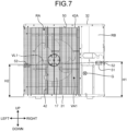
- FIG. 7 is a view illustrating the relationship between the positions of the handle portions formed on the housing and the position of the center of gravity of the outdoor machine when the outdoor machine is viewed from the front surface.
- components included in the outdoor machine are appropriately omitted to illustrate the position of the handle portion.
- FIG. 8 is also a schematic diagram illustrating the relationship between the height positions of the handle portions when the outdoor machine is lifted, as viewed from the front surface of the outdoor machine.
- the outdoor machine 2 includes three (plurality of) handle portions, which are the second handle portion 51, the third handle portion 52, and the fourth handle portion 53, in addition to the handgrip portion 50 functioning as the first handle portion.
- the second handle portion 51 to the fourth handle portion 53 are each provided on the side surface panel portion 33 of the housing 30, are recesses protruding to the inside of the housing 30, and are portions on which fingers of a worker are put when the outdoor machine 2 is transported or installed.
- the outdoor machine 2 has a different weight balance (position of the center of gravity) depending on the arrangement of circuit components such as the compressor 11 and the outdoor heat exchanger 13 which are housed inside the housing 30. Therefore, in order to facilitate the work of transporting and installing the outdoor machine 2 by a plurality of workers gripping the handle portion, the arrangement position of the handle portion is important.
- the handgrip portion (first handle portion) 50 and three handle portions, which are the second handle portion 51 to the fourth handle portion 53, are disposed so as to surround the position of the center of gravity G of the outdoor machine 2 when the housing 30 is viewed from the upper surface.
- the second handle portion 51 to the fourth handle portion 53 and the handgrip portion 50 are disposed such that the center of gravity G of the outdoor machine 2 is present in a first virtual area VA formed by connecting the first handle portion (handgrip portion) 50 to the fourth handle portion 53 adjacent to each other by a first virtual line VL when the housing 30 is viewed from the upper surface.
- the center of gravity G of the outdoor machine 2 refers to a point of action of the resultant force of gravity acting on the mass of each component constituting the outdoor machine 2, and for example, refers to a point at which the outdoor machine 2 can be supported in a well-balanced manner when the outdoor machine 2 is suspended.
- the center of gravity G of the outdoor machine 2 is regarded as an aggregate of the components of the outdoor machine 2, and can be calculated from the weights and the centers of gravity of the components by using a known formula.
- the center of gravity G of the outdoor machine 2 can also be obtained from a design drawing of the outdoor machine 2 by using computer-aided design (CAD) software.
- CAD computer-aided design
- the second handle portion 51 to the fourth handle portion 53 are provided at positions higher than the position of the center of gravity G when the housing 30 is viewed from the front surface (side surface).
- the second handle portion 51 to the fourth handle portion 53 are disposed such that the second handle portion 51 to the fourth handle portion 53 adjacent to each other are connected by a second virtual line (virtual line) VL1 and the center of gravity G of the outdoor machine 2 is present in a second virtual area VA1 below the second virtual line VL1 when the housing 30 is viewed from the front surface (side surface).
- the outdoor machine 2 since the outdoor machine 2 can be lifted and held at a position higher than the position of the center of gravity G, the force for rotating the outdoor machine 2 can be suppressed when the outdoor machine 2 is lifted. Therefore, the outdoor machine 2, which is a heavy object, can be transported and installed in a stable state.
- the second handle portion 51 to the fourth handle portion 53 are each provided near the corner portion of the side surface panel portion 33.
- the second handle portion 51 is provided on the right side surface side of the rear surface of the housing 30, that is, on the first rear surface portion 37A of the rear surface panel 37.
- the third handle portion 52 is provided on the front surface side of the right side surface of the housing 30, that is, on the second right side surface portion 38A of the right side surface panel 38.
- the third handle portion 52 is provided on the rear surface side of the left side surface, that is, at a corner portion of the left side surface panel 39 across the second left side surface portion 39A and the second rear surface portion 39B of the left side surface panel 39.
- the second handle portion 51 to the fourth handle portion 53 are each provided near the corner portions of the side surface panel portion 33, and thus the second handle portion 51 to the fourth handle portion 53 can be disposed at a distance from each other.
- the outdoor machine 2 can be transported by a plurality of persons, and the workability of transportation and installation can be improved.
- the outdoor machine 2 a large number of circuit components such as the compressor 11 and the water-refrigerant heat exchanger 15 are disposed in the machine chamber RB. Therefore, when the outdoor machine 2 is viewed from the upper surface, as illustrated in FIG. 6 , the position of the center of gravity G when the outdoor machine 2 is viewed from the upper surface is largely deviated from the center of the outdoor machine 2 toward the machine chamber RB side, that is, toward the right side surface (the second right side surface portion 38A of the right side surface panel 38) side of the housing 30. In this case, in order to stably transport the outdoor machine 2, the height positions at which the second handle portion 51 to the fourth handle portion 53 are provided are devised.
- the handle portions disposed on the side to which the center of gravity G is deviated that is, the second handle portion 51 disposed on the first rear surface portion 37A of the rear surface panel 37 and the third handle portion 52 disposed on the second right side surface portion 38A of the right side surface panel 38 are each provided at positions of the same height H1 from the bottom plate 31. According to this configuration, when one or two workers lift the outdoor machine 2 by putting their hands on the second handle portion 51 and the third handle portion 52, the occurrence of a difference in force received by the workers can be suppressed. Therefore, the outdoor machine 2 can be prevented from falling in the front-rear direction due to the difference in force, and the outdoor machine 2 can be stably transported.
- the fourth handle portion 53 disposed on the left side surface panel 39 on the opposite side is provided at a position of a height H2 from the bottom plate 31.
- the height H1 of the second handle portion 51 and the third handle portion 52 from the bottom plate 31 is set to be higher than the height H2 of the fourth handle portion 53 from the bottom plate 31.
- a larger weight load is applied to the second handle portion 51 and the third handle portion 52 on the side closer to the center of gravity G.
- the height H1 of the second handle portion 51 and the third handle portion 52 on the side closer to the center of gravity G is set higher than the height H2 of the fourth handle portion 53 on the side farther from the center of gravity G.
- the second handle portion 51 and the third handle portion 52 on the large weight load (so-called heavy) side are lifted can be suppressed to be lower than the height at which the fourth handle portion 53 on the small weight load (so-called light) side is lifted.
- the second handle portion 51 and the third handle portion 52 are held to reduce the burden on the worker who transports the outdoor machine 2, and the height of the second handle portion 51 and the third handle portion 52 from the bottom plate 31 when the outdoor machine 2 is lifted as illustrated in FIG. 8 is the same as the height of the fourth handle portion from the bottom plate 31, whereby the outdoor machine 2 can be stably transported.
- the height H1 of the second handle portion 51 and the third handle portion 52 from the bottom plate 31, the handle portions being on the side closer to the center of gravity G is set to be 450 (mm) or more and 500 (mm) or less.
- the height H2 of the fourth handle portion 53 from the bottom plate 31, the handle portion being on the side farther from the center of gravity G is set to be 410 (mm) or more and 460 (mm) or less.
- the worker M can lift the outdoor machine 2 to a needed height only by extension of the knees in a state of stretching the hips and arms. Therefore, physical damage to the worker during transportation can be reduced, and the outdoor machine 2 can be transported safely and efficiently. Further, by setting each of the heights H1 and H2 within the above-described ranges, the worker can raise the height between the bottom plate 31 of the outdoor machine 2 and the installation surface to be higher than the height dimensions of the skit for transportation and the leg portion for installation. Therefore, the outdoor machine 2 can be safely installed at the installation location.
- the second handle portion 51 provided on the above-described rear surface panel 37 is disposed near the corner portion of the housing 30 on the machine chamber RB side. Since heavy circuit components such as the compressor 11 and the water-refrigerant heat exchanger 15 are disposed in the machine chamber RB, the second handle portion 51 is disposed near the corner portion on the machine chamber RB side which is heavier than the heat exchange chamber RA, whereby the workability of the transporting work of the outdoor machine 2 is further improved.
- the second handle portion 51 to the fourth handle portion 53 are each provided on the side surface panel portion 33 excluding the service panel 40, that is, the rear surface panel 37, the right side surface panel 38, and the left side surface panel 39. According to this configuration, in a case where the service panel 40 is removed and the device in the machine chamber RB is operated, for example, even if a situation occurs in which the wiring does not reach the terminal portion 26 at the time of connection, the outdoor machine 2 can be easily moved by using the second handle portion 51 to the fourth handle portion 53.
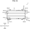
- FIG. 10 is a top view illustrating the positions of the handle portions provided in the outdoor machine 2
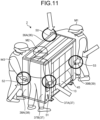
- FIG. 11 is a diagram illustrating a state in which three workers are transporting the outdoor machine 2.
- the housing 30 of the outdoor machine 2 is provided with the handgrip portion 50 functioning as the first handle portion, and the second handle portion 51 to the fourth handle portion 53.
- the handgrip portion 50 is provided on the first front surface portion 36A of the front surface panel 36
- the second handle portion 51 is provided on the first rear surface portion 37A of the rear surface panel 37.
- the third handle portion 52 is provided on the second right side surface portion 38A of the right side surface panel 38, and the fourth handle portion 53 is provided at a corner portion between the second left side surface portion 39A and the second rear surface portion 39B of the left side surface panel 39. Therefore, in the present embodiment, the first handle portion (handgrip portion) 50 to the fourth handle portion 53 can be disposed at a distance from each other, and the directions in which the hand of a worker enters the first handle portion (handgrip portion) 50 to the fourth handle portion 53 do not overlap as indicated by white arrows in FIG. 10 .
- FIG. 11 for example, three workers can easily transport the outdoor machine 2, which is a heavy object.
- one first worker M1 lifts the heat exchange chamber RA ( FIG. 6 ) side which is relatively light
- two second worker M2 and third worker M3 lift the machine chamber RB ( FIG. 6 ) side which is relatively heavy.
- the first worker M1 puts the right hand on the first handle portion (handgrip portion) 50 and puts the left hand on the fourth handle portion 53.
- the second worker M2 puts the right hand on the second handle portion 51 and holds the right side surface of the housing 30 with the left hand.
- the third worker M3 puts the right hand on the third handle portion 52 and puts the left hand on the first handle portion (handgrip portion) 50.
- the outdoor machine 2 can be stably transported.
- the outdoor machine 2 of the heat pump cycle apparatus 1 has the housing 30 that houses the outdoor heat exchanger 13 therein, and the housing 30 is provided with the first handle portion (handgrip portion) 50 to the fourth handle portion 53 for transporting the outdoor machine 2.
- the first handle portion 50 to the fourth handle portion 53 are provided at positions where the center of gravity G of the outdoor machine 2 is present in the first virtual area VA formed by connecting the handle portions adjacent to each other when the housing 30 is viewed from the upper surface. According to this configuration, since the center of gravity G of the outdoor machine 2 is positioned inside the first virtual area VA when the housing 30 is viewed from the upper surface, the upward force applied to the first handle portion 50 to the fourth handle portion 53 surrounds the downward force applied to the center of gravity G of the outdoor machine 2.
- the arrangement of the handle portion can be realized in which the outdoor machine 2, which is a heavy object, can be easily transported and installed in a stable state.
- the second handle portion 51 to the fourth handle portion 53 are provided at positions where the center of gravity is present in the second virtual area VA1 below the second virtual line VL1 formed by connecting the handle portions adjacent to each other when the housing 30 is viewed from the side surface. According to this configuration, since the outdoor machine 2 can be lifted and held at a position higher than the position of the center of gravity G, the force for rotating the outdoor machine 2 can be suppressed when the outdoor machine 2 is lifted. Therefore, the arrangement of the handle portion can be realized in which the outdoor machine 2, which is a heavy object, can be transported and installed in a stable state.
- the housing 30 has the bottom plate 31 which supports the outdoor heat exchanger 13, the top surface panel 32 disposed above the bottom plate 31, and the side surface panel portion 33 disposed between the bottom plate 31 and the top surface panel 32 to partition the inside and the outside of the housing 30, and the first handle portion (handgrip portion) 50 to the fourth handle portion 53 are provided on the side surface panel portion 33.
- the outdoor machine 2 can be transported and installed in a stable state by using the first handle portion (handgrip portion) 50 to the fourth handle portion 53.
- the outdoor machine 2 of the heat pump cycle apparatus 1 has the outdoor fan 17 which blows air to the outdoor heat exchanger 13, and the side surface panel portion 33 has: the front surface panel 36 having the blowout port 41 for blowing out the air heat-exchanged with the refrigerant in the outdoor heat exchanger 13 to the outside of the housing 30 by the rotation of the fan, the front surface panel forming a part of the front surface of the housing 30; the rear surface panel 37 disposed on the side opposite to the front surface panel 36 with the outdoor heat exchanger 13 interposed therebetween, the rear surface panel forming a part of the rear surface of the housing; the right side surface panel 38 forming a part of the right side surface of the housing 30; and the left side surface panel 39 forming a part of the left side surface of the housing 30, and the second handle portion 51 to the fourth handle portion 53 are each disposed near the corner portions of the housing 30.
- the second handle portion 51 to the fourth handle portion 53 are provided in a distributed manner at the four corners of the housing, and thus the
- the height H1 of the second handle portion 51 and the third handle portion 52 from the bottom plate 31 is set to be higher than the height H2 of the fourth handle portion 53 from the bottom plate 31, the handle portion being disposed on the left side surface panel 39 side opposite to the right side surface panel side.
- the height at which the second handle portion 51 and the third handle portion 52 on the large weight load (so-called heavy) side are lifted can be suppressed to be lower than the height at which the fourth handle portion 53 on the small weight load (so-called light) side is lifted.
- the burden on the workers who transport the outdoor machine 2 by holding the second handle portion 51 and the third handle portion 52 is reduced, and the outdoor machine 2 can be stably transported.
- the outdoor machine 2 of the heat pump cycle apparatus 1 has, on the right side surface panel 38 side to which the center of gravity G of the outdoor machine 2 is deviated, two handle portions, which are the second handle portion 51 and the third handle portion 52, disposed near the corner portion of the housing 30, and the two handle portions, which are the second handle portion 51 and the third handle portion 52, are each provided at positions of the same height H1 from the bottom plate 31.
- the outdoor machine 2 can be prevented from falling in the front-rear direction due to the difference in force, and the outdoor machine 2 can be stably transported.
- the handle portion provided on the front surface panel 36 is the first handle portion (handgrip portion) 50
- the handle portion provided on the rear surface panel 37 is the second handle portion 51
- the handle portion provided on the right side surface panel 38 is the third handle portion 52
- the handle portion provided on the left side surface panel 39 is the fourth handle portion 53
- the first handle portion (handgrip portion) 50 is disposed on the left side surface panel 39 side of the front surface panel 36
- the second handle portion 51 is disposed on the right side surface panel 38 side of the rear surface panel 37
- the third handle portion 52 is disposed on the front surface panel 36 side of the right side surface panel 38
- the fourth handle portion 53 is disposed on the rear surface panel 37 side of the left side surface panel 39.
- the first handle portion (handgrip portion) 50 to the fourth handle portion 53 can be disposed at a distance from each other. Therefore, the outdoor machine 2 can be transported by a plurality of persons, and the workability of transportation and installation can
- the outdoor machine 2 of the heat pump cycle apparatus 1 has the fan guard 42 disposed on the front surface panel 36 so as to cover the blowout port 41, and the fan guard 42 is disposed on the front surface panel 36 at a predetermined distance from the top surface panel 32, so that the handgrip portion 50 formed between the top surface panel 32 and the fan guard 42 is the first handle portion. According to this configuration, the workability of transportation and installation of the outdoor machine 2 can be improved without impairing the designability of the front surface side of the outdoor machine 2.
- the outdoor machine 2 of the heat pump cycle apparatus 1 has the compressor 11 and the water-refrigerant heat exchanger 15 that exchanges heat between a refrigerant and water, the heat exchange chamber RA in which the outdoor heat exchanger 13 and the outdoor fan 17 are disposed and the machine chamber RB in which the compressor 11 and the water-refrigerant heat exchanger 15 are disposed are provided inside the housing 30, the housing 30 has the service panel 40 that covers a part of the machine chamber RB and is detachable from the housing 30, and the first handle portion (handgrip portion) 50 to the fourth handle portion 53 are each provided on the front surface panel 36, the rear surface panel 37, the right side surface panel 38, and the left side surface panel 39, which exclude the service panel 40.
- the outdoor machine 2 in a case where the service panel 40 is removed and the device in the machine chamber RB is operated, for example, even if a situation occurs in which the wiring does not reach the terminal portion 26 at the time of connection, the outdoor machine 2 can be easily moved by using the first handle portion (handgrip portion) 5 to the fourth handle portion 53.
- FIG. 12 is a partially enlarged front view of an outdoor machine according to the modification as viewed from the front surface.
- a housing 30A of an outdoor machine 2A includes a fan guard 142, and the fan guard 142 has a widthwise central portion of an upper end portion (an end portion on the upper side) 142A extending to the top surface panel 32.
- the handgrip portions 50 may be formed only on both sides in the width direction of the first front surface portion 36A of the front surface panel 36, and also in this configuration, the worker can hold the outdoor machine 2A by inserting fingers into the handgrip portion 50, and can easily transport the outdoor machine 2A without impairing the designability.
- the embodiment is not limited thereto.
- a configuration is adopted in which three handle portions, which are the second handle portion 51 to the fourth handle portion 53, are provided in the housing 30, but four or more handle portions may be provided.
- a configuration is adopted in which the rear surface panel 37, the right side surface panel 38, and the left side surface panel 39 are each provided with one handle portion, but each panel may be provided with two or more handle portions.
- a configuration is adopted in which one fourth handle portion 53 is provided on the left side surface (left side surface panel 39) of the housing 30 on the side farther from the center of gravity G, but a handle portion may be provided at each of both corner portions of the left side surface. In this case, it is preferable that the heights from the bottom plate 31 to the respective handle portions are the same.
- the handgrip portion 50 functioning as the first handle portion is provided on the front surface side of the housing 30, but a first handle portion having the same configuration as the second handle portion 51 to the fourth handle portion 53 may be provided on the front surface panel 36.
- the heat pump cycle apparatus may be an air conditioner which performs air-conditioning operation by supplying a refrigerant to the indoor machine and causing the refrigerant to dissipate or absorb heat by the indoor heat exchanger without having the water-refrigerant heat exchanger in the outdoor machine.
Landscapes
- Engineering & Computer Science (AREA)
- Chemical & Material Sciences (AREA)
- Combustion & Propulsion (AREA)
- Mechanical Engineering (AREA)
- General Engineering & Computer Science (AREA)
- Other Air-Conditioning Systems (AREA)
Abstract
Description
- The present invention relates to a heat pump cycle apparatus having an outdoor machine in which a handle portion for transportation and installation is included in a housing.
- In general, an outdoor machine used in a heat pump cycle apparatus includes a compressor that compresses a refrigerant, a heat exchanger that performs heat exchange between the refrigerant and air, a fan that blows air to the heat exchanger, and the like, and these devices are housed in a housing. In this type of outdoor machine, the compressor and the heat exchanger increase in size as the air-conditioning capacity increases, and thus the outdoor machine itself tends to be large and heavy. Therefore, in the related art, there is disclosed a technique in which a plurality of handle portions for holding the outdoor machine is provided around a housing of the outdoor machine, thereby enabling a plurality of workers (for example, two workers) to transport and install the outdoor machine which is a large and heavy object (for example, refer to Patent Literature 1). In
Patent Literature 1, for example, when a side on which a blowout port for blowing out air to the outside of the housing is formed is defined as a front surface of the housing, handle portions are each provided on the front surface, a rear surface, and a left side surface of the housing. - Patent Literature 1:
JP 2019-143952 A - An outdoor machine has a different weight balance depending on the arrangement of circuit components such as a compressor and a heat exchanger which are housed inside a housing. Therefore, in a top view of the outdoor machine, the position of the center of gravity of the outdoor machine may deviate from the center of the housing. When the position of the center of gravity is deviated, there is a problem in that, during the work of transporting and installing the outdoor machine, the force received by a worker from each handle portion varies depending on the arrangement of handle portions, so that the balance is lost and the work becomes difficult.
- The disclosed technique has been made in view of the above, and an object of the disclosed technique is to provide a heat pump cycle apparatus having an arrangement of a handle portion that facilitates transportation and installation work of an outdoor machine.
- According to an aspect of an embodiment, a heat pump cycle apparatus includes an outdoor machine having a housing that houses a heat exchanger therein, wherein the housing is provided with at least three handle portions for transporting the outdoor machine, and the handle portions are provided at positions wherea center of gravity of the outdoor machine is present in an area formed by connecting the handle portions adjacent to each other when the housing is viewed from an upper surface.
- One aspect of the heat pump cycle apparatus disclosed in the present application can provide an outdoor machine having a handle portion that facilitates transportation and installation work of the outdoor machine.
-
-
FIG. 1 is a circuit configuration diagram illustrating an example of a refrigerant circuit and a water circuit of a heat pump cycle apparatus according to the present embodiment. -
FIG. 2 is an external perspective view of an outdoor machine as viewed from the front surface side. -
FIG. 3 is an external perspective view of the outdoor machine as viewed from the rear surface side. -
FIG. 4 is a perspective view illustrating an internal structure of the outdoor machine. -
FIG. 5 is a partial cross-sectional view of a handgrip portion of the outdoor machine taken along the line V-V inFIG. 2 as viewed from the X direction. -
FIG. 6 is a view illustrating the relationship between the positions of the handgrip portion and handle portions formed on a housing and the position of the center of gravity of the outdoor machine when the outdoor machine is viewed from the upper surface. -
FIG. 7 is a view illustrating the relationship between the positions of the handle portions formed on the housing and the position of the center of gravity of the outdoor machine when the outdoor machine is viewed from the front surface. -
FIG. 8 is a schematic diagram illustrating the relationship between the height positions of the handle portions when the outdoor machine is lifted, as viewed from the front surface of the outdoor machine. -
FIG. 9 is a schematic diagram illustrating a movement in which a worker lifts a load by bending and stretching the knees. -
FIG. 10 is a top view illustrating the positions of the handle portions provided in the outdoor machine. -
FIG. 11 is a diagram illustrating a state in which three workers are transporting the outdoor machine. -
FIG. 12 is a partially enlarged front view of an outdoor machine according to a modification as viewed from the front surface. - In the following, embodiments of a heat pump cycle apparatus disclosed in the present application will be described in detail with reference to the drawings. Note that the disclosed technique is not limited by the present embodiment. In addition, the embodiments described below may be appropriately modified within a range in which no contradiction occurs.
-
FIG. 1 is a circuit configuration diagram illustrating an example of a refrigerant circuit and a water circuit of a heat pump cycle apparatus according to the present embodiment. The heatpump cycle apparatus 1 includes anoutdoor machine 2 and anindoor machine 3, and theoutdoor machine 2 and theindoor machine 3 are connected to each other by a water pipe to form awater circuit 4. The heatpump cycle apparatus 1 performs cooling or heating of a room (space) in which theindoor machine 3 is disposed by circulating cold water or hot water in thewater circuit 4 of theoutdoor machine 2 and theindoor machine 3. Note that, although the heatpump cycle apparatus 1 illustrated inFIG. 1 includes oneindoor machine 3, the heat pump cycle apparatus may include a plurality ofindoor machines 3 connected in parallel to theoutdoor machine 2. - As illustrated in
FIG. 1 , theoutdoor machine 2 has acompressor 11, a four-way valve 12, an outdoor heat exchanger (heat exchanger) 13, anoutdoor expansion valve 14, a water-refrigerant heat exchanger 15, anaccumulator 16, and an outdoor fan (fan) 17. Thecompressor 11, the four-way valve 12, theoutdoor heat exchanger 13, theoutdoor expansion valve 14, the water-refrigerant heat exchanger 15, and theaccumulator 16 are connected to each other by arefrigerant pipe 18 to form arefrigerant circuit 10. Therefrigerant circuit 10 is completed inside theoutdoor machine 2 to constitute a refrigeration cycle. In addition to therefrigerant pipe 18, awater pipe 19 is connected to the water-refrigerant heat exchanger 15. Thewater pipe 19 extends to the outside of theoutdoor machine 2 and is connected to an indoor unit 23 (described later) of theindoor machine 3 to form thewater circuit 4. - The
compressor 11 is, for example, a capability variable compressor of a high-pressure container type capable of changing an operation capacity, and compresses a sucked low-pressure gas refrigerant to discharge a high-pressure gas refrigerant. The four-way valve 12 is connected to a refrigerant discharge side of thecompressor 11, and theaccumulator 16 is connected to a refrigerant suction side of the compressor. - The four-
way valve 12 is a valve for switching the direction in which the refrigerant flows in therefrigerant circuit 10, and include afirst port 12A to afourth port 12D. Thefirst port 12A is connected to the refrigerant discharge side of thecompressor 11. Thesecond port 12B is connected to one refrigerant inlet/outlet 13A of theoutdoor heat exchanger 13. Thethird port 12C is connected to the refrigerant inflow side of theaccumulator 16. Thefourth port 12D is connected to one refrigerant inlet/outlet 15A of the water-refrigerant heat exchanger 15. - As the
outdoor heat exchanger 13, for example, a fin-tube heat exchanger is used. Theoutdoor heat exchanger 13 exchanges heat between a refrigerant and the outside air taken into theoutdoor machine 2 by the rotation of theoutdoor fan 17. The other refrigerant inlet/outlet 13B of theoutdoor heat exchanger 13 is connected to the other refrigerant inlet/outlet 15B of the water-refrigerant heat exchanger 15 via theoutdoor expansion valve 14. Theoutdoor heat exchanger 13 functions as a condenser when the heatpump cycle apparatus 1 performs cooling operation, to condense (liquefy) the gas refrigerant. In addition, theoutdoor heat exchanger 13 functions as an evaporator when the heatpump cycle apparatus 1 performs heating operation, to evaporate (vaporize) the liquid refrigerant. - The
outdoor expansion valve 14 is provided between the other refrigerant inlet/outlet 13B of theoutdoor heat exchanger 13 and the other refrigerant inlet/outlet 15B of the water-refrigerant heat exchanger 15. Theoutdoor expansion valve 14 is, for example, an electronic expansion valve, and decompresses (expands) the liquid refrigerant passing through theoutdoor expansion valve 14 by adjusting the valve opening degree. - As the water-
refrigerant heat exchanger 15, for example, a plate heat exchanger is used. The water-refrigerant heat exchanger 15 exchanges heat between the refrigerant circulating in therefrigerant circuit 10 and the water circulating in thewater circuit 4. The water-refrigerant heat exchanger 15 functions as an evaporator when the heatpump cycle apparatus 1 performs cooling operation or defrosting operation, to evaporate (vaporize) the liquid refrigerant. The water-refrigerant heat exchanger 15 functions as a condenser when the heatpump cycle apparatus 1 performs heating operation, to condense (liquefy) the gas refrigerant. The water-refrigerant heat exchanger 15 has awater inlet 15C and awater outlet 15D, and thewater pipe 19 is connected to each of thewater inlet 15C and thewater outlet 15D to constitute a part of thewater circuit 4. In addition, for example, acirculation pump 21 for circulating water in thewater circuit 4 is provided on thewater inlet 15C side, and anair vent valve 22 for venting air entering thewater circuit 4 is provided on thewater outlet 15D side. - The refrigerant inflow side of the
accumulator 16 is connected to thethird port 12C of the four-way valve 12, and the refrigerant outflow side of the accumulator is connected to the refrigerant inflow side of thecompressor 11. Theaccumulator 16 is formed as a hollow high-pressure container, separates the refrigerant flowing into the inside thereof into a gas refrigerant and a liquid refrigerant, and causes only the gas refrigerant to be sucked into thecompressor 11. - The
outdoor fan 17 is disposed near theoutdoor heat exchanger 13 and blows air toward theoutdoor heat exchanger 13. Specifically, theoutdoor fan 17 takes the outside air into theoutdoor machine 2 from asuction port 44, which will be described later, of theoutdoor machine 2 and discharges the outside air heat-exchanged with the refrigerant in theoutdoor heat exchanger 13 to the outside of theoutdoor machine 2 from ablowout port 41, which will be described later. - On the other hand, the
indoor machine 3 has anindoor unit 23. As theindoor unit 23, for example, a floor heating device or a radiator is used. One refrigerant inlet/outlet 23A of theindoor unit 23 is connected to thewater outlet 15D of the water-refrigerant heat exchanger 15. The other refrigerant inlet/outlet 23B of theindoor unit 23 is connected to thewater inlet 15C of the water-refrigerant heat exchanger 15 via thecirculation pump 21. Thus, theindoor unit 23 is connected to the water-refrigerant heat exchanger 15 by thewater pipe 19 to constitute thewater circuit 4, and the water circulating in thewater circuit 4 dissipates or absorbs heat in theindoor unit 23, thereby heating or cooling the air-conditioned space in which theindoor machine 3 is installed. - The flow of refrigerant and the flow of water during the operation of the heat
pump cycle apparatus 1 will now be described. Note that, inFIG. 1 , the dashed arrows indicate the flow of the refrigerant during the heating operation, and the solid arrows indicate the flow of the refrigerant during the cooling operation. - When the heat
pump cycle apparatus 1 performs heating operation, the four-way valve 12 is switched so that thefirst port 12A communicates with thefourth port 12D and thesecond port 12B communicates with thethird port 12C. Thus, therefrigerant circuit 10 enters a heating cycle in which the water-refrigerant heat exchanger 15 functions as a condenser and theoutdoor heat exchanger 13 functions as an evaporator. - When the
compressor 11 is driven in the above-described state of therefrigerant circuit 10, the refrigerant discharged from thecompressor 11 flows into the four-way valve 12, and flows from the four-way valve 12 into the water-refrigerant heat exchanger 15. The high-temperature gas refrigerant flowing into the water-refrigerant heat exchanger 15 is condensed by exchanging heat with the water circulating in thewater circuit 4 of the water-refrigerant heat exchanger 15 by the movement of thecirculation pump 21. On the other hand, the water circulating in thewater circuit 4 is heated by the refrigerant in the water-refrigerant heat exchanger 15 to become hot water. The hot water flows into theindoor unit 23 of theindoor machine 3 through thewater pipe 19 of thewater circuit 4. The hot water then dissipates heat in theindoor unit 23, thereby heating the room in which theindoor machine 3 is installed. - The liquid refrigerant heat-exchanged with water and condensed in the water-
refrigerant heat exchanger 15 is decompressed while passing through theoutdoor expansion valve 14, and then flows into theoutdoor heat exchanger 13. The refrigerant flowing into theoutdoor heat exchanger 13 exchanges heat with the outside air flowing into theoutdoor machine 2 by the rotation of theoutdoor fan 17 and evaporates. The gas refrigerant evaporated in theoutdoor heat exchanger 13 passes through the four-way valve 12 and theaccumulator 16 in this order, and is sucked into thecompressor 11 and compressed again. - When the heat
pump cycle apparatus 1 performs cooling operation or defrosting operation, the four-way valve 12 is switched so that thefirst port 12A communicates with thesecond port 12B and thethird port 12C communicates with thefourth port 12D. Thus, therefrigerant circuit 10 enters a cooling cycle in which the water-refrigerant heat exchanger 15 functions as an evaporator and theoutdoor heat exchanger 13 functions as a condenser. - When the
compressor 11 is driven in the above-described state of therefrigerant circuit 10, the refrigerant discharged from thecompressor 11 flows into the four-way valve 12, and flows from the four-way valve 12 into theoutdoor heat exchanger 13. The high-temperature gas refrigerant flowing into theoutdoor heat exchanger 13 is condensed by exchanging heat with the outdoor air taken into theoutdoor machine 2 by the rotation of theoutdoor fan 17. Note that, when the defrosting operation is performed, the frost generated in theoutdoor heat exchanger 13 is melted by the heat of the refrigerant flowing into theoutdoor heat exchanger 13. - The liquid refrigerant condensed in the
outdoor heat exchanger 13 is decompressed while passing through theoutdoor expansion valve 14, and then flows into the water-refrigerant heat exchanger 15. The liquid refrigerant flowing into the water-refrigerant heat exchanger 15 is evaporated by exchanging heat with the water circulating in thewater circuit 4 of the water-refrigerant heat exchanger 15 by the operation of thecirculation pump 21. On the other hand, the water circulating in thewater circuit 4 is cooled by the refrigerant in the water-refrigerant heat exchanger 15 to become cold water. The cold water flows into theindoor unit 23 of theindoor machine 3 through thewater pipe 19 of thewater circuit 4. The cold water then absorbs heat from the indoor air in theindoor unit 23, thereby cooling the room in which theindoor machine 3 is installed. Note that, when the defrosting operation is performed, the circulation of water in thewater circuit 4 is stopped by stopping thecirculation pump 21 in order to suppress a decrease in the indoor temperature. - The gas refrigerant evaporated in the water-
refrigerant heat exchanger 15 passes through the four-way valve 12 and theaccumulator 16 in this order, and is sucked into thecompressor 11 and compressed again. - The external appearance and the internal structure of the
outdoor machine 2 will now be described.FIG. 2 is an external perspective view of the outdoor machine as viewed from the front surface side, andFIG. 3 is an external perspective view of the outdoor machine as viewed from the rear surface side.FIG. 4 is a perspective view illustrating the internal structure of the outdoor machine. Note that directions such as front and rear, up and down, and left and right described below indicate directions when theoutdoor machine 2 is viewed from the front surface side in a state in which theoutdoor machine 2 is installed, with a direction in which air is blown out from theblowout port 41, which will be described later, as the front. - As illustrated in
FIGS. 2 and3 , theoutdoor machine 2 includes ahousing 30 having a rectangular parallelepiped box shape in which the dimension in the left-right direction (width direction) is larger than the dimension in the front-rear direction (depth direction). Thehousing 30 includes a bottom plate (bottom surface panel) 31 disposed so as to face the installation surface, atop surface panel 32 disposed above thebottom plate 31 in the height direction, and a sidesurface panel portion 33 that connects thebottom plate 31 and thetop surface panel 32 and partitions the inside and the outside of thehousing 30. - As illustrated in
FIG. 4 , the inside of thehousing 30 is divided into a heat exchange chamber RA and a machine chamber RB by apartition plate 34 erected on thebottom plate 31. In the heat exchange chamber RA, theoutdoor heat exchanger 13 is disposed on the rear surface side of the heat exchange chamber RA, and theoutdoor fan 17 is disposed on the front surface side. Theoutdoor heat exchanger 13 is formed by being bent in an L-shape when viewed from the upper surface (thetop surface panel 32 side), and is supported by thebottom plate 31 along the left side surface side from the rear surface side of the heat exchange chamber RA. - The
outdoor fan 17 is attached to a pair ofsupport members bottom plate 31. Theoutdoor fan 17 is a so-called axial-flow fan, and draws outside air into the heat exchange chamber RA from the outside of theoutdoor machine 2, that is, from the suction port 44 (described later) formed on the rear surface side of theoutdoor heat exchanger 13 and a suction opening 46 (described later) formed on the left side surface side, by rotational driving of theoutdoor fan 17 by a fan motor not illustrated. Then, the air heat-exchanged with the refrigerant in theoutdoor heat exchanger 13 is blown out forward from the blowout port 41 (described later) formed on the front surface side of the heat exchange chamber RA. As described above, theoutdoor machine 2 is a front blowout type outdoor machine that blows out the heat-exchanged air from the front surface side. - In the lower space of the machine chamber RB, circuit components such as the
compressor 11, theaccumulator 16, the four-way valve 12 (FIG. 1 ), and the outdoor expansion valve 14 (FIG. 1 ) that constitute a part of therefrigerant circuit 10 are disposed, and the circuit components are connected to each other by therefrigerant pipe 18. Thecompressor 11 and theaccumulator 16 are fixed to thebottom plate 31. In the lower space of the machine chamber RB, circuit components such as the water-refrigerant heat exchanger 15, theair vent valve 22, and thecirculation pump 21 that constitute a part of thewater circuit 4 are disposed, and the circuit components are connected to each other by thewater pipe 19. In this embodiment, the water-refrigerant heat exchanger 15 is disposed near a corner portion between the rear surface side and the right side surface side in the lower space of the machine chamber RB (housing 30), and aconnection port 47 of thewater pipe 19, which will be described later, is provided on the rear surface side. - In the upper space of the machine chamber RB, an
electrical unit 25 having electrical components for controlling the operation of theoutdoor machine 2 is disposed. Theelectrical unit 25 includes acontrol board 27 and aterminal portion 26 to which wires such as a power supply line and a control line are connected, and is fixed to thepartition plate 34. In this embodiment, theterminal portion 26 is disposed near the right side surface side in the upper space of the machine chamber RB so as to face the right side surface side. - The side
surface panel portion 33 of thehousing 30 will now be described. The sidesurface panel portion 33 is formed by combining a plurality of panel members. In the present embodiment, as illustrated inFIGS. 2 and3 , the sidesurface panel portion 33 includes afront surface panel 36, arear surface panel 37, a rightside surface panel 38, a leftside surface panel 39, and aservice panel 40. Thefront surface panel 36, therear surface panel 37, the rightside surface panel 38, and the leftside surface panel 39 are each formed in an L-shape that includes two adjacent surfaces of thehousing 30 and a corner portion interposed between the two surfaces when thehousing 30 is viewed from the upper surface. - Specifically, the
front surface panel 36 integrally includes a firstfront surface portion 36A forming a part of the front surface of thehousing 30 and a first leftside surface portion 36B forming a part of the left side surface of thehousing 30. Therear surface panel 37 integrally includes a firstrear surface portion 37A forming a part of the rear surface of thehousing 30 and a first rightside surface portion 37B forming a part of the right side surface of thehousing 30. The rightside surface panel 38 integrally includes a second rightside surface portion 38A forming a part of the right side surface of thehousing 30 and a secondfront surface portion 38B forming a part of the front surface of thehousing 30. The leftside surface panel 39 integrally includes a second leftside surface portion 39A forming a part of the left side surface of thehousing 30 and a secondrear surface portion 39B forming a part of the rear surface of thehousing 30. - The first
front surface portion 36A of thefront surface panel 36 is disposed on the front surface side of the heat exchange chamber RA, and the secondfront surface portion 38B of the rightside surface panel 38 is disposed on the front surface side of the machine chamber RB. The firstfront surface portion 36A and the secondfront surface portion 38B are disposed side by side in the left-right direction and form the front surface of thehousing 30. The firstfront surface portion 36A is formed with theblowout port 41 through which the air heat-exchanged in the heat exchange chamber RA is blown out. Theblowout port 41 has, for example, acircular bell mouth 41A, and a portion of theoutdoor fan 17 is disposed within thebell mouth 41A. A net-like fan guard 42 that covers theblowout port 41 is provided in front of thefront surface panel 36. Thefan guard 42 is formed in an L-shape when thefan guard 42 is viewed from above, and is disposed along the firstfront surface portion 36A to the first leftside surface portion 36B of thefront surface panel 36. Thefan guard 42 is fixed to thefront surface panel 36 with a predetermined interval between an upper end portion (end portion on the upper side) 42A of thefan guard 42 and thetop surface panel 32. In addition, awater shielding plate 43 extending in the left-right (width) direction is provided above theblowout port 41 in the firstfront surface portion 36A. - The first
rear surface portion 37A of therear surface panel 37 and the secondrear surface portion 39B of the leftside surface panel 39 are disposed side by side in the left-right direction with an interval therebetween, and form a rear surface of thehousing 30. Theoutdoor heat exchanger 13 is disposed so as to be exposed between the firstrear surface portion 37A and the secondrear surface portion 39B, and the exposed area serves as thesuction port 44. A net-like fin guard 45 is provided behind thesuction port 44. In addition, the firstrear surface portion 37A is disposed on the rear surface side of the machine chamber RB, and a pair ofconnection ports water pipe 19 of thewater circuit 4 is provided at a lower portion of the firstrear surface portion 37A. - The second right
side surface portion 38A of the rightside surface panel 38 and the first rightside surface portion 37B of therear surface panel 37 are disposed side by side in the front-rear direction with an interval therebetween, and form a right side surface of thehousing 30. The above-describedservice panel 40 is detachably disposed between the second rightside surface portion 38A and the first rightside surface portion 37B. By removing theservice panel 40, the inside of the machine chamber RB can be accessed, and maintenance of theelectrical unit 25 and various circuit components can be easily performed. - The second left
side surface portion 39A of the leftside surface panel 39 and the first leftside surface portion 36B of thefront surface panel 36 are disposed side by side in the front-rear direction and form a left side surface of thehousing 30. The second leftside surface portion 39A faces a portion of theoutdoor heat exchanger 13, and the second leftside surface portion 39A is formed with a plurality ofsuction openings 46. - Since the
outdoor machine 2 is a heavy object, a plurality ofhandle portions outdoor machine 2 is provided on the sidesurface panel portion 33 of thehousing 30. Thehandle portions 51 to 53 are each disposed near the corner portions of thehousing 30. On the other hand, from the viewpoint of improving the designability of theoutdoor machine 2, thefront surface panel 36 of thehousing 30 is provided with ahandgrip portion 50 that functions as a handle portion with an inconspicuous appearance. - The
handgrip portion 50 will now be described.FIG. 5 is a partial cross-sectional view of the handgrip portion of the outdoor machine taken along the line V-V inFIG. 2 as viewed from the X direction. As illustrated inFIG. 5 , thehandgrip portion 50 is formed between theupper end portion 42A of thefan guard 42 disposed on thefront surface panel 36 and thetop surface panel 32, and is a portion into which fingers of a worker are inserted to hold theoutdoor machine 2 when theoutdoor machine 2 is transported or moved (installed). The firstfront surface portion 36A of thefront surface panel 36 is disposed rearward of afront end portion 32A of thetop surface panel 32, and thehandgrip portion 50 is formed by connecting a bent portion 36A1 formed by bending an upper end of the firstfront surface portion 36A forward and thefront end portion 32A of thetop surface panel 32. - Specifically, the
front end portion 32A (the end portion on the front side) of thetop surface panel 32 is bent downward, and the bent portion 36A1 has a first bent portion 36A11 that is bent forward and a second bent portion 36A12 that is formed by further bending a tip of the first bent portion 36A11 upward. By fixing the second bent portion 36A12 of the firstfront surface portion 36A and thefront end portion 32A of thetop surface panel 32 with a screw, thehandgrip portion 50 is formed as a structure in which the top surface front portion of thehousing 30 extends forward in an eaves shape. Note that the first bent portion 36A11 may be provided with a recessed portion that is recessed upward so as to be more easily gripped by the worker. - Thus, the
outdoor machine 2 can be held during transportation by putting fingers on thehandgrip portion 50. In addition, thehandgrip portion 50 is formed as a part of the structure of thehousing 30 between theupper end portion 42A of thefan guard 42 and thetop surface panel 32. Therefore, even when theoutdoor machine 2 is viewed from the front surface side in particular, thehandgrip portion 50 is unlikely to be visually recognized as a so-called handle portion, and thus the designability of theoutdoor machine 2 can be prevented from being impaired. - In the present embodiment, as illustrated in
FIG. 2 , thehandgrip portion 50 is formed along the width direction (left-right direction) of the firstfront surface portion 36A of thefront surface panel 36. Therefore, a worker can optionally select a place to hold thehandgrip portion 50, and the workability at the time of transportation and installation can be improved. - The handle portion will now be described.
FIG. 6 is a view illustrating the relationship between the positions of the handgrip portion and handle portions formed on the housing and the position of the center of gravity of the outdoor machine when the outdoor machine is viewed from the upper surface.FIG. 7 is a view illustrating the relationship between the positions of the handle portions formed on the housing and the position of the center of gravity of the outdoor machine when the outdoor machine is viewed from the front surface. InFIGS. 6 and7 , components included in the outdoor machine are appropriately omitted to illustrate the position of the handle portion.FIG. 8 is also a schematic diagram illustrating the relationship between the height positions of the handle portions when the outdoor machine is lifted, as viewed from the front surface of the outdoor machine.FIG. 9 is a schematic diagram illustrating a movement in which a worker lifts a load by bending and stretching the knees. As described above, in the present embodiment, theoutdoor machine 2 includes three (plurality of) handle portions, which are thesecond handle portion 51, thethird handle portion 52, and thefourth handle portion 53, in addition to thehandgrip portion 50 functioning as the first handle portion. Thesecond handle portion 51 to thefourth handle portion 53 are each provided on the sidesurface panel portion 33 of thehousing 30, are recesses protruding to the inside of thehousing 30, and are portions on which fingers of a worker are put when theoutdoor machine 2 is transported or installed. In general, theoutdoor machine 2 has a different weight balance (position of the center of gravity) depending on the arrangement of circuit components such as thecompressor 11 and theoutdoor heat exchanger 13 which are housed inside thehousing 30. Therefore, in order to facilitate the work of transporting and installing theoutdoor machine 2 by a plurality of workers gripping the handle portion, the arrangement position of the handle portion is important. - In the present embodiment, as illustrated in
FIG. 6 , the handgrip portion (first handle portion) 50 and three handle portions, which are thesecond handle portion 51 to thefourth handle portion 53, are disposed so as to surround the position of the center of gravity G of theoutdoor machine 2 when thehousing 30 is viewed from the upper surface. In other words, thesecond handle portion 51 to thefourth handle portion 53 and thehandgrip portion 50 are disposed such that the center of gravity G of theoutdoor machine 2 is present in a first virtual area VA formed by connecting the first handle portion (handgrip portion) 50 to thefourth handle portion 53 adjacent to each other by a first virtual line VL when thehousing 30 is viewed from the upper surface. - Here, the center of gravity G of the
outdoor machine 2 refers to a point of action of the resultant force of gravity acting on the mass of each component constituting theoutdoor machine 2, and for example, refers to a point at which theoutdoor machine 2 can be supported in a well-balanced manner when theoutdoor machine 2 is suspended. The center of gravity G of theoutdoor machine 2 is regarded as an aggregate of the components of theoutdoor machine 2, and can be calculated from the weights and the centers of gravity of the components by using a known formula. In addition, the center of gravity G of theoutdoor machine 2 can also be obtained from a design drawing of theoutdoor machine 2 by using computer-aided design (CAD) software. - When the
outdoor machine 2 is lifted, an upward force is applied to each of the first handle portion (handgrip portion) 50 to thefourth handle portion 53. As described above, since the center of gravity G of theoutdoor machine 2 is present inside the first virtual area VA, the upward force applied to the first handle portion (handgrip portion) 50 to thefourth handle portion 53 surrounds the downward force (gravity) applied to the center of gravity G of theoutdoor machine 2. Therefore, when theoutdoor machine 2 is lifted, the upward force and the downward force applied to theoutdoor machine 2 are easily balanced, and the force for rotating theoutdoor machine 2 can be suppressed. Therefore, theoutdoor machine 2, which is a heavy object, can be transported and installed in a stable state. - As illustrated in
FIG. 7 , thesecond handle portion 51 to thefourth handle portion 53 are provided at positions higher than the position of the center of gravity G when thehousing 30 is viewed from the front surface (side surface). In other words, thesecond handle portion 51 to thefourth handle portion 53 are disposed such that thesecond handle portion 51 to thefourth handle portion 53 adjacent to each other are connected by a second virtual line (virtual line) VL1 and the center of gravity G of theoutdoor machine 2 is present in a second virtual area VA1 below the second virtual line VL1 when thehousing 30 is viewed from the front surface (side surface). - According to this configuration, since the
outdoor machine 2 can be lifted and held at a position higher than the position of the center of gravity G, the force for rotating theoutdoor machine 2 can be suppressed when theoutdoor machine 2 is lifted. Therefore, theoutdoor machine 2, which is a heavy object, can be transported and installed in a stable state. - As illustrated in
FIGS. 2 and3 , thesecond handle portion 51 to thefourth handle portion 53 are each provided near the corner portion of the sidesurface panel portion 33. Specifically, thesecond handle portion 51 is provided on the right side surface side of the rear surface of thehousing 30, that is, on the firstrear surface portion 37A of therear surface panel 37. Thethird handle portion 52 is provided on the front surface side of the right side surface of thehousing 30, that is, on the second rightside surface portion 38A of the rightside surface panel 38. In addition, thethird handle portion 52 is provided on the rear surface side of the left side surface, that is, at a corner portion of the leftside surface panel 39 across the second leftside surface portion 39A and the secondrear surface portion 39B of the leftside surface panel 39. - As described above, the
second handle portion 51 to thefourth handle portion 53 are each provided near the corner portions of the sidesurface panel portion 33, and thus thesecond handle portion 51 to thefourth handle portion 53 can be disposed at a distance from each other. Theoutdoor machine 2 can be transported by a plurality of persons, and the workability of transportation and installation can be improved. - In the
outdoor machine 2, a large number of circuit components such as thecompressor 11 and the water-refrigerant heat exchanger 15 are disposed in the machine chamber RB. Therefore, when theoutdoor machine 2 is viewed from the upper surface, as illustrated inFIG. 6 , the position of the center of gravity G when theoutdoor machine 2 is viewed from the upper surface is largely deviated from the center of theoutdoor machine 2 toward the machine chamber RB side, that is, toward the right side surface (the second rightside surface portion 38A of the right side surface panel 38) side of thehousing 30. In this case, in order to stably transport theoutdoor machine 2, the height positions at which thesecond handle portion 51 to thefourth handle portion 53 are provided are devised. - In the present embodiment, the handle portions disposed on the side to which the center of gravity G is deviated, that is, the
second handle portion 51 disposed on the firstrear surface portion 37A of therear surface panel 37 and thethird handle portion 52 disposed on the second rightside surface portion 38A of the rightside surface panel 38 are each provided at positions of the same height H1 from thebottom plate 31. According to this configuration, when one or two workers lift theoutdoor machine 2 by putting their hands on thesecond handle portion 51 and thethird handle portion 52, the occurrence of a difference in force received by the workers can be suppressed. Therefore, theoutdoor machine 2 can be prevented from falling in the front-rear direction due to the difference in force, and theoutdoor machine 2 can be stably transported. - The
fourth handle portion 53 disposed on the leftside surface panel 39 on the opposite side is provided at a position of a height H2 from thebottom plate 31. The height H1 of thesecond handle portion 51 and thethird handle portion 52 from thebottom plate 31 is set to be higher than the height H2 of thefourth handle portion 53 from thebottom plate 31. When theoutdoor machine 2 in which the position of the center of gravity G is deviated is lifted, a larger weight load is applied to thesecond handle portion 51 and thethird handle portion 52 on the side closer to the center of gravity G. In the present embodiment, the height H1 of thesecond handle portion 51 and thethird handle portion 52 on the side closer to the center of gravity G is set higher than the height H2 of thefourth handle portion 53 on the side farther from the center of gravity G. Therefore, as illustrated inFIG. 8 , when theoutdoor machine 2 is lifted, the height at which thesecond handle portion 51 and thethird handle portion 52 on the large weight load (so-called heavy) side are lifted can be suppressed to be lower than the height at which thefourth handle portion 53 on the small weight load (so-called light) side is lifted. Thus, thesecond handle portion 51 and thethird handle portion 52 are held to reduce the burden on the worker who transports theoutdoor machine 2, and the height of thesecond handle portion 51 and thethird handle portion 52 from thebottom plate 31 when theoutdoor machine 2 is lifted as illustrated inFIG. 8 is the same as the height of the fourth handle portion from thebottom plate 31, whereby theoutdoor machine 2 can be stably transported. - In the present embodiment, the height H1 of the
second handle portion 51 and thethird handle portion 52 from thebottom plate 31, the handle portions being on the side closer to the center of gravity G, is set to be 450 (mm) or more and 500 (mm) or less. In addition, the height H2 of thefourth handle portion 53 from thebottom plate 31, the handle portion being on the side farther from the center of gravity G, is set to be 410 (mm) or more and 460 (mm) or less. By setting each of the heights H1 and H2 within the above-described ranges, when an adult (for example, male) worker M having a general physique lifts theoutdoor machine 2 as illustrated inFIG. 9 , the worker M can lift theoutdoor machine 2 to a needed height only by extension of the knees in a state of stretching the hips and arms. Therefore, physical damage to the worker during transportation can be reduced, and theoutdoor machine 2 can be transported safely and efficiently. Further, by setting each of the heights H1 and H2 within the above-described ranges, the worker can raise the height between thebottom plate 31 of theoutdoor machine 2 and the installation surface to be higher than the height dimensions of the skit for transportation and the leg portion for installation. Therefore, theoutdoor machine 2 can be safely installed at the installation location. - In the present embodiment, the
second handle portion 51 provided on the above-describedrear surface panel 37 is disposed near the corner portion of thehousing 30 on the machine chamber RB side. Since heavy circuit components such as thecompressor 11 and the water-refrigerant heat exchanger 15 are disposed in the machine chamber RB, thesecond handle portion 51 is disposed near the corner portion on the machine chamber RB side which is heavier than the heat exchange chamber RA, whereby the workability of the transporting work of theoutdoor machine 2 is further improved. - In the present embodiment, the
second handle portion 51 to thefourth handle portion 53 are each provided on the sidesurface panel portion 33 excluding theservice panel 40, that is, therear surface panel 37, the rightside surface panel 38, and the leftside surface panel 39. According to this configuration, in a case where theservice panel 40 is removed and the device in the machine chamber RB is operated, for example, even if a situation occurs in which the wiring does not reach theterminal portion 26 at the time of connection, theoutdoor machine 2 can be easily moved by using thesecond handle portion 51 to thefourth handle portion 53. - The movement of transporting the
outdoor machine 2 will now be described.FIG. 10 is a top view illustrating the positions of the handle portions provided in theoutdoor machine 2, andFIG. 11 is a diagram illustrating a state in which three workers are transporting theoutdoor machine 2. As described above, thehousing 30 of theoutdoor machine 2 is provided with thehandgrip portion 50 functioning as the first handle portion, and thesecond handle portion 51 to thefourth handle portion 53. Thehandgrip portion 50 is provided on the firstfront surface portion 36A of thefront surface panel 36, and thesecond handle portion 51 is provided on the firstrear surface portion 37A of therear surface panel 37. In addition, thethird handle portion 52 is provided on the second rightside surface portion 38A of the rightside surface panel 38, and thefourth handle portion 53 is provided at a corner portion between the second leftside surface portion 39A and the secondrear surface portion 39B of the leftside surface panel 39. Therefore, in the present embodiment, the first handle portion (handgrip portion) 50 to thefourth handle portion 53 can be disposed at a distance from each other, and the directions in which the hand of a worker enters the first handle portion (handgrip portion) 50 to thefourth handle portion 53 do not overlap as indicated by white arrows inFIG. 10 . - Therefore, as illustrated in
FIG. 11 , for example, three workers can easily transport theoutdoor machine 2, which is a heavy object. In the example ofFIG. 11 , one first worker M1 lifts the heat exchange chamber RA (FIG. 6 ) side which is relatively light, and two second worker M2 and third worker M3 lift the machine chamber RB (FIG. 6 ) side which is relatively heavy. In this case, the first worker M1 puts the right hand on the first handle portion (handgrip portion) 50 and puts the left hand on thefourth handle portion 53. On the other hand, the second worker M2 puts the right hand on thesecond handle portion 51 and holds the right side surface of thehousing 30 with the left hand. In addition, the third worker M3 puts the right hand on thethird handle portion 52 and puts the left hand on the first handle portion (handgrip portion) 50. Thus, since the three first worker M1 to third worker M3 lift theoutdoor machine 2 at intervals around theoutdoor machine 2, theoutdoor machine 2 can be stably transported. - As described above, the
outdoor machine 2 of the heatpump cycle apparatus 1 according to the present embodiment has thehousing 30 that houses theoutdoor heat exchanger 13 therein, and thehousing 30 is provided with the first handle portion (handgrip portion) 50 to thefourth handle portion 53 for transporting theoutdoor machine 2. Thefirst handle portion 50 to thefourth handle portion 53 are provided at positions where the center of gravity G of theoutdoor machine 2 is present in the first virtual area VA formed by connecting the handle portions adjacent to each other when thehousing 30 is viewed from the upper surface. According to this configuration, since the center of gravity G of theoutdoor machine 2 is positioned inside the first virtual area VA when thehousing 30 is viewed from the upper surface, the upward force applied to thefirst handle portion 50 to thefourth handle portion 53 surrounds the downward force applied to the center of gravity G of theoutdoor machine 2. Therefore, when theoutdoor machine 2 is lifted, the upward force and the downward force applied to theoutdoor machine 2 are easily balanced, and the force for rotating theoutdoor machine 2 can be suppressed. Therefore, the arrangement of the handle portion can be realized in which theoutdoor machine 2, which is a heavy object, can be easily transported and installed in a stable state. - In the
outdoor machine 2 of the heatpump cycle apparatus 1 according to the present embodiment, thesecond handle portion 51 to thefourth handle portion 53 are provided at positions where the center of gravity is present in the second virtual area VA1 below the second virtual line VL1 formed by connecting the handle portions adjacent to each other when thehousing 30 is viewed from the side surface. According to this configuration, since theoutdoor machine 2 can be lifted and held at a position higher than the position of the center of gravity G, the force for rotating theoutdoor machine 2 can be suppressed when theoutdoor machine 2 is lifted. Therefore, the arrangement of the handle portion can be realized in which theoutdoor machine 2, which is a heavy object, can be transported and installed in a stable state. - In the
outdoor machine 2 of the heatpump cycle apparatus 1 according to the present embodiment, thehousing 30 has thebottom plate 31 which supports theoutdoor heat exchanger 13, thetop surface panel 32 disposed above thebottom plate 31, and the sidesurface panel portion 33 disposed between thebottom plate 31 and thetop surface panel 32 to partition the inside and the outside of thehousing 30, and the first handle portion (handgrip portion) 50 to thefourth handle portion 53 are provided on the sidesurface panel portion 33. According to this configuration, theoutdoor machine 2 can be transported and installed in a stable state by using the first handle portion (handgrip portion) 50 to thefourth handle portion 53. - The
outdoor machine 2 of the heatpump cycle apparatus 1 according to the present embodiment has theoutdoor fan 17 which blows air to theoutdoor heat exchanger 13, and the sidesurface panel portion 33 has: thefront surface panel 36 having theblowout port 41 for blowing out the air heat-exchanged with the refrigerant in theoutdoor heat exchanger 13 to the outside of thehousing 30 by the rotation of the fan, the front surface panel forming a part of the front surface of thehousing 30; therear surface panel 37 disposed on the side opposite to thefront surface panel 36 with theoutdoor heat exchanger 13 interposed therebetween, the rear surface panel forming a part of the rear surface of the housing; the rightside surface panel 38 forming a part of the right side surface of thehousing 30; and the leftside surface panel 39 forming a part of the left side surface of thehousing 30, and thesecond handle portion 51 to thefourth handle portion 53 are each disposed near the corner portions of thehousing 30. According to this configuration, thesecond handle portion 51 to thefourth handle portion 53 are provided in a distributed manner at the four corners of the housing, and thus the workability of transportation and installation work of theoutdoor machine 2 can be improved. - In the
outdoor machine 2 of the heatpump cycle apparatus 1 according to the present embodiment, if the center of gravity G of theoutdoor machine 2 is deviated toward the rightside surface panel 38 side of thehousing 30 when thehousing 30 is viewed from the upper surface, the height H1 of thesecond handle portion 51 and thethird handle portion 52 from thebottom plate 31, the handle portions being disposed on the rightside surface panel 38 side to which the center of gravity G is deviated, is set to be higher than the height H2 of thefourth handle portion 53 from thebottom plate 31, the handle portion being disposed on the leftside surface panel 39 side opposite to the right side surface panel side. According to this configuration, when theoutdoor machine 2 is lifted, the height at which thesecond handle portion 51 and thethird handle portion 52 on the large weight load (so-called heavy) side are lifted can be suppressed to be lower than the height at which thefourth handle portion 53 on the small weight load (so-called light) side is lifted. Thus, the burden on the workers who transport theoutdoor machine 2 by holding thesecond handle portion 51 and thethird handle portion 52 is reduced, and theoutdoor machine 2 can be stably transported. - The
outdoor machine 2 of the heatpump cycle apparatus 1 according to the present embodiment has, on the rightside surface panel 38 side to which the center of gravity G of theoutdoor machine 2 is deviated, two handle portions, which are thesecond handle portion 51 and thethird handle portion 52, disposed near the corner portion of thehousing 30, and the two handle portions, which are thesecond handle portion 51 and thethird handle portion 52, are each provided at positions of the same height H1 from thebottom plate 31. According to this configuration, when one or two workers lift theoutdoor machine 2 by putting their hands on thesecond handle portion 51 and thethird handle portion 52, the occurrence of a difference in force received by the workers can be suppressed.
Therefore, theoutdoor machine 2 can be prevented from falling in the front-rear direction due to the difference in force, and theoutdoor machine 2 can be stably transported. - In the
outdoor machine 2 of the heatpump cycle apparatus 1 according to the present embodiment, when the handle portion provided on thefront surface panel 36 is the first handle portion (handgrip portion) 50, the handle portion provided on therear surface panel 37 is thesecond handle portion 51, the handle portion provided on the rightside surface panel 38 is thethird handle portion 52, and the handle portion provided on the leftside surface panel 39 is thefourth handle portion 53, the first handle portion (handgrip portion) 50 is disposed on the leftside surface panel 39 side of thefront surface panel 36, thesecond handle portion 51 is disposed on the rightside surface panel 38 side of therear surface panel 37, thethird handle portion 52 is disposed on thefront surface panel 36 side of the rightside surface panel 38, and thefourth handle portion 53 is disposed on therear surface panel 37 side of the leftside surface panel 39. According to this configuration, the first handle portion (handgrip portion) 50 to thefourth handle portion 53 can be disposed at a distance from each other. Therefore, theoutdoor machine 2 can be transported by a plurality of persons, and the workability of transportation and installation can be improved. - The
outdoor machine 2 of the heatpump cycle apparatus 1 according to the present embodiment has thefan guard 42 disposed on thefront surface panel 36 so as to cover theblowout port 41, and thefan guard 42 is disposed on thefront surface panel 36 at a predetermined distance from thetop surface panel 32, so that thehandgrip portion 50 formed between thetop surface panel 32 and thefan guard 42 is the first handle portion. According to this configuration, the workability of transportation and installation of theoutdoor machine 2 can be improved without impairing the designability of the front surface side of theoutdoor machine 2. - The
outdoor machine 2 of the heatpump cycle apparatus 1 according to the present embodiment has thecompressor 11 and the water-refrigerant heat exchanger 15 that exchanges heat between a refrigerant and water, the heat exchange chamber RA in which theoutdoor heat exchanger 13 and theoutdoor fan 17 are disposed and the machine chamber RB in which thecompressor 11 and the water-refrigerant heat exchanger 15 are disposed are provided inside thehousing 30, thehousing 30 has theservice panel 40 that covers a part of the machine chamber RB and is detachable from thehousing 30, and the first handle portion (handgrip portion) 50 to thefourth handle portion 53 are each provided on thefront surface panel 36, therear surface panel 37, the rightside surface panel 38, and the leftside surface panel 39, which exclude theservice panel 40. According to this configuration, in a case where theservice panel 40 is removed and the device in the machine chamber RB is operated, for example, even if a situation occurs in which the wiring does not reach theterminal portion 26 at the time of connection, theoutdoor machine 2 can be easily moved by using the first handle portion (handgrip portion) 5 to thefourth handle portion 53. - A modification of the present embodiment will now be described.
FIG. 12 is a partially enlarged front view of an outdoor machine according to the modification as viewed from the front surface. In the above-described embodiment, the configuration in which thehandgrip portion 50 is formed along the width direction of the firstfront surface portion 36A of thefront surface panel 36 has been described, but the embodiment is not limited thereto. For example, as illustrated inFIG. 12 , ahousing 30A of anoutdoor machine 2A includes afan guard 142, and thefan guard 142 has a widthwise central portion of an upper end portion (an end portion on the upper side) 142A extending to thetop surface panel 32. As described above, thehandgrip portions 50 may be formed only on both sides in the width direction of the firstfront surface portion 36A of thefront surface panel 36, and also in this configuration, the worker can hold theoutdoor machine 2A by inserting fingers into thehandgrip portion 50, and can easily transport theoutdoor machine 2A without impairing the designability. - As described above, an embodiment of the outdoor machine of the heat pump cycle apparatus according to the present disclosure has been described, but the embodiment is not limited thereto. For example, in the present embodiment, a configuration is adopted in which three handle portions, which are the
second handle portion 51 to thefourth handle portion 53, are provided in thehousing 30, but four or more handle portions may be provided. A configuration is adopted in which therear surface panel 37, the rightside surface panel 38, and the leftside surface panel 39 are each provided with one handle portion, but each panel may be provided with two or more handle portions. In the present embodiment, a configuration is adopted in which onefourth handle portion 53 is provided on the left side surface (left side surface panel 39) of thehousing 30 on the side farther from the center of gravity G, but a handle portion may be provided at each of both corner portions of the left side surface. In this case, it is preferable that the heights from thebottom plate 31 to the respective handle portions are the same. In the present embodiment, thehandgrip portion 50 functioning as the first handle portion is provided on the front surface side of thehousing 30, but a first handle portion having the same configuration as thesecond handle portion 51 to thefourth handle portion 53 may be provided on thefront surface panel 36. Further, in the present embodiment, a heat pump cycle apparatus which performs air-conditioning operation by circulating water between theoutdoor machine 2 and theindoor machine 3 has been described, but the heat pump cycle apparatus may be an air conditioner which performs air-conditioning operation by supplying a refrigerant to the indoor machine and causing the refrigerant to dissipate or absorb heat by the indoor heat exchanger without having the water-refrigerant heat exchanger in the outdoor machine. -
- 1 HEAT PUMP CYCLE APPARATUS
- 2, 2A OUTDOOR MACHINE
- 11 COMPRESSOR
- 13 OUTDOOR HEAT EXCHANGER (HEAT EXCHANGER)
- 15 WATER-REFRIGERANT HEAT EXCHANGER
- 17 OUTDOOR FAN (FAN)
- 30, 30A HOUSING
- 31 BOTTOM PLATE (BOTTOM SURFACE PANEL)
- 32 TOP SURFACE PANEL
- 32A FRONT END PORTION (END PORTION ON FRONT SIDE)
- 33 SIDE SURFACE PANEL PORTION
- 36 FRONT SURFACE PANEL
- 36A FIRST FRONT SURFACE PORTION
- 36A1 BENT PORTION
- 36A11 FIRST BENT PORTION
- 36A12 SECOND BENT PORTION
- 36B FIRST LEFT SIDE SURFACE PORTION
- 37 REAR SURFACE PANEL
- 37A FIRST REAR SURFACE PORTION
- 37B FIRST RIGHT SIDE SURFACE PORTION
- 38 RIGHT SIDE SURFACE PANEL
- 38A SECOND RIGHT SIDE SURFACE PORTION
- 38B SECOND FRONT SURFACE PORTION
- 39 LEFT SIDE SURFACE PANEL
- 39A SECOND LEFT SIDE SURFACE PORTION
- 39B SECOND REAR SURFACE PORTION
- 40 SERVICE PANEL
- 41 BLOWOUT PORT
- 42, 142 FAN GUARD
- 42A, 142A UPPER END PORTION (END PORTION ON UPPER SIDE)
- 50 HANDGRIP PORTION (FIRST HANDLE PORTION)
- 51 SECOND HANDLE PORTION
- 52 THIRD HANDLE PORTION
- 53 FOURTH HANDLE PORTION
- G CENTER OF GRAVITY
- RA HEAT EXCHANGE CHAMBER
- RB MACHINE CHAMBER
- VA FIRST VIRTUAL AREA (AREA FORMED BY CONNECTING HANDLE PORTIONS ADJACENT TO EACH OTHER WHEN HOUSING IS VIEWED FROM UPPER SURFACE)
- VA1 SECOND VIRTUAL AREA (AREA BELOW VIRTUAL LINE FORMED BY CONNECTING HANDLE PORTIONS ADJACENT TO EACH OTHER WHEN HOUSING IS VIEWED FROM SIDE SURFACE)
- VL FIRST VIRTUAL LINE
- VL1 SECOND VIRTUAL LINE (VIRTUAL LINE)
Claims (9)
- A heat pump cycle apparatus comprising an outdoor machine having a housing that houses a heat exchanger therein, whereinthe housing is provided with at least three handle portions for transporting the outdoor machine, andthe handle portions are provided at positions wherea center of gravity of the outdoor machine is present in an area formed by connecting the handle portions adjacent to each other when the housing is viewed from an upper surface.
- The heat pump cycle apparatus according to claim 1, wherein the handle portions are provided at positions where the center of gravity is present in an area below a virtual line formed by connecting the handle portions adjacent to each other when the housing is viewed from a side surface.
- The heat pump cycle apparatus according to claim 1 or 2, whereinthe housing has a bottom surface panel which supports the heat exchanger, a top surface panel disposed above the bottom surface panel, and a side surface panel portion disposed between the bottom surface panel and the top surface panel to partition an inside and an outside of the housing, anda plurality of the handle portions are provided on the side surface panel portion.
- The heat pump cycle apparatus according to claim 3, having a fan which blows air to the heat exchanger, whereinthe side surface panel portion has: a front surface panel having a blowout port for blowing out air heat-exchanged with a refrigerant in the heat exchanger to an outside of the housing by rotation of the fan, the front surface panel forming a part of a front surface of the housing; a rear surface panel disposed on a side opposite to the front surface panel with the heat exchanger interposed therebetween, the rear surface panel forming a part of a rear surface of the housing; a right side surface panel forming a part of a right side surface of the housing; and a left side surface panel forming a part of a left side surface of the housing, anda plurality of the handle portions are disposed near corner portions of the housing, respectively.
- The heat pump cycle apparatus according to claim 3 or 4, whereinif the center of gravity of the outdoor machine is deviated toward one of the right side surface panel side or the left side surface panel side of the housing when the housing is viewed from an upper surface,a height of the handle portions from the bottom surface panel of the housing, the handle portions being disposed on one side surface panel side to which the center of gravity is deviated, is higher than a height of the handle portions from the bottom surface panel, the handle portions being disposed on an other side surface panel side.
- The heat pump cycle apparatus according to claim 5, having, on one side surface panel side to which the center of gravity is deviated, two handle portions disposed near the corner portions of the housing, wherein
the two handle portions are provided at positions of a same height from the bottom surface panel. - The heat pump cycle apparatus according to any one of claims 4 to 6, whereinwhen a handle portion provided on the front surface panel is a first handle portion, a handle portion provided on the rear surface panel is a second handle portion, a handle portion provided on the right side surface panel is a third handle portion, and a handle portion provided on the left side surface panel is a fourth handle portion,the first handle portion is disposed on the left side surface panel side of the front surface panel,the second handle portion is disposed on the right side surface panel side of the rear surface panel,the third handle portion is disposed on the front surface panel side of the right side surface panel, andthe fourth handle portion is disposed on the rear surface panel side of the left side surface panel.
- The heat pump cycle apparatus according to claim 7, having a fan guard disposed on the front surface panel so as to cover the blowout port, wherein
the fan guard is disposed on the front surface panel at a predetermined distance from the top surface panel, so that a handgrip portion formed between the top surface panel and the fan guard is the first handle portion. - The heat pump cycle apparatus according to any one of claims 3 to 8, having a compressor, and a water-refrigerant heat exchanger which exchanges heat between a refrigerant and water, whereina heat exchange chamber in which the heat exchanger and the fan are disposed and a machine chamber in which the compressor and the water-refrigerant heat exchanger are disposed are provided inside the housing,the housing has a service panel which covers a part of the machine chamber and is detachable from the housing, andthe handle portions are provided on the side surface panel portion excluding the service panel.
Applications Claiming Priority (2)
| Application Number | Priority Date | Filing Date | Title |
|---|---|---|---|
| JP2022029274A JP7459888B2 (en) | 2022-02-28 | 2022-02-28 | Heat pump cycle equipment |
| PCT/JP2023/007196 WO2023163195A1 (en) | 2022-02-28 | 2023-02-28 | Heat pump cycle device |
Publications (2)
| Publication Number | Publication Date |
|---|---|
| EP4488592A1 true EP4488592A1 (en) | 2025-01-08 |
| EP4488592A4 EP4488592A4 (en) | 2026-03-11 |
Family
ID=87766317
Family Applications (1)
| Application Number | Title | Priority Date | Filing Date |
|---|---|---|---|
| EP23760193.5A Pending EP4488592A4 (en) | 2022-02-28 | 2023-02-28 | HEAT PUMP CIRCUIT DEVICE |
Country Status (3)
| Country | Link |
|---|---|
| EP (1) | EP4488592A4 (en) |
| JP (1) | JP7459888B2 (en) |
| WO (1) | WO2023163195A1 (en) |
Family Cites Families (13)
| Publication number | Priority date | Publication date | Assignee | Title |
|---|---|---|---|---|
| JP2787861B2 (en) * | 1991-10-18 | 1998-08-20 | 三菱電機株式会社 | Outdoor unit of air conditioner |
| JP3972772B2 (en) | 2002-08-29 | 2007-09-05 | 三菱電機株式会社 | Refrigeration and air conditioner outdoor unit |
| JP2007333255A (en) * | 2006-06-13 | 2007-12-27 | Matsushita Electric Ind Co Ltd | Air conditioner outdoor unit |
| JP2008196777A (en) | 2007-02-13 | 2008-08-28 | Mitsubishi Electric Corp | Water heat exchanger |
| JP4858301B2 (en) * | 2007-05-16 | 2012-01-18 | パナソニック株式会社 | Air conditioner outdoor unit |
| JP5383226B2 (en) * | 2009-01-29 | 2014-01-08 | 三菱電機株式会社 | Air conditioner outdoor unit and air conditioner equipped with the same |
| JP5642053B2 (en) | 2011-12-15 | 2014-12-17 | 三菱電機株式会社 | Air conditioner outdoor unit |
| JP6225846B2 (en) * | 2014-07-04 | 2017-11-08 | 三菱電機株式会社 | Outdoor handle unit for transportation, air conditioner |
| WO2018025325A1 (en) | 2016-08-02 | 2018-02-08 | 三菱電機株式会社 | Outdoor unit, air conditioning device, and method for manufacturing outdoor unit handle |
| WO2019155615A1 (en) | 2018-02-09 | 2019-08-15 | 三菱電機株式会社 | Outdoor unit for air conditioner |
| JP7050524B2 (en) | 2018-02-23 | 2022-04-08 | 三菱重工サーマルシステムズ株式会社 | Outdoor unit and air conditioner |
| CN212204809U (en) | 2020-06-11 | 2020-12-22 | 宁波奥克斯电气股份有限公司 | Air-conditioning column, air-conditioning side panel and air-conditioning housing |
| CN215077552U (en) | 2021-06-18 | 2021-12-10 | 姚春生 | Anti-overflow pot |
-
2022
- 2022-02-28 JP JP2022029274A patent/JP7459888B2/en active Active
-
2023
- 2023-02-28 WO PCT/JP2023/007196 patent/WO2023163195A1/en not_active Ceased
- 2023-02-28 EP EP23760193.5A patent/EP4488592A4/en active Pending
Also Published As
| Publication number | Publication date |
|---|---|
| WO2023163195A1 (en) | 2023-08-31 |
| JP7459888B2 (en) | 2024-04-02 |
| EP4488592A4 (en) | 2026-03-11 |
| JP2023125274A (en) | 2023-09-07 |
Similar Documents
| Publication | Publication Date | Title |
|---|---|---|
| EP3187791B1 (en) | Indoor unit for air conditioning device | |
| CN103732993B (en) | Outdoor unit of refrigeration cycle plant | |
| EP2905549A2 (en) | Outdoor unit control for air conditioner | |
| EP3059509B1 (en) | Outdoor unit | |
| CN101520210B (en) | Indoor built-in type heat source unit | |
| JP5447569B2 (en) | Air conditioner heat exchanger and air conditioner | |
| WO2013046724A1 (en) | Outdoor unit and refrigeration device | |
| CN114152004B (en) | air conditioner | |
| JP2011149593A (en) | Heat exchange unit | |
| WO2023176438A1 (en) | Outdoor unit of heat pump cycle device and heat pump cycle device | |
| EP4488591A1 (en) | Heat pump cycle device | |
| KR20160077835A (en) | Out door unit of air conditioner | |
| JP7459888B2 (en) | Heat pump cycle equipment | |
| JP4788046B2 (en) | Air conditioner | |
| JP2004218905A (en) | Separate air conditioner | |
| JP2013076519A (en) | Support member for closing valve in outdoor unit, and outdoor unit including the same | |
| JP7544108B2 (en) | Outdoor unit of heat pump cycle device, and heat pump cycle device | |
| JP7086269B2 (en) | Indoor unit | |
| EP4495493A1 (en) | Outdoor unit of heat pump cycle device, and heat pump cycle device | |
| JP6758280B2 (en) | Air-conditioning indoor unit for computer room | |
| JP7843926B2 (en) | air conditioner | |
| JP2019148358A (en) | Outdoor unit of freezer | |
| JP2024048129A (en) | Air conditioner outdoor unit | |
| JP2024049918A (en) | Air conditioner outdoor unit | |
| EP3795919B1 (en) | Indoor unit of air-conditioning device and air-conditioning device |
Legal Events
| Date | Code | Title | Description |
|---|---|---|---|
| STAA | Information on the status of an ep patent application or granted ep patent |
Free format text: STATUS: THE INTERNATIONAL PUBLICATION HAS BEEN MADE |
|
| PUAI | Public reference made under article 153(3) epc to a published international application that has entered the european phase |
Free format text: ORIGINAL CODE: 0009012 |
|
| STAA | Information on the status of an ep patent application or granted ep patent |
Free format text: STATUS: REQUEST FOR EXAMINATION WAS MADE |
|
| 17P | Request for examination filed |
Effective date: 20240926 |
|
| AK | Designated contracting states |
Kind code of ref document: A1 Designated state(s): AL AT BE BG CH CY CZ DE DK EE ES FI FR GB GR HR HU IE IS IT LI LT LU LV MC ME MK MT NL NO PL PT RO RS SE SI SK SM TR |
|
| DAV | Request for validation of the european patent (deleted) | ||
| DAX | Request for extension of the european patent (deleted) | ||
| A4 | Supplementary search report drawn up and despatched |
Effective date: 20260210 |
|
| RIC1 | Information provided on ipc code assigned before grant |
Ipc: F24F 1/56 20110101AFI20260204BHEP Ipc: F24F 1/04 20110101ALI20260204BHEP Ipc: F24F 1/48 20110101ALI20260204BHEP Ipc: F24F 1/58 20110101ALI20260204BHEP |