EP4488538A1 - Sealing device and sealing structure - Google Patents
Sealing device and sealing structure Download PDFInfo
- Publication number
- EP4488538A1 EP4488538A1 EP23763362.3A EP23763362A EP4488538A1 EP 4488538 A1 EP4488538 A1 EP 4488538A1 EP 23763362 A EP23763362 A EP 23763362A EP 4488538 A1 EP4488538 A1 EP 4488538A1
- Authority
- EP
- European Patent Office
- Prior art keywords
- ring
- lip
- inner ring
- sealing
- outward flange
- Prior art date
- Legal status (The legal status is an assumption and is not a legal conclusion. Google has not performed a legal analysis and makes no representation as to the accuracy of the status listed.)
- Withdrawn
Links
Images


Classifications
-
- F—MECHANICAL ENGINEERING; LIGHTING; HEATING; WEAPONS; BLASTING
- F16—ENGINEERING ELEMENTS AND UNITS; GENERAL MEASURES FOR PRODUCING AND MAINTAINING EFFECTIVE FUNCTIONING OF MACHINES OR INSTALLATIONS; THERMAL INSULATION IN GENERAL
- F16J—PISTONS; CYLINDERS; SEALINGS
- F16J15/00—Sealings
- F16J15/44—Free-space packings
- F16J15/447—Labyrinth packings
-
- F—MECHANICAL ENGINEERING; LIGHTING; HEATING; WEAPONS; BLASTING
- F16—ENGINEERING ELEMENTS AND UNITS; GENERAL MEASURES FOR PRODUCING AND MAINTAINING EFFECTIVE FUNCTIONING OF MACHINES OR INSTALLATIONS; THERMAL INSULATION IN GENERAL
- F16C—SHAFTS; FLEXIBLE SHAFTS; ELEMENTS OR CRANKSHAFT MECHANISMS; ROTARY BODIES OTHER THAN GEARING ELEMENTS; BEARINGS
- F16C33/00—Parts of bearings; Special methods for making bearings or parts thereof
- F16C33/72—Sealings
- F16C33/76—Sealings of ball or roller bearings
- F16C33/78—Sealings of ball or roller bearings with a diaphragm, disc, or ring, with or without resilient members
-
- F—MECHANICAL ENGINEERING; LIGHTING; HEATING; WEAPONS; BLASTING
- F16—ENGINEERING ELEMENTS AND UNITS; GENERAL MEASURES FOR PRODUCING AND MAINTAINING EFFECTIVE FUNCTIONING OF MACHINES OR INSTALLATIONS; THERMAL INSULATION IN GENERAL
- F16C—SHAFTS; FLEXIBLE SHAFTS; ELEMENTS OR CRANKSHAFT MECHANISMS; ROTARY BODIES OTHER THAN GEARING ELEMENTS; BEARINGS
- F16C33/00—Parts of bearings; Special methods for making bearings or parts thereof
- F16C33/72—Sealings
- F16C33/76—Sealings of ball or roller bearings
- F16C33/78—Sealings of ball or roller bearings with a diaphragm, disc, or ring, with or without resilient members
- F16C33/7816—Details of the sealing or parts thereof, e.g. geometry, material
- F16C33/782—Details of the sealing or parts thereof, e.g. geometry, material of the sealing region
- F16C33/7823—Details of the sealing or parts thereof, e.g. geometry, material of the sealing region of sealing lips
-
- F—MECHANICAL ENGINEERING; LIGHTING; HEATING; WEAPONS; BLASTING
- F16—ENGINEERING ELEMENTS AND UNITS; GENERAL MEASURES FOR PRODUCING AND MAINTAINING EFFECTIVE FUNCTIONING OF MACHINES OR INSTALLATIONS; THERMAL INSULATION IN GENERAL
- F16C—SHAFTS; FLEXIBLE SHAFTS; ELEMENTS OR CRANKSHAFT MECHANISMS; ROTARY BODIES OTHER THAN GEARING ELEMENTS; BEARINGS
- F16C33/00—Parts of bearings; Special methods for making bearings or parts thereof
- F16C33/72—Sealings
- F16C33/76—Sealings of ball or roller bearings
- F16C33/78—Sealings of ball or roller bearings with a diaphragm, disc, or ring, with or without resilient members
- F16C33/7869—Sealings of ball or roller bearings with a diaphragm, disc, or ring, with or without resilient members mounted with a cylindrical portion to the inner surface of the outer race and having a radial portion extending inward
- F16C33/7879—Sealings of ball or roller bearings with a diaphragm, disc, or ring, with or without resilient members mounted with a cylindrical portion to the inner surface of the outer race and having a radial portion extending inward with a further sealing ring
- F16C33/7883—Sealings of ball or roller bearings with a diaphragm, disc, or ring, with or without resilient members mounted with a cylindrical portion to the inner surface of the outer race and having a radial portion extending inward with a further sealing ring mounted to the inner race and of generally L-shape, the two sealing rings defining a sealing with box-shaped cross-section
-
- F—MECHANICAL ENGINEERING; LIGHTING; HEATING; WEAPONS; BLASTING
- F16—ENGINEERING ELEMENTS AND UNITS; GENERAL MEASURES FOR PRODUCING AND MAINTAINING EFFECTIVE FUNCTIONING OF MACHINES OR INSTALLATIONS; THERMAL INSULATION IN GENERAL
- F16C—SHAFTS; FLEXIBLE SHAFTS; ELEMENTS OR CRANKSHAFT MECHANISMS; ROTARY BODIES OTHER THAN GEARING ELEMENTS; BEARINGS
- F16C33/00—Parts of bearings; Special methods for making bearings or parts thereof
- F16C33/72—Sealings
- F16C33/76—Sealings of ball or roller bearings
- F16C33/78—Sealings of ball or roller bearings with a diaphragm, disc, or ring, with or without resilient members
- F16C33/7886—Sealings of ball or roller bearings with a diaphragm, disc, or ring, with or without resilient members mounted outside the gap between the inner and outer races, e.g. sealing rings mounted to an end face or outer surface of a race
-
- F—MECHANICAL ENGINEERING; LIGHTING; HEATING; WEAPONS; BLASTING
- F16—ENGINEERING ELEMENTS AND UNITS; GENERAL MEASURES FOR PRODUCING AND MAINTAINING EFFECTIVE FUNCTIONING OF MACHINES OR INSTALLATIONS; THERMAL INSULATION IN GENERAL
- F16C—SHAFTS; FLEXIBLE SHAFTS; ELEMENTS OR CRANKSHAFT MECHANISMS; ROTARY BODIES OTHER THAN GEARING ELEMENTS; BEARINGS
- F16C33/00—Parts of bearings; Special methods for making bearings or parts thereof
- F16C33/72—Sealings
- F16C33/76—Sealings of ball or roller bearings
- F16C33/80—Labyrinth sealings
-
- F—MECHANICAL ENGINEERING; LIGHTING; HEATING; WEAPONS; BLASTING
- F16—ENGINEERING ELEMENTS AND UNITS; GENERAL MEASURES FOR PRODUCING AND MAINTAINING EFFECTIVE FUNCTIONING OF MACHINES OR INSTALLATIONS; THERMAL INSULATION IN GENERAL
- F16C—SHAFTS; FLEXIBLE SHAFTS; ELEMENTS OR CRANKSHAFT MECHANISMS; ROTARY BODIES OTHER THAN GEARING ELEMENTS; BEARINGS
- F16C33/00—Parts of bearings; Special methods for making bearings or parts thereof
- F16C33/72—Sealings
- F16C33/76—Sealings of ball or roller bearings
- F16C33/80—Labyrinth sealings
- F16C33/805—Labyrinth sealings in addition to other sealings, e.g. dirt guards to protect sealings with sealing lips
-
- F—MECHANICAL ENGINEERING; LIGHTING; HEATING; WEAPONS; BLASTING
- F16—ENGINEERING ELEMENTS AND UNITS; GENERAL MEASURES FOR PRODUCING AND MAINTAINING EFFECTIVE FUNCTIONING OF MACHINES OR INSTALLATIONS; THERMAL INSULATION IN GENERAL
- F16J—PISTONS; CYLINDERS; SEALINGS
- F16J15/00—Sealings
- F16J15/16—Sealings between relatively-moving surfaces
- F16J15/32—Sealings between relatively-moving surfaces with elastic sealings, e.g. O-rings
- F16J15/3204—Sealings between relatively-moving surfaces with elastic sealings, e.g. O-rings with at least one lip
- F16J15/3232—Sealings between relatively-moving surfaces with elastic sealings, e.g. O-rings with at least one lip having two or more lips
-
- F—MECHANICAL ENGINEERING; LIGHTING; HEATING; WEAPONS; BLASTING
- F16—ENGINEERING ELEMENTS AND UNITS; GENERAL MEASURES FOR PRODUCING AND MAINTAINING EFFECTIVE FUNCTIONING OF MACHINES OR INSTALLATIONS; THERMAL INSULATION IN GENERAL
- F16J—PISTONS; CYLINDERS; SEALINGS
- F16J15/00—Sealings
- F16J15/16—Sealings between relatively-moving surfaces
- F16J15/32—Sealings between relatively-moving surfaces with elastic sealings, e.g. O-rings
- F16J15/3248—Sealings between relatively-moving surfaces with elastic sealings, e.g. O-rings provided with casings or supports
- F16J15/3252—Sealings between relatively-moving surfaces with elastic sealings, e.g. O-rings provided with casings or supports with rigid casings or supports
- F16J15/3256—Sealings between relatively-moving surfaces with elastic sealings, e.g. O-rings provided with casings or supports with rigid casings or supports comprising two casing or support elements, one attached to each surface, e.g. cartridge or cassette seals
- F16J15/3264—Sealings between relatively-moving surfaces with elastic sealings, e.g. O-rings provided with casings or supports with rigid casings or supports comprising two casing or support elements, one attached to each surface, e.g. cartridge or cassette seals the elements being separable from each other
-
- F—MECHANICAL ENGINEERING; LIGHTING; HEATING; WEAPONS; BLASTING
- F16—ENGINEERING ELEMENTS AND UNITS; GENERAL MEASURES FOR PRODUCING AND MAINTAINING EFFECTIVE FUNCTIONING OF MACHINES OR INSTALLATIONS; THERMAL INSULATION IN GENERAL
- F16C—SHAFTS; FLEXIBLE SHAFTS; ELEMENTS OR CRANKSHAFT MECHANISMS; ROTARY BODIES OTHER THAN GEARING ELEMENTS; BEARINGS
- F16C19/00—Bearings with rolling contact, for exclusively rotary movement
- F16C19/02—Bearings with rolling contact, for exclusively rotary movement with bearing balls essentially of the same size in one or more circular rows
- F16C19/14—Bearings with rolling contact, for exclusively rotary movement with bearing balls essentially of the same size in one or more circular rows for both radial and axial load
- F16C19/18—Bearings with rolling contact, for exclusively rotary movement with bearing balls essentially of the same size in one or more circular rows for both radial and axial load with two or more rows of balls
- F16C19/181—Bearings with rolling contact, for exclusively rotary movement with bearing balls essentially of the same size in one or more circular rows for both radial and axial load with two or more rows of balls with angular contact
- F16C19/183—Bearings with rolling contact, for exclusively rotary movement with bearing balls essentially of the same size in one or more circular rows for both radial and axial load with two or more rows of balls with angular contact with two rows at opposite angles
- F16C19/184—Bearings with rolling contact, for exclusively rotary movement with bearing balls essentially of the same size in one or more circular rows for both radial and axial load with two or more rows of balls with angular contact with two rows at opposite angles in O-arrangement
- F16C19/187—Bearings with rolling contact, for exclusively rotary movement with bearing balls essentially of the same size in one or more circular rows for both radial and axial load with two or more rows of balls with angular contact with two rows at opposite angles in O-arrangement with all four raceways integrated on parts other than race rings, e.g. fourth generation hubs
-
- F—MECHANICAL ENGINEERING; LIGHTING; HEATING; WEAPONS; BLASTING
- F16—ENGINEERING ELEMENTS AND UNITS; GENERAL MEASURES FOR PRODUCING AND MAINTAINING EFFECTIVE FUNCTIONING OF MACHINES OR INSTALLATIONS; THERMAL INSULATION IN GENERAL
- F16C—SHAFTS; FLEXIBLE SHAFTS; ELEMENTS OR CRANKSHAFT MECHANISMS; ROTARY BODIES OTHER THAN GEARING ELEMENTS; BEARINGS
- F16C2240/00—Specified values or numerical ranges of parameters; Relations between them
- F16C2240/90—Surface areas
-
- F—MECHANICAL ENGINEERING; LIGHTING; HEATING; WEAPONS; BLASTING
- F16—ENGINEERING ELEMENTS AND UNITS; GENERAL MEASURES FOR PRODUCING AND MAINTAINING EFFECTIVE FUNCTIONING OF MACHINES OR INSTALLATIONS; THERMAL INSULATION IN GENERAL
- F16C—SHAFTS; FLEXIBLE SHAFTS; ELEMENTS OR CRANKSHAFT MECHANISMS; ROTARY BODIES OTHER THAN GEARING ELEMENTS; BEARINGS
- F16C2300/00—Application independent of particular apparatuses
- F16C2300/40—Application independent of particular apparatuses related to environment, i.e. operating conditions
- F16C2300/42—Application independent of particular apparatuses related to environment, i.e. operating conditions corrosive, i.e. with aggressive media or harsh conditions
-
- F—MECHANICAL ENGINEERING; LIGHTING; HEATING; WEAPONS; BLASTING
- F16—ENGINEERING ELEMENTS AND UNITS; GENERAL MEASURES FOR PRODUCING AND MAINTAINING EFFECTIVE FUNCTIONING OF MACHINES OR INSTALLATIONS; THERMAL INSULATION IN GENERAL
- F16C—SHAFTS; FLEXIBLE SHAFTS; ELEMENTS OR CRANKSHAFT MECHANISMS; ROTARY BODIES OTHER THAN GEARING ELEMENTS; BEARINGS
- F16C2326/00—Articles relating to transporting
- F16C2326/01—Parts of vehicles in general
- F16C2326/02—Wheel hubs or castors
Definitions
- the present invention relates to a sealing device and a sealing structure.
- a sealing device is provided to suppress the infiltration of foreign matter such as muddy water into the interior of the bearing, and to suppress leakage of a lubricant such as grease to the outside.
- the sealing device is provided so as to seal an annular gap between an inner ring and an outer ring.
- the inner ring typically has low rust resistance, and therefore, when muddy water or the like adheres thereto so that rust forms, the sealing performance decreases.
- the present invention provides a sealing device and a sealing structure with which an improvement is achieved in terms of suppressing the infiltration of foreign matter such as muddy water.
- the present invention employs the following means.
- a sealing device is a sealing device used in a hub bearing in order to seal an annular gap between an inner ring and an outer ring, the sealing device including:
- the capacity for holding foreign matter such as muddy water on the outer peripheral surface side of the side lip can be increased. This can suppress the infiltration of foreign matter such as muddy water toward the intermediate lip and the main lip.
- the reinforcing ring may include a reinforcing ring cylindrical portion that is configured to be fitted to an inner peripheral surface of the outer ring, and a reinforcing ring outward flange that is provided on an end of the reinforcing ring cylindrical portion, and the bottom of the second annular recess may be positioned further toward the sealing target space side in the central axis direction of the inner ring than a surface of the reinforcing ring outward flange on the side to which the outer ring is fitted.
- the slinger may include an outer ring portion that extends from a radially outward part of the outward flange in the central axis direction of the inner ring toward the sealing target space, and a labyrinth seal may be formed between the outer ring portion and an outer peripheral surface side of the seal body.
- the main lip may contact an outer peripheral surface of the cylindrical portion of the slinger.
- the side lip and the intermediate lip may contact a planar end surface of the outward flange.
- the respective lips can demonstrate a sealing function with more stability than when configured to contact a curved surface. This can suppress the infiltration of foreign matter such as muddy water toward the main lip.
- a sealing structure according to the present invention includes an inner ring, an outer ring provided concentrically with the inner ring, and the sealing device described above, for sealing the annular gap between the inner ring and the outer ring.
- a sealing structure according to the present invention includes:
- dead space formed between the slinger and the inner ring can be minimized.
- This can maximize a space formed between the slinger and the seal body, enabling an increase in the capacity for holding foreign matter such as muddy water. This can prevent foreign matter such as muddy water from reaching the main lip.
- the sealing device may include a first annular recess formed between the side lip and the intermediate lip and a second annular recess formed along an outer peripheral surface of the side lip.
- the second annular recess may be recessed in a central axis direction of the inner ring and toward the sealing target space side by a greater depth than the first annular recess.
- the reinforcing ring may include a reinforcing ring cylindrical portion that is fitted to an inner peripheral surface of the outer ring, and a reinforcing ring outward flange that is provided on an end of the reinforcing ring cylindrical portion, and the bottom of the second annular recess may be positioned further toward the sealing target space side in the central axis direction of the inner ring than a surface of the reinforcing ring outward flange on the side to which the outer ring is fitted.
- the slinger may include an outer ring portion that extends from a radially outward part of the outward flange in the central axis direction of the inner ring toward the sealing target space, and a labyrinth seal may be formed between the outer ring portion and an outer peripheral surface side of the seal body.
- the main lip may contact an outer peripheral surface of the cylindrical portion of the slinger.
- an improvement can be achieved in terms of suppressing the infiltration of foreign matter such as muddy water.
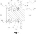
- FIG. 1 is a schematic sectional view of the hub bearing according to this embodiment of the present invention.
- Fig. 1 is a schematic sectional view obtained by cutting the hub bearing on a plane that includes a (rotary) central axis of an inner ring.
- the hub bearing 10 includes an inner ring 20, an outer ring 30 provided concentrically with the inner ring 20, and a plurality of balls 40 provided therebetween.
- the inner ring 20 and the outer ring 30 are configured to be capable of relative rotation.
- a tire (not shown) is fixed to the inner ring 20 side, and the outer ring 30 is mounted on a vehicle body side.
- the right side of Fig. 1 will be referred to as the tire side (A), and the left side will be referred to as the vehicle body side (B).
- An outward flange 21 for mounting the tire is provided on the tire side (A) of the inner ring 20.
- sealing devices 100, 200 for sealing an annular gap between the inner ring 20 and the outer ring 30 are provided in order to suppress the infiltration of foreign matter such as muddy water into the interior of the hub bearing 10 from the outside and to prevent grease (G) serving as a lubricant from leaking out of the interior.
- the sealing device 100 on the tire side (A) will also be referred to as an outer seal
- the sealing device 200 on the vehicle body side (B) will also be referred to as an inner seal.
- FIG. 2 is a schematic sectional view of the sealing device according to this embodiment of the present invention.
- a part of the inner ring 20 and a part of the outer ring 30 after installing the sealing device into the hub bearing are shown by dotted lines.
- Fig. 2 is a sectional view obtained by cutting the sealing device on a plane that includes the central axis of the sealing device.
- FIG. 3 is a schematic view showing a configuration of a slinger according to this embodiment of the present invention, wherein a sectional view obtained by cutting a part of the slinger on a plane that includes the central axis of the slinger is shown in the upper portion of the drawing, and an external view is shown in the lower portion of the drawing.
- Fig. 4 is a schematic view showing a configuration of a seal body according to this embodiment of the present invention, wherein a sectional view obtained by cutting a part of the seal body on a plane that includes the central axis of the seal body is shown in the upper portion of the drawing, and an external view is shown in the lower portion of the drawing.
- the sealing device 100 according to this embodiment can be applied as the aforementioned outer seal.
- sealing device 100 applied as the outer seal and a sealing structure that includes the sealing device 100 will be described below.
- the sealing device of the present invention is not limited to being applied to a hub bearing for an automobile, and may be employed in various applications, such as an industrial hub bearing.
- the sealing structure includes the inner ring 20, the outer ring 30 provided concentrically with the inner ring 20, and the sealing device 100 for sealing the annular gap between the inner ring 20 and the outer ring 30.
- the inner ring 20 includes a columnar surface-shaped outer peripheral surface 22, a planar end surface 23, and a curved surface 24 connecting the outer peripheral surface 22 to the end surface 23.
- the sealing device 100 is disposed in an annular space part between an annular part 31 near the tip end of the outer ring 30 on the tire side (A) and the outer peripheral surface 22, side surface 23, and curved surface 24 of the inner ring 20.
- the sealing device 100 includes a slinger 110 formed from a rigid material such as a metal, and a seal body 120.
- the slinger 110 includes a cylindrical portion 111 that is mounted on the inner ring 20, an outward flange 112 that is provided on an end of the cylindrical portion 111, and an outer ring portion 113 that extends from a radially outward part of the outward flange 112 in the central axis direction of the inner ring 20 toward the side of a sealing target space.
- the sealing target space is a space between the outer seal (the sealing device 100) and the inner seal (the sealing device 200), in which the plurality of balls 40 are arranged and a lubricant (grease) is charged.
- the side of the sealing target space relative to the sealing device 100 can also be referred to as the vehicle body side (B).
- the slinger 110 also includes a curved portion 114 provided to connect the cylindrical portion 111 to the outward flange 112.
- the cylindrical portion 111 of the slinger 110 is mounted along the outer peripheral surface 22 of the inner ring 20. Further, the outward flange 112 of the slinger 110 is mounted so as to closely contact the end surface 23 of the inner ring 20. Furthermore, the curved portion 114 of the slinger 110 is configured to closely contact the curved surface 24 of the inner ring 20. This can minimize dead space formed between the slinger 110 and the inner ring 20.
- the seal body 120 includes a reinforcing ring 121 formed from a rigid material such as a metal, and an elastic seal 122 formed from an elastomer material and provided integrally with the reinforcing ring 121, and the seal body 120 is mounted on the outer ring 30.
- the reinforcing ring 121 is configured to be mounted on the outer ring 30.
- the reinforcing ring 121 includes a cylindrical portion (a reinforcing ring cylindrical portion) 121a that is fitted to an inner peripheral surface of the annular part 31 of the outer ring 30, an outward flange (a reinforcing ring outward flange) 121b that is provided on one end of the cylindrical portion 121a, and a trunk portion 121c that extends radially inwardly from the other end of the cylindrical portion 121a.
- the seal body 120 can be obtained such that the reinforcing ring 121 and the elastic seal 122 are formed integrally therein.
- the elastic seal 122 includes a main lip 122a, an intermediate lip 122b, a side lip 122c, an auxiliary lip 122d, and an outer ring portion 122e, these components being formed integrally.
- the main lip 122a is configured to extend radially inwardly toward the sealing target space side (the vehicle body side (B)). In this embodiment, the main lip 122a is configured to contact an outer peripheral surface of the cylindrical portion 111 of the slinger 110.
- the intermediate lip 122b is provided between the main lip 122a and the side lip 122c. The intermediate lip 122b is configured to extend radially outwardly toward the opposite side (the tire side (A)) to the sealing target space, and to contact a planar end surface of the outward flange 112 of the slinger 110.
- the side lip 122c is configured to extend radially outwardly toward the opposite side (the tire side (A)) to the sealing target space, and to contact the planar end surface of the outward flange 112 of the slinger 110. Note that when the inner ring 20 and the outer ring 30 rotate relative to each other, the slinger 110 fixed to the inner ring 20 and the seal body 120 fixed to the outer ring 30 rotate relative to each other. The main lip 122a, the intermediate lip 122b, and the side lip 122c slide relative to the slinger 110.
- auxiliary lip 122d is configured to extend radially outwardly toward the opposite side (the tire side (A)) to the sealing target space, and not to contact the slinger 110.
- the outer ring portion 122e is configured such that a small annular gap is provided between the outer ring portion 122e and the outer ring portion 113 of the slinger 110. With this configuration, a labyrinth seal L is formed between the outer ring portion 113 of the slinger 110 and the outer peripheral surface side of the seal body 120.
- the labyrinth seal L is constituted by the small annular gap between the outer ring portion 122e of the seal body 120 and the outer ring portion 113 of the slinger 110, and a small annular gap between the auxiliary lip 122d of the seal body 120 and the slinger 110.
- a first annular recess 122f is formed between the side lip 122c and the intermediate lip 122b. Further, a second annular recess 122g is formed along the outer peripheral surface of the side lip 122c. In this embodiment, the second annular recess 122g is configured such that the depth thereof in the central axis direction of the inner ring 20 and toward the sealing target space side is greater than that of the first annular recess 122f.
- the second annular recess 122g is configured such that a distance from the end surface of the outward flange 112 of the slinger 110, on which the side lip 122c and the intermediate lip 122b contact each other, to the bottom of the recess is greater than in the first annular recess 122f. Accordingly, the depth of the recess of the second annular recess 122g is configured to be greater than the depth of the recess of the first annular recess 122f by d1 (see Fig. 2 ).
- the bottom of the second annular recess 122g is configured to be positioned further toward the sealing target space side in the central axis direction of the inner ring 20 than the surface of the outward flange 121b of the reinforcing ring 121 on the side to which the outer ring 30 is fitted (see a distance d2 in Fig. 2 ). Furthermore, in this embodiment, an ample step d3 is provided between the outward flange 121b of the reinforcing ring 121 and the trunk portion 121c. By providing the step d3, the depth of the second annular recess 122g can be increased.
- an improvement can be achieved in terms of suppressing the infiltration of foreign matter such as muddy water.
- the sealing functions realized by the various seal lips (the main lip 122a in particular) can be demonstrated over the long term.
- rusting of the inner ring 20 due to adherence of foreign matter such as muddy water can be suppressed.
- the durable life of the sealing device 100 can be extended. The reason why an improvement can be achieved in terms of suppressing the infiltration of foreign matter such as muddy water will be described in more detail below.
- a sectional area S1 of the second annular recess 122g is set to be at least 6 mm 2 , in contrast to a conventional structure in which the sectional area S1 is approximately 5.6 mm 2 .
- the sectional area S1 of the second annular recess 122g is defined as the sectional area of a cross-section obtained by cutting a space surrounded by the outer peripheral surface of the side lip 122c, the end surface of the outward flange 112 of the slinger 110, and an extension surface (an imaginary surface (see the dotted line in Fig. 2 )) of the inner peripheral surface of the cylindrical portion 121a of the reinforcing ring 121 on a plane that includes the central axis of the sealing device 100.
- the intermediate lip 122b similarly to the side lip 122c, is configured to contact the planar end surface of the outward flange 112.
- the intermediate lip 122b can likewise demonstrate a sealing function with more stability than when configured to contact a curved surface.
- this embodiment employs a configuration in which the labyrinth seal L is formed. As a result, the infiltration of foreign matter such as muddy water to the side lip 122c side can be suppressed.
- the main lip 122a is configured to contact the outer peripheral surface of the cylindrical portion 111 of the slinger 110. Hence, even if rust forms on the inner ring 20, the main lip 122a is not affected by the rust formed on the inner ring 20.
- the inner ring 20 is typically formed from a material having low rust resistance, whereas the material of the slinger 110 can be selected freely. Therefore, by using SUS, for example, which has high rust resistance, as the material of the slinger 110, the sealing function realized by the main lip 122a can be demonstrated with stability over the long term.
- the dead space formed between the slinger 110 and the inner ring 20 can be minimized. Accordingly, the space formed between the slinger 110 and the seal body 120 can be maximized, enabling an increase in the capacity for holding foreign matter such as muddy water. As a result, foreign matter such as muddy water can be prevented from reaching the main lip 122a. Note that since the distance by which the slinger 110 and the inner ring 20 closely contact each other also increases, an effect is also obtained in that muddy water entering between the slinger 110 and the inner ring 20 is less likely to enter the sealing target space.
- a sectional area S2 of a cross-section obtained by cutting the space surrounded by the main lip 122a and intermediate lip 122b and the slinger 110 on a plane that includes the central axis of the sealing device 100 can be set at 3 mm 2 or more, in contrast to a conventional structure in which the sectional area S2 is approximately 1 to 1.5 mm 2 .
- a plurality of means are employed in order to suppress the infiltration of foreign matter such as muddy water into the seal part formed by the main lip 122a.
- the infiltration of foreign matter such as muddy water can be suppressed synergistically.
- a plurality of means are employed in order to suppress the infiltration of foreign matter such as muddy water into the seal part formed by the main lip 122a.
- the means necessarily have to be employed.
- a configuration in which a gap is provided between the slinger 110 and the end surface 23 and curved surface 24 of the inner ring 20 can be employed.
- a configuration in which the labyrinth seal L is not provided can be employed.
- a configuration in which the outer ring portion 113 is not provided on the slinger 110 and a configuration in which the outer ring portion 122e is not provided on the seal body 120 can be employed.
- a configuration in which the main lip 122a directly contacts the outer peripheral surface of the inner ring 20 can be employed.
Landscapes
- Engineering & Computer Science (AREA)
- General Engineering & Computer Science (AREA)
- Mechanical Engineering (AREA)
- Sealing Of Bearings (AREA)
- Sealing With Elastic Sealing Lips (AREA)
Abstract
Description
- The present invention relates to a sealing device and a sealing structure.
- In a hub bearing installed in an automobile or the like, a sealing device is provided to suppress the infiltration of foreign matter such as muddy water into the interior of the bearing, and to suppress leakage of a lubricant such as grease to the outside. The sealing device is provided so as to seal an annular gap between an inner ring and an outer ring. The inner ring typically has low rust resistance, and therefore, when muddy water or the like adheres thereto so that rust forms, the sealing performance decreases.
-
- [PTL 1]
Japanese Patent Application Publication No. 2012-61875 - [PTL 2]
Japanese Patent Application Publication No. 2021-11938 - The present invention provides a sealing device and a sealing structure with which an improvement is achieved in terms of suppressing the infiltration of foreign matter such as muddy water.
- To achieve the object described above, the present invention employs the following means.
- A sealing device according to the present invention is a sealing device used in a hub bearing in order to seal an annular gap between an inner ring and an outer ring, the sealing device including:
- a slinger having a cylindrical portion that is mounted on the inner ring, and an outward flange that is provided on an end of the cylindrical portion; and
- a seal body that is mounted on the outer ring and includes a reinforcing ring and an elastic seal formed from an elastomer material and provided integrally with the reinforcing ring,
- wherein the elastic seal includes:
- a main lip;
- a side lip that extends radially outwardly and toward the opposite side to a sealing target space, and contacts the outward flange;
- an intermediate lip that is provided between the main lip and the side lip, extends radially outwardly and toward the opposite side to the sealing target space, and contacts the outward flange;
- a first annular recess formed between the side lip and the intermediate lip; and
- a second annular recess formed along an outer peripheral surface of the side lip, wherein
- the second annular recess is recessed in a central axis direction of the inner ring and toward the sealing target space side by a greater depth than the first annular recess.
- According to the present invention, by increasing the depth of the second annular recess formed along the outer peripheral surface of the side lip, the capacity for holding foreign matter such as muddy water on the outer peripheral surface side of the side lip can be increased. This can suppress the infiltration of foreign matter such as muddy water toward the intermediate lip and the main lip.
- The reinforcing ring may include a reinforcing ring cylindrical portion that is configured to be fitted to an inner peripheral surface of the outer ring, and a reinforcing ring outward flange that is provided on an end of the reinforcing ring cylindrical portion, and
the bottom of the second annular recess may be positioned further toward the sealing target space side in the central axis direction of the inner ring than a surface of the reinforcing ring outward flange on the side to which the outer ring is fitted. - The slinger may include an outer ring portion that extends from a radially outward part of the outward flange in the central axis direction of the inner ring toward the sealing target space, and
a labyrinth seal may be formed between the outer ring portion and an outer peripheral surface side of the seal body. - This can suppress the infiltration of foreign matter such as muddy water to the side lip side.
- The main lip may contact an outer peripheral surface of the cylindrical portion of the slinger.
- Thus, even when rust forms on the inner ring, the main lip is not affected by the rust formed on the inner ring.
- The side lip and the intermediate lip may contact a planar end surface of the outward flange.
- By configuring the intermediate lip and the side lip similarly in this manner so as to contact the planar end surface of the outward flange, the respective lips can demonstrate a sealing function with more stability than when configured to contact a curved surface. This can suppress the infiltration of foreign matter such as muddy water toward the main lip.
- A sealing structure according to the present invention includes an inner ring, an outer ring provided concentrically with the inner ring, and the sealing device described above, for sealing the annular gap between the inner ring and the outer ring.
- Further, a sealing structure according to the present invention includes:
- an inner ring having a columnar surface-shaped outer peripheral surface, a planar end surface, and a curved surface connecting the outer peripheral surface to the end surface;
- an outer ring provided concentrically with the inner ring; and
- a sealing device used in a hub bearing in order to seal an annular gap between the inner ring and the outer ring,
- the sealing device comprising:
- a slinger including a cylindrical portion that is mounted on the inner ring, and an outward flange that is provided on an end of the cylindrical portion; and
- a seal body that is mounted on the outer ring and includes a reinforcing ring and an elastic seal formed from an elastomer material and provided integrally with the reinforcing ring,
- wherein the elastic seal includes:
- a main lip;
- a side lip that extends radially outwardly and toward the opposite side to a sealing target space, and contacts the outward flange; and
- an intermediate lip that is provided between the main lip and the side lip, extends radially outwardly and toward the opposite side to the sealing target space, and contacts the outward flange, and
- the cylindrical portion is mounted along the outer peripheral surface of the inner ring, the outward flange is mounted so as to closely contact the end surface of the inner ring, and the slinger includes a curved portion that is provided so as to connect the cylindrical portion to the outward flange and closely contacts the curved surface of the inner ring.
- According to the present invention, dead space formed between the slinger and the inner ring can be minimized. This can maximize a space formed between the slinger and the seal body, enabling an increase in the capacity for holding foreign matter such as muddy water. This can prevent foreign matter such as muddy water from reaching the main lip.
- The sealing device may include a first annular recess formed between the side lip and the intermediate lip and a second annular recess formed along an outer peripheral surface of the side lip. The second annular recess may be recessed in a central axis direction of the inner ring and toward the sealing target space side by a greater depth than the first annular recess.
- The reinforcing ring may include a reinforcing ring cylindrical portion that is fitted to an inner peripheral surface of the outer ring, and a reinforcing ring outward flange that is provided on an end of the reinforcing ring cylindrical portion, and
the bottom of the second annular recess may be positioned further toward the sealing target space side in the central axis direction of the inner ring than a surface of the reinforcing ring outward flange on the side to which the outer ring is fitted. - The slinger may include an outer ring portion that extends from a radially outward part of the outward flange in the central axis direction of the inner ring toward the sealing target space, and
a labyrinth seal may be formed between the outer ring portion and an outer peripheral surface side of the seal body. - The main lip may contact an outer peripheral surface of the cylindrical portion of the slinger.
- Note that the configurations described above may be employed in any possible combinations.
- According to the present invention, as described above, an improvement can be achieved in terms of suppressing the infiltration of foreign matter such as muddy water.
-
- [
Fig. 1 ]
Fig. 1 is a schematic sectional view of a hub bearing according to an embodiment of the present invention. - [
Fig. 2 ]
Fig. 2 is a schematic sectional view of a sealing device according to this embodiment of the present invention. - [
Fig. 3 ]
Fig. 3 is a schematic view showing a configuration of a slinger according to this embodiment of the present invention. - [
Fig. 4 ]
Fig. 4 is a schematic view showing a configuration of a seal body according to this embodiment of the present invention. - Exemplary forms in which the invention is implemented will be described in detail below with reference to the figures on the basis of an embodiment. Note, however, that unless specifically indicated otherwise, the scope of the invention is not limited only to the dimensions, materials, shapes, relative arrangements, and so on of the constituent components described in the embodiment.
- A hub bearing to which a sealing device according to this embodiment can be applied will be described with reference to
Fig. 1. Fig. 1 is a schematic sectional view of the hub bearing according to this embodiment of the present invention.Fig. 1 is a schematic sectional view obtained by cutting the hub bearing on a plane that includes a (rotary) central axis of an inner ring. - An automobile is equipped with a
hub bearing 10. Thehub bearing 10 includes aninner ring 20, anouter ring 30 provided concentrically with theinner ring 20, and a plurality ofballs 40 provided therebetween. Theinner ring 20 and theouter ring 30 are configured to be capable of relative rotation. A tire (not shown) is fixed to theinner ring 20 side, and theouter ring 30 is mounted on a vehicle body side. Hereinafter, for convenience, the right side ofFig. 1 will be referred to as the tire side (A), and the left side will be referred to as the vehicle body side (B). Anoutward flange 21 for mounting the tire is provided on the tire side (A) of theinner ring 20. Further, sealingdevices inner ring 20 and theouter ring 30 are provided in order to suppress the infiltration of foreign matter such as muddy water into the interior of the hub bearing 10 from the outside and to prevent grease (G) serving as a lubricant from leaking out of the interior. Thesealing device 100 on the tire side (A) will also be referred to as an outer seal, and thesealing device 200 on the vehicle body side (B) will also be referred to as an inner seal. - Referring to
Figs. 2 to 4 , a sealing device and a sealing structure according to an embodiment of the present invention will be described.Fig. 2 is a schematic sectional view of the sealing device according to this embodiment of the present invention. InFig. 2 , a part of theinner ring 20 and a part of theouter ring 30 after installing the sealing device into the hub bearing are shown by dotted lines. Note thatFig. 2 is a sectional view obtained by cutting the sealing device on a plane that includes the central axis of the sealing device.Fig. 3 is a schematic view showing a configuration of a slinger according to this embodiment of the present invention, wherein a sectional view obtained by cutting a part of the slinger on a plane that includes the central axis of the slinger is shown in the upper portion of the drawing, and an external view is shown in the lower portion of the drawing.Fig. 4 is a schematic view showing a configuration of a seal body according to this embodiment of the present invention, wherein a sectional view obtained by cutting a part of the seal body on a plane that includes the central axis of the seal body is shown in the upper portion of the drawing, and an external view is shown in the lower portion of the drawing. Thesealing device 100 according to this embodiment can be applied as the aforementioned outer seal. An embodiment of thesealing device 100 applied as the outer seal and a sealing structure that includes thesealing device 100 will be described below. Note that the sealing device of the present invention is not limited to being applied to a hub bearing for an automobile, and may be employed in various applications, such as an industrial hub bearing. - The sealing structure according to this embodiment includes the
inner ring 20, theouter ring 30 provided concentrically with theinner ring 20, and thesealing device 100 for sealing the annular gap between theinner ring 20 and theouter ring 30. Theinner ring 20 includes a columnar surface-shaped outerperipheral surface 22, aplanar end surface 23, and acurved surface 24 connecting the outerperipheral surface 22 to theend surface 23. Thesealing device 100 is disposed in an annular space part between anannular part 31 near the tip end of theouter ring 30 on the tire side (A) and the outerperipheral surface 22,side surface 23, andcurved surface 24 of theinner ring 20. - The
sealing device 100 according to this embodiment includes aslinger 110 formed from a rigid material such as a metal, and aseal body 120. - The
slinger 110 includes acylindrical portion 111 that is mounted on theinner ring 20, anoutward flange 112 that is provided on an end of thecylindrical portion 111, and anouter ring portion 113 that extends from a radially outward part of theoutward flange 112 in the central axis direction of theinner ring 20 toward the side of a sealing target space. Note that in this embodiment, the sealing target space is a space between the outer seal (the sealing device 100) and the inner seal (the sealing device 200), in which the plurality ofballs 40 are arranged and a lubricant (grease) is charged. The side of the sealing target space relative to thesealing device 100 can also be referred to as the vehicle body side (B). Theslinger 110 also includes acurved portion 114 provided to connect thecylindrical portion 111 to theoutward flange 112. - In this embodiment, the
cylindrical portion 111 of theslinger 110 is mounted along the outerperipheral surface 22 of theinner ring 20. Further, theoutward flange 112 of theslinger 110 is mounted so as to closely contact theend surface 23 of theinner ring 20. Furthermore, thecurved portion 114 of theslinger 110 is configured to closely contact thecurved surface 24 of theinner ring 20. This can minimize dead space formed between theslinger 110 and theinner ring 20. - The
seal body 120 includes a reinforcingring 121 formed from a rigid material such as a metal, and anelastic seal 122 formed from an elastomer material and provided integrally with the reinforcingring 121, and theseal body 120 is mounted on theouter ring 30. - The reinforcing
ring 121 is configured to be mounted on theouter ring 30. The reinforcingring 121 includes a cylindrical portion (a reinforcing ring cylindrical portion) 121a that is fitted to an inner peripheral surface of theannular part 31 of theouter ring 30, an outward flange (a reinforcing ring outward flange) 121b that is provided on one end of thecylindrical portion 121a, and atrunk portion 121c that extends radially inwardly from the other end of thecylindrical portion 121a. By providing theelastic seal 122 by means of insert molding using the reinforcingring 121 as an insert component, for example, theseal body 120 can be obtained such that the reinforcingring 121 and theelastic seal 122 are formed integrally therein. - The
elastic seal 122 includes amain lip 122a, anintermediate lip 122b, aside lip 122c, anauxiliary lip 122d, and anouter ring portion 122e, these components being formed integrally. - The
main lip 122a is configured to extend radially inwardly toward the sealing target space side (the vehicle body side (B)). In this embodiment, themain lip 122a is configured to contact an outer peripheral surface of thecylindrical portion 111 of theslinger 110. Theintermediate lip 122b is provided between themain lip 122a and theside lip 122c. Theintermediate lip 122b is configured to extend radially outwardly toward the opposite side (the tire side (A)) to the sealing target space, and to contact a planar end surface of theoutward flange 112 of theslinger 110. Theside lip 122c is configured to extend radially outwardly toward the opposite side (the tire side (A)) to the sealing target space, and to contact the planar end surface of theoutward flange 112 of theslinger 110. Note that when theinner ring 20 and theouter ring 30 rotate relative to each other, theslinger 110 fixed to theinner ring 20 and theseal body 120 fixed to theouter ring 30 rotate relative to each other. Themain lip 122a, theintermediate lip 122b, and theside lip 122c slide relative to theslinger 110. - Further, the
auxiliary lip 122d is configured to extend radially outwardly toward the opposite side (the tire side (A)) to the sealing target space, and not to contact theslinger 110. Theouter ring portion 122e is configured such that a small annular gap is provided between theouter ring portion 122e and theouter ring portion 113 of theslinger 110. With this configuration, a labyrinth seal L is formed between theouter ring portion 113 of theslinger 110 and the outer peripheral surface side of theseal body 120. More specifically, the labyrinth seal L is constituted by the small annular gap between theouter ring portion 122e of theseal body 120 and theouter ring portion 113 of theslinger 110, and a small annular gap between theauxiliary lip 122d of theseal body 120 and theslinger 110. - In the
seal body 120 configured as described above, a firstannular recess 122f is formed between theside lip 122c and theintermediate lip 122b. Further, a secondannular recess 122g is formed along the outer peripheral surface of theside lip 122c. In this embodiment, the secondannular recess 122g is configured such that the depth thereof in the central axis direction of theinner ring 20 and toward the sealing target space side is greater than that of the firstannular recess 122f. In other words, the secondannular recess 122g is configured such that a distance from the end surface of theoutward flange 112 of theslinger 110, on which theside lip 122c and theintermediate lip 122b contact each other, to the bottom of the recess is greater than in the firstannular recess 122f. Accordingly, the depth of the recess of the secondannular recess 122g is configured to be greater than the depth of the recess of the firstannular recess 122f by d1 (seeFig. 2 ). Moreover, the bottom of the secondannular recess 122g is configured to be positioned further toward the sealing target space side in the central axis direction of theinner ring 20 than the surface of theoutward flange 121b of the reinforcingring 121 on the side to which theouter ring 30 is fitted (see a distance d2 inFig. 2 ). Furthermore, in this embodiment, an ample step d3 is provided between theoutward flange 121b of the reinforcingring 121 and thetrunk portion 121c. By providing the step d3, the depth of the secondannular recess 122g can be increased. - With the
sealing device 100 and the sealing structure including thesealing device 100 according to this embodiment, an improvement can be achieved in terms of suppressing the infiltration of foreign matter such as muddy water. As a result, the sealing functions realized by the various seal lips (themain lip 122a in particular) can be demonstrated over the long term. Moreover, rusting of theinner ring 20 due to adherence of foreign matter such as muddy water can be suppressed. As a result, the durable life of thesealing device 100 can be extended. The reason why an improvement can be achieved in terms of suppressing the infiltration of foreign matter such as muddy water will be described in more detail below. - In the
sealing device 100 used in the hub bearing, foreign matter such as muddy water adheres to theside lip 122c during use. The foreign matter flows down along the outer peripheral surface of theside lip 122c due to gravity, but a part thereof may remain on top of theside lip 122c. Overtime, the foreign matter accumulates on top of theside lip 122c such that some of the foreign matter passes through the seal part formed by theside lip 122c and infiltrates toward theintermediate lip 122b. Thereafter, due to deterioration over time, some of the foreign matter also passes through the seal part formed by theintermediate lip 122b so as to infiltrate toward themain lip 122a. When the foreign matter infiltrates the seal part formed by themain lip 122a, the sealing performance decreases. Note that theside lip 122c and theintermediate lip 122b extend radially outwardly and therefore have a function for discharging the foreign matter to the outside of the lips after the foreign matter passes through the seal parts. - In the
sealing device 100 according to this embodiment, by increasing the depth of the secondannular recess 122g (the recess toward the sealing target space side in the central axis direction of the inner ring 20), the capacity for holding foreign matter such as muddy water on the outer peripheral surface side of theside lip 122c can be increased. As a result, the infiltration of foreign matter such as muddy water toward theintermediate lip 122b and themain lip 122a can be suppressed. Note that in this embodiment, a sectional area S1 of the secondannular recess 122g is set to be at least 6 mm2, in contrast to a conventional structure in which the sectional area S1 is approximately 5.6 mm2. Note that "the sectional area S1 of the secondannular recess 122g" is defined as the sectional area of a cross-section obtained by cutting a space surrounded by the outer peripheral surface of theside lip 122c, the end surface of theoutward flange 112 of theslinger 110, and an extension surface (an imaginary surface (see the dotted line inFig. 2 )) of the inner peripheral surface of thecylindrical portion 121a of the reinforcingring 121 on a plane that includes the central axis of thesealing device 100. - Further, in this embodiment, the
intermediate lip 122b, similarly to theside lip 122c, is configured to contact the planar end surface of theoutward flange 112. Hence, theintermediate lip 122b can likewise demonstrate a sealing function with more stability than when configured to contact a curved surface. As a result, even when foreign matter such as muddy water infiltrates from the seal portion of theside lip 122c, the foreign matter can be effectively prevented from infiltrating toward themain lip 122a by theintermediate lip 122b. - Moreover, this embodiment employs a configuration in which the labyrinth seal L is formed. As a result, the infiltration of foreign matter such as muddy water to the
side lip 122c side can be suppressed. - Furthermore, in this embodiment, the
main lip 122a is configured to contact the outer peripheral surface of thecylindrical portion 111 of theslinger 110. Hence, even if rust forms on theinner ring 20, themain lip 122a is not affected by the rust formed on theinner ring 20. Theinner ring 20 is typically formed from a material having low rust resistance, whereas the material of theslinger 110 can be selected freely. Therefore, by using SUS, for example, which has high rust resistance, as the material of theslinger 110, the sealing function realized by themain lip 122a can be demonstrated with stability over the long term. - Moreover, in this embodiment, by employing a configuration in which the respective parts of the
slinger 110 closely contact the respective parts of theinner ring 20, the dead space formed between theslinger 110 and theinner ring 20 can be minimized. Accordingly, the space formed between theslinger 110 and theseal body 120 can be maximized, enabling an increase in the capacity for holding foreign matter such as muddy water. As a result, foreign matter such as muddy water can be prevented from reaching themain lip 122a. Note that since the distance by which theslinger 110 and theinner ring 20 closely contact each other also increases, an effect is also obtained in that muddy water entering between theslinger 110 and theinner ring 20 is less likely to enter the sealing target space. When muddy water enters the small gap between theslinger 110 and theinner ring 20, rust forms on the surface of theinner ring 20 that contacts theslinger 110 on the atmosphere side. Rust in this location may gradually advance from the atmosphere side toward the sealing target space side over time, leading to an increase in the amount of infiltrating muddy water. When the distance by which theslinger 110 and theinner ring 20 closely contact each other is long, it takes more time for the rust to advance from the atmosphere side to the sealing target space side, and therefore muddy water infiltration along this route can also be delayed. - In this embodiment, a sectional area S2 of a cross-section obtained by cutting the space surrounded by the
main lip 122a andintermediate lip 122b and theslinger 110 on a plane that includes the central axis of thesealing device 100 can be set at 3 mm2 or more, in contrast to a conventional structure in which the sectional area S2 is approximately 1 to 1.5 mm2. - In the
sealing device 100 and the sealing structure according to this embodiment, as described above, a plurality of means are employed in order to suppress the infiltration of foreign matter such as muddy water into the seal part formed by themain lip 122a. As a result, the infiltration of foreign matter such as muddy water can be suppressed synergistically. - In the embodiment described above, a plurality of means are employed in order to suppress the infiltration of foreign matter such as muddy water into the seal part formed by the
main lip 122a. Depending on the use environment, however, not all of the means necessarily have to be employed. - For example, when there is plenty of room to arrange the
sealing device 100, a configuration in which a gap is provided between theslinger 110 and theend surface 23 andcurved surface 24 of theinner ring 20 can be employed. Moreover, a configuration in which the labyrinth seal L is not provided can be employed. In other words, a configuration in which theouter ring portion 113 is not provided on theslinger 110 and a configuration in which theouter ring portion 122e is not provided on theseal body 120 can be employed. Furthermore, a configuration in which themain lip 122a directly contacts the outer peripheral surface of theinner ring 20 can be employed. -
- 10
- Hub bearing
- 20
- Inner ring
- 21
- Outward flange
- 22
- Outer peripheral surface
- 23
- End surface
- 24
- Curved surface
- 30
- Outer ring
- 31
- Annular part
- 40
- Ball
- 100, 200
- Sealing device
- 110
- Slinger
- 111
- Cylindrical portion
- 112
- Outward flange
- 113
- Outer ring portion
- 114
- Curved portion
- 120
- Seal body
- 121
- Reinforcing ring
- 121a
- Cylindrical portion
- 121b
- Outward flange
- 121c
- Trunk portion
- 122
- Elastic seal
- 122a
- Main lip
- 122b
- Intermediate lip
- 122c
- Side lip
- 122d
- Auxiliary lip
- 122e
- Outer ring portion
- 122f
- First annular recess
- 122g
- Second annular recess
- L
- Labyrinth seal
Claims (11)
- A sealing device used in a hub bearing in order to seal an annular gap between an inner ring and an outer ring, the sealing device comprising:a slinger having a cylindrical portion that is mounted on the inner ring, and an outward flange that is provided on an end of the cylindrical portion; anda seal body that is mounted on the outer ring and includes a reinforcing ring and an elastic seal formed from an elastomer material and provided integrally with the reinforcing ring,wherein the elastic seal includes:a main lip;a side lip that extends radially outwardly and toward the opposite side to a sealing target space, and contacts the outward flange;an intermediate lip that is provided between the main lip and the side lip, extends radially outwardly and toward the opposite side to the sealing target space, and contacts the outward flange,a first annular recess formed between the side lip and the intermediate lip; anda second annular recess formed along an outer peripheral surface of the side lip, whereinthe second annular recess is recessed in a central axis direction of the inner ring and toward the sealing target space side by a greater depth than the first annular recess.
- The sealing device according to claim 1, wherein the reinforcing ring includes a reinforcing ring cylindrical portion that is configured to be fitted to an inner peripheral surface of the outer ring, and a reinforcing ring outward flange that is provided on an end of the reinforcing ring cylindrical portion, and
the bottom of the second annular recess is positioned further toward the sealing target space side in the central axis direction of the inner ring than a surface of the reinforcing ring outward flange on the side to which the outer ring is fitted. - The sealing device according to claim 1 or 2, wherein the slinger includes an outer ring portion that extends from a radially outward part of the outward flange in the central axis direction of the inner ring toward the sealing target space, and
a labyrinth seal is formed between the outer ring portion and an outer peripheral surface side of the seal body. - The sealing device according to claim 1, 2, or 3, wherein the main lip contacts an outer peripheral surface of the cylindrical portion of the slinger.
- The sealing device according to any one of claims 1 to 4, wherein the side lip and the intermediate lip contact a planar end surface of the outward flange.
- A sealing structure comprising:an inner ring;an outer ring provided concentrically with the inner ring; andthe sealing device according to any one of claims 1 to 5, for sealing an annular gap between the inner ring and the outer ring.
- A sealing structure comprising:an inner ring having a columnar surface-shaped outer peripheral surface, a planar end surface, and a curved surface connecting the outer peripheral surface to the end surface;an outer ring provided concentrically with the inner ring; anda sealing device used in a hub bearing in order to seal an annular gap between the inner ring and the outer ring,the sealing device comprising:a slinger including a cylindrical portion that is mounted on the inner ring, and an outward flange that is provided on an end of the cylindrical portion; anda seal body that is mounted on the outer ring and includes a reinforcing ring and an elastic seal formed from an elastomer material and provided integrally with the reinforcing ring,wherein the elastic seal includes:a main lip;a side lip that extends radially outwardly and toward the opposite side to a sealing target space, and contacts the outward flange; andan intermediate lip that is provided between the main lip and the side lip, extends radially outwardly and toward the opposite side to the sealing target space, and contacts the outward flange, andthe cylindrical portion is mounted along the outer peripheral surface of the inner ring, the outward flange is mounted so as to closely contact the end surface of the inner ring, and the slinger includes a curved portion that is provided so as to connect the cylindrical portion to the outward flange and closely contacts the curved surface of the inner ring.
- The sealing structure according to claim 7, wherein the sealing device includes a first annular recess formed between the side lip and the intermediate lip and a second annular recess formed along an outer peripheral surface of the side lip, and the second annular recess is recessed in a central axis direction of the inner ring and toward the sealing target space side by a greater depth than the first annular recess.
- The sealing structure according to claim 8, wherein the reinforcing ring includes a reinforcing ring cylindrical portion that is fitted to an inner peripheral surface of the outer ring, and a reinforcing ring outward flange that is provided on an end of the reinforcing ring cylindrical portion, and
the bottom of the second annular recess is positioned further toward the sealing target space side in the central axis direction of the inner ring than a surface of the reinforcing ring outward flange on the side to which the outer ring is fitted. - The sealing structure according to claim 7, 8, or 9, wherein the slinger includes an outer ring portion that extends from a radially outward part of the outward flange in the central axis direction of the inner ring toward the sealing target space, and
a labyrinth seal is formed between the outer ring portion and an outer peripheral surface side of the seal body. - The sealing structure according to any one of claims 7 to 10, wherein the main lip contacts an outer peripheral surface of the cylindrical portion of the slinger.
Applications Claiming Priority (2)
| Application Number | Priority Date | Filing Date | Title |
|---|---|---|---|
| JP2022033412 | 2022-03-04 | ||
| PCT/JP2023/006759 WO2023167103A1 (en) | 2022-03-04 | 2023-02-24 | Sealing device and sealing structure |
Publications (2)
| Publication Number | Publication Date |
|---|---|
| EP4488538A1 true EP4488538A1 (en) | 2025-01-08 |
| EP4488538A4 EP4488538A4 (en) | 2025-07-16 |
Family
ID=87883648
Family Applications (1)
| Application Number | Title | Priority Date | Filing Date |
|---|---|---|---|
| EP23763362.3A Withdrawn EP4488538A4 (en) | 2022-03-04 | 2023-02-24 | SEALING DEVICE AND SEALING STRUCTURE |
Country Status (6)
| Country | Link |
|---|---|
| US (1) | US12442418B2 (en) |
| EP (1) | EP4488538A4 (en) |
| JP (1) | JPWO2023167103A1 (en) |
| KR (1) | KR20240101851A (en) |
| CN (1) | CN118434980A (en) |
| WO (1) | WO2023167103A1 (en) |
Family Cites Families (25)
| Publication number | Priority date | Publication date | Assignee | Title |
|---|---|---|---|---|
| JP2012061875A (en) | 2010-09-14 | 2012-03-29 | Ntn Corp | Bearing device for wheel |
| JP5778238B2 (en) * | 2013-11-18 | 2015-09-16 | Nok株式会社 | Manufacturing method of sealing device |
| JP6466082B2 (en) | 2014-04-30 | 2019-02-06 | 内山工業株式会社 | Bearing sealing device |
| JP6748400B2 (en) * | 2014-07-01 | 2020-09-02 | 内山工業株式会社 | Sealing device |
| JP2017036740A (en) * | 2015-08-06 | 2017-02-16 | 光洋シーリングテクノ株式会社 | Sealing device |
| KR20180033279A (en) * | 2015-09-01 | 2018-04-02 | 엔오케이 가부시키가이샤 | Sealing device |
| EP3339693B1 (en) * | 2015-10-09 | 2020-06-10 | Nok Corporation | Sealing apparatus |
| JP2017124695A (en) * | 2016-01-13 | 2017-07-20 | 株式会社ジェイテクト | Vehicular bearing device |
| JP2017137973A (en) * | 2016-02-05 | 2017-08-10 | 光洋シーリングテクノ株式会社 | Hub unit sealing device |
| JP6658216B2 (en) | 2016-03-31 | 2020-03-04 | 株式会社ジェイテクト | Wheel bearing device |
| JP6686692B2 (en) * | 2016-05-18 | 2020-04-22 | 株式会社ジェイテクト | Wheel bearing device |
| CN109416079B (en) | 2016-06-20 | 2021-02-09 | Nok株式会社 | Sealing means |
| JP2018054095A (en) * | 2016-09-30 | 2018-04-05 | 内山工業株式会社 | Seal |
| JP7024994B2 (en) * | 2017-10-06 | 2022-02-24 | 内山工業株式会社 | Sealing device |
| JP2019138399A (en) | 2018-02-13 | 2019-08-22 | 株式会社ジェイテクト | Sealing device and assembling method of sealing device |
| JP7437723B2 (en) * | 2018-07-31 | 2024-02-26 | 内山工業株式会社 | sealing device |
| JP7186039B2 (en) * | 2018-08-28 | 2022-12-08 | 光洋シーリングテクノ株式会社 | sealing device |
| JP7164401B2 (en) | 2018-11-01 | 2022-11-01 | 光洋シーリングテクノ株式会社 | sealing device |
| JP7249008B2 (en) | 2018-11-13 | 2023-03-30 | 内山工業株式会社 | sealing device |
| EP3982016A4 (en) | 2019-06-05 | 2023-06-28 | NOK Corporation | Sealing device |
| JP7342459B2 (en) | 2019-07-03 | 2023-09-12 | 株式会社ジェイテクト | rolling bearing device |
| JP7355365B2 (en) | 2019-07-09 | 2023-10-03 | 内山工業株式会社 | sealing device |
| JP7228051B2 (en) * | 2019-09-13 | 2023-02-22 | Nok株式会社 | Sealed structure |
| DE102020002878B3 (en) * | 2020-05-13 | 2021-08-05 | Nsk Deutschland Gmbh | Wheel bearing device |
| JP2024011870A (en) * | 2022-07-15 | 2024-01-25 | 内山工業株式会社 | sealing device |
-
2023
- 2023-02-24 EP EP23763362.3A patent/EP4488538A4/en not_active Withdrawn
- 2023-02-24 US US18/717,169 patent/US12442418B2/en active Active
- 2023-02-24 KR KR1020247019686A patent/KR20240101851A/en active Pending
- 2023-02-24 WO PCT/JP2023/006759 patent/WO2023167103A1/en not_active Ceased
- 2023-02-24 JP JP2024504660A patent/JPWO2023167103A1/ja active Pending
- 2023-02-24 CN CN202380015313.1A patent/CN118434980A/en active Pending
Also Published As
| Publication number | Publication date |
|---|---|
| US12442418B2 (en) | 2025-10-14 |
| JPWO2023167103A1 (en) | 2023-09-07 |
| WO2023167103A1 (en) | 2023-09-07 |
| CN118434980A (en) | 2024-08-02 |
| US20250043826A1 (en) | 2025-02-06 |
| KR20240101851A (en) | 2024-07-02 |
| EP4488538A4 (en) | 2025-07-16 |
Similar Documents
| Publication | Publication Date | Title |
|---|---|---|
| US20200392999A1 (en) | Wheel bearing arrangement having a rotational axis | |
| EP3339693B1 (en) | Sealing apparatus | |
| CN103348153B (en) | Labyrinth seal for radial rolling bearing with radial flange | |
| CN112901663B (en) | Sealing device | |
| US8146930B2 (en) | Wheel assembly with bearing cap having a seal | |
| CN102667192B (en) | Rolling bearing system with radial shaft seal ring | |
| KR20130098302A (en) | Sealing assembly for a rolling bearing | |
| US20120207417A1 (en) | Non-contact sealing ring and sealing arrangement | |
| US11193543B2 (en) | Sealing arrangement for a wheel bearing | |
| US20090322032A1 (en) | Sealing device | |
| US20150071581A1 (en) | Preassembled insertable roller bearing unit | |
| US20080292231A1 (en) | Sealing Device | |
| EP2868938B1 (en) | Wheel bearing device | |
| CN105452692A (en) | Seals with oil deflectors for rolling bearings | |
| US20200292001A1 (en) | Sealing device and rolling bearing device | |
| CN114635915B (en) | Sealing device | |
| US20120189237A1 (en) | Suspension thrust bearing device | |
| WO2016088782A1 (en) | Slide bearing and strut-type suspension | |
| WO2012049867A1 (en) | Oil seal | |
| US12442418B2 (en) | Sealing device and sealing structure | |
| US12234912B2 (en) | Bearing device for vehicle wheel | |
| US20210025453A1 (en) | Sealing structure and rolling bearing device having the sealing structure | |
| US6953193B2 (en) | Sealing apparatus | |
| JP2018080756A (en) | Rolling bearing with seal | |
| CN214742753U (en) | Novel deep groove ball bearing |
Legal Events
| Date | Code | Title | Description |
|---|---|---|---|
| STAA | Information on the status of an ep patent application or granted ep patent |
Free format text: STATUS: THE INTERNATIONAL PUBLICATION HAS BEEN MADE |
|
| PUAI | Public reference made under article 153(3) epc to a published international application that has entered the european phase |
Free format text: ORIGINAL CODE: 0009012 |
|
| STAA | Information on the status of an ep patent application or granted ep patent |
Free format text: STATUS: REQUEST FOR EXAMINATION WAS MADE |
|
| 17P | Request for examination filed |
Effective date: 20240620 |
|
| AK | Designated contracting states |
Kind code of ref document: A1 Designated state(s): AL AT BE BG CH CY CZ DE DK EE ES FI FR GB GR HR HU IE IS IT LI LT LU LV MC ME MK MT NL NO PL PT RO RS SE SI SK SM TR |
|
| DAV | Request for validation of the european patent (deleted) | ||
| DAX | Request for extension of the european patent (deleted) | ||
| A4 | Supplementary search report drawn up and despatched |
Effective date: 20250616 |
|
| RIC1 | Information provided on ipc code assigned before grant |
Ipc: F16C 33/78 20060101AFI20250610BHEP Ipc: F16C 33/80 20060101ALI20250610BHEP Ipc: F16J 15/3232 20160101ALI20250610BHEP Ipc: F16J 15/447 20060101ALI20250610BHEP |
|
| STAA | Information on the status of an ep patent application or granted ep patent |
Free format text: STATUS: THE APPLICATION HAS BEEN WITHDRAWN |
|
| 18W | Application withdrawn |
Effective date: 20251219 |