EP4488526A1 - Compressor - Google Patents
Compressor Download PDFInfo
- Publication number
- EP4488526A1 EP4488526A1 EP23791949.3A EP23791949A EP4488526A1 EP 4488526 A1 EP4488526 A1 EP 4488526A1 EP 23791949 A EP23791949 A EP 23791949A EP 4488526 A1 EP4488526 A1 EP 4488526A1
- Authority
- EP
- European Patent Office
- Prior art keywords
- seal member
- case
- ring
- face
- refrigerant
- Prior art date
- Legal status (The legal status is an assumption and is not a legal conclusion. Google has not performed a legal analysis and makes no representation as to the accuracy of the status listed.)
- Pending
Links
Images


Classifications
-
- F—MECHANICAL ENGINEERING; LIGHTING; HEATING; WEAPONS; BLASTING
- F04—POSITIVE - DISPLACEMENT MACHINES FOR LIQUIDS; PUMPS FOR LIQUIDS OR ELASTIC FLUIDS
- F04B—POSITIVE-DISPLACEMENT MACHINES FOR LIQUIDS; PUMPS
- F04B39/00—Component parts, details, or accessories, of pumps or pumping systems specially adapted for elastic fluids, not otherwise provided for in, or of interest apart from, groups F04B25/00 - F04B37/00
- F04B39/12—Casings; Cylinders; Cylinder heads; Fluid connections
- F04B39/121—Casings
-
- F—MECHANICAL ENGINEERING; LIGHTING; HEATING; WEAPONS; BLASTING
- F04—POSITIVE - DISPLACEMENT MACHINES FOR LIQUIDS; PUMPS FOR LIQUIDS OR ELASTIC FLUIDS
- F04B—POSITIVE-DISPLACEMENT MACHINES FOR LIQUIDS; PUMPS
- F04B39/00—Component parts, details, or accessories, of pumps or pumping systems specially adapted for elastic fluids, not otherwise provided for in, or of interest apart from, groups F04B25/00 - F04B37/00
-
- F—MECHANICAL ENGINEERING; LIGHTING; HEATING; WEAPONS; BLASTING
- F04—POSITIVE - DISPLACEMENT MACHINES FOR LIQUIDS; PUMPS FOR LIQUIDS OR ELASTIC FLUIDS
- F04C—ROTARY-PISTON, OR OSCILLATING-PISTON, POSITIVE-DISPLACEMENT MACHINES FOR LIQUIDS; ROTARY-PISTON, OR OSCILLATING-PISTON, POSITIVE-DISPLACEMENT PUMPS
- F04C18/00—Rotary-piston pumps specially adapted for elastic fluids
- F04C18/02—Rotary-piston pumps specially adapted for elastic fluids of arcuate-engagement type, i.e. with circular translatory movement of co-operating members, each member having the same number of teeth or tooth-equivalents
- F04C18/0207—Rotary-piston pumps specially adapted for elastic fluids of arcuate-engagement type, i.e. with circular translatory movement of co-operating members, each member having the same number of teeth or tooth-equivalents both members having co-operating elements in spiral form
- F04C18/0215—Rotary-piston pumps specially adapted for elastic fluids of arcuate-engagement type, i.e. with circular translatory movement of co-operating members, each member having the same number of teeth or tooth-equivalents both members having co-operating elements in spiral form where only one member is moving
-
- F—MECHANICAL ENGINEERING; LIGHTING; HEATING; WEAPONS; BLASTING
- F04—POSITIVE - DISPLACEMENT MACHINES FOR LIQUIDS; PUMPS FOR LIQUIDS OR ELASTIC FLUIDS
- F04C—ROTARY-PISTON, OR OSCILLATING-PISTON, POSITIVE-DISPLACEMENT MACHINES FOR LIQUIDS; ROTARY-PISTON, OR OSCILLATING-PISTON, POSITIVE-DISPLACEMENT PUMPS
- F04C23/00—Combinations of two or more pumps, each being of rotary-piston or oscillating-piston type, specially adapted for elastic fluids; Pumping installations specially adapted for elastic fluids; Multi-stage pumps specially adapted for elastic fluids
- F04C23/008—Hermetic pumps
-
- F—MECHANICAL ENGINEERING; LIGHTING; HEATING; WEAPONS; BLASTING
- F04—POSITIVE - DISPLACEMENT MACHINES FOR LIQUIDS; PUMPS FOR LIQUIDS OR ELASTIC FLUIDS
- F04C—ROTARY-PISTON, OR OSCILLATING-PISTON, POSITIVE-DISPLACEMENT MACHINES FOR LIQUIDS; ROTARY-PISTON, OR OSCILLATING-PISTON, POSITIVE-DISPLACEMENT PUMPS
- F04C27/00—Sealing arrangements in rotary-piston pumps specially adapted for elastic fluids
-
- F—MECHANICAL ENGINEERING; LIGHTING; HEATING; WEAPONS; BLASTING
- F04—POSITIVE - DISPLACEMENT MACHINES FOR LIQUIDS; PUMPS FOR LIQUIDS OR ELASTIC FLUIDS
- F04C—ROTARY-PISTON, OR OSCILLATING-PISTON, POSITIVE-DISPLACEMENT MACHINES FOR LIQUIDS; ROTARY-PISTON, OR OSCILLATING-PISTON, POSITIVE-DISPLACEMENT PUMPS
- F04C27/00—Sealing arrangements in rotary-piston pumps specially adapted for elastic fluids
- F04C27/001—Radial sealings for working fluid
-
- F—MECHANICAL ENGINEERING; LIGHTING; HEATING; WEAPONS; BLASTING
- F04—POSITIVE - DISPLACEMENT MACHINES FOR LIQUIDS; PUMPS FOR LIQUIDS OR ELASTIC FLUIDS
- F04C—ROTARY-PISTON, OR OSCILLATING-PISTON, POSITIVE-DISPLACEMENT MACHINES FOR LIQUIDS; ROTARY-PISTON, OR OSCILLATING-PISTON, POSITIVE-DISPLACEMENT PUMPS
- F04C27/00—Sealing arrangements in rotary-piston pumps specially adapted for elastic fluids
- F04C27/008—Sealing arrangements in rotary-piston pumps specially adapted for elastic fluids for other than working fluid, i.e. the sealing arrangements are not between working chambers of the machine
-
- F—MECHANICAL ENGINEERING; LIGHTING; HEATING; WEAPONS; BLASTING
- F04—POSITIVE - DISPLACEMENT MACHINES FOR LIQUIDS; PUMPS FOR LIQUIDS OR ELASTIC FLUIDS
- F04C—ROTARY-PISTON, OR OSCILLATING-PISTON, POSITIVE-DISPLACEMENT MACHINES FOR LIQUIDS; ROTARY-PISTON, OR OSCILLATING-PISTON, POSITIVE-DISPLACEMENT PUMPS
- F04C29/00—Component parts, details or accessories of pumps or pumping installations, not provided for in groups F04C18/00 - F04C28/00
-
- F—MECHANICAL ENGINEERING; LIGHTING; HEATING; WEAPONS; BLASTING
- F04—POSITIVE - DISPLACEMENT MACHINES FOR LIQUIDS; PUMPS FOR LIQUIDS OR ELASTIC FLUIDS
- F04C—ROTARY-PISTON, OR OSCILLATING-PISTON, POSITIVE-DISPLACEMENT MACHINES FOR LIQUIDS; ROTARY-PISTON, OR OSCILLATING-PISTON, POSITIVE-DISPLACEMENT PUMPS
- F04C29/00—Component parts, details or accessories of pumps or pumping installations, not provided for in groups F04C18/00 - F04C28/00
- F04C29/02—Lubrication; Lubricant separation
-
- F—MECHANICAL ENGINEERING; LIGHTING; HEATING; WEAPONS; BLASTING
- F04—POSITIVE - DISPLACEMENT MACHINES FOR LIQUIDS; PUMPS FOR LIQUIDS OR ELASTIC FLUIDS
- F04C—ROTARY-PISTON, OR OSCILLATING-PISTON, POSITIVE-DISPLACEMENT MACHINES FOR LIQUIDS; ROTARY-PISTON, OR OSCILLATING-PISTON, POSITIVE-DISPLACEMENT PUMPS
- F04C2210/00—Fluid
- F04C2210/26—Refrigerants with particular properties, e.g. HFC-134a
Definitions
- the present disclosure relates to a compressor.
- a seal member such as an O-ring may be provided between one case and another case to ensure sealing performance between the cases.
- Patent Literature 1 two O-rings aligned in the axis direction are provided between one case and another case.
- a seal member arranged at a position that is likely to be subjected to contact with the refrigerant is required to have refrigerant resistance and/or oil resistance, but some seal members that meet these requirements exhibit reduced sealing performance at low temperatures (when exposed to an environment at a temperature of -20°C or lower, for example).
- the present disclosure has been made in view of such circumstances and intends to provide a compressor that can maintain sealing performance at low temperatures.
- the compressor of the present disclosure employs the following solution.
- a compressor includes: a cylindrical main case surrounding a compression mechanism about an axis, the compression mechanism being configured to compress a refrigerant; a sub-case closing an opening of the main case in a direction of the axis, fitted to an inner circumferential face or an outer circumferential face of the main case, and defining a space between the main case and the sub-case, the refrigerant being introduced to the space; an annular first seal member provided about the axis at a facing portion where the main case and the sub-case fitted to each other face each other in a plane; and an annular second seal member provided about the axis in the facing portion, the first seal member is provided at a position closer to a starting point on the space side of the facing portion than the second seal member, the first seal member has better refrigerant resistance and/or oil resistance than the second seal member, and the second seal member has better sealing performance than the first seal member at a temperature of -20°C or lower.
- a compressor 10 is an apparatus to compress a refrigerant (for example, R1234yf) containing a refrigeration oil (for example, POE oil).
- a refrigerant for example, R1234yf
- a refrigeration oil for example, POE oil
- the compressor 10 uses, as an example of the compressor 10, a scroll compressor in which a compression mechanism 200 and an electric motor 400 serving as a driving unit are accommodated in the internal space of a casing 100 that is an enclosed space, but the compressor 10 may be a so-called open-type scroll compressor in which the driving unit is arranged outside the enclosed space.
- the compressor 10 includes the casing 100, the compression mechanism 200, a crankshaft 310, and the electric motor 400.
- the casing 100 has a motor case (main case) 110, an upper case 120, and a lower case (sub-case) 130.
- the motor case 110 is a cylindrical member extending in the direction of an axis X and opened at both ends.
- the motor case 110 surrounds the compression mechanism 200, the crankshaft 310, and the electric motor 400 about the axis X.
- the upper case 120 is a member that closes one opening of the motor case 110.
- the upper case 120 is fixed to the motor case 110 by a bolt 530.
- the lower case 130 is a member that closes the other opening (hereinafter referred to as "opening 111") of the motor case 110.
- the lower case 130 is fixed to the motor case 110 by a bolt (not illustrated).
- the detailed configuration of a portion where the motor case 110 and the lower case 130 are fitted to each other will be described later.
- An inverter cover 140 is attached to the lower case 130 by a screw 540.
- An inverter (not illustrated) is accommodated in a space defined by the lower case 130 and the inverter cover 140.
- the compression mechanism 200 In an enclosed space defined by the casing 100 (the motor case 110, the upper case 120, and the lower case 130) configured as described above, the compression mechanism 200, the crankshaft 310, the electric motor 400, and various other components are accommodated.
- the compression mechanism 200 is a mechanism that compresses a low-pressure gas refrigerant taken in from outside of the casing 100 through a suction port 116.
- the compression mechanism 200 has a fixed scroll 210 and an orbiting scroll 220.
- the fixed scroll 210 is a member having a fixed side end plate and a spiral fixed side wall body erected from the end plate.
- the fixed scroll 210 is fixed to the upper case 120 by a bolt 550. Further, the outer circumferential face of the fixed side end plate of the fixed scroll 210 is in contact with the inner circumferential face of the motor case 110 and the inner circumferential face of the upper case 120 while maintaining its sealing performance. Accordingly, the enclosed space inside the casing 100 is divided into an accommodation chamber C1 which is defined by the fixed scroll 210, the motor case 110, and the lower case 130 and a discharge chamber C2 which is defined by the fixed scroll 210 and the upper case 120.
- sealing performance between the fixed scroll 210 and the motor case 110 and the sealing performance between the fixed scroll 210 and the upper case 120 are ensured by O-rings, for example.
- the orbiting scroll 220 is a member having an orbiting side end plate and a spiral orbiting side wall body erected from the end plate.
- the orbiting scroll 220 is configured to perform revolution movement with respect to the fixed scroll 210 by the crankshaft 310 rotated about the axis X (in detail, a crankpin 312 revolved about the axis X) and a known anti-rotation mechanism.
- Respective wall bodies of the fixed scroll 210 and the orbiting scroll 220 are engaged with each other, and thereby the fixed scroll 210 and the orbiting scroll 220 form a compression chamber C3.
- the crankshaft 310 is a member for transmitting driving force from the electric motor 400 to the orbiting scroll 220.
- the crankshaft 310 has a shaft body 311 and the crankpin 312.
- the shaft body 311 is a shaft-like member extending along the axis X.
- the shaft body 311 is driven and rotated about the axis X by the electric motor 400.
- the shaft body 311 is supported rotatably about the axis X by a main bearing 510, which is arranged on the upper case 120 side and fixed to the motor case 110, and by a sub-bearing 520, which is arranged on the lower case 130 side and fixed to the lower case 130.
- the crankpin 312 is a shaft-like member provided at an end on the upper case 120 side of the shaft body 311.
- the crankpin 312 extends along another axis eccentric from the axis X. Thus, when the shaft body 311 is rotated about the axis X, the crankpin 312 is revolved about the axis X.
- crankpin 312 is connected via a bearing 222 to a boss part 221 formed in the orbiting scroll 220.
- the compressor 10 configured as described above is driven as follows.
- the shaft body 311 of the crankshaft 310 is driven and rotated about the axis X by the electric motor 400, and thereby the orbiting scroll 220 connected to the crankpin 312 is driven.
- a gas refrigerant taken into the accommodation chamber C1 on the lower case 130 side via the suction port 116 passes through a refrigerant passage or the like formed between the inner circumferential face of the motor case 110 and the outer circumferential face of the electric motor 400 (stator), and the gas refrigerant is guided to the accommodation chamber C1 on the compression mechanism 200 side.
- the refrigerant guided to the accommodation chamber C1 on the compression mechanism 200 side is taken into the compression chamber C3.
- the compression chamber C3 is configured so that the volume thereof is gradually reduced in accordance with the revolution movement of the orbiting scroll 220, and thus the gas refrigerant is compressed accordingly.
- the compressed high-temperature high-pressure gas refrigerant is guided to the discharge chamber C2 via a discharge port 211a formed in the approximate center of the fixed side end plate of the fixed scroll 210 and the discharge valve (not illustrated) provided at the outlet of the discharge port 211a.
- the gas refrigerant guided to the discharge chamber C2 is discharged to outside of the compressor 10 via the discharge port (not illustrated) provided in the upper case 120.
- annular protruding portion 131 is formed in the lower case 130.
- the annular protruding portion 131 is a portion formed in the lower case 130 facing the opening 111 of the motor case 110.
- the annular protruding portion 131 protrudes in the direction of the axis X, is formed in an annular shape about the axis X, and is fitted to the inner circumferential face of the opening 111.
- the outer diameter of the annular protruding portion 131 corresponds to the inner diameter of the opening 111.
- two seal members are provided in any range of a portion where the motor case 110 and the lower case 130 face each other in a plane.
- the portion means a portion where a portion on the opening 111 side of the motor case 110 and the annular protruding portion 131 of the lower case 130 face each other in a plane (hereinafter referred to as a "facing portion L").
- the first O-ring 151 is provided in a first annular groove 133 formed in the outer circumferential face of the annular protruding portion 131.
- the second O-ring 152 is provided in a second annular groove 134 formed in the outer circumferential face of the annular protruding portion 131.
- first O-ring 151 and the second O-ring 152 being assembled into the compressor 10 are in close contact with the motor case 110 and lower case 130, respectively, and are compressed and squeezed between the motor case 110 and lower case 130.
- the first annular groove 133 is formed at a position closer to a starting point Ls of the facing portion L than the second annular groove 134 (a position away from an end point Le of the facing portion L).
- the first O-ring 151 is provided at a position closer to the starting point Ls of the facing portion L than the second O-ring 152 (a position away from the end point Le of the facing portion L).
- the starting point Ls of the facing portion L is located on an end face 131a side of the annular protruding portion 131.
- the first annular groove 133 is formed at a position closer to the end face 131a of the annular protruding portion 131 than the second annular groove 134.
- the refrigerant will first come into contact with the first O-ring 151. Then, only if the gas refrigerant passes between the first O-ring 151 and the inner circumferential face of the motor case 110, the refrigerant will come into contact with the second O-ring 152.
- the first O-ring 151 to be employed is an O-ring having better refrigerant resistance and/or oil resistance than the second O-ring 152.
- refrigerant resistance is evaluated by an immersion test using a refrigerant (R1234yf) (JIS K 6258, "Rubber, vulcanized or thermoplastic-Determination of the effect of liquids").
- R1234yf refrigerant
- JIS K 6258 "Rubber, vulcanized or thermoplastic-Determination of the effect of liquids”
- the refrigerant resistance is evaluated by a foaming test in addition to the immersion test.
- the foaming test is a test to immerse the O-ring in a refrigerant, then heat the O-ring with air, and cut ten portions out of the O-ring to see if a crack is present in the cross-section.
- the sealing performance is evaluated by a TR test (JIS K 6261, "Rubber, vulcanized or thermoplastic-Determination of low-temperature properties"). Specifically, the sealing performance is evaluated based on a TR10 value (a temperature at which the shrinkage rate is 10%). The lower this temperature is, the better the sealing performance at low temperatures is. Note that, when an O-ring is used at a temperature lower than the TR10 value, the sealing performance may not be ensured due to a reduction in the rubber elasticity of the O-ring.
- An example of the material of the first O-ring 151 selected based on the above evaluation is HNRB, and an example of the material of the second O-ring 152 selected based on the above evaluation is EPDM.
- the first O-ring 151 and the second O-ring 152 can be easily visibly distinguished from each other.
- the compressor 10 includes: the annular first O-ring 151 provided about the axis X at a facing portion L where the motor case 110 and the lower case 130 fitted to each other face each other in a plane; and the annular second O-ring 152 provided about the axis X in the facing portion L, the first O-ring 151 is provided at a position closer to the starting point Ls of the facing portion L than the second O-ring 152, the first O-ring 151 has better refrigerant resistance and/or oil resistance than the second O-ring 152, and the second O-ring 152 has better sealing performance than the first O-ring 151 at a temperature of -20°C or lower.
- the second O-ring 152 has lower refrigerant resistance and/or oil resistance than the first O-ring 151, the second O-ring 152 is less likely to be deteriorated by the refrigerant (less likely to be affected by the refrigerant). This is because only a small amount of the refrigerant passes by the first O-ring 151, which has better refrigerant resistance and/or oil resistance and exhibits a certain level of sealing performance while having lower sealing performance at low temperatures than the second O-ring 152. In short, this is because only a small amount of a refrigerant may come into contact with the second O-ring 152.
- the combination of the first O-ring 151 and the second O-ring 152 whose materials differ from each other enables sealing performance at low temperatures to be maintained for a long period of time.
- first O-ring 151 and the second O-ring 152 can prevent incorrect assembly of respective O-rings.
- the second O-ring 152 may be provided in an end face 111a of the opening 111 of the motor case 110.
- the inner circumferential face of the lower case 130 may be fitted to the outer circumferential face of the motor case 110.
- a first annular groove 113 and the second annular groove 114 are formed in the outer circumferential face in the portion on the end face 111a side of the motor case 110.
- the starting point Ls of the facing portion L is located on the end face 111a side of the opening 111.
- the first annular groove 133 is formed at a position closer to the end face 111a of the opening 111 than the second annular groove 134.
- the first O-ring 151 is provided at a position closer to the end face 111a of the opening 111 than the second O-ring 152.
- the second O-ring 152 may be provided in a chamfer 111b connected to the end face 111a of the motor case 110.
- the chamfer 111b is a part of the inner circumferential face of the motor case 110.
- the first annular groove 133 is formed in the outer circumferential face of the annular protruding portion 131, and the chamfer 111b corresponds to the second annular groove 114 or the second annular groove 134.
- a component in which annular grooves or the like provided with two O-rings are formed can be arbitrarily selected from the motor case 110 and the lower case 130.
- annular grooves may be formed in the end face 111a of the motor case 110 and/or the face of the lower case 130 facing the end face 111a, and thereby two O-rings may be provided in these two annular grooves.
- the compressor according to the present embodiment as described above is understood as follows, for example.
- the compressor (10) includes: a cylindrical main case (110) surrounding a compression mechanism (200) about an axis (X), the compression mechanism being configured to compress a refrigerant; a sub-case (130) closing an opening (111) of the main case in a direction of the axis, fitted to an inner circumferential face or an outer circumferential face of the main case, and defining a space (C1) between the main case and the sub-case, the refrigerant being introduced to the space; an annular first seal member (151) provided about the axis at a facing portion (L) where the main case and the sub-case fitted to each other face each other in a plane; and an annular second seal member (152) provided about the axis in the facing portion, the first seal member is provided at a position closer to a starting point (Ls) on the space side of the facing portion than the second seal member, the first seal member has better refrigerant resistance and/or oil resistance than the second seal member, and the second seal member has
- the compressor includes: a annular first seal member provided about the axis at a facing portion where the main case and the sub-case fitted to each other face each other in a plane; and an annular second seal member provided about the axis in the facing portion, the first seal member is provided at a position closer to a starting point on the space side of the facing portion than the second seal member, the first seal member has better refrigerant resistance and/or oil resistance than the second seal member, and the second seal member has better sealing performance than the first seal member at a temperature of -20°C or lower.
- the first seal member which is provided at a position that is likely to be subjected to contact with the refrigerant, makes it possible to ensure a certain level of sealing performance while suppressing deterioration due to the refrigerant (containing lubricating oil) because of the excellent refrigerant resistance and/or oil resistance of the first seal member, and the second seal member makes it possible to ensure high sealing performance even in an environment at a temperature of -20°C because of the excellent sealing performance at low temperatures of the second seal member.
- the second seal member has lower refrigerant resistance and/or oil resistance than the first seal member
- the second seal member is less likely to be deteriorated by the refrigerant (less likely to be affected by the refrigerant). This is because only a small amount of the refrigerant passes by the first seal member, which has better refrigerant resistance and/or oil resistance and exhibits a certain level of sealing performance while having lower sealing performance at low temperatures than the second seal member. In short, this is because only a small amount of a refrigerant may come into contact with the second seal member.
- the first seal member may be arranged to be in contact with the inner circumferential face or the outer circumferential face of the main case, and the second seal member may be arranged to be in contact with the inner circumferential face or the outer circumferential face of the main case.
- the first seal member is arranged to be in contact with the inner circumferential face or the outer circumferential face of the main case
- the second seal member is arranged to be in contact with the inner circumferential face or the outer circumferential face of the main case.
- the first seal member is arranged to be in contact with the inner circumferential face or the outer circumferential face of the main case
- the second seal member is arranged to be in contact with an opening end face of the main case.
- the first seal member may be arranged to be in contact with an opening end face of the main case, and the second seal member may be arranged to be in contact with the opening end face of the main case.
- the first seal member is arranged to be in contact with an opening end face of the main case, and the second seal member is arranged to be in contact with the opening end face of the main case.
- the seal can be ensured with the opening end face of the main case.
- the first seal member and the second seal member differ in color from each other, and thus incorrect assembly of respective seal members can be prevented.
Landscapes
- Engineering & Computer Science (AREA)
- Mechanical Engineering (AREA)
- General Engineering & Computer Science (AREA)
- Compressor (AREA)
- Applications Or Details Of Rotary Compressors (AREA)
Abstract
Description
- The present disclosure relates to a compressor.
- For electric compressors in which one casing is formed of a plurality of cases, a seal member such as an O-ring may be provided between one case and another case to ensure sealing performance between the cases.
- For example, in Patent Literature 1, two O-rings aligned in the axis direction are provided between one case and another case.
- [PTL 1]
Japanese Patent Application Laid-Open No. 2020-143650 - A seal member arranged at a position that is likely to be subjected to contact with the refrigerant is required to have refrigerant resistance and/or oil resistance, but some seal members that meet these requirements exhibit reduced sealing performance at low temperatures (when exposed to an environment at a temperature of -20°C or lower, for example).
- The present disclosure has been made in view of such circumstances and intends to provide a compressor that can maintain sealing performance at low temperatures.
- To solve the above problem, the compressor of the present disclosure employs the following solution.
- A compressor according to one aspect of the present disclosure includes: a cylindrical main case surrounding a compression mechanism about an axis, the compression mechanism being configured to compress a refrigerant; a sub-case closing an opening of the main case in a direction of the axis, fitted to an inner circumferential face or an outer circumferential face of the main case, and defining a space between the main case and the sub-case, the refrigerant being introduced to the space; an annular first seal member provided about the axis at a facing portion where the main case and the sub-case fitted to each other face each other in a plane; and an annular second seal member provided about the axis in the facing portion, the first seal member is provided at a position closer to a starting point on the space side of the facing portion than the second seal member, the first seal member has better refrigerant resistance and/or oil resistance than the second seal member, and the second seal member has better sealing performance than the first seal member at a temperature of -20°C or lower.
- According to the present disclosure, it is possible to maintain sealing performance at low temperatures.
-
- [
Fig. 1 ]
Fig. 1 is a longitudinal sectional view of a compressor according to one form of the present disclosure. - [
Fig. 2 ]
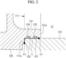
Fig. 2 is a partial enlarged view of the part A illustrated inFig. 1 . - [
Fig. 3 ]
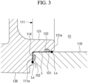
Fig. 3 illustrates a modified example 1 of the part A illustrated inFig. 1 . - [
Fig. 4 ]
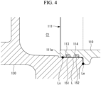
Fig. 4 illustrates a modified example 2 of the part A illustrated inFig. 1 . - [
Fig. 5 ]
Fig. 5 illustrates a modified example 3 of the part A illustrated inFig. 1 . - A compressor according to one embodiment of the present disclosure will be described below with reference to the drawings.
- A
compressor 10 is an apparatus to compress a refrigerant (for example, R1234yf) containing a refrigeration oil (for example, POE oil). - Note that the following description uses, as an example of the
compressor 10, a scroll compressor in which acompression mechanism 200 and anelectric motor 400 serving as a driving unit are accommodated in the internal space of acasing 100 that is an enclosed space, but thecompressor 10 may be a so-called open-type scroll compressor in which the driving unit is arranged outside the enclosed space. - As illustrated in
Fig. 1 , thecompressor 10 includes thecasing 100, thecompression mechanism 200, acrankshaft 310, and theelectric motor 400. - The
casing 100 has a motor case (main case) 110, anupper case 120, and a lower case (sub-case) 130. - The
motor case 110 is a cylindrical member extending in the direction of an axis X and opened at both ends. - The
motor case 110 surrounds thecompression mechanism 200, thecrankshaft 310, and theelectric motor 400 about the axis X. - The
upper case 120 is a member that closes one opening of themotor case 110. - The
upper case 120 is fixed to themotor case 110 by abolt 530. - The
lower case 130 is a member that closes the other opening (hereinafter referred to as "opening 111") of themotor case 110. - The
lower case 130 is fixed to themotor case 110 by a bolt (not illustrated). The detailed configuration of a portion where themotor case 110 and thelower case 130 are fitted to each other will be described later. - An
inverter cover 140 is attached to thelower case 130 by ascrew 540. An inverter (not illustrated) is accommodated in a space defined by thelower case 130 and theinverter cover 140. - In an enclosed space defined by the casing 100 (the
motor case 110, theupper case 120, and the lower case 130) configured as described above, thecompression mechanism 200, thecrankshaft 310, theelectric motor 400, and various other components are accommodated. - The
compression mechanism 200 is a mechanism that compresses a low-pressure gas refrigerant taken in from outside of thecasing 100 through asuction port 116. - The
compression mechanism 200 has afixed scroll 210 and anorbiting scroll 220. - The
fixed scroll 210 is a member having a fixed side end plate and a spiral fixed side wall body erected from the end plate. - The
fixed scroll 210 is fixed to theupper case 120 by abolt 550. Further, the outer circumferential face of the fixed side end plate of thefixed scroll 210 is in contact with the inner circumferential face of themotor case 110 and the inner circumferential face of theupper case 120 while maintaining its sealing performance. Accordingly, the enclosed space inside thecasing 100 is divided into an accommodation chamber C1 which is defined by thefixed scroll 210, themotor case 110, and thelower case 130 and a discharge chamber C2 which is defined by thefixed scroll 210 and theupper case 120. - Note that the sealing performance between the
fixed scroll 210 and themotor case 110 and the sealing performance between thefixed scroll 210 and theupper case 120 are ensured by O-rings, for example. - The orbiting
scroll 220 is a member having an orbiting side end plate and a spiral orbiting side wall body erected from the end plate. - The orbiting
scroll 220 is configured to perform revolution movement with respect to thefixed scroll 210 by thecrankshaft 310 rotated about the axis X (in detail, acrankpin 312 revolved about the axis X) and a known anti-rotation mechanism. - Respective wall bodies of the
fixed scroll 210 and theorbiting scroll 220 are engaged with each other, and thereby thefixed scroll 210 and the orbiting scroll 220 form a compression chamber C3. - The
crankshaft 310 is a member for transmitting driving force from theelectric motor 400 to the orbitingscroll 220. - The
crankshaft 310 has ashaft body 311 and thecrankpin 312. - The
shaft body 311 is a shaft-like member extending along the axis X. Theshaft body 311 is driven and rotated about the axis X by theelectric motor 400. - The
shaft body 311 is supported rotatably about the axis X by amain bearing 510, which is arranged on theupper case 120 side and fixed to themotor case 110, and by asub-bearing 520, which is arranged on thelower case 130 side and fixed to thelower case 130. - The
crankpin 312 is a shaft-like member provided at an end on theupper case 120 side of theshaft body 311. - The
crankpin 312 extends along another axis eccentric from the axis X. Thus, when theshaft body 311 is rotated about the axis X, thecrankpin 312 is revolved about the axis X. - The
crankpin 312 is connected via abearing 222 to aboss part 221 formed in the orbitingscroll 220. - The
compressor 10 configured as described above is driven as follows. - The
shaft body 311 of thecrankshaft 310 is driven and rotated about the axis X by theelectric motor 400, and thereby theorbiting scroll 220 connected to thecrankpin 312 is driven. - A gas refrigerant taken into the accommodation chamber C1 on the
lower case 130 side via thesuction port 116 passes through a refrigerant passage or the like formed between the inner circumferential face of themotor case 110 and the outer circumferential face of the electric motor 400 (stator), and the gas refrigerant is guided to the accommodation chamber C1 on thecompression mechanism 200 side. - The refrigerant guided to the accommodation chamber C1 on the
compression mechanism 200 side is taken into the compression chamber C3. At this time, the compression chamber C3 is configured so that the volume thereof is gradually reduced in accordance with the revolution movement of theorbiting scroll 220, and thus the gas refrigerant is compressed accordingly. - The compressed high-temperature high-pressure gas refrigerant is guided to the discharge chamber C2 via a
discharge port 211a formed in the approximate center of the fixed side end plate of the fixedscroll 210 and the discharge valve (not illustrated) provided at the outlet of thedischarge port 211a. - The gas refrigerant guided to the discharge chamber C2 is discharged to outside of the
compressor 10 via the discharge port (not illustrated) provided in theupper case 120. - As illustrated in
Fig. 1 andFig. 2 , an annular protrudingportion 131 is formed in thelower case 130. - The annular protruding
portion 131 is a portion formed in thelower case 130 facing theopening 111 of themotor case 110. - The annular protruding
portion 131 protrudes in the direction of the axis X, is formed in an annular shape about the axis X, and is fitted to the inner circumferential face of theopening 111. Thus, the outer diameter of the annular protrudingportion 131 corresponds to the inner diameter of theopening 111. - In a state where the
motor case 110 and thelower case 130 are fitted to each other, two seal members (a first O-ring 151 and a second O-ring 152) are provided in any range of a portion where themotor case 110 and thelower case 130 face each other in a plane. In detail, the portion means a portion where a portion on theopening 111 side of themotor case 110 and the annular protrudingportion 131 of thelower case 130 face each other in a plane (hereinafter referred to as a "facing portion L"). - The first O-
ring 151 is a seal member having rubber elasticity and having an annular shape about the axis X. Further, the second O-ring 152 is a seal member having rubber elasticity and having an annular shape about the axis X. - Note that the first O-
ring 151 and the second O-ring 152 are formed of different materials from each other. The detail thereof will be described later. - For example, the first O-
ring 151 is provided in a firstannular groove 133 formed in the outer circumferential face of the annular protrudingportion 131. Further, for example, the second O-ring 152 is provided in a secondannular groove 134 formed in the outer circumferential face of the annular protrudingportion 131. - Note that the first O-
ring 151 and the second O-ring 152 being assembled into thecompressor 10 are in close contact with themotor case 110 andlower case 130, respectively, and are compressed and squeezed between themotor case 110 andlower case 130. - Herein, the first
annular groove 133 is formed at a position closer to a starting point Ls of the facing portion L than the second annular groove 134 (a position away from an end point Le of the facing portion L). In other words, the first O-ring 151 is provided at a position closer to the starting point Ls of the facing portion L than the second O-ring 152 (a position away from the end point Le of the facing portion L). - Herein, the starting point Ls of the facing portion L is a point (portion) of the facing portion L in contact with and adjacent to the accommodation chamber C1. Further, the end point Le of the facing portion L is a point (portion) of the facing portion L in contact with and adjacent to the outside of the
compressor 10. - In the case of
Fig. 2 , the starting point Ls of the facing portion L is located on anend face 131a side of the annular protrudingportion 131. Thus, the firstannular groove 133 is formed at a position closer to theend face 131a of the annular protrudingportion 131 than the secondannular groove 134. - Because of such arrangement, if there is entry of a gas refrigerant from the accommodation chamber C1 through the starting point Ls along the facing portion L, the refrigerant will first come into contact with the first O-
ring 151. Then, only if the gas refrigerant passes between the first O-ring 151 and the inner circumferential face of themotor case 110, the refrigerant will come into contact with the second O-ring 152. - Herein, the first O-
ring 151 to be employed is an O-ring having better refrigerant resistance and/or oil resistance than the second O-ring 152. - Further, the second O-
ring 152 to be employed is an O-ring having better sealing performance than the first O-ring 151 at a temperature of, for example, -20°C or lower. - For example, refrigerant resistance is evaluated by an immersion test using a refrigerant (R1234yf) (JIS K 6258, "Rubber, vulcanized or thermoplastic-Determination of the effect of liquids").
- Further, the refrigerant resistance is evaluated by a foaming test in addition to the immersion test. The foaming test is a test to immerse the O-ring in a refrigerant, then heat the O-ring with air, and cut ten portions out of the O-ring to see if a crack is present in the cross-section.
- For example, oil resistance is evaluated by an immersion test using a refrigeration oil (POE oil) (JIS K 6258, "Rubber, vulcanized or thermoplastic-Determination of the effect of liquids").
- For example, the sealing performance is evaluated by a TR test (JIS K 6261, "Rubber, vulcanized or thermoplastic-Determination of low-temperature properties"). Specifically, the sealing performance is evaluated based on a TR10 value (a temperature at which the shrinkage rate is 10%). The lower this temperature is, the better the sealing performance at low temperatures is. Note that, when an O-ring is used at a temperature lower than the TR10 value, the sealing performance may not be ensured due to a reduction in the rubber elasticity of the O-ring.
- An example of the material of the first O-
ring 151 selected based on the above evaluation is HNRB, and an example of the material of the second O-ring 152 selected based on the above evaluation is EPDM. - Note that, when the colors of the first O-
ring 151 and the second O-ring 152 are made different from each other, the first O-ring 151 and the second O-ring 152 can be easily visibly distinguished from each other. - This can prevent incorrect assembly of respective O-rings.
- According to the present embodiment, the following advantageous effects are achieved.
- The
compressor 10 includes: the annular first O-ring 151 provided about the axis X at a facing portion L where themotor case 110 and thelower case 130 fitted to each other face each other in a plane; and the annular second O-ring 152 provided about the axis X in the facing portion L, the first O-ring 151 is provided at a position closer to the starting point Ls of the facing portion L than the second O-ring 152, the first O-ring 151 has better refrigerant resistance and/or oil resistance than the second O-ring 152, and the second O-ring 152 has better sealing performance than the first O-ring 151 at a temperature of -20°C or lower. Thus, even when the first O-ring 151 and the second O-ring 152 are exposed to an environment at a temperature of -20°C or lower due to the operation of thecompressor 10, the first O-ring 151, which is provided at a position that is likely to be subjected to contact with the refrigerant, makes it possible to ensure a certain level of sealing performance while suppressing deterioration due to the refrigerant (containing lubricating oil) because of the excellent refrigerant resistance and/or oil resistance of the first O-ring 151, and the second O-ring 152 makes it possible to ensure high sealing performance even in an environment at a temperature of -20°C because of the excellent sealing performance at low temperatures of the second O-ring 152. In this situation, while the second O-ring 152 has lower refrigerant resistance and/or oil resistance than the first O-ring 151, the second O-ring 152 is less likely to be deteriorated by the refrigerant (less likely to be affected by the refrigerant). This is because only a small amount of the refrigerant passes by the first O-ring 151, which has better refrigerant resistance and/or oil resistance and exhibits a certain level of sealing performance while having lower sealing performance at low temperatures than the second O-ring 152. In short, this is because only a small amount of a refrigerant may come into contact with the second O-ring 152. - As described above, the combination of the first O-
ring 151 and the second O-ring 152 whose materials differ from each other enables sealing performance at low temperatures to be maintained for a long period of time. - Further, the use of different colors of the first O-
ring 151 and the second O-ring 152 can prevent incorrect assembly of respective O-rings. - As illustrated in
Fig. 3 , the second O-ring 152 may be provided in anend face 111a of theopening 111 of themotor case 110. - In such a case, the first
annular groove 133 is formed in the outer circumferential face of the annular protrudingportion 131, and a secondannular groove 114 is formed in theend face 111a of theopening 111 of themotor case 110. - As illustrated in
Fig. 4 , the inner circumferential face of thelower case 130 may be fitted to the outer circumferential face of themotor case 110. - In such a case, a first
annular groove 113 and the secondannular groove 114 are formed in the outer circumferential face in the portion on theend face 111a side of themotor case 110. - Further, the starting point Ls of the facing portion L is located on the
end face 111a side of theopening 111. Thus, the firstannular groove 133 is formed at a position closer to theend face 111a of theopening 111 than the secondannular groove 134. Thus, the first O-ring 151 is provided at a position closer to theend face 111a of theopening 111 than the second O-ring 152. - As illustrated in
Fig. 5 , the second O-ring 152 may be provided in achamfer 111b connected to theend face 111a of themotor case 110. Note that thechamfer 111b is a part of the inner circumferential face of themotor case 110. - In such a case, the first
annular groove 133 is formed in the outer circumferential face of the annular protrudingportion 131, and thechamfer 111b corresponds to the secondannular groove 114 or the secondannular groove 134. - Note that, in all the embodiments (including modified examples), a component in which annular grooves or the like provided with two O-rings are formed can be arbitrarily selected from the
motor case 110 and thelower case 130. - Further, two annular grooves may be formed in the
end face 111a of themotor case 110 and/or the face of thelower case 130 facing theend face 111a, and thereby two O-rings may be provided in these two annular grooves. - The compressor according to the present embodiment as described above is understood as follows, for example.
- The compressor (10) according to the first aspect of the present disclosure includes: a cylindrical main case (110) surrounding a compression mechanism (200) about an axis (X), the compression mechanism being configured to compress a refrigerant; a sub-case (130) closing an opening (111) of the main case in a direction of the axis, fitted to an inner circumferential face or an outer circumferential face of the main case, and defining a space (C1) between the main case and the sub-case, the refrigerant being introduced to the space; an annular first seal member (151) provided about the axis at a facing portion (L) where the main case and the sub-case fitted to each other face each other in a plane; and an annular second seal member (152) provided about the axis in the facing portion, the first seal member is provided at a position closer to a starting point (Ls) on the space side of the facing portion than the second seal member, the first seal member has better refrigerant resistance and/or oil resistance than the second seal member, and the second seal member has better sealing performance than the first seal member at a temperature of -20°C or lower.
- According to the compressor of the present aspect, the compressor includes: a annular first seal member provided about the axis at a facing portion where the main case and the sub-case fitted to each other face each other in a plane; and an annular second seal member provided about the axis in the facing portion, the first seal member is provided at a position closer to a starting point on the space side of the facing portion than the second seal member, the first seal member has better refrigerant resistance and/or oil resistance than the second seal member, and the second seal member has better sealing performance than the first seal member at a temperature of -20°C or lower. Thus, even when the first seal member and the second seal member are exposed to an environment at a temperature of -20°C or lower due to the operation of the compressor, the first seal member, which is provided at a position that is likely to be subjected to contact with the refrigerant, makes it possible to ensure a certain level of sealing performance while suppressing deterioration due to the refrigerant (containing lubricating oil) because of the excellent refrigerant resistance and/or oil resistance of the first seal member, and the second seal member makes it possible to ensure high sealing performance even in an environment at a temperature of -20°C because of the excellent sealing performance at low temperatures of the second seal member. In this situation, while the second seal member has lower refrigerant resistance and/or oil resistance than the first seal member, the second seal member is less likely to be deteriorated by the refrigerant (less likely to be affected by the refrigerant). This is because only a small amount of the refrigerant passes by the first seal member, which has better refrigerant resistance and/or oil resistance and exhibits a certain level of sealing performance while having lower sealing performance at low temperatures than the second seal member. In short, this is because only a small amount of a refrigerant may come into contact with the second seal member.
- In such a way, the combination of the first seal member and the second seal member whose materials differ from each other enables sealing performance at low temperatures to be maintained for a long period of time.
- Further, in the compressor according to the second aspect of the present disclosure, in the first aspect, the first seal member may be arranged to be in contact with the inner circumferential face or the outer circumferential face of the main case, and the second seal member may be arranged to be in contact with the inner circumferential face or the outer circumferential face of the main case.
- According to the compressor of the present aspect, the first seal member is arranged to be in contact with the inner circumferential face or the outer circumferential face of the main case, and the second seal member is arranged to be in contact with the inner circumferential face or the outer circumferential face of the main case. Thus, the seal can be ensured with the inner circumferential face or the outer circumferential face of the main case.
- Further, in the compressor according to the third aspect of the present disclosure, in the first aspect, the first seal member may be arranged to be in contact with the inner circumferential face or the outer circumferential face of the main case, and the second seal member may be arranged to be in contact with an opening end face of the main case.
- According to the compressor of the present aspect, the first seal member is arranged to be in contact with the inner circumferential face or the outer circumferential face of the main case, and the second seal member is arranged to be in contact with an opening end face of the main case. Thus. the seal can be ensured with the inner circumferential face or the outer circumferential face of the main case and the opening end face of the main case.
- Further, in the compressor according to the fourth aspect of the present disclosure, in the first aspect, the first seal member may be arranged to be in contact with an opening end face of the main case, and the second seal member may be arranged to be in contact with the opening end face of the main case.
- According to the compressor of the present aspect, the first seal member is arranged to be in contact with an opening end face of the main case, and the second seal member is arranged to be in contact with the opening end face of the main case. Thus, the seal can be ensured with the opening end face of the main case.
- Further, in the compressor according to the fifth aspect of the present disclosure, in any one of the first aspect to the fourth aspect, the first seal member and the second seal member differ in color from each other.
- According to the compressor of the present aspect, the first seal member and the second seal member differ in color from each other, and thus incorrect assembly of respective seal members can be prevented.
-
- 10
- compressor
- 100
- casing
- 110
- motor case (main case)
- 111
- opening
- 111a
- end face
- 111b
- chamfer
- 113
- first annular groove
- 114
- second annular groove
- 116
- suction port
- 120
- upper case
- 130
- lower case (sub-case)
- 131
- annular protruding portion
- 131a
- end face
- 133
- first annular groove
- 134
- second annular groove
- 140
- inverter cover
- 151
- first O-ring (first seal member)
- 152
- second O-ring (second seal member)
- 200
- compression mechanism
- 210
- fixed scroll
- 211a
- discharge port
- 220
- orbiting scroll
- 221
- boss part
- 222
- bearing
- 310
- crankshaft
- 311
- shaft body
- 312
- crankpin
- 400
- electric motor
- 510
- main bearing
- 520
- sub-bearing
- 530
- bolt: for upper case
- 540
- screw: for inverter cover
- 550
- bolt: for fixed scroll
- C1
- accommodation chamber
- C2
- discharge chamber
- C3
- compression chamber
- X
- axis
Claims (5)
- A compressor comprising:a cylindrical main case surrounding a compression mechanism about an axis, the compression mechanism being configured to compress a refrigerant;a sub-case closing an opening of the main case in a direction of the axis, fitted to an inner circumferential face or an outer circumferential face of the main case, and defining a space between the main case and the sub-case, the refrigerant being introduced to the space;an annular first seal member provided about the axis at a facing portion where the main case and the sub-case fitted to each other face each other in a plane; andan annular second seal member provided about the axis in the facing portion,wherein the first seal member is provided at a position closer to a starting point on the space side of the facing portion than the second seal member,wherein the first seal member has better refrigerant resistance and/or oil resistance than the second seal member, andwherein the second seal member has better sealing performance than the first seal member at a temperature of -20°C or lower.
- The compressor according to claim 1,wherein the first seal member is arranged to be in contact with the inner circumferential face or the outer circumferential face of the main case, andwherein the second seal member is arranged to be in contact with the inner circumferential face or the outer circumferential face of the main case.
- The compressor according to claim 1,wherein the first seal member is arranged to be in contact with the inner circumferential face or the outer circumferential face of the main case, andwherein the second seal member is arranged to be in contact with an opening end face of the main case.
- The compressor according to claim 1,wherein the first seal member is arranged to be in contact with an opening end face of the main case, andwherein the second seal member is arranged to be in contact with the opening end face of the main case.
- The compressor according to any one of claims 1 to 4, wherein the first seal member and the second seal member differ in color from each other.
Applications Claiming Priority (2)
| Application Number | Priority Date | Filing Date | Title |
|---|---|---|---|
| JP2022070173A JP7826105B2 (en) | 2022-04-21 | 2022-04-21 | Compressor |
| PCT/JP2023/015913 WO2023204301A1 (en) | 2022-04-21 | 2023-04-21 | Compressor |
Publications (2)
| Publication Number | Publication Date |
|---|---|
| EP4488526A1 true EP4488526A1 (en) | 2025-01-08 |
| EP4488526A4 EP4488526A4 (en) | 2025-07-16 |
Family
ID=88419951
Family Applications (1)
| Application Number | Title | Priority Date | Filing Date |
|---|---|---|---|
| EP23791949.3A Pending EP4488526A4 (en) | 2022-04-21 | 2023-04-21 | COMPRESSOR |
Country Status (5)
| Country | Link |
|---|---|
| US (1) | US12392341B2 (en) |
| EP (1) | EP4488526A4 (en) |
| JP (1) | JP7826105B2 (en) |
| CN (2) | CN223089483U (en) |
| WO (2) | WO2023204301A1 (en) |
Family Cites Families (9)
| Publication number | Priority date | Publication date | Assignee | Title |
|---|---|---|---|---|
| JP2005090626A (en) * | 2003-09-17 | 2005-04-07 | Calsonic Kansei Corp | Sealing construction |
| JP4256801B2 (en) | 2004-02-26 | 2009-04-22 | 三菱重工業株式会社 | Compressor and air conditioner |
| JP4427373B2 (en) * | 2004-03-31 | 2010-03-03 | 三菱重工業株式会社 | Electric compressor |
| JP2009091986A (en) | 2007-10-09 | 2009-04-30 | Mitsubishi Heavy Ind Ltd | Motor-driven compressor for vehicular air conditioning |
| JP2016151256A (en) * | 2015-02-19 | 2016-08-22 | 三菱電機株式会社 | Compressor |
| JP6625388B2 (en) | 2015-10-02 | 2019-12-25 | 三菱重工サーマルシステムズ株式会社 | Sealed structure of airtight container, refrigerant compressor for vehicle equipped with this |
| KR102191123B1 (en) * | 2019-01-18 | 2020-12-16 | 엘지전자 주식회사 | Motor operated compressor |
| JP7317525B2 (en) | 2019-03-08 | 2023-07-31 | 三菱重工サーマルシステムズ株式会社 | electric compressor |
| JP7595433B2 (en) * | 2020-09-25 | 2024-12-06 | 三菱重工サーマルシステムズ株式会社 | Scroll Compressor |
-
2022
- 2022-04-21 JP JP2022070173A patent/JP7826105B2/en active Active
-
2023
- 2023-04-21 CN CN202390000247.6U patent/CN223089483U/en active Active
- 2023-04-21 EP EP23791949.3A patent/EP4488526A4/en active Pending
- 2023-04-21 WO PCT/JP2023/015913 patent/WO2023204301A1/en not_active Ceased
- 2023-04-21 CN CN202380025046.6A patent/CN118974402A/en active Pending
- 2023-04-21 US US18/852,562 patent/US12392341B2/en active Active
- 2023-04-21 WO PCT/JP2023/015915 patent/WO2023204302A1/en not_active Ceased
Also Published As
| Publication number | Publication date |
|---|---|
| US12392341B2 (en) | 2025-08-19 |
| WO2023204302A1 (en) | 2023-10-26 |
| JP2023160095A (en) | 2023-11-02 |
| EP4488526A4 (en) | 2025-07-16 |
| US20250101982A1 (en) | 2025-03-27 |
| CN118974402A (en) | 2024-11-15 |
| JP7826105B2 (en) | 2026-03-09 |
| CN223089483U (en) | 2025-07-11 |
| WO2023204301A1 (en) | 2023-10-26 |
Similar Documents
| Publication | Publication Date | Title |
|---|---|---|
| US10323638B2 (en) | Variable volume ratio compressor | |
| EP1188927B1 (en) | Scroll compressors | |
| US6679683B2 (en) | Dual volume-ratio scroll machine | |
| US6464481B2 (en) | Scroll compressors | |
| EP3578823B1 (en) | Compressor and method for manufacturing compressor | |
| EP1471258B1 (en) | Electric compressor | |
| KR100196122B1 (en) | Scroll compressor | |
| US20150192127A1 (en) | Motor-driven compressor | |
| EP2565460B1 (en) | Rotary compressor | |
| US20200232462A1 (en) | Motor operated compressor | |
| US10563891B2 (en) | Variable displacement scroll compressor | |
| US12392341B2 (en) | Compressor | |
| EP4365449A1 (en) | Electric compressor | |
| US12012963B2 (en) | Scroll compressor with economizer injection | |
| EP4506566A1 (en) | Compressor | |
| EP2578887A1 (en) | Compressor | |
| US20130189080A1 (en) | Rotary compressor | |
| KR101953616B1 (en) | Refrigerant-scroll compressor for use within a heat pump | |
| US20260139675A1 (en) | Compressor | |
| EP4403776B1 (en) | Scroll compressor and refrigeration apparatus | |
| WO2024190809A1 (en) | Electric compressor | |
| EP4027015A1 (en) | Scroll compressor | |
| EP4170172A1 (en) | Scroll compressor | |
| CN116867970A (en) | Compressor with sealed components |
Legal Events
| Date | Code | Title | Description |
|---|---|---|---|
| STAA | Information on the status of an ep patent application or granted ep patent |
Free format text: STATUS: THE INTERNATIONAL PUBLICATION HAS BEEN MADE |
|
| PUAI | Public reference made under article 153(3) epc to a published international application that has entered the european phase |
Free format text: ORIGINAL CODE: 0009012 |
|
| STAA | Information on the status of an ep patent application or granted ep patent |
Free format text: STATUS: REQUEST FOR EXAMINATION WAS MADE |
|
| 17P | Request for examination filed |
Effective date: 20241002 |
|
| AK | Designated contracting states |
Kind code of ref document: A1 Designated state(s): AL AT BE BG CH CY CZ DE DK EE ES FI FR GB GR HR HU IE IS IT LI LT LU LV MC ME MK MT NL NO PL PT RO RS SE SI SK SM TR |
|
| A4 | Supplementary search report drawn up and despatched |
Effective date: 20250613 |
|
| RIC1 | Information provided on ipc code assigned before grant |
Ipc: F04C 27/00 20060101AFI20250606BHEP Ipc: F04B 39/00 20060101ALI20250606BHEP |
|
| DAV | Request for validation of the european patent (deleted) | ||
| DAX | Request for extension of the european patent (deleted) |