EP4488496A1 - Aircraft propulsion system engine with multiple independent rotating structures - Google Patents
Aircraft propulsion system engine with multiple independent rotating structures Download PDFInfo
- Publication number
- EP4488496A1 EP4488496A1 EP24173929.1A EP24173929A EP4488496A1 EP 4488496 A1 EP4488496 A1 EP 4488496A1 EP 24173929 A EP24173929 A EP 24173929A EP 4488496 A1 EP4488496 A1 EP 4488496A1
- Authority
- EP
- European Patent Office
- Prior art keywords
- rotor
- propulsor
- axis
- core
- turbine
- Prior art date
- Legal status (The legal status is an assumption and is not a legal conclusion. Google has not performed a legal analysis and makes no representation as to the accuracy of the status listed.)
- Pending
Links
Images



Classifications
-
- F—MECHANICAL ENGINEERING; LIGHTING; HEATING; WEAPONS; BLASTING
- F02—COMBUSTION ENGINES; HOT-GAS OR COMBUSTION-PRODUCT ENGINE PLANTS
- F02C—GAS-TURBINE PLANTS; AIR INTAKES FOR JET-PROPULSION PLANTS; CONTROLLING FUEL SUPPLY IN AIR-BREATHING JET-PROPULSION PLANTS
- F02C3/00—Gas-turbine plants characterised by the use of combustion products as the working fluid
- F02C3/04—Gas-turbine plants characterised by the use of combustion products as the working fluid having a turbine driving a compressor
- F02C3/10—Gas-turbine plants characterised by the use of combustion products as the working fluid having a turbine driving a compressor with another turbine driving an output shaft but not driving the compressor
-
- F—MECHANICAL ENGINEERING; LIGHTING; HEATING; WEAPONS; BLASTING
- F02—COMBUSTION ENGINES; HOT-GAS OR COMBUSTION-PRODUCT ENGINE PLANTS
- F02C—GAS-TURBINE PLANTS; AIR INTAKES FOR JET-PROPULSION PLANTS; CONTROLLING FUEL SUPPLY IN AIR-BREATHING JET-PROPULSION PLANTS
- F02C3/00—Gas-turbine plants characterised by the use of combustion products as the working fluid
- F02C3/04—Gas-turbine plants characterised by the use of combustion products as the working fluid having a turbine driving a compressor
- F02C3/06—Gas-turbine plants characterised by the use of combustion products as the working fluid having a turbine driving a compressor the compressor comprising only axial stages
-
- B—PERFORMING OPERATIONS; TRANSPORTING
- B64—AIRCRAFT; AVIATION; COSMONAUTICS
- B64D—EQUIPMENT FOR FITTING IN OR TO AIRCRAFT; FLIGHT SUITS; PARACHUTES; ARRANGEMENT OR MOUNTING OF POWER PLANTS OR PROPULSION TRANSMISSIONS IN AIRCRAFT
- B64D27/00—Arrangement or mounting of power plants in aircraft; Aircraft characterised by the type or position of power plants
- B64D27/02—Aircraft characterised by the type or position of power plants
- B64D27/026—Aircraft characterised by the type or position of power plants comprising different types of power plants, e.g. combination of a piston engine and a gas-turbine
-
- F—MECHANICAL ENGINEERING; LIGHTING; HEATING; WEAPONS; BLASTING
- F02—COMBUSTION ENGINES; HOT-GAS OR COMBUSTION-PRODUCT ENGINE PLANTS
- F02C—GAS-TURBINE PLANTS; AIR INTAKES FOR JET-PROPULSION PLANTS; CONTROLLING FUEL SUPPLY IN AIR-BREATHING JET-PROPULSION PLANTS
- F02C3/00—Gas-turbine plants characterised by the use of combustion products as the working fluid
- F02C3/04—Gas-turbine plants characterised by the use of combustion products as the working fluid having a turbine driving a compressor
- F02C3/13—Gas-turbine plants characterised by the use of combustion products as the working fluid having a turbine driving a compressor having variable working fluid interconnections between turbines or compressors or stages of different rotors
-
- F—MECHANICAL ENGINEERING; LIGHTING; HEATING; WEAPONS; BLASTING
- F02—COMBUSTION ENGINES; HOT-GAS OR COMBUSTION-PRODUCT ENGINE PLANTS
- F02C—GAS-TURBINE PLANTS; AIR INTAKES FOR JET-PROPULSION PLANTS; CONTROLLING FUEL SUPPLY IN AIR-BREATHING JET-PROPULSION PLANTS
- F02C7/00—Features, components parts, details or accessories, not provided for in, or of interest apart form groups F02C1/00 - F02C6/00; Air intakes for jet-propulsion plants
- F02C7/36—Power transmission arrangements between the different shafts of the gas turbine plant, or between the gas-turbine plant and the power user
-
- F—MECHANICAL ENGINEERING; LIGHTING; HEATING; WEAPONS; BLASTING
- F02—COMBUSTION ENGINES; HOT-GAS OR COMBUSTION-PRODUCT ENGINE PLANTS
- F02K—JET-PROPULSION PLANTS
- F02K3/00—Plants including a gas turbine driving a compressor or a ducted fan
- F02K3/02—Plants including a gas turbine driving a compressor or a ducted fan in which part of the working fluid by-passes the turbine and combustion chamber
- F02K3/04—Plants including a gas turbine driving a compressor or a ducted fan in which part of the working fluid by-passes the turbine and combustion chamber the plant including ducted fans, i.e. fans with high volume, low pressure outputs, for augmenting the jet thrust, e.g. of double-flow type
- F02K3/06—Plants including a gas turbine driving a compressor or a ducted fan in which part of the working fluid by-passes the turbine and combustion chamber the plant including ducted fans, i.e. fans with high volume, low pressure outputs, for augmenting the jet thrust, e.g. of double-flow type with front fan
-
- F—MECHANICAL ENGINEERING; LIGHTING; HEATING; WEAPONS; BLASTING
- F05—INDEXING SCHEMES RELATING TO ENGINES OR PUMPS IN VARIOUS SUBCLASSES OF CLASSES F01-F04
- F05D—INDEXING SCHEME FOR ASPECTS RELATING TO NON-POSITIVE-DISPLACEMENT MACHINES OR ENGINES, GAS-TURBINES OR JET-PROPULSION PLANTS
- F05D2220/00—Application
- F05D2220/70—Application in combination with
- F05D2220/76—Application in combination with an electrical generator
Definitions
- This disclosure relates generally to an aircraft and, more particularly, to a propulsion system for the aircraft.
- propulsion systems Various types and configurations of propulsion systems are known in the art for an aircraft. While these known propulsion systems have various benefits, there is still room in the art for improvement.
- a turbine engine that includes a propulsor rotor, an engine core and a flowpath.
- the propulsor rotor is rotatable about a propulsor axis.
- the engine core is configured to power operation of the propulsor rotor.
- the engine core includes a core compressor section, a core combustor section, a core turbine section, a first rotating structure and a second rotating structure.
- the first rotating structure includes a first compressor rotor arranged within the core compressor section.
- the first rotating structure is rotatable about a first structure axis which is offset from the propulsor rotor axis.
- the second rotating structure includes a second compressor rotor arranged within the core compressor section.
- the second rotating structure is rotatable about a second structure axis which is offset from the propulsor rotor axis and the first structure axis.
- the flowpath extends through the core compressor section, the core combustor section and the core turbine section from an inlet into the flowpath to an exhaust from the flowpath.
- another turbine engine includes a propulsor rotor, a power turbine rotor, a first compressor rotor, an electric machine, a second compressor rotor, a turbine rotor, a combustor and a flowpath.
- the power turbine rotor is coupled to and is configured to drive rotation of the propulsor rotor.
- the electric machine is coupled to and is configured to drive rotation of the first compressor rotor.
- the turbine rotor is coupled to and is configured to drive rotation of the second compressor rotor.
- the flowpath extends sequentially across the first compressor rotor, the second compressor rotor, the combustor and the turbine rotor.
- the first rotating assembly may be rotatable about a propulsor axis.
- the first core rotating structure may be rotatable about a first structure axis.
- the second core rotating structure may be rotatable about a second structure axis.
- the propulsor axis may be offset from the first structure axis and/or the second structure axis.
- the first structure axis may be offset from the second structure axis.
- the turbine engine may also include an electric machine.
- the first core rotating structure may be configured to be solely rotatably driven by the electric machine.
- the first structure axis may be laterally offset from the propulsor axis.
- the first structure axis may be laterally offset from the second structure axis.
- the second structure axis may be angularly offset from the first structure axis.
- the first structure axis may be parallel with the second structure axis.
- the first structure axis may be angularly offset from the propulsor axis.
- the turbine engine may also include a power turbine section which includes a power turbine rotor.
- the power turbine rotor may be mechanically coupled to and configured to drive rotation of the propulsor rotor.
- the flowpath may extend through the power turbine section from the core turbine section to the exhaust.
- the power turbine rotor may be coaxial with the propulsor rotor.
- the engine core may be located axially between the propulsor rotor and the power turbine rotor along the propulsor axis.
- the first rotating structure may be located axially between the propulsor rotor and the power turbine rotor along the propulsor axis.
- the power turbine rotor may be located axially between the propulsor rotor and the second rotating structure along the propulsor axis.
- the power turbine rotor may be located axially between the propulsor rotor and the engine core.
- the power turbine rotor may be mechanically coupled to and configured to drive rotation of the first rotating structure.
- the turbine engine may also include an electric machine mechanically coupled to and configured to drive rotation of the first rotating structure.
- the second rotating structure may also include a turbine rotor.
- the turbine rotor may be arranged within the core turbine section and configured to drive rotation of the second compressor rotor.
- the propulsor rotor may be configured as or otherwise include a fan rotor.
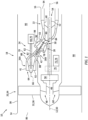
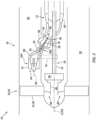
- FIGS. 1-6 are partial schematic illustrations of an aircraft propulsion system with various rotating structure arrangements.
- FIG. 1 illustrates a propulsion system 10 for an aircraft.
- the aircraft may be an airplane, a drone (e.g., an unmanned aerial vehicle (UAV)) or any other manned or unmanned aerial vehicle or system.
- the aircraft propulsion system 10 extends axially along an axial centerline 12 of the aircraft propulsion system 10 between a forward, upstream end 14 of the aircraft propulsion system 10 and an aft, downstream end 16 of the aircraft propulsion system 10.
- This aircraft propulsion system 10 is powered by a gas turbine engine 18.
- the turbine engine 18 of FIG. 1 includes a propulsor section 20, a power turbine (PT) section 22 and a segmented and/or modular turbine engine core 24.
- the engine core 24 includes a core compressor section 26, a core combustor section 28 and a core turbine section 30.
- the core compressor section 26 of FIG. 1 includes a low pressure compressor (LPC) section 26A and a high pressure compressor (HPC) section 26B.
- the core turbine section 30 of FIG. 1 is configured as a high pressure turbine (HPT) section of the turbine engine 18.
- the PT section 22 of FIG. 1 is configured as a low pressure turbine (LPT) section of the turbine engine 18.
- the turbine engine 18, for example, may alternatively be configured as an open rotor engine where the propulsor rotor 32 is configured as an open propulsor rotor; e.g., an un-ducted propulsor rotor.
- the turbine engine 18, for example, may be a turboprop engine, and the propulsor rotor 32 may be a propeller rotor.
- the turbine engine 18 may be a propfan engine, and the propulsor rotor 32 may be a propfan rotor.
- the turbine engine 18 may be a pusher fan engine, and the propulsor rotor 32 may be a pusher fan rotor.
- the propulsor section 20 and the propulsor rotor 32 may be generally described below as the fan section 34 and the fan rotor 36.
- Each bladed engine rotor 32, 36, 40-43 includes at least one rotor base (e.g., a disk or a hub) and at least one array (e.g., stage) of rotor blades arranged circumferentially around and connected to the respective rotor base.
- the rotor blades may be formed integral with or mechanically fastened, welded, brazed and/or otherwise attached to the respective rotor base.
- the PT rotor 40 is connected to a power turbine (PT) shaft 52. At least (or only) the PT rotor 40 and the PT shaft 52 collectively form a power turbine (PT) rotating structure 54.
- the PT rotating structure 54 is rotatable about a power turbine (PT) axis 56, which PT axis 56 may be the same as the propulsor axis 50.
- the PT rotating structure 54 of FIG. 1 is connected to the propulsor rotating structure 48 through a geartrain 58; e.g., an epicyclic gear system, a reduction gear system, a transmission, etc.
- a geartrain 58 e.g., an epicyclic gear system, a reduction gear system, a transmission, etc.
- At least (or only) the propulsor rotor 32, the propulsor shaft 46, the geartrain 58, the PT shaft 52 and the PT rotor 40 collectively form a propulsion rotating assembly 60.
- the PT rotor 40 is mechanically coupled to and operable to drive rotation of the propulsor rotor 32 about the propulsor axis 50.
- the PT rotating structure 54 and its PT rotor 40 may rotate at a different (e.g., faster) rotational velocity than the propulsor rotating structure 48 and its propulsor rotor 32. It is contemplated, however, the PT rotor 40 may alternatively be mechanically coupled to the propulsor rotor 32 through a direct drive drivetrain where the PT rotor 40 and the propulsor rotor 32 may rotate at a common (the same) rotational velocity.
- the LPC rotor 41 is connected to a low pressure compressor (LPC) shaft 62. At least (or only) the LPC rotor 41 and the LPC shaft 62 collectively form a low pressure compressor (LPC) rotating structure 64; e.g., a rotating structure of the engine core 24.
- the LPC rotating structure 64 is rotatable about a low pressure compressor (LPC) axis 66, which LPC axis 66 is offset from the propulsor axis 50 as well as the axial centerline 12.
- LPC axis 66 of FIG. 1 for example, is laterally offset from (e.g., radially outboard of) the propulsor axis 50 and the axial centerline 12.
- This LPC axis 66 of FIG. 1 is further parallel with the propulsor axis 50 and/or the axial centerline 12. However, it is contemplated the LPC axis 66 may also or alternatively be angularly offset from the propulsor axis 50 and/or the axial centerline 12.
- the LPC rotating structure 64 and its members 41 and 62 of FIG. 1 are located radially outboard of the propulsion rotating assembly 60 and its members 40, 46, 52 and 58.
- the propulsion rotating assembly 60 and its PT shaft 52 may extend axially along a side of the LPC rotating structure 64 - not through an internal bore of the LPC rotating structure 64.
- the LPC rotating structure 64 therefore need not be nested with the propulsion rotating assembly 60. This separation of the LPC rotating structure 64 from the propulsion rotating assembly 60 may facilitate, among other things, sizing the LPC shaft 62 smaller than the PT shaft 52, and/or decreasing a size of the LPC section 26A to promote greater turbine engine efficiency.
- the LPC rotating structure 64 of FIG. 1 is mechanically coupled to a power module 68. More particularly, an output from the power module 68 is connected to the LPC shaft 62.
- the power module 68 is thereby operable to (e.g., solely) drive rotation of the LPC rotating structure 64 and its LPC rotor 41 about the LPC axis 66.
- the power module 68 may be a mechanically independent device.
- the power module 68 for example, may be configured to drive rotation of the LPC rotating structure 64 without receiving a torque input from another rotor of the turbine engine 18.
- the power module 68 of FIG. 1 for example, is configured as an electric motor 70, or more generally an electric machine operable as the electric motor 70.
- This electric motor 70 is configured to receive electrical power from an electric power source 72.
- the electric power source 72 may be or otherwise include another as an electric generator 74, or more generally another electric machine operable as the electric generator 74.
- This electric generator 74 may be rotatably driven by the propulsion rotating assembly 60 and, more particularly, the PT rotating structure 54.
- the electric generator 74 for example, may be mechanically coupled to the PT rotating structure 54 through an accessory gearbox 76 for the turbine engine 18.
- the electric power source 72 may also or alternatively be or otherwise include a power storage device (e.g., one or more batteries), and/or another electrical power source onboard the aircraft; e.g., an electric generator with another propulsion system engine, an auxiliary power unit (APU), etc.
- the power module 68 may alternatively be configured as another type of motor such as a fluid motor or the like.
- the HPC rotor 42 is connected to the turbine rotor 43 through a high speed shaft 78. At least (or only) the HPC rotor 42, the high speed shaft 78 and the turbine rotor 43 collectively form a high speed rotating structure 80; e.g., another rotating structure of the engine core 24.
- the high speed rotating structure 80 is rotatable about a high speed axis 82, which high speed axis 82 is offset from one or more of the axes 50, 56, 66 and/or the axial centerline 12.
- the high speed axis 82 of FIG. 1 for example, is angularly offset from each of the axes 50, 56, 66 by a respective included angle (e.g., 84).
- Each included angle may be an acute angle, for example, greater than zero degrees (>0°) and less than (or equal to) forty-five degrees ( ⁇ 45°); e.g., between twenty degrees (20°) and thirty-five degrees (35°).
- the present disclosure is not limited to such an exemplary arrangement.
- the high speed axis 82 (along the high speed rotating structure 80) is further laterally offset from the each of the axes 50, 56, 66.
- the high speed rotating structure 80 and its members 42, 43 and 78 of FIG. 1 are located radially outboard of the propulsion rotating assembly 60 and its member 52.
- the propulsion rotating assembly 60 and its PT shaft 52 may extend axially along a side of the high speed rotating structure 80 - not through an internal bore of the high speed rotating structure 80.
- the high speed rotating structure 80 therefore need not be nested with the propulsion rotating assembly 60.
- the high speed rotating structure 80 and its members 42, 43 and 78 of FIG. 1 are located radially inboard of the LPC rotating structure 64 and its member 62.
- the LPC rotating structure 64 and its LPC shaft 62 may extend axially along a side of the high speed rotating structure 80 - not through the internal bore of the high speed rotating structure 80.
- the high speed rotating structure 80 therefore need not be nested with the LPC rotating structure 64.
- the high speed rotating structure 80 of FIG. 1 is arranged laterally (e.g., radially) between and spaced from (a) the propulsion rotating assembly 60 and its PT shaft 52 and (b) the LPC rotating structure 64 and its LPC shaft 62.
- This separation of the high speed rotating structure 80 from the propulsion rotating assembly 60 and the LPC rotating structure 64 may facilitate, among other things, sizing the high speed shaft 78 smaller than the PT shaft 52 and/or the LPC shaft 62, and/or decreasing a size of the HPC section 26B and/or the core turbine section 30 to promote greater turbine engine efficiency.
- This air is directed through the propulsor section 20 and its duct 38 (longitudinally across the propulsor rotor 32) and into a core flowpath 88 and a bypass flowpath 90 at (e.g., on, adjacent or proximate) an aft, downstream end of the propulsor section 20.
- the core flowpath 88 extends sequentially through the LPC section 26A, the HPC section 26B, the core combustor section 28, the core turbine section 30 and the PT section 22 from an airflow inlet 92 into the core flowpath 88 to a combustion products exhaust 94 from the core flowpath 88.
- the core air is compressed by the LPC rotor 41 and the HPC rotor 42 and directed into the combustion chamber 96 in the core combustor section 28.
- Fuel is injected into the combustion chamber 96 and mixed with the compressed core air to provide a fuel-air mixture.
- This fuel-air mixture is ignited and combustion products thereof flow through and sequentially cause the turbine rotor 43 and the PT rotor 40 to rotate.
- the rotation of the turbine rotor 43 drives rotation of the HPC rotor 42.
- the electric motor 70 of FIG. 1 - the power module 68 - drives rotation of the LPC rotor 41.
- the rotation of the LPC rotor 41 and the HPC rotor 42 thereby compress the core air received from the core inlet 92.
- the accessory gearbox 76 and the electric generator 74 may be arranged axially along the propulsor axis 50 and/or the axial centerline 12 between (a) the PT section 22 and its PT rotor 40 and (b) the propulsor rotor 32 and/or the geartrain 58.
- the accessory gearbox 76 of FIG. 1 is operatively coupled to the PT rotating structure 54 and its PT shaft 52; e.g., to a side of the PT rotating structure 54 via a tower shaft.
- the accessory gearbox 76 and the electric generator 74 may be arranged axially aft of the PT section 22.
- the PT section 22 of FIG. 2 and its PT rotor 40 are arranged axially along the propulsor axis 50 and/or the axial centerline 12 between (a) the accessory gearbox 76 and (b) the propulsor rotor 32 and/or the geartrain 58.
- the accessory gearbox 76 is operably coupled (e.g., inline) to the PT rotating structure 54 and its PT shaft 52.
- the LPC rotating structure 64 may be mechanically independent of a turbine rotor and/or another rotating structure within the turbine engine 18.
- the LPC rotating structure 64 of FIG. 1 is mechanically coupled to and rotatably driven by the power module 68; e.g., the electric motor 70.
- the LPC rotating structure 64 may alternatively be mechanically coupled to another rotating structure within the turbine engine 18.
- the LPC rotating structure 64 of FIG. 3 is mechanically coupled to and rotatably driven by the PT rotating structure 54 and its PT rotor 40, for example, through the accessory gearbox 76 and/or another drivetrain.
- the LPC rotating structure 64 and the high speed rotating structure 80 may each be arranged axially along the propulsor axis 50 and/or the axial centerline 12 between (a) the PT section 22 and its PT rotor 40 and (b) the propulsor rotor 32 and/or the geartrain 58.
- the LPC section 26A of FIG. 1 and its LPC rotor 41 are arranged axially between (a) the high speed rotating structure 80 and (b) the propulsor rotor 32 and/or the geartrain 58.
- the high speed rotating structure 80 of FIG. 1 is arranged axially between (a) the LPC section 26A and its LPC rotor 41 and (b) the PT section 22 and its PT rotor 40.
- the high speed rotating structure 80 of FIG. 1 is also disposed axially along the PT shaft 52 and/or the LPC shaft 62.
- the high speed rotating structure 80 may be arranged axially aft of the PT section 22 and its PT rotor 40.
- the PT section 22 of FIG. 4 and its PT rotor 40 are arranged axially between the LPC rotating structure 64 and the high speed rotating structure 80.
- FIG. 1 is arranged axially between (a) the LPC section 26A and its LPC rotor 41 and (b) the PT section 22 and its PT rotor 40.
- the high speed rotating structure 80 of FIG. 1 is also disposed axially along the PT shaft 52 and/or the LPC shaft 62.
- the high speed rotating structure 80 may be
- both the LPC rotating structure 64 and the high speed rotating structure 80 may be arranged axially aft of the PT section 22 and its PT rotor 40.
- the PT section 22 of FIG. 5 and its PT rotor 40 are arranged axially between (a) the propulsor section 20 and its propulsor rotor 32 and (b) the high speed rotating structure 80.
- the high speed rotating structure 80 of FIG. 5 is arranged axially between (a) the PT section 22 and its PT rotor 40 and (b) the LPC rotating structure 64.
- the present disclosure is not limited to such exemplary arrangements. It is contemplated, for example, two or more of the axes 50, 66 and 82 may alternatively be coaxial while, for example, still providing independent rotating structures / rotating assemblies.
- the rotating structures 48, 54, 64 and 80 are not nested with one another.
- the rotating structures 48, 54, 64 and 80 can be independently configured (e.g., sized, arranged, etc.) to facilitate improved turbine engine efficiently and/or improved rotor-dynamic stability. Referring to FIGS.
- providing independent rotating structures 48, 54, 64 and 80 may also facilitate providing the turbine engine 18 with a modular construction. With such an arrangement, it is contemplated any one or more of the rotating structures 48, 54, 64 and/or 80 may be removed from the turbine engine 18 without, for example, requiring removal and/or disassembly of another one or more of the rotating structures 48, 54, 64 and/or 80.
Landscapes
- Engineering & Computer Science (AREA)
- Chemical & Material Sciences (AREA)
- Combustion & Propulsion (AREA)
- Mechanical Engineering (AREA)
- General Engineering & Computer Science (AREA)
- Aviation & Aerospace Engineering (AREA)
- Turbine Rotor Nozzle Sealing (AREA)
Abstract
A turbine engine (18) includes a propulsor rotor (32) and an engine core (24). The propulsor rotor (32) is rotatable about a propulsor axis (50). The engine core (24) is configured to power operation of the propulsor rotor (32). The engine core (24) includes a core compressor section (26), a core combustor section (28), a core turbine section (30), a first rotating structure (64) and a second rotating structure (80). The first rotating structure (64) includes a first compressor rotor (41) arranged within the core compressor section (26). The first rotating structure (64) is rotatable about a first structure axis (66) which is offset from the propulsor rotor axis (50). The second rotating structure (80) includes a second compressor rotor (42) arranged within the core compressor section (26). The second rotating structure (64) is rotatable about a second structure axis (82) which is offset from the propulsor rotor axis (50) and the first structure axis (66).
Description
- This disclosure relates generally to an aircraft and, more particularly, to a propulsion system for the aircraft.
- Various types and configurations of propulsion systems are known in the art for an aircraft. While these known propulsion systems have various benefits, there is still room in the art for improvement.
- According to an aspect of the present invention, a turbine engine is provided that includes a propulsor rotor, an engine core and a flowpath. The propulsor rotor is rotatable about a propulsor axis. The engine core is configured to power operation of the propulsor rotor. The engine core includes a core compressor section, a core combustor section, a core turbine section, a first rotating structure and a second rotating structure. The first rotating structure includes a first compressor rotor arranged within the core compressor section. The first rotating structure is rotatable about a first structure axis which is offset from the propulsor rotor axis. The second rotating structure includes a second compressor rotor arranged within the core compressor section. The second rotating structure is rotatable about a second structure axis which is offset from the propulsor rotor axis and the first structure axis. The flowpath extends through the core compressor section, the core combustor section and the core turbine section from an inlet into the flowpath to an exhaust from the flowpath.
- According to another aspect of the present invention, another turbine engine is provided that includes a first rotating assembly, a first core rotating structure, a second core rotating structure, a combustor and a flowpath. The first rotating assembly includes a propulsor rotor and a power turbine rotor configured to drive rotation of the propulsor rotor. The first core rotating structure includes a first compressor rotor. The second core rotating structure includes a second compressor rotor and a turbine rotor. The flowpath extends sequentially across the first compressor rotor, the second compressor rotor, the combustor and the turbine rotor. The first rotating assembly does not extend axially through the first core rotating structure or the second core rotating structure. The first core rotating structure does not extend axially through the second core rotating structure.
- According to another aspect of the present invention, another turbine engine is provided that includes a propulsor rotor, a power turbine rotor, a first compressor rotor, an electric machine, a second compressor rotor, a turbine rotor, a combustor and a flowpath. The power turbine rotor is coupled to and is configured to drive rotation of the propulsor rotor. The electric machine is coupled to and is configured to drive rotation of the first compressor rotor. The turbine rotor is coupled to and is configured to drive rotation of the second compressor rotor. The flowpath extends sequentially across the first compressor rotor, the second compressor rotor, the combustor and the turbine rotor.
- In an embodiment of the above, the first rotating assembly may be rotatable about a propulsor axis. The first core rotating structure may be rotatable about a first structure axis. The second core rotating structure may be rotatable about a second structure axis. The propulsor axis may be offset from the first structure axis and/or the second structure axis. In addition or alternatively, the first structure axis may be offset from the second structure axis.
- In another embodiment according to any of the previous embodiments, the turbine engine may also include an electric machine. The first core rotating structure may be configured to be solely rotatably driven by the electric machine.
- In another embodiment according to any of the previous embodiments, the first structure axis may be laterally offset from the propulsor axis.
- In another embodiment according to any of the previous embodiments, the first structure axis may be laterally offset from the second structure axis.
- In another embodiment according to any of the previous embodiments, the second structure axis may be angularly offset from the propulsor axis.
- In another embodiment according to any of the previous embodiments, the second structure axis may be angularly offset from the first structure axis.
- In another embodiment according to any of the previous embodiments, the first structure axis may be parallel with the propulsor axis.
- In another embodiment according to any of the previous embodiments, the first structure axis may be parallel with the second structure axis.
- In another embodiment according to any of the previous embodiments, the first structure axis may be angularly offset from the propulsor axis.
- In another embodiment according to any of the previous embodiments, the turbine engine may also include a power turbine section which includes a power turbine rotor. The power turbine rotor may be mechanically coupled to and configured to drive rotation of the propulsor rotor. The flowpath may extend through the power turbine section from the core turbine section to the exhaust.
- In another embodiment according to any of the previous embodiments, the power turbine rotor may be coaxial with the propulsor rotor.
- In another embodiment according to any of the previous embodiments, the engine core may be located axially between the propulsor rotor and the power turbine rotor along the propulsor axis.
- In another embodiment according to any of the previous embodiments, the first rotating structure may be located axially between the propulsor rotor and the power turbine rotor along the propulsor axis. The power turbine rotor may be located axially between the propulsor rotor and the second rotating structure along the propulsor axis.
- In another embodiment according to any of the previous embodiments, the power turbine rotor may be located axially between the propulsor rotor and the engine core.
- In another embodiment according to any of the previous embodiments, the power turbine rotor may be mechanically coupled to and configured to drive rotation of the first rotating structure.
- In another embodiment according to any of the previous embodiments, the turbine engine may also include an electric machine mechanically coupled to and configured to drive rotation of the first rotating structure.
- In another embodiment according to any of the previous embodiments, the second rotating structure may also include a turbine rotor. The turbine rotor may be arranged within the core turbine section and configured to drive rotation of the second compressor rotor.
- In another embodiment according to any of the previous embodiments, the propulsor rotor may be configured as or otherwise include a fan rotor.
- The present disclosure may include any one or more of the individual features disclosed above and/or below alone or in any combination thereof.
- The foregoing features and the operation of the invention will become more apparent in light of the following description and the accompanying drawings.
-
FIGS. 1-6 are partial schematic illustrations of an aircraft propulsion system with various rotating structure arrangements. -
FIG. 1 illustrates apropulsion system 10 for an aircraft. The aircraft may be an airplane, a drone (e.g., an unmanned aerial vehicle (UAV)) or any other manned or unmanned aerial vehicle or system. Theaircraft propulsion system 10 extends axially along an axial centerline 12 of theaircraft propulsion system 10 between a forward,upstream end 14 of theaircraft propulsion system 10 and an aft,downstream end 16 of theaircraft propulsion system 10. Thisaircraft propulsion system 10 is powered by agas turbine engine 18. - The
turbine engine 18 ofFIG. 1 includes a propulsor section 20, a power turbine (PT)section 22 and a segmented and/or modularturbine engine core 24. Theengine core 24 includes acore compressor section 26, acore combustor section 28 and acore turbine section 30. Thecore compressor section 26 ofFIG. 1 includes a low pressure compressor (LPC)section 26A and a high pressure compressor (HPC)section 26B. Thecore turbine section 30 ofFIG. 1 is configured as a high pressure turbine (HPT) section of theturbine engine 18. ThePT section 22 ofFIG. 1 is configured as a low pressure turbine (LPT) section of theturbine engine 18. - The propulsor section 20 includes a bladed propulsor rotor 32. The propulsor section 20 of
FIG. 1 , in particular, is configured as a fan section 34 of theturbine engine 18, and the propulsor rotor 32 is configured as a fan rotor 36 housed within afan duct 38 of theturbine engine 18. Theturbine engine 18, for example, may be a turbofan engine; e.g., a high-bypass turbofan engine. The present disclosure, however, is not limited to such an exemplary engine arrangement nor to a gas turbine engine with a ducted propulsor rotor. Theturbine engine 18, for example, may alternatively be configured as an open rotor engine where the propulsor rotor 32 is configured as an open propulsor rotor; e.g., an un-ducted propulsor rotor. Theturbine engine 18, for example, may be a turboprop engine, and the propulsor rotor 32 may be a propeller rotor. In another example, theturbine engine 18 may be a propfan engine, and the propulsor rotor 32 may be a propfan rotor. In still another example, theturbine engine 18 may be a pusher fan engine, and the propulsor rotor 32 may be a pusher fan rotor. However, for ease of description, the propulsor section 20 and the propulsor rotor 32 may be generally described below as the fan section 34 and the fan rotor 36. - The
PT section 22 includes a bladed power turbine (PT)rotor 40. TheLPC section 26A includes a bladed low pressure compressor (LPC)rotor 41. TheHPC section 26B includes a bladed high pressure compressor (HPC)rotor 42. Thecore turbine section 30 includes a bladedcore turbine rotor 43. Theturbine rotor 43 ofFIG. 1 is configured as a high pressure turbine (HPT) rotor of theturbine engine 18. ThePT rotor 40 ofFIG. 1 is configured as a low pressure turbine (LPT) rotor of theturbine engine 18. - Each bladed engine rotor 32, 36, 40-43 includes at least one rotor base (e.g., a disk or a hub) and at least one array (e.g., stage) of rotor blades arranged circumferentially around and connected to the respective rotor base. The rotor blades, for example, may be formed integral with or mechanically fastened, welded, brazed and/or otherwise attached to the respective rotor base.
- The propulsor rotor 32 is connected to a
propulsor shaft 46. At least (or only) the propulsor rotor 32 and thepropulsor shaft 46 collectively form apropulsor rotating structure 48. Thepropulsor rotating structure 48 is rotatable about a propulsor axis 50, which propulsor axis 50 may be the same as (e.g., coaxial with) or different than the axial centerline 12. - The
PT rotor 40 is connected to a power turbine (PT)shaft 52. At least (or only) thePT rotor 40 and thePT shaft 52 collectively form a power turbine (PT) rotatingstructure 54. ThePT rotating structure 54 is rotatable about a power turbine (PT)axis 56, whichPT axis 56 may be the same as the propulsor axis 50. - The
PT rotating structure 54 ofFIG. 1 is connected to thepropulsor rotating structure 48 through ageartrain 58; e.g., an epicyclic gear system, a reduction gear system, a transmission, etc. At least (or only) the propulsor rotor 32, thepropulsor shaft 46, thegeartrain 58, thePT shaft 52 and thePT rotor 40 collectively form apropulsion rotating assembly 60. With this arrangement, thePT rotor 40 is mechanically coupled to and operable to drive rotation of the propulsor rotor 32 about the propulsor axis 50. Moreover, thePT rotating structure 54 and itsPT rotor 40 may rotate at a different (e.g., faster) rotational velocity than thepropulsor rotating structure 48 and its propulsor rotor 32. It is contemplated, however, thePT rotor 40 may alternatively be mechanically coupled to the propulsor rotor 32 through a direct drive drivetrain where thePT rotor 40 and the propulsor rotor 32 may rotate at a common (the same) rotational velocity. - The
LPC rotor 41 is connected to a low pressure compressor (LPC)shaft 62. At least (or only) theLPC rotor 41 and theLPC shaft 62 collectively form a low pressure compressor (LPC) rotatingstructure 64; e.g., a rotating structure of theengine core 24. The LPCrotating structure 64 is rotatable about a low pressure compressor (LPC)axis 66, whichLPC axis 66 is offset from the propulsor axis 50 as well as the axial centerline 12. TheLPC axis 66 ofFIG. 1 , for example, is laterally offset from (e.g., radially outboard of) the propulsor axis 50 and the axial centerline 12. ThisLPC axis 66 ofFIG. 1 is further parallel with the propulsor axis 50 and/or the axial centerline 12. However, it is contemplated theLPC axis 66 may also or alternatively be angularly offset from the propulsor axis 50 and/or the axial centerline 12. - The LPC
rotating structure 64 and itsmembers FIG. 1 are located radially outboard of thepropulsion rotating assembly 60 and itsmembers LPC rotating structure 64 to a lateral side (e.g., a radial outer side) of thepropulsion rotating assembly 60, thepropulsion rotating assembly 60 and itsPT shaft 52 may extend axially along a side of the LPC rotating structure 64 - not through an internal bore of theLPC rotating structure 64. The LPCrotating structure 64 therefore need not be nested with thepropulsion rotating assembly 60. This separation of theLPC rotating structure 64 from thepropulsion rotating assembly 60 may facilitate, among other things, sizing theLPC shaft 62 smaller than thePT shaft 52, and/or decreasing a size of theLPC section 26A to promote greater turbine engine efficiency. - The LPC
rotating structure 64 ofFIG. 1 is mechanically coupled to a power module 68. More particularly, an output from the power module 68 is connected to theLPC shaft 62. The power module 68 is thereby operable to (e.g., solely) drive rotation of theLPC rotating structure 64 and itsLPC rotor 41 about theLPC axis 66. The power module 68 may be a mechanically independent device. The power module 68, for example, may be configured to drive rotation of theLPC rotating structure 64 without receiving a torque input from another rotor of theturbine engine 18. The power module 68 ofFIG. 1 , for example, is configured as an electric motor 70, or more generally an electric machine operable as the electric motor 70. This electric motor 70 is configured to receive electrical power from an electric power source 72. The electric power source 72 may be or otherwise include another as an electric generator 74, or more generally another electric machine operable as the electric generator 74. This electric generator 74 may be rotatably driven by thepropulsion rotating assembly 60 and, more particularly, thePT rotating structure 54. The electric generator 74, for example, may be mechanically coupled to thePT rotating structure 54 through anaccessory gearbox 76 for theturbine engine 18. The electric power source 72 may also or alternatively be or otherwise include a power storage device (e.g., one or more batteries), and/or another electrical power source onboard the aircraft; e.g., an electric generator with another propulsion system engine, an auxiliary power unit (APU), etc. However, it is contemplated the power module 68 may alternatively be configured as another type of motor such as a fluid motor or the like. - The
HPC rotor 42 is connected to theturbine rotor 43 through ahigh speed shaft 78. At least (or only) theHPC rotor 42, thehigh speed shaft 78 and theturbine rotor 43 collectively form a highspeed rotating structure 80; e.g., another rotating structure of theengine core 24. The highspeed rotating structure 80 is rotatable about ahigh speed axis 82, whichhigh speed axis 82 is offset from one or more of theaxes high speed axis 82 ofFIG. 1 , for example, is angularly offset from each of theaxes axes - The high
speed rotating structure 80 and itsmembers FIG. 1 are located radially outboard of thepropulsion rotating assembly 60 and itsmember 52. By locating an entirety of the highspeed rotating structure 80 to the lateral side (e.g., the radial outer side) of thepropulsion rotating assembly 60, thepropulsion rotating assembly 60 and itsPT shaft 52 may extend axially along a side of the high speed rotating structure 80 - not through an internal bore of the highspeed rotating structure 80. The highspeed rotating structure 80 therefore need not be nested with thepropulsion rotating assembly 60. Similarly, the highspeed rotating structure 80 and itsmembers FIG. 1 are located radially inboard of theLPC rotating structure 64 and itsmember 62. By locating the entirety of the highspeed rotating structure 80 to a lateral side (e.g., a radial outer side) of theLPC rotating structure 64, theLPC rotating structure 64 and itsLPC shaft 62 may extend axially along a side of the high speed rotating structure 80 - not through the internal bore of the highspeed rotating structure 80. The highspeed rotating structure 80 therefore need not be nested with theLPC rotating structure 64. More particularly, the highspeed rotating structure 80 ofFIG. 1 is arranged laterally (e.g., radially) between and spaced from (a) thepropulsion rotating assembly 60 and itsPT shaft 52 and (b) theLPC rotating structure 64 and itsLPC shaft 62. This separation of the highspeed rotating structure 80 from thepropulsion rotating assembly 60 and theLPC rotating structure 64 may facilitate, among other things, sizing thehigh speed shaft 78 smaller than thePT shaft 52 and/or theLPC shaft 62, and/or decreasing a size of theHPC section 26B and/or thecore turbine section 30 to promote greater turbine engine efficiency. - During operation, air enters the
aircraft propulsion system 10 and itsturbine engine 18 through anairflow inlet 86. This air is directed through the propulsor section 20 and its duct 38 (longitudinally across the propulsor rotor 32) and into acore flowpath 88 and abypass flowpath 90 at (e.g., on, adjacent or proximate) an aft, downstream end of the propulsor section 20. Thecore flowpath 88 extends sequentially through theLPC section 26A, theHPC section 26B, thecore combustor section 28, thecore turbine section 30 and thePT section 22 from anairflow inlet 92 into thecore flowpath 88 to a combustion products exhaust 94 from thecore flowpath 88. More particularly, thecore flowpath 88 extends sequentially from thecore inlet 92, longitudinally across theLPC rotor 41, theHPC rotor 42, a combustion chamber 96 (e.g., an annular combustion chamber) within a combustor 98 (e.g., an annular combustor) of thecore combustor section 28, theturbine rotor 43 and thePT rotor 40, to thecore exhaust 94. The air entering thiscore flowpath 88 may be referred to as "core air". Thebypass flowpath 90 extends through a bypass duct (e.g., an annular duct) from an airflow inlet into thebypass flowpath 90 to an airflow exhaust from thebypass flowpath 90. This bypass flowpath 90 bypasses theengine core 24 and each of itsengine sections PT section 22. The air entering thisbypass flowpath 90 may be referred to as "bypass air". - The core air is compressed by the
LPC rotor 41 and theHPC rotor 42 and directed into thecombustion chamber 96 in thecore combustor section 28. Fuel is injected into thecombustion chamber 96 and mixed with the compressed core air to provide a fuel-air mixture. This fuel-air mixture is ignited and combustion products thereof flow through and sequentially cause theturbine rotor 43 and thePT rotor 40 to rotate. The rotation of theturbine rotor 43 drives rotation of theHPC rotor 42. The electric motor 70 ofFIG. 1 - the power module 68 - drives rotation of theLPC rotor 41. The rotation of theLPC rotor 41 and theHPC rotor 42 thereby compress the core air received from thecore inlet 92. The rotation of thePT rotor 40 drives rotation of the propulsor rotor 32, and thePT rotor 40 ofFIG. 1 also mechanically powers operation of the electric generator 74 to provide electric power to the electric motor 70, for example. The rotation of the propulsor rotor 32 propels the bypass air through thebypass flowpath 90 and out of theaircraft propulsion system 10 through the bypass exhaust to provide aircraft thrust. The propulsion of the bypass air may account for a majority of thrust generated by theaircraft propulsion system 10 and itsturbine engine 18, e.g., more than seventy-five percent (75%) of engine thrust. Theaircraft propulsion system 10 of the present disclosure, however, is not limited to the foregoing exemplary thrust ratio. - In some embodiments, referring to
FIG. 1 , theaccessory gearbox 76 and the electric generator 74 may be arranged axially along the propulsor axis 50 and/or the axial centerline 12 between (a) thePT section 22 and itsPT rotor 40 and (b) the propulsor rotor 32 and/or thegeartrain 58. Theaccessory gearbox 76 ofFIG. 1 , for example, is operatively coupled to thePT rotating structure 54 and itsPT shaft 52; e.g., to a side of thePT rotating structure 54 via a tower shaft. In other embodiments, referring toFIG. 2 , theaccessory gearbox 76 and the electric generator 74 may be arranged axially aft of thePT section 22. ThePT section 22 ofFIG. 2 and itsPT rotor 40, for example, are arranged axially along the propulsor axis 50 and/or the axial centerline 12 between (a) theaccessory gearbox 76 and (b) the propulsor rotor 32 and/or thegeartrain 58. Here, theaccessory gearbox 76 is operably coupled (e.g., inline) to thePT rotating structure 54 and itsPT shaft 52. - In some embodiments, referring to
FIG. 1 , theLPC rotating structure 64 may be mechanically independent of a turbine rotor and/or another rotating structure within theturbine engine 18. The LPCrotating structure 64 ofFIG. 1 , for example, is mechanically coupled to and rotatably driven by the power module 68; e.g., the electric motor 70. In other embodiments, referring toFIG. 3 , theLPC rotating structure 64 may alternatively be mechanically coupled to another rotating structure within theturbine engine 18. The LPCrotating structure 64 ofFIG. 3 , for example, is mechanically coupled to and rotatably driven by thePT rotating structure 54 and itsPT rotor 40, for example, through theaccessory gearbox 76 and/or another drivetrain. - In some embodiments, referring to
FIG. 1 , theLPC rotating structure 64 and the highspeed rotating structure 80 may each be arranged axially along the propulsor axis 50 and/or the axial centerline 12 between (a) thePT section 22 and itsPT rotor 40 and (b) the propulsor rotor 32 and/or thegeartrain 58. TheLPC section 26A ofFIG. 1 and itsLPC rotor 41, for example, are arranged axially between (a) the highspeed rotating structure 80 and (b) the propulsor rotor 32 and/or thegeartrain 58. The highspeed rotating structure 80 ofFIG. 1 is arranged axially between (a) theLPC section 26A and itsLPC rotor 41 and (b) thePT section 22 and itsPT rotor 40. The highspeed rotating structure 80 ofFIG. 1 is also disposed axially along thePT shaft 52 and/or theLPC shaft 62. In other embodiments, referring toFIG. 4 , the highspeed rotating structure 80 may be arranged axially aft of thePT section 22 and itsPT rotor 40. ThePT section 22 ofFIG. 4 and itsPT rotor 40, for example, are arranged axially between theLPC rotating structure 64 and the highspeed rotating structure 80. In still other embodiments, referring toFIG. 5 , both theLPC rotating structure 64 and the highspeed rotating structure 80 may be arranged axially aft of thePT section 22 and itsPT rotor 40. ThePT section 22 ofFIG. 5 and itsPT rotor 40, for example, are arranged axially between (a) the propulsor section 20 and its propulsor rotor 32 and (b) the highspeed rotating structure 80. The highspeed rotating structure 80 ofFIG. 5 is arranged axially between (a) thePT section 22 and itsPT rotor 40 and (b) theLPC rotating structure 64. - While the
axes FIGS. 1-5 are laterally and/or angularly offset from one another, the present disclosure is not limited to such exemplary arrangements. It is contemplated, for example, two or more of theaxes axes FIG. 6 are coaxial, the rotatingstructures structures FIGS. 1-6 , providing independentrotating structures turbine engine 18 with a modular construction. With such an arrangement, it is contemplated any one or more of therotating structures turbine engine 18 without, for example, requiring removal and/or disassembly of another one or more of therotating structures - While various embodiments of the present disclosure have been described, it will be apparent to those of ordinary skill in the art that many more embodiments and implementations are possible within the scope of the disclosure. For example, the present disclosure as described herein includes several aspects and embodiments that include particular features. Although these features may be described individually, it is within the scope of the present disclosure that some or all of these features may be combined with any one of the aspects and remain within the scope of the disclosure. Accordingly, the present disclosure is not to be restricted except in light of the attached claims and their equivalents.
Claims (15)
- A turbine engine (18), comprising:a propulsor rotor (32) rotatable about a propulsor axis (50);an engine core (24) configured to power operation of the propulsor rotor (32), the engine core (24) including a core compressor section (26), a core combustor section (28), a core turbine section (30), a first rotating structure (64) and a second rotating structure (80);the first rotating structure (54) comprising a first compressor rotor (41) arranged within the core compressor section (26), and the first rotating structure (64) rotatable about a first structure axis (66) which is offset from the propulsor axis (50); andthe second rotating structure (80) comprising a second compressor rotor (42) arranged within the core compressor section (26), and the second rotating structure (80) rotatable about a second structure axis (82) which is offset from the propulsor axis (50) and the first structure axis (66); anda flowpath (88) extending through the core compressor section (26), the core combustor section (28) and the core turbine section (30) from an inlet (86) into the flowpath (88) to an exhaust (94) from the flowpath (88).
- The turbine engine (18) of claim 1, wherein the first structure axis (66) is laterally offset from the propulsor axis (50).
- The turbine engine (18) of claim 1 or 2, wherein the first structure axis (66) is laterally offset from the second structure axis (82).
- The turbine engine (18) of claim 1, 2 or 3, wherein the second structure axis (82) is angularly offset from the propulsor axis (50).
- The turbine engine (18) of any preceding claim, wherein the second structure axis (82) is angularly offset from the first structure axis (66), or wherein the first structure axis (66) is parallel with the second structure axis (82).
- The turbine engine (18) of any preceding claim, wherein the first structure axis (66) is parallel with the propulsor axis (50).
- The turbine engine (18) of any preceding claim, further comprising:a power turbine section (22) comprising a power turbine rotor (40), the power turbine rotor (40) mechanically coupled to and configured to drive rotation of the propulsor rotor (32); andthe flowpath (88) extending through the power turbine section (22) from the core turbine section (30) to the exhaust (94).
- The turbine engine (18) of claim 7, wherein the power turbine rotor (40) is coaxial with the propulsor rotor (32).
- The turbine engine (18) of claim 7 or 8, wherein the engine core (24) is located axially between the propulsor rotor (32) and the power turbine rotor (40) along the propulsor axis (50).
- The turbine engine (18) of claim 7 or 8, whereinthe first rotating structure (64) is located axially between the propulsor rotor (32) and the power turbine rotor (40) along the propulsor axis (50); andthe power turbine rotor (40) is located axially between the propulsor rotor (32) and the second rotating structure (80) along the propulsor axis (50).
- The turbine engine (18) of claim 7 or 8, wherein the power turbine rotor (40) is located axially between the propulsor rotor (32) and the engine core (24).
- The turbine engine (18) of any of claims 7 to 11, wherein the power turbine rotor (40) is mechanically coupled to and configured to drive rotation of the first rotating structure (64).
- The turbine engine (18) of any preceding claim, further comprising an electric machine (74) mechanically coupled to and configured to drive rotation of the first rotating structure (64).
- The turbine engine (18) of any preceding claim, whereinthe second rotating structure (80) further comprises a turbine rotor (43); andthe turbine rotor (43) is arranged within the core turbine section (30) and configured to drive rotation of the second compressor rotor (42).
- The turbine engine (18) of any preceding claim, wherein the propulsor rotor (32) comprises a fan rotor (36).
Applications Claiming Priority (1)
| Application Number | Priority Date | Filing Date | Title |
|---|---|---|---|
| US18/217,830 US12428986B2 (en) | 2023-07-03 | 2023-07-03 | Aircraft propulsion system engine with multiple independent rotating structures |
Publications (1)
| Publication Number | Publication Date |
|---|---|
| EP4488496A1 true EP4488496A1 (en) | 2025-01-08 |
Family
ID=90971376
Family Applications (1)
| Application Number | Title | Priority Date | Filing Date |
|---|---|---|---|
| EP24173929.1A Pending EP4488496A1 (en) | 2023-07-03 | 2024-05-02 | Aircraft propulsion system engine with multiple independent rotating structures |
Country Status (2)
| Country | Link |
|---|---|
| US (1) | US12428986B2 (en) |
| EP (1) | EP4488496A1 (en) |
Citations (5)
| Publication number | Priority date | Publication date | Assignee | Title |
|---|---|---|---|---|
| US2073191A (en) * | 1935-02-13 | 1937-03-09 | Belluzzo Giuseppe | Combustion turbine |
| DE4113247A1 (en) * | 1991-04-23 | 1992-10-29 | Bayerische Motoren Werke Ag | Gas turbine plant for motor vehicle - has compressor rotor and turbine rotor formed by rotors of mass-produced exhaust gas turbochargers |
| US20200141416A1 (en) * | 2016-12-20 | 2020-05-07 | Pratt & Whitney Canada Corp. | Reverse flow engine architecture |
| US20210172333A1 (en) * | 2019-12-06 | 2021-06-10 | United Technologies Corporation | Systems and methods for hybrid electric turbine engines |
| US11136899B2 (en) * | 2019-06-14 | 2021-10-05 | Raytheon Technologies Corporation | Integrated electro-aero-thermal turbine engine |
Family Cites Families (11)
| Publication number | Priority date | Publication date | Assignee | Title |
|---|---|---|---|---|
| WO2014092778A1 (en) * | 2012-12-10 | 2014-06-19 | United Technologies Corporation | Dual filtration particle separator |
| DE102013213518A1 (en) | 2013-07-10 | 2015-01-15 | Rolls-Royce Deutschland Ltd & Co Kg | Turbofan engine |
| US10024235B2 (en) | 2014-03-03 | 2018-07-17 | United Technologies Corporation | Offset core engine architecture |
| US10415466B2 (en) | 2014-10-27 | 2019-09-17 | United Technologies Corporation | Offset cores for gas turbine engines |
| US10822101B2 (en) * | 2017-07-21 | 2020-11-03 | General Electric Company | Vertical takeoff and landing aircraft having a forward thrust propulsor |
| US11168616B2 (en) * | 2018-05-16 | 2021-11-09 | Raytheon Technologies Corporation | Hybrid electric fan with improved low pressure compressor |
| US11168612B2 (en) * | 2018-09-21 | 2021-11-09 | Pratt & Whitney Canada Corp. | Signal processing for variable geometry mechanism control |
| US11319882B2 (en) * | 2019-09-10 | 2022-05-03 | Raytheon Technologies Corporation | Gear and electric amplification of generator motor compressor and turbine drives |
| US11624319B2 (en) * | 2020-05-15 | 2023-04-11 | Pratt & Whitney Canada Corp. | Reverse-flow gas turbine engine with electric motor |
| US20220074349A1 (en) * | 2020-09-08 | 2022-03-10 | Pratt & Whitney Canada Corp. | Split compressor gas turbine engine |
| US11608797B2 (en) * | 2021-06-23 | 2023-03-21 | Raytheon Technologies Corporation | Hybrid electric engine including auxiliary compressor |
-
2023
- 2023-07-03 US US18/217,830 patent/US12428986B2/en active Active
-
2024
- 2024-05-02 EP EP24173929.1A patent/EP4488496A1/en active Pending
Patent Citations (5)
| Publication number | Priority date | Publication date | Assignee | Title |
|---|---|---|---|---|
| US2073191A (en) * | 1935-02-13 | 1937-03-09 | Belluzzo Giuseppe | Combustion turbine |
| DE4113247A1 (en) * | 1991-04-23 | 1992-10-29 | Bayerische Motoren Werke Ag | Gas turbine plant for motor vehicle - has compressor rotor and turbine rotor formed by rotors of mass-produced exhaust gas turbochargers |
| US20200141416A1 (en) * | 2016-12-20 | 2020-05-07 | Pratt & Whitney Canada Corp. | Reverse flow engine architecture |
| US11136899B2 (en) * | 2019-06-14 | 2021-10-05 | Raytheon Technologies Corporation | Integrated electro-aero-thermal turbine engine |
| US20210172333A1 (en) * | 2019-12-06 | 2021-06-10 | United Technologies Corporation | Systems and methods for hybrid electric turbine engines |
Also Published As
| Publication number | Publication date |
|---|---|
| US12428986B2 (en) | 2025-09-30 |
| US20250012213A1 (en) | 2025-01-09 |
Similar Documents
| Publication | Publication Date | Title |
|---|---|---|
| EP3832089B1 (en) | Systems and methods for hybrid electric turbine engines | |
| EP1825117B1 (en) | Turbine engine with differential gear driven fan and compressor | |
| EP4389607A1 (en) | Hybrid aircraft propulsion system with remotely located electric machine | |
| EP4653321A2 (en) | Open rotor aircraft propulsion system with bypass flowpath | |
| EP4509703A1 (en) | Aircraft powerplant with electric powertrain | |
| EP4607007A1 (en) | Exhaust duct mounting structure for hybrid aircraft powerplant | |
| EP4389605A2 (en) | Electric aircraft propulsion unit(s) with multiple propulsor rotors | |
| US12428986B2 (en) | Aircraft propulsion system engine with multiple independent rotating structures | |
| EP4325087A1 (en) | Aircraft propulsion system geartrain | |
| US12146443B2 (en) | Boosting gas turbine engine power with fluid motor | |
| US12454911B2 (en) | Bleeding core air from a turbine engine core flowpath | |
| US12540550B2 (en) | Tie shaft for engine rotating assembly | |
| US12397924B2 (en) | Open rotor aircraft propulsion system with bypass flowpath | |
| US20250027447A1 (en) | Turbine engine vane array structure with air particle separator | |
| US12410712B1 (en) | Rotor blade with apertured cooling air deflector | |
| EP4310302A1 (en) | Aircraft system with gas turbine engine powered compressor | |
| US12404811B1 (en) | Aircraft powerplant gearbox with selectable power coupler | |
| US12467365B1 (en) | In situ balancing mass(es) for aircraft powerplant | |
| US12523161B1 (en) | Aircraft powerplant gearbox with selectable power coupler | |
| EP4282764A1 (en) | Aircraft propulsion system with adjustable thrust propulsor | |
| US20250093030A1 (en) | Multi-piece injector nozzle for a turbine engine | |
| EP4553309A1 (en) | Turbine engine accessory system with multiple gearboxes | |
| EP4530458A1 (en) | Selective power distribution for an aircraft propulsion system | |
| EP4589124A1 (en) | Bolted connection between mounting bracket and aircraft engine case(s) |
Legal Events
| Date | Code | Title | Description |
|---|---|---|---|
| PUAI | Public reference made under article 153(3) epc to a published international application that has entered the european phase |
Free format text: ORIGINAL CODE: 0009012 |
|
| STAA | Information on the status of an ep patent application or granted ep patent |
Free format text: STATUS: THE APPLICATION HAS BEEN PUBLISHED |
|
| AK | Designated contracting states |
Kind code of ref document: A1 Designated state(s): AL AT BE BG CH CY CZ DE DK EE ES FI FR GB GR HR HU IE IS IT LI LT LU LV MC ME MK MT NL NO PL PT RO RS SE SI SK SM TR |
|
| STAA | Information on the status of an ep patent application or granted ep patent |
Free format text: STATUS: REQUEST FOR EXAMINATION WAS MADE |
|
| 17P | Request for examination filed |
Effective date: 20250708 |