EP4488438A1 - Washing machine driving system - Google Patents
Washing machine driving system Download PDFInfo
- Publication number
- EP4488438A1 EP4488438A1 EP23921579.1A EP23921579A EP4488438A1 EP 4488438 A1 EP4488438 A1 EP 4488438A1 EP 23921579 A EP23921579 A EP 23921579A EP 4488438 A1 EP4488438 A1 EP 4488438A1
- Authority
- EP
- European Patent Office
- Prior art keywords
- clutch
- coil
- coupled
- rotor
- stator
- Prior art date
- Legal status (The legal status is an assumption and is not a legal conclusion. Google has not performed a legal analysis and makes no representation as to the accuracy of the status listed.)
- Granted
Links
Images




Classifications
-
- D—TEXTILES; PAPER
- D06—TREATMENT OF TEXTILES OR THE LIKE; LAUNDERING; FLEXIBLE MATERIALS NOT OTHERWISE PROVIDED FOR
- D06F—LAUNDERING, DRYING, IRONING, PRESSING OR FOLDING TEXTILE ARTICLES
- D06F37/00—Details specific to washing machines covered by groups D06F21/00 - D06F25/00
- D06F37/30—Driving arrangements
-
- D—TEXTILES; PAPER
- D06—TREATMENT OF TEXTILES OR THE LIKE; LAUNDERING; FLEXIBLE MATERIALS NOT OTHERWISE PROVIDED FOR
- D06F—LAUNDERING, DRYING, IRONING, PRESSING OR FOLDING TEXTILE ARTICLES
- D06F37/00—Details specific to washing machines covered by groups D06F21/00 - D06F25/00
- D06F37/30—Driving arrangements
- D06F37/304—Arrangements or adaptations of electric motors
-
- D—TEXTILES; PAPER
- D06—TREATMENT OF TEXTILES OR THE LIKE; LAUNDERING; FLEXIBLE MATERIALS NOT OTHERWISE PROVIDED FOR
- D06F—LAUNDERING, DRYING, IRONING, PRESSING OR FOLDING TEXTILE ARTICLES
- D06F37/00—Details specific to washing machines covered by groups D06F21/00 - D06F25/00
- D06F37/30—Driving arrangements
- D06F37/40—Driving arrangements for driving the receptacle and an agitator or impeller, e.g. alternatively
-
- H—ELECTRICITY
- H02—GENERATION; CONVERSION OR DISTRIBUTION OF ELECTRIC POWER
- H02K—DYNAMO-ELECTRIC MACHINES
- H02K7/00—Arrangements for handling mechanical energy structurally associated with dynamo-electric machines, e.g. structural association with mechanical driving motors or auxiliary dynamo-electric machines
- H02K7/10—Structural association with clutches, brakes, gears, pulleys or mechanical starters
- H02K7/108—Structural association with clutches, brakes, gears, pulleys or mechanical starters with friction clutches
-
- H—ELECTRICITY
- H02—GENERATION; CONVERSION OR DISTRIBUTION OF ELECTRIC POWER
- H02K—DYNAMO-ELECTRIC MACHINES
- H02K7/00—Arrangements for handling mechanical energy structurally associated with dynamo-electric machines, e.g. structural association with mechanical driving motors or auxiliary dynamo-electric machines
- H02K7/10—Structural association with clutches, brakes, gears, pulleys or mechanical starters
- H02K7/11—Structural association with clutches, brakes, gears, pulleys or mechanical starters with dynamo-electric clutches
-
- H—ELECTRICITY
- H02—GENERATION; CONVERSION OR DISTRIBUTION OF ELECTRIC POWER
- H02K—DYNAMO-ELECTRIC MACHINES
- H02K7/00—Arrangements for handling mechanical energy structurally associated with dynamo-electric machines, e.g. structural association with mechanical driving motors or auxiliary dynamo-electric machines
- H02K7/10—Structural association with clutches, brakes, gears, pulleys or mechanical starters
- H02K7/116—Structural association with clutches, brakes, gears, pulleys or mechanical starters with gears
Definitions
- the present disclosure relates to a washing machine drive system, and more specifically, to a washing machine drive system having a clutch.
- a washing machine is driven in two main operating modes (washing mode, dehydration mode) with different operating conditions.
- the washing machine is provided with a planetary gear set and a clutch, and operates an output shaft with a low speed and high torque with a gear ratio of n:1 (washing mode), or operates the output shaft with a high speed and low torque with a gear ratio of 1: 1 (dehydration mode).
- the output shaft refers to a shaft coupled to a drum to rotate the drum.
- the drum may be referred to as an "inner tub”.
- the output shaft should be operated at low speed and high torque.
- the output shaft should be operated at high speed and low torque.
- the washing machine drive system has components for changing a rotational force of a rotor shaft transmitted to the output shaft between the initial dehydration mode and the dehydration mode, such as a planetary gear set and a clutch.
- Korean Patent No. KR10-1920812 discloses a structure in which the position of a reduction coupling unit including a planetary gear set is moved forward and backward using a lever while changing the gear ratio.
- the reduction coupling unit moves forward according to the operation of a lever of a lever unit, and accordingly, the teeth formed on a coupling cap of the reduction coupling unit engage with the teeth formed on the drum, so that the washing machine operates at low speed and high torque.
- the reduction coupling unit moves backward according to the operation of the lever of the lever unit, and accordingly, the teeth formed on the coupling housing of the reduction coupling unit engage with the teeth formed on the rotor housing, so that the washing machine operates at high speed and low torque.
- the sun gear equipped in the planetary gear set is mounted on the bearing on the output shaft, and the output shaft is supported by only one bearing.
- the planetary gear set acts as a support point, and the output shaft is supported by the planetary gear set and the bearing, but in the dehydration mode, the rotor, the planetary gear set, and the output shaft operate as one, and the output shaft is supported by only one bearing, so there is a problem of low durability in the dehydration mode in which the operation is performed at high speed and low torque.
- An object of the present disclosure seeks to solve is to provide a washing machine drive system that can apply a reduction ratio while maintaining the rotation of a rotor by implementing a neutral mode of a clutch.
- an object of the present disclosure is to provide a washing machine drive system that can generate high torque by applying a reduction ratio without stopping the rotation of the rotor.
- an object of the present disclosure is to provide a washing machine drive system that can apply a helical gear to the detailed configuration of a planetary gear set.
- an object of the present disclosure is to provide a washing machine drive system that can improve space efficiency while making the rotational speed of a sun gear and the rotational speed of a carrier different.
- an object of the present disclosure is to provide a washing machine drive system that can improve space efficiency while making the rotational speed of a carrier and the rotational speed of a ring gear different.
- an object of the present disclosure is to provide a washing machine drive system that can stop the rotation of a ring gear that is spline-coupled with the clutch actuator by coupling a clutch actuator to a clutch stator.
- an object of the present disclosure is to provide a washing machine drive system that can rotate the ring gear that is spline-coupled with the clutch actuator together with the rotor by coupling the clutch actuator to the rotor.
- an object of the present disclosure is to provide a washing machine drive system that can reduce power consumption by maintaining the position of the clutch actuator even when the clutch actuator is moved in a vertical direction and the supply of current is stopped.
- an object of the present disclosure is to provide a washing machine drive system that can improve space efficiency and reduce size.
- an object of the present disclosure is to provide a washing machine drive system that can maintain the position of the clutch actuator even when the supply of current to first to third coils is stopped by forming three stable points.
- a washing machine drive system including: a housing; a motor stator coupled to the housing; a rotor facing the motor stator; an output shaft bearing-coupled to the housing; a planetary gear set coupled to the rotor and spline-coupled to an outer peripheral surface of the output shaft; a clutch stator coupled to the motor stator; and a clutch actuator spline-coupled to an outer peripheral surface of the planetary gear set so as to be vertically movable and facing the clutch stator.
- the clutch stator includes first to third coils arranged in parallel in a vertical direction, the clutch actuator is fixed to the rotor and transmits rotational force of the rotor to the output shaft at a 1:1 ratio when current is supplied to the first coil, the clutch actuator is fixed to the clutch stator, reduces the rotational force of the rotor at a gear ratio of n: 1, and transmits the reduced rotational force to the output shaft when current is supplied to the third coil, and the clutch actuator is disengaged from the rotor or the clutch stator when current is supplied to the second coil.
- a neutral mode of the clutch is implemented, and thus, a reduction ratio can be applied while maintaining the rotation of the rotor.
- the planetary gear set may include a sun gear coupled to the rotor, a plurality of pinion gears coupled with an outer surface of the sun gear and spaced apart in a circumferential direction, a ring gear whose inner peripheral surface is coupled with the plurality of pinion gears and whose outer peripheral surface is spline-coupled with the clutch actuator, and a carrier coupled with the plurality of pinion gears and spline-coupled to the outer peripheral surface of the output shaft.
- the pinion gear does not need to move axially with respect to the sun gear, the helical gear can be applied to detailed configurations of the planetary gear set.
- the washing machine drive system may further include a sun gear bearing arranged between the carrier and the sun gear.
- the sun gear bearing may overlap the first and second coils in a direction perpendicular to the output shaft.
- the washing machine drive system may further include a ring gear bearing arranged between the carrier and the ring gear.
- a vertical center area of the plurality of pinion gears may be arranged between the first coil and the second coil in a direction perpendicular to the output axis.
- the plurality of pinion gears may overlap the first and second coils in a direction perpendicular to the output shaft, and may not overlap the third coil in a direction perpendicular to the output shaft.
- An upper surface of the ring gear may overlap the third coil in a direction perpendicular to the output shaft, and a lower surface of the ring gear may be arranged below the first coil in the direction perpendicular to the output shaft.
- the clutch actuator may include a first clutch portion formed on an upper surface of the clutch
- the clutch stator may include a second clutch portion formed on a surface facing the upper surface of the clutch actuator, and the first clutch portion may be engaged and coupled with the second clutch portion when current is supplied to the third coil.
- the clutch actuator may include a third clutch portion formed on a lower surface of the clutch actuator, the rotor may include a fourth clutch portion formed on a surface facing the lower surface of the clutch actuator, and the third clutch portion may be engaged and coupled with the fourth clutch portion when current is supplied to the first coil.
- the ring gear spline-coupled to the clutch actuator can rotate together with the rotor.
- the clutch actuator may include a clutch coupling portion spline-connected to the planetary gear set and a clutch magnet disposed in the clutch coupling portion and facing the clutch stator.
- the coupling of the clutch actuator and the rotor may be maintained when current is supplied to the first coil and then the supply of current is stopped, the coupling of the clutch actuator and the clutch stator may be maintained when current is supplied to the third coil and then the supply of current is stopped, and decoupling of the clutch actuator and the rotor or the clutch stator may be maintained when current is supplied to the second coil and then the supply of current is stopped.
- a vertical length of the clutch magnet may be between 1.8 and 2.2 times a vertical length of each of the first to third coils.
- the clutch stator may include a stator coupling portion coupled to the motor stator, and first to third cores arranged in the stator coupling portion and arranged in parallel in a vertical direction.
- the first coil may be arranged in the first core
- the second coil may be arranged in the second core
- the third coil may be arranged in the third core
- the first to third cores may be each formed in the same shape
- the first to third coils may be each formed in the same shape.
- the stator coupling portion may include a circumferential portion extending inwardly in the circumferential direction from an upper surface of the stator coupling portion, a second clutch portion may be arranged on a lower surface of the circumferential portion, and a second clutch portion may overlap the clutch actuator in a vertical direction.
- the clutch actuator may include a clutch coupling portion spline-coupled to the planetary gear set, and a clutch magnet disposed in the clutch coupling portion and facing the clutch stator.
- the clutch magnet may overlap the first coil, the second coil, the first core, and the second core in a horizontal direction when current is supplied to the first coil, the clutch magnet may overlap the second coil and the first to third cores in the horizontal direction when current is supplied to the second coil, and the clutch magnet may overlap the second coil, the third coil, the second core, and the third core in the horizontal direction when current is supplied to the third coil.
- the vertical center region of the clutch magnet may overlap the upper region of the first coil in the horizontal direction when current is supplied to the first coil
- the vertical center region of the clutch magnet may overlap the vertical center region of the second coil in the horizontal direction when current is supplied to the second coil
- the vertical center region of the clutch magnet may overlap the lower region of the third coil in the horizontal direction when current is supplied to the third coil.
- the clutch actuator and the clutch stator may be disposed between the planetary gear set and the motor stator in a direction perpendicular to the output shaft.
- the rotor may include a rotor case including a disk portion sharing a center with the output shaft and a cylindrical portion extending upward from a radially outer side of the disk portion, and a rotor magnet disposed in the cylindrical portion and facing the motor stator.
- the rotor magnet may overlap the second and third coils in a direction perpendicular to the output shaft and may not overlap the first coil in the direction perpendicular to the output shaft.
- washing machine drive system that can apply a reduction ratio while maintaining the rotation of a rotor by implementing a neutral mode of a clutch.
- washing machine drive system that can apply a helical gear to the detailed configuration of a planetary gear set.
- a washing machine drive system that can improve space efficiency while making the rotational speed of a carrier and the rotational speed of a ring gear different.
- a washing machine drive system that can stop the rotation of a ring gear that is spline-coupled with the clutch actuator by coupling a clutch actuator to a clutch stator.
- a washing machine drive system that can rotate the ring gear that is spline-coupled with the clutch actuator together with the rotor by coupling the clutch actuator to the rotor.
- FIG. 1 and FIG. 2 are perspective views of a tub and a washing machine drive system of a washing machine according to one embodiment of the present disclosure.
- the washing machine may include an inner tub 10, a pulsator 20, and a washing machine drive system 100, but may be implemented excluding some of the configurations thereof, and does not exclude additional configurations.
- the washing machine may be a top loading type washing machine in which a rotation center of the inner tub 10 is formed in a direction perpendicular to a bottom and is designed to allow laundry to be loaded from the upper side, and a front loading type washing machine in which the rotation center of the inner tub 10 is formed in a direction horizontal to the bottom or inclined in a direction that decreases toward the rear end and is designed to allow laundry to be loaded from the front.
- the inner tub 10 may have a cylindrical shape with an open top or front.
- the pulsator 20 may be arranged on a bottom surface of the inner tub 10.
- the inner tub 10 may be formed of a plastic material.
- the pulsator 20 may be connected to an output shaft 110 of the washing machine drive system 100.
- the washing machine drive system 100 may be coupled to the inner tub 10 to rotate the pulsator 20.
- FIG. 3 is a perspective view of the washing machine drive system according to one embodiment of the present disclosure.
- FIG. 4 is an exploded perspective view of the washing machine drive system according to one embodiment of the present disclosure.
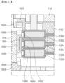
- FIG. 5 is a cross-sectional perspective view of the washing machine drive system according to one embodiment of the present disclosure.
- FIG. 6 is a partial cross-sectional perspective view of a clutch actuator, a clutch stator, and a rotor of the washing machine drive system according to one embodiment of the present disclosure.
- FIG. 7 is a view in which an upper carrier is removed in a planetary gear set of a washing machine drive system according to one embodiment of the present disclosure.
- FIG. 8 is a cross-sectional view of a partial configuration of the washing machine drive system according to one embodiment of the present disclosure.
- FIG. 9 is an enlarged view of the clutch actuator and the clutch stator region in a cross-section of the washing machine drive system according to one embodiment of the present disclosure.
- the washing machine drive system 100 may include an output shaft 110, a housing 120, a first bearing 130, a second bearing 140, a motor stator 150, a rotor 160, a planetary gear set 170, and a clutch 180, but some of these components may be excluded and additional components are not excluded.
- the output shaft 110 may be extended in an axial direction.
- the output shaft 110 may be coupled with the pulsator 20.
- the output shaft 110 may be rotatably coupled to the housing 120.
- the output shaft 110 may be bearing-coupled to the housing 120.
- the output shaft 110 may be coupled to the planetary gear set 170.
- the output shaft 110 may be spline-coupled to the carrier 179 of the planetary gear set 170.
- the spline refers to a groove or a groove cut into a shaft or a bore
- the spline-coupling may refer to a coupling that can rotate together while sliding in the axial direction.
- the output shaft 110 may rotate at the same speed as the carrier 179 of the planetary gear set 170.
- the axial direction may be interpreted as a vertical direction based on FIGS. 4 and 5 .
- the pulsator 20 may be coupled to the upper region of the output shaft 110.
- the central region of the output shaft 110 may be bearing-coupled to the housing 120.
- a first bearing 130 and a second bearing 140 may be arranged between the central region of the output shaft 110 and the housing 120.
- the lower region of the output shaft 110 may be arranged inside the rotor 160.
- the lower region of the output shaft 110 may be coupled to the planetary gear set 170.
- the diameter of the lower region of the output shaft 110 may be smaller than the diameter of the central region.
- the axial length of the lower region of the output shaft 110 may be shorter than the axial length of the central region of the output shaft 110.
- the output shaft 110 may include a first spline portion 112 formed on an outer peripheral surface.
- the first spline portion 112 may protrude outwardly from the outer peripheral surface of the output shaft 110.
- the first spline portion 112 may be arranged in a lower region of the output shaft 110.
- the first spline portion 112 may be spline-coupled to the second spline portion 1792 of the carrier 179 of the planetary gear set 170.
- the output shaft 110 may be rotatably coupled to the housing 120.
- the pulsator 20 may be arranged in the upper portion of the housing 120.
- the housing 120 may be coupled to the inner tub 10.
- the motor stator 150, the rotor 160, the planetary gear set 170, and the clutch 180 may be arranged in the lower portion of the housing 120.
- the housing 120 may be coupled to the motor stator 150.
- the housing 120 may be formed of a plastic material.
- the first bearing 130 may be arranged between the output shaft 110 and the housing 120.
- the first bearing 130 may bearing-couple the output shaft 110 to the housing 120.
- the first bearing 130 may rotatably couple the output shaft 110 to the housing 120.
- the first bearing 130 may extend in the circumferential direction.
- the first bearing 130 may be arranged above the second bearing 140.
- the second bearing 140 may be arranged between the output shaft 110 and the housing 120.
- the second bearing 140 may bearing-couple the output shaft 110 to the housing 120.
- the second bearing 140 may rotatably couple the output shaft 110 to the housing 120.
- the second bearing 140 may extend in the circumferential direction.
- the second bearing 140 may be arranged below the first bearing 130.
- the second bearing 140 may be arranged above the planetary gear set 170.
- the second bearing 140 may be arranged above the carrier 179 of the planetary gear set 170.
- the second bearing 140 may be arranged radially inwardly of the motor stator 150.
- the second bearing 140 may be arranged radially inwardly of the clutch stators 182, 184, 185, and 186.
- the motor stator 150 may be coupled to the housing 120.
- the motor stator 150 may be arranged inside the rotor 160.
- the motor stator 150 may face the rotor 160.
- the motor stator 150 may be arranged above the clutch 180.
- the motor stator 150 may be arranged above the clutch stators 182, 184, 185, and 186.
- the clutch stators 182, 184, 185, and 186 may be coupled to the motor stator 150.
- the motor stator 150 may include a motor coupling portion 152.
- the motor coupling portion 152 may be coupled to the housing 120.
- the motor coupling portion 152 may be arranged below the housing 120.
- a stator coupling portion 182 may be coupled to the motor couple portion 152.
- the motor couple portion 152 may be arranged above the stator coupling portion 182.
- the motor couple portion 152 may extend in a circumferential direction.
- a motor stator 154 may be arranged on an outer peripheral surface of the motor couple portion 152.
- the motor stator 150 may include the motor stator 154.
- the motor stator 154 may be disposed radially outwardly of the motor couple portion 152.
- the motor stator 154 may be coupled to the motor couple portion 152.
- the motor stator 154 may be disposed radially inwardly of the rotor 160.
- the motor stator 154 may face the rotor magnet 162.
- the motor stator 154 may include a plurality of motor stator units spaced apart in the circumferential direction.
- the motor stator unit may include a motor stator core formed on an outer peripheral surface of the motor couple portion 152, a motor coil wound around the motor stator core, and a yoke coupled to the motor stator core.
- the motor stator 154 may rotate the rotor magnet 162 through electromagnetic interaction.
- the rotor 160 may face the motor stator 150.
- the rotor 160 may be coupled with the planetary gear set 170.
- the rotor 160 may be coupled with a sun gear 172 of the planetary gear set 170. Therefore, the rotor 160 may supply a rotational force to the output shaft 110.
- the rotor 160 may include a rotor magnet 162.
- the rotor magnet 162 may be disposed in a rotor case 164.
- the rotor magnet 162 may be disposed on an inner peripheral surface of a cylindrical portion 1642 of the rotor case 164.
- the rotor magnet 162 may face the motor stator 150.
- the rotor magnet 162 may face the motor stator 154 of the motor stator 150. When current is supplied to the motor stator 154 of the motor stator 150, the rotor magnet 162 may rotate in one direction or the other direction due to electromagnetic interaction.
- the rotor magnet 162 may overlap a second coil 1864 and a third coil 1862 in a direction perpendicular to or horizontal to the output shaft 110.
- the rotor magnet 162 may not overlap the first coil 1866 in the direction perpendicular to or horizontal to the output shaft 110. Accordingly, the space efficiency of the rotor 160 and the motor stator 150 can be improved.
- the rotor magnet 162 may include a plurality of rotor magnet units spaced apart in the circumferential direction. Each of the plurality of rotor magnet units may face each of the plurality of motor stator units.
- the rotor 160 may include a rotor case 164.
- the rotor case 164 may include a disk portion 1644 sharing a center with the output shaft 110 and a cylindrical portion 1642 extending upwardly from the radial outer side of the disk portion 1644.
- a rotor magnet 162 may be arranged on an inner peripheral surface of a cylindrical portion 1642.
- a disk portion 1644 may be coupled with the planetary gear set 170.
- the disk portion 1644 may be coupled with the sun gear 172 of the planetary gear set 170.
- a fourth clutch portion 1646 may be formed in the disk portion 1644.
- the fourth clutch portion 1646 may be formed on an upper surface of the disk portion 1644.
- the fourth clutch portion 1646 may face a third clutch portion 1888 of clutch actuators 188 and 189.
- the fourth clutch portion 1646 may be engaged and coupled with the third clutch portion 1888 of the clutch actuators 188 and 189.
- the fourth clutch portion 1646 may extend in the circumferential direction.
- the fourth clutch portion 1646 may be formed of a plurality of protrusions spaced apart from each other in the circumferential direction.
- the motor stator 150 and the rotor 160 may be referred to as a "motor'.
- the planetary gear set 170 may be spline-coupled to the outer peripheral surface of the output shaft 110.
- the planetary gear set 170 may be coupled to the rotor 160.
- the planetary gear set 170 may rotate integrally with the rotor 160.
- the planetary gear set 170 may transmit the rotational force of the rotor 160 to the output shaft 110.
- the planetary gear set 170 may transmit the rotational force of the rotor 160 to the output shaft 110 by reducing the rotational force with a gear ratio of 1:1 or n:1.
- the clutch actuators 188 and 189 moves upward and is fixed to the clutch stators 182, 184, 185, and 186, a part of the planetary gear set 170 spline-coupled with the clutch actuators 188 and 189 is fixed, so that the rotational force of the rotor 160 may be transmitted to the output shaft 110 while being reduced with a gear ratio of n:1.
- a washing mode and a dehydration mode may be implemented without a stop motion between the end of the washing and the start of the dehydration.
- the planetary gear set 170 may include a sun gear 172, a plurality of pinion gears 174, a ring gear 176, a connecting portion 178, and a carrier 179.
- the sun gear 172 may be coupled to the rotor 160.
- the sun gear 172 may be coupled to the rotor case 164 of the rotor 160.
- the lower region of the sun gear 172 may be coupled to the radially inner region of the rotor case 164.
- the sun gear 172 may be coupled to the plurality of pinion gears 174.
- the upper region of the sun gear 172 may be coupled to the plurality of pinion gears 174.
- the outer peripheral surface of the sun gear 172 may be coupled to the plurality of pinion gears 174.
- the sun gear 172 may be bearing-coupled to the carrier 179 through a sun gear bearing 173.
- a first gear 1722 may be formed on the outer peripheral surface of the sun gear 172. In one embodiment of the present disclosure, the first gear 1722 is described as a spur gear, but the first gear 1722 may be changed to a helical gear.
- the plurality of pinion gears 174 may be spaced apart from each other in the circumferential direction.
- the outer peripheral surfaces of the plurality of pinion gears 174 may be coupled with the outer peripheral surfaces of the sun gear 172, respectively.
- a second gear 1742 may be formed on the outer peripheral surfaces of the plurality of pinion gears 174.
- the second gear 1742 is described as a spur gear, but alternatively, the second gear 1742 may be changed to a helical gear.
- the number of the plurality of pinion gears 174 is described as three, but is not limited thereto, and the number of the plurality of pinion gears 174 may be changed in various ways.
- the connecting portion 178 may be formed inside each of the plurality of pinion gears 174.
- the plurality of pinion gears 174 may be connected to the carrier 179 through the connecting portion 178.
- An inner peripheral surface of the ring gear 176 may be coupled with the plurality of pinion gears 174.
- a third gear 1762 may be formed on the inner peripheral surface of the ring gear 176.
- the third gear 1762 is described as a spur gear, but in other embodiments, the third gear 1762 may be changed to a helical gear.
- the outer peripheral surface of the ring gear 176 may be spline-coupled with the clutch actuators 188 and 189.
- a third spline portion 1764 may be formed on the outer peripheral surface of the ring gear 176.
- the third spline portion 1764 of the ring gear 176 may be spline-coupled with a fourth spline portion 1884 of the clutch actuators 188 and 189.
- the carrier 179 may be coupled with the plurality of pinion gears 174.
- the carrier 179 may be coupled with the plurality of pinion gears 174 through the connecting portion 178.
- the carrier 179 may be arranged on the plurality of pinion gears 174.
- the carrier 179 may be spline-coupled to the outer peripheral surface of the output shaft 110.
- a second spline portion 1792 may be formed on the inner peripheral surface of the carrier 179.
- the second spline portion 1792 may be spline-coupled with the first spline portion 112 of the output shaft 110.
- the carrier 179 may be bearing-coupled with the sun gear 172 through the sun gear bearing 173.
- the carrier 179 may be bearing-coupled with the ring gear 176 through the ring gear bearing 177. Therefore, the rotational speed of the carrier 179 and the rotational speed of the ring gear 176 may be made different, and the rotational speed of the carrier 179 and the rotational speed of the sun gear 172 may be made different, so that the rotational force of the rotor 160 may be reduced by the gear ratio of n:1 and transmitted to the output shaft 110.
- the ring gear bearing 177 may include a first ring gear bearing 1772 and a second ring gear bearing 1774 that are spaced apart in the vertical direction.
- the first ring gear bearing 1772 may be arranged above the plurality of pinion gears 174, and the second ring gear bearing 1774 may be arranged below the plurality of pinion gears 174.
- the sun gear bearing 173 may overlap the first coil 1866 and the second coil 1864 in the direction vertical or horizontal to the output shaft 110.
- the sun gear bearing 173 may include a first sun gear bearing 1732 and a second sun gear bearing 1734 that are spaced apart in a vertical direction.
- the vertical center regions of the plurality of pinion gears 174 may be arranged between the first coil 1866 and the second coil 1864 in a direction vertical or horizontal to the output shaft 110.
- the plurality of pinion gears 174 may overlap the first coil 1866 and the second coil 1864 in the direction perpendicular or horizontal to the output shaft 110.
- the plurality of pinion gears 174 may not overlap the third coil 1862 in the direction perpendicular or horizontal to the output shaft 110.
- the upper surface of the ring gear 176 may overlap the third coil 1862 in the direction perpendicular or horizontal to the output shaft 110.
- the lower surface of the ring gear 176 may be arranged below the first coil 1866 in a direction perpendicular or horizontal to the output shaft 110. Therefore, the size of the washing machine drive system 100 can be reduced.
- the clutch 180 may be arranged between the motor 150 and 160 and the planetary gear set 170. A portion of the clutch 180 may be spline-coupled to the planetary gear set 170, and another portion may be coupled to the motor stator 150. The clutch 180 may lock or unlock a portion of the planetary gear set 170. Accordingly, the clutch 180 may allow the planetary gear set 170 to transmit the rotational force of the rotor 160 to the output shaft 110 at a 1: 1 ratio, or to transmit the rotational force to the output shaft 110 while reducing the rotation force at a gear ratio of n:1.
- the clutch 180 may include the clutch stators 182, 184, 185, and 186 and clutch actuators 188 and 189.
- the clutch stators 182, 184, 185, and 186 may be coupled to the motor stator 150.
- the clutch stators 182, 184, 185, and 186 may be coupled to the motor couple portion 152.
- the clutch stators 182, 184, 185, and 186 may be coupled to the lower surface of the motor couple portion 152.
- the clutch stators 182, 184, 185, and 186 may be arranged between the planetary gear set 170 and the motor stator 150 in the direction perpendicular or horizontal to the output shaft 110.
- the clutch stators 182, 184, 185, and 186 may include a stator coupling portion 182, a clutch stator 184, an insulator 185, and a coil 186.
- the stator coupling portion 182 may be coupled to the lower surface of the motor couple portion 152.
- the clutch stator 184, the insulator 185, and the coil 186 may be coupled to the stator coupling portion 182.
- the stator coupling portion 182 may be formed of a plastic material.
- the stator coupling portion 182 may include a circumferential portion 1822 extending inwardly in a circumferential direction from an upper surface, and a second clutch portion 1824 formed on a lower surface of the circumferential portion 1822.
- the circumferential portion 1822 may extend in a circumferential direction.
- the circumferential portion 1822 may extend upwardly from the upper surface and inner peripheral surface of the stator coupling portion 182 and extend radially inwardly.
- the lower surface of the circumferential portion 1822 may face the clutch actuators 188 and 189.
- the second clutch portion 1824 may be vertically overlapped with the clutch actuators 188 and 189.
- the second clutch portion 1824 may face a first clutch portion 1886 of the clutch actuators 188 and 189.
- the second clutch portion 1824 may be engaged and coupled with the first clutch portion 1886 of the clutch actuators 188 and 189.
- the second clutch portion 1824 may be formed with a plurality of protrusions spaced apart from each other in the circumferential direction.
- the clutch stator 184 may be coupled to the stator coupling portion 182.
- the clutch stator 184 may be formed of a metal material.
- the insulator 185 and a coil 186 may be arranged in the clutch stator 184.
- the clutch stator 184 may include first to third cores 1842, 1844, and 1846 arranged in parallel in the vertical direction.
- the first to third cores 1842, 1844, and 1846 may be formed in the same shape, respectively.
- First to third insulators 1852, 1854, and 1856 and the first to third coils 1862, 1864, and 1866 may be arranged in the first to third cores 1842, 1844, and 1846.
- the insulator 185 may be arranged in the clutch stator 184.
- the insulator 185 may include first to third insulators 1852, 1854, and 1856 arranged in parallel in the vertical direction.
- the first to third insulators 1852, 1854, and 1856 may be arranged in the first to third cores 1842, 1844, and 1846.
- the coil 186 may be arranged in the clutch stator 184.
- the coil 186 may be arranged radially inwardly of the insulator 185.
- the coil 186 may include the first to third coils 1862, 1864, and 1866.
- the first to third coils 1862, 1864, and 1866 may be arranged in parallel in the vertical direction.
- the first to third coils 1862, 1864, and 1866 may be spaced apart from each other at equal intervals in the vertical direction.
- the first coil 1866 may be arranged in the first core 1846.
- the second coil 1864 may be arranged in the second core 1844.
- the third coil 1862 may be arranged in the third core 1846.
- the first to third coils 1862, 1864, and 1866 may each be formed in the same shape.
- the clutch actuators 188 and 189 When current is supplied to the first coil 1866, the clutch actuators 188 and 189 may move downward. In this case, the third clutch portion 1888 of the clutch actuators 188 and 189 is engaged and coupled with the fourth clutch portion 1646 of the rotor 160 so that the clutch actuators 188 and 189 may be fixed to the rotor 160. Since the planetary gear set 170 spline-coupled with the clutch actuators 188 and 189 rotates integrally with the rotor 160, the rotational force of the rotor 160 may be transmitted 1: 1 to the output shaft 110 to implement the dehydration mode.
- the clutch actuators 188 and 189 When current is supplied to the third coil 1862, the clutch actuators 188 and 189 may move upward. In this case, the first clutch portion 1886 of the clutch actuators 188 and 189 is engaged and coupled with the second clutch portion 1824 of the clutch stators 182, 184, 185, and 186 so that the clutch actuators 188 and 189 may be fixed to the clutch stators 182, 184, 185, and 186. Since the ring gear 176 of the planetary gear set 170 spline-coupled to the clutch actuators 188 and 189 is fixed, the rotational force of the rotor 160 may be reduced by a gear ratio of n:1 and transmitted to the output shaft 110 to implement the washing mode.
- the clutch actuators 188 and 189 may be decoupled from the rotor 160 or the clutch stators 182, 184, 185, and 186. Accordingly, the neutral mode of the clutch 180 is implemented, so that the reduction ratio may be applied while maintaining the rotation of the rotor 160. In addition, since the rotation of the rotor 160 is not stopped and the reduction ratio is applied to enter the initial dehydration mode, high torque may be generated.
- the first clutch portion 1886 may be formed on the upper surface of the clutch actuators 188 and 189.
- the first clutch portion 1886 may be formed on the upper surface of the clutch coupling portion 1882.
- the first clutch portion 1886 may be formed in a plurality of protrusion shapes spaced apart in the circumferential direction.
- the first clutch portion 1886 may face the second clutch portion 1824.
- the first clutch portion 1886 may be engaged and coupled with the second clutch portion 1824.
- the first clutch portion 1886 may be engaged and coupled with the second clutch portion 1824 so that the clutch actuators 188 and 189 may be fixed to the clutch stators 182, 184, 185, and 186. Accordingly, by coupling the clutch actuators 188 and 189 to the clutch stators 182, 184, 185, and 186, the rotation of the ring gear 176 spline-coupled with the clutch actuators 188 and 189 may be stopped.
- the vertical length of the clutch magnet 189 may be between 1.5 and 2.5 times the vertical length of each of the first to third coils 1862, 1864, and 1866.
- the vertical length of the clutch magnet 189 may be between 1.8 and 2.2 times the vertical length of each of the first to third coils 1862, 1864, and 1866.
- the vertical length of the clutch magnet 189 may be twice the vertical length of each of the first to third coils 1862, 1864, and 1866. Accordingly, while the positions of the three stable points can be stably determined, the efficiency of the clutch 180 can be improved.
- the vertical length of the clutch magnet 189 may be understood to mean the length in the up-down direction based on FIGS. 5 , 6 , 8 to 12 .
- the clutch magnet 189 When current is supplied to the second coil 1864, the clutch magnet 189 may overlap the second coil 1864 and the first to third cores 1842, 1844, and 1846 in the horizontal direction. When current is supplied to the second coil 1864, the vertical center region of the clutch magnet 189 may overlap the vertical center region of the second coil 1864 in the horizontal direction.
- the clutch magnet 189 When current is supplied to the third coil 1862, the clutch magnet 189 may overlap the second coil 1864, the third coil 1862, the second core 1844, and the third core 1842 in the horizontal direction. When current is supplied to the third coil 1862, the vertical center region of the clutch magnet 189 may overlap the lower region of the third coil 1862 in the horizontal direction.
- the lower region of the third coil 1862 may be interpreted as a region adjacent to the lower end or the lower surface of the third coil 1862.
- three stable points may be formed so that the position of the clutch actuators 188 and 189 may be maintained even when the supply of current to the first to third coils 1862, 1864, and 1866 is stopped.
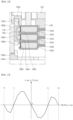
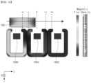
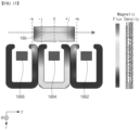
- the three stable points may be understood as the central region of the clutch magnet 189 being located at the -k, 0, and k points based on FIGS. 13 to 15 .
- FIGS. 10 to 12 are operation diagrams of the clutch actuator in the washing machine drive system according to one embodiment of the present disclosure.
- the clutch actuators 188 and 189 moves downward due to the electromagnetic interaction between the first coil 1866 and the clutch magnet 189.
- the third clutch portion 1888 of the clutch actuators 188 and 189 is engaged and coupled with the fourth clutch portion 1646 of the rotor 160. Since the ring gear 174 spline-coupled with the clutch actuators 188 and 189 rotate together with the rotor 160, the clutch 180 transmits the rotational force of the rotor 160 to the output shaft 110 1: 1 to implement the dehydration mode.
- the clutch actuators 188 and 189 moves to the region adjacent to the second coil 1864 due to the electromagnetic interaction between the second coil 1864 and the clutch magnet 189.
- the clutch actuators 188 and 189 are decoupled with the rotor 160 and the clutch stators 182, 184, 185, and 186 and implements the neutral mode, so that even when the rotor 160 rotates, the mode can be switched from the washing mode to the dehydration mode or from the dehydration mode to the washing mode.
- the clutch actuators 188 and 189 moves upward due to the electromagnetic interaction between the third coil 1862 and the clutch magnet 189.
- the first clutch portion 1886 of the clutch actuators 188 and 189 is engaged and coupled with the second clutch portion 1824 of the clutch stators 182, 184, 185, and 186. Since the ring gear 174 splined-coupled with the clutch actuators 188 and 189 is fixed, the planetary gear set 170 reduces the rotational force of the rotor 160 with a gear ratio of n:1 and transmits the reduced rotational force to the output shaft 110 to implement the washing mode.
- FIG. 13 is a graph illustrating a z-axis force according to the position of the clutch actuator of the washing machine drive system according to one embodiment of the present disclosure.
- FIGS. 14 to 16 are views illustrating a magnetic flux density distribution of the clutch stator according to the position of the clutch actuator of the washing machine drive system according to one embodiment of the present disclosure.
- FIG. 17 and FIG. 18 are graphs illustrating the z-axis force applied to the clutch magnet according to the position of the clutch magnet of the washing machine drive system according to one embodiment of the present disclosure.
- the size and arrangement of the detailed configuration of the clutch 180 according to one embodiment of the present disclosure can form three stable points, and thus, even when the supply of current to the first to third coils 1862, 1864, and 1866 is stopped, the positions of the clutch actuators 188 and 189 can be maintained.
Landscapes
- Engineering & Computer Science (AREA)
- Power Engineering (AREA)
- Textile Engineering (AREA)
- Connection Of Motors, Electrical Generators, Mechanical Devices, And The Like (AREA)
- Main Body Construction Of Washing Machines And Laundry Dryers (AREA)
Abstract
Description
- The present disclosure relates to a washing machine drive system, and more specifically, to a washing machine drive system having a clutch.
- A washing machine is driven in two main operating modes (washing mode, dehydration mode) with different operating conditions.
- In order to satisfy both of the above two main operating modes, the washing machine is provided with a planetary gear set and a clutch, and operates an output shaft with a low speed and high torque with a gear ratio of n:1 (washing mode), or operates the output shaft with a high speed and low torque with a gear ratio of 1: 1 (dehydration mode).
- Here, the output shaft refers to a shaft coupled to a drum to rotate the drum. The drum may be referred to as an "inner tub".
- That is, in a typical washing machine, after a washing mode or a rinsing mode is terminated, the motor is temporarily stopped and a draining operation is performed. And, after the draining operation is completed, an initial dehydration mode starts.
- However, since high torque is required to initially start wet laundry in the initial dehydration mode, the output shaft should be operated at low speed and high torque.
- Moreover, in order to start the dehydration mode after the initial dehydration mode is completed, the output shaft should be operated at high speed and low torque.
- Therefore, the washing machine drive system has components for changing a rotational force of a rotor shaft transmitted to the output shaft between the initial dehydration mode and the dehydration mode, such as a planetary gear set and a clutch.
- As an example of a related art related to the present disclosure, Korean Patent No.
KR10-1920812 - That is, in the case of the prior art, in an initial dehydration mode, the reduction coupling unit moves forward according to the operation of a lever of a lever unit, and accordingly, the teeth formed on a coupling cap of the reduction coupling unit engage with the teeth formed on the drum, so that the washing machine operates at low speed and high torque.
- In addition, in the dehydration mode, the reduction coupling unit moves backward according to the operation of the lever of the lever unit, and accordingly, the teeth formed on the coupling housing of the reduction coupling unit engage with the teeth formed on the rotor housing, so that the washing machine operates at high speed and low torque.
- However, according to the drive system disclosed in the prior patent, since the pinion gear equipped on the carrier of the reduction coupling unit should move axially with respect to the sun gear, only a spur gear, not a helical gear, can be used as the pinion gear and the sun gear, which causes a problem of noise.
- In addition, since the forward and backward movement of the reduction coupling unit is possible only when the motor is stopped, there is a problem that the motor should be stopped for mode switching.
- In addition, the sun gear equipped in the planetary gear set is mounted on the bearing on the output shaft, and the output shaft is supported by only one bearing.
- Therefore, in the initial dehydration mode, the planetary gear set acts as a support point, and the output shaft is supported by the planetary gear set and the bearing, but in the dehydration mode, the rotor, the planetary gear set, and the output shaft operate as one, and the output shaft is supported by only one bearing, so there is a problem of low durability in the dehydration mode in which the operation is performed at high speed and low torque.
- An object of the present disclosure seeks to solve is to provide a washing machine drive system that can apply a reduction ratio while maintaining the rotation of a rotor by implementing a neutral mode of a clutch.
- In addition, an object of the present disclosure is to provide a washing machine drive system that can generate high torque by applying a reduction ratio without stopping the rotation of the rotor.
- In addition, an object of the present disclosure is to provide a washing machine drive system that can apply a helical gear to the detailed configuration of a planetary gear set.
- In addition, an object of the present disclosure is to provide a washing machine drive system that can improve space efficiency while making the rotational speed of a sun gear and the rotational speed of a carrier different.
- In addition, an object of the present disclosure is to provide a washing machine drive system that can improve space efficiency while making the rotational speed of a carrier and the rotational speed of a ring gear different.
- In addition, an object of the present disclosure is to provide a washing machine drive system that can stop the rotation of a ring gear that is spline-coupled with the clutch actuator by coupling a clutch actuator to a clutch stator.
- In addition, an object of the present disclosure is to provide a washing machine drive system that can rotate the ring gear that is spline-coupled with the clutch actuator together with the rotor by coupling the clutch actuator to the rotor.
- In addition, an object of the present disclosure is to provide a washing machine drive system that can reduce power consumption by maintaining the position of the clutch actuator even when the clutch actuator is moved in a vertical direction and the supply of current is stopped.
- In addition, an object of the present disclosure is to provide a washing machine drive system that can improve space efficiency and reduce size.
- In addition, an object of the present disclosure is to provide a washing machine drive system that can maintain the position of the clutch actuator even when the supply of current to first to third coils is stopped by forming three stable points.
- According to the present disclosure, there is provided a washing machine drive system including: a housing; a motor stator coupled to the housing; a rotor facing the motor stator; an output shaft bearing-coupled to the housing; a planetary gear set coupled to the rotor and spline-coupled to an outer peripheral surface of the output shaft; a clutch stator coupled to the motor stator; and a clutch actuator spline-coupled to an outer peripheral surface of the planetary gear set so as to be vertically movable and facing the clutch stator.
- In this case, the clutch stator includes first to third coils arranged in parallel in a vertical direction, the clutch actuator is fixed to the rotor and transmits rotational force of the rotor to the output shaft at a 1:1 ratio when current is supplied to the first coil, the clutch actuator is fixed to the clutch stator, reduces the rotational force of the rotor at a gear ratio of n: 1, and transmits the reduced rotational force to the output shaft when current is supplied to the third coil, and the clutch actuator is disengaged from the rotor or the clutch stator when current is supplied to the second coil.
- Accordingly, a neutral mode of the clutch is implemented, and thus, a reduction ratio can be applied while maintaining the rotation of the rotor.
- In addition, since the reduction ratio is applied without stopping the rotation of the rotor, an initial dehydration mode can be entered, so high torque can be generated.
the planetary gear set may include a sun gear coupled to the rotor, a plurality of pinion gears coupled with an outer surface of the sun gear and spaced apart in a circumferential direction, a ring gear whose inner peripheral surface is coupled with the plurality of pinion gears and whose outer peripheral surface is spline-coupled with the clutch actuator, and a carrier coupled with the plurality of pinion gears and spline-coupled to the outer peripheral surface of the output shaft. - Accordingly, since the pinion gear does not need to move axially with respect to the sun gear, the helical gear can be applied to detailed configurations of the planetary gear set.
- The washing machine drive system may further include a sun gear bearing arranged between the carrier and the sun gear.
- Accordingly, space efficiency can be improved while making the rotational speed of the sun gear and the rotational speed of the carrier different.
- The sun gear bearing may overlap the first and second coils in a direction perpendicular to the output shaft.
- Therefore, it is possible to reduce the size of the washing machine drive system.
- The washing machine drive system may further include a ring gear bearing arranged between the carrier and the ring gear.
- Accordingly, space efficiency can be improved while making the rotational speed of the carrier and the rotational speed of the ring gear different.
- A vertical center area of the plurality of pinion gears may be arranged between the first coil and the second coil in a direction perpendicular to the output axis.
- The plurality of pinion gears may overlap the first and second coils in a direction perpendicular to the output shaft, and may not overlap the third coil in a direction perpendicular to the output shaft.
- An upper surface of the ring gear may overlap the third coil in a direction perpendicular to the output shaft, and a lower surface of the ring gear may be arranged below the first coil in the direction perpendicular to the output shaft.
- Therefore, it is possible to reduce the size of the washing machine drive system.
- Moreover, the clutch actuator may include a first clutch portion formed on an upper surface of the clutch, the clutch stator may include a second clutch portion formed on a surface facing the upper surface of the clutch actuator, and the first clutch portion may be engaged and coupled with the second clutch portion when current is supplied to the third coil.
- Therefore, by coupling the clutch actuator to the clutch stator, the rotation of the ring gear spline-coupled to the clutch actuator can be stopped.
- The clutch actuator may include a third clutch portion formed on a lower surface of the clutch actuator, the rotor may include a fourth clutch portion formed on a surface facing the lower surface of the clutch actuator, and the third clutch portion may be engaged and coupled with the fourth clutch portion when current is supplied to the first coil.
- Therefore, by coupling the clutch actuator to the rotor, the ring gear spline-coupled to the clutch actuator can rotate together with the rotor.
- The clutch actuator may include a clutch coupling portion spline-connected to the planetary gear set and a clutch magnet disposed in the clutch coupling portion and facing the clutch stator.
- In this case, the coupling of the clutch actuator and the rotor may be maintained when current is supplied to the first coil and then the supply of current is stopped, the coupling of the clutch actuator and the clutch stator may be maintained when current is supplied to the third coil and then the supply of current is stopped, and decoupling of the clutch actuator and the rotor or the clutch stator may be maintained when current is supplied to the second coil and then the supply of current is stopped.
- Accordingly, power consumption can be reduced because the position of the clutch actuator is maintained even when the clutch actuator is moved in the vertical direction and the supply of current is stopped.
- A vertical length of the clutch magnet may be between 1.8 and 2.2 times a vertical length of each of the first to third coils.
- Moreover, the clutch stator may include a stator coupling portion coupled to the motor stator, and first to third cores arranged in the stator coupling portion and arranged in parallel in a vertical direction.
- In this case, the first coil may be arranged in the first core, the second coil may be arranged in the second core, the third coil may be arranged in the third core, and the first to third cores may be each formed in the same shape, and the first to third coils may be each formed in the same shape.
- The stator coupling portion may include a circumferential portion extending inwardly in the circumferential direction from an upper surface of the stator coupling portion, a second clutch portion may be arranged on a lower surface of the circumferential portion, and a second clutch portion may overlap the clutch actuator in a vertical direction.
- Accordingly, it is possible to improve space efficiency of the washing machine drive system.
- The clutch actuator may include a clutch coupling portion spline-coupled to the planetary gear set, and a clutch magnet disposed in the clutch coupling portion and facing the clutch stator.
- In this case, the clutch magnet may overlap the first coil, the second coil, the first core, and the second core in a horizontal direction when current is supplied to the first coil, the clutch magnet may overlap the second coil and the first to third cores in the horizontal direction when current is supplied to the second coil, and the clutch magnet may overlap the second coil, the third coil, the second core, and the third core in the horizontal direction when current is supplied to the third coil.
- Moreover, the vertical center region of the clutch magnet may overlap the upper region of the first coil in the horizontal direction when current is supplied to the first coil, the vertical center region of the clutch magnet may overlap the vertical center region of the second coil in the horizontal direction when current is supplied to the second coil, and the vertical center region of the clutch magnet may overlap the lower region of the third coil in the horizontal direction when current is supplied to the third coil.
- Accordingly, three stable points are formed so that the position of the clutch actuator can be maintained even when the supply of current to the first to third coils is stopped.
- The clutch actuator and the clutch stator may be disposed between the planetary gear set and the motor stator in a direction perpendicular to the output shaft.
- The rotor may include a rotor case including a disk portion sharing a center with the output shaft and a cylindrical portion extending upward from a radially outer side of the disk portion, and a rotor magnet disposed in the cylindrical portion and facing the motor stator.
- In this case, the rotor magnet may overlap the second and third coils in a direction perpendicular to the output shaft and may not overlap the first coil in the direction perpendicular to the output shaft.
- Therefore, it is possible to improve of space efficiency of the rotor and the motor stator.
- According to the present disclosure, it is possible to provide a washing machine drive system that can apply a reduction ratio while maintaining the rotation of a rotor by implementing a neutral mode of a clutch.
- According to the present disclosure, it is possible to provide a washing machine drive system that can generate high torque by applying a reduction ratio without stopping the rotation of the rotor.
- According to the present disclosure, it is possible to provide a washing machine drive system that can apply a helical gear to the detailed configuration of a planetary gear set.
- According to the present disclosure, it is possible to provide a washing machine drive system that can improve space efficiency while making the rotational speed of a sun gear and the rotational speed of a carrier different.
- According to the present disclosure, it is possible to a washing machine drive system that can improve space efficiency while making the rotational speed of a carrier and the rotational speed of a ring gear different.
- According to the present disclosure, it is possible to provide a washing machine drive system that can stop the rotation of a ring gear that is spline-coupled with the clutch actuator by coupling a clutch actuator to a clutch stator.
- According to the present disclosure, it is possible to provide a washing machine drive system that can rotate the ring gear that is spline-coupled with the clutch actuator together with the rotor by coupling the clutch actuator to the rotor.
- According to the present disclosure, it is possible to provide a washing machine drive system that can reduce power consumption by maintaining the position of the clutch actuator even when the clutch actuator is moved in a vertical direction and the supply of current is stopped.
- According to the present disclosure, it is possible to provide a washing machine drive system that can improve space efficiency and reduce size.
- According to the present disclosure, it is possible to provide a washing machine drive system that can maintain the position of the clutch actuator even when the supply of current to first to third coils is stopped by forming three stable points.
-
-
FIGS. 1 and2 are perspective views of a tub and a washing machine drive system of a washing machine according to one embodiment of the present disclosure. -
FIG. 3 is a perspective view of the washing machine drive system according to one embodiment of the present disclosure. -
FIG. 4 is an exploded perspective view of the washing machine drive system according to one embodiment of the present disclosure. -
FIG. 5 is a cross-sectional perspective view of the washing machine drive system according to one embodiment of the present disclosure. -
FIG. 6 is a partial cross-sectional perspective view of a clutch actuator, a clutch stator, and a rotor of the washing machine drive system according to one embodiment of the present disclosure. -
FIG. 7 is a view in which an upper carrier is removed in a planetary gear set of a washing machine drive system according to one embodiment of the present disclosure. -
FIG. 8 is a cross-sectional view of a partial configuration of the washing machine drive system according to one embodiment of the present disclosure. -
FIG. 9 is an enlarged view of the clutch actuator and the clutch stator region in a cross-section of the washing machine drive system according to one embodiment of the present disclosure. -
FIGS. 10 to 12 are operation diagrams of a clutch actuator in the washing machine drive system according to one embodiment of the present disclosure. -
FIG. 13 is a graph illustrating a z-axis force according to a position of the clutch actuator in the washing machine drive system according to one embodiment of the present disclosure. -
FIGS. 14 to 16 are views illustrating a magnetic flux density distribution of the clutch stator according to the position of the clutch actuator in the washing machine drive system according to one embodiment of the present disclosure. -
FIG. 17 andFIG. 18 are graphs illustrating the z-axis force applied to the clutch magnet according to the position of the clutch magnet of the washing machine drive system according to one embodiment of the present disclosure. - Hereinafter, embodiments disclosed in this disclosure will be described in detail with reference to the attached drawings, and regardless of the drawing symbols, identical or similar components will be given the same reference numerals and redundant descriptions thereof will be omitted.
- When describing the embodiments disclosed in this disclosure, when it is mentioned that a component is "coupled" or "connected" to another component, it should be understood that it may be directly connected or connected to the other component, but other components may exist therebetween.
- In addition, when describing the embodiments disclosed in this disclosure, in a case where it is determined that a specific description of a related known technology may obscure the gist of the embodiments disclosed in this disclosure, the detailed description thereof will be omitted. In addition, the attached drawings are only intended to facilitate easy understanding of the embodiments disclosed in the present disclosure, and the technical ideas disclosed in the present disclosure are not limited by the attached drawings, and should be understood to include all modifications, equivalents, or substitutes included in the scope of the ideas and technologies of the present disclosure.
- Meanwhile, the term such as the disclosure may be replaced with terms such as document, specification, and description.
-
FIG. 1 andFIG. 2 are perspective views of a tub and a washing machine drive system of a washing machine according to one embodiment of the present disclosure. - Referring to
FIG. 1 andFIG. 2 , the washing machine according to one embodiment of the present disclosure may include aninner tub 10, apulsator 20, and a washingmachine drive system 100, but may be implemented excluding some of the configurations thereof, and does not exclude additional configurations. - The washing machine according to one embodiment of the present disclosure may be a top loading type washing machine in which a rotation center of the
inner tub 10 is formed in a direction perpendicular to a bottom and is designed to allow laundry to be loaded from the upper side, and a front loading type washing machine in which the rotation center of theinner tub 10 is formed in a direction horizontal to the bottom or inclined in a direction that decreases toward the rear end and is designed to allow laundry to be loaded from the front. - The
inner tub 10 may have a cylindrical shape with an open top or front. Thepulsator 20 may be arranged on a bottom surface of theinner tub 10. Theinner tub 10 may be formed of a plastic material. Thepulsator 20 may be connected to anoutput shaft 110 of the washingmachine drive system 100. The washingmachine drive system 100 may be coupled to theinner tub 10 to rotate thepulsator 20. -
FIG. 3 is a perspective view of the washing machine drive system according to one embodiment of the present disclosure.FIG. 4 is an exploded perspective view of the washing machine drive system according to one embodiment of the present disclosure.FIG. 5 is a cross-sectional perspective view of the washing machine drive system according to one embodiment of the present disclosure.FIG. 6 is a partial cross-sectional perspective view of a clutch actuator, a clutch stator, and a rotor of the washing machine drive system according to one embodiment of the present disclosure.FIG. 7 is a view in which an upper carrier is removed in a planetary gear set of a washing machine drive system according to one embodiment of the present disclosure.FIG. 8 is a cross-sectional view of a partial configuration of the washing machine drive system according to one embodiment of the present disclosure.FIG. 9 is an enlarged view of the clutch actuator and the clutch stator region in a cross-section of the washing machine drive system according to one embodiment of the present disclosure. - Referring to
FIGS. 3 to 9 , the washingmachine drive system 100 according to one embodiment of the present disclosure may include anoutput shaft 110, ahousing 120, afirst bearing 130, asecond bearing 140, amotor stator 150, arotor 160, a planetary gear set 170, and a clutch 180, but some of these components may be excluded and additional components are not excluded. - The
output shaft 110 may be extended in an axial direction. Theoutput shaft 110 may be coupled with thepulsator 20. Theoutput shaft 110 may be rotatably coupled to thehousing 120. Theoutput shaft 110 may be bearing-coupled to thehousing 120. Theoutput shaft 110 may be coupled to the planetary gear set 170. Theoutput shaft 110 may be spline-coupled to thecarrier 179 of the planetary gear set 170. Here, the spline refers to a groove or a groove cut into a shaft or a bore, and the spline-coupling may refer to a coupling that can rotate together while sliding in the axial direction. Theoutput shaft 110 may rotate at the same speed as thecarrier 179 of the planetary gear set 170. In one embodiment of the present disclosure, the axial direction may be interpreted as a vertical direction based onFIGS. 4 and5 . - The
pulsator 20 may be coupled to the upper region of theoutput shaft 110. The central region of theoutput shaft 110 may be bearing-coupled to thehousing 120. Afirst bearing 130 and asecond bearing 140 may be arranged between the central region of theoutput shaft 110 and thehousing 120. - The lower region of the
output shaft 110 may be arranged inside therotor 160. The lower region of theoutput shaft 110 may be coupled to the planetary gear set 170. The diameter of the lower region of theoutput shaft 110 may be smaller than the diameter of the central region. The axial length of the lower region of theoutput shaft 110 may be shorter than the axial length of the central region of theoutput shaft 110. - The
output shaft 110 may include afirst spline portion 112 formed on an outer peripheral surface. Thefirst spline portion 112 may protrude outwardly from the outer peripheral surface of theoutput shaft 110. Thefirst spline portion 112 may be arranged in a lower region of theoutput shaft 110. Thefirst spline portion 112 may be spline-coupled to thesecond spline portion 1792 of thecarrier 179 of the planetary gear set 170. - The
output shaft 110 may be rotatably coupled to thehousing 120. Thepulsator 20 may be arranged in the upper portion of thehousing 120. Thehousing 120 may be coupled to theinner tub 10. Themotor stator 150, therotor 160, the planetary gear set 170, and the clutch 180 may be arranged in the lower portion of thehousing 120. Thehousing 120 may be coupled to themotor stator 150. Thehousing 120 may be formed of a plastic material. - The
first bearing 130 may be arranged between theoutput shaft 110 and thehousing 120. Thefirst bearing 130 may bearing-couple theoutput shaft 110 to thehousing 120. Thefirst bearing 130 may rotatably couple theoutput shaft 110 to thehousing 120. Thefirst bearing 130 may extend in the circumferential direction. Thefirst bearing 130 may be arranged above thesecond bearing 140. - The
second bearing 140 may be arranged between theoutput shaft 110 and thehousing 120. Thesecond bearing 140 may bearing-couple theoutput shaft 110 to thehousing 120. Thesecond bearing 140 may rotatably couple theoutput shaft 110 to thehousing 120. Thesecond bearing 140 may extend in the circumferential direction. Thesecond bearing 140 may be arranged below thefirst bearing 130. Thesecond bearing 140 may be arranged above the planetary gear set 170. Thesecond bearing 140 may be arranged above thecarrier 179 of the planetary gear set 170. Thesecond bearing 140 may be arranged radially inwardly of themotor stator 150. Thesecond bearing 140 may be arranged radially inwardly of theclutch stators - The
motor stator 150 may be coupled to thehousing 120. Themotor stator 150 may be arranged inside therotor 160. Themotor stator 150 may face therotor 160. Themotor stator 150 may be arranged above the clutch 180. Themotor stator 150 may be arranged above theclutch stators clutch stators motor stator 150. - The
motor stator 150 may include amotor coupling portion 152. Themotor coupling portion 152 may be coupled to thehousing 120. Themotor coupling portion 152 may be arranged below thehousing 120. Astator coupling portion 182 may be coupled to themotor couple portion 152. Themotor couple portion 152 may be arranged above thestator coupling portion 182. Themotor couple portion 152 may extend in a circumferential direction. Amotor stator 154 may be arranged on an outer peripheral surface of themotor couple portion 152. - The
motor stator 150 may include themotor stator 154. Themotor stator 154 may be disposed radially outwardly of themotor couple portion 152. Themotor stator 154 may be coupled to themotor couple portion 152. Themotor stator 154 may be disposed radially inwardly of therotor 160. Themotor stator 154 may face therotor magnet 162. Themotor stator 154 may include a plurality of motor stator units spaced apart in the circumferential direction. The motor stator unit may include a motor stator core formed on an outer peripheral surface of themotor couple portion 152, a motor coil wound around the motor stator core, and a yoke coupled to the motor stator core. Themotor stator 154 may rotate therotor magnet 162 through electromagnetic interaction. - The
rotor 160 may face themotor stator 150. Therotor 160 may be coupled with the planetary gear set 170. Therotor 160 may be coupled with asun gear 172 of the planetary gear set 170. Therefore, therotor 160 may supply a rotational force to theoutput shaft 110. - The
rotor 160 may include arotor magnet 162. Therotor magnet 162 may be disposed in arotor case 164. Therotor magnet 162 may be disposed on an inner peripheral surface of acylindrical portion 1642 of therotor case 164. Therotor magnet 162 may face themotor stator 150. Therotor magnet 162 may face themotor stator 154 of themotor stator 150. When current is supplied to themotor stator 154 of themotor stator 150, therotor magnet 162 may rotate in one direction or the other direction due to electromagnetic interaction. - The
rotor magnet 162 may overlap asecond coil 1864 and athird coil 1862 in a direction perpendicular to or horizontal to theoutput shaft 110. Therotor magnet 162 may not overlap thefirst coil 1866 in the direction perpendicular to or horizontal to theoutput shaft 110. Accordingly, the space efficiency of therotor 160 and themotor stator 150 can be improved. - The
rotor magnet 162 may include a plurality of rotor magnet units spaced apart in the circumferential direction. Each of the plurality of rotor magnet units may face each of the plurality of motor stator units. - The
rotor 160 may include arotor case 164. Therotor case 164 may include adisk portion 1644 sharing a center with theoutput shaft 110 and acylindrical portion 1642 extending upwardly from the radial outer side of thedisk portion 1644. Arotor magnet 162 may be arranged on an inner peripheral surface of acylindrical portion 1642. Adisk portion 1644 may be coupled with the planetary gear set 170. Thedisk portion 1644 may be coupled with thesun gear 172 of the planetary gear set 170. A fourthclutch portion 1646 may be formed in thedisk portion 1644. The fourthclutch portion 1646 may be formed on an upper surface of thedisk portion 1644. The fourthclutch portion 1646 may face a thirdclutch portion 1888 ofclutch actuators clutch portion 1646 may be engaged and coupled with the thirdclutch portion 1888 of theclutch actuators clutch portion 1646 may extend in the circumferential direction. The fourthclutch portion 1646 may be formed of a plurality of protrusions spaced apart from each other in the circumferential direction. - The
motor stator 150 and therotor 160 may be referred to as a "motor'. - The planetary gear set 170 may be spline-coupled to the outer peripheral surface of the
output shaft 110. The planetary gear set 170 may be coupled to therotor 160. The planetary gear set 170 may rotate integrally with therotor 160. The planetary gear set 170 may transmit the rotational force of therotor 160 to theoutput shaft 110. - Specifically, according to the vertical movement of the
clutch actuators rotor 160 to theoutput shaft 110 by reducing the rotational force with a gear ratio of 1:1 or n:1. For example, when theclutch actuators clutch stators clutch actuators rotor 160 may be transmitted to theoutput shaft 110 while being reduced with a gear ratio of n:1. In contrast, when theclutch actuators rotor 160, theclutch actuators rotor 160 as a whole, so that the rotational force of therotor 160 may be transmitted to theoutput shaft 110 in a 1:1 ratio. Accordingly, a washing mode and a dehydration mode may be implemented without a stop motion between the end of the washing and the start of the dehydration. - The planetary gear set 170 may include a
sun gear 172, a plurality of pinion gears 174, aring gear 176, a connectingportion 178, and acarrier 179. - The
sun gear 172 may be coupled to therotor 160. Thesun gear 172 may be coupled to therotor case 164 of therotor 160. The lower region of thesun gear 172 may be coupled to the radially inner region of therotor case 164. Thesun gear 172 may be coupled to the plurality of pinion gears 174. The upper region of thesun gear 172 may be coupled to the plurality of pinion gears 174. The outer peripheral surface of thesun gear 172 may be coupled to the plurality of pinion gears 174. Thesun gear 172 may be bearing-coupled to thecarrier 179 through asun gear bearing 173. Afirst gear 1722 may be formed on the outer peripheral surface of thesun gear 172. In one embodiment of the present disclosure, thefirst gear 1722 is described as a spur gear, but thefirst gear 1722 may be changed to a helical gear. - The plurality of pinion gears 174 may be spaced apart from each other in the circumferential direction. The outer peripheral surfaces of the plurality of pinion gears 174 may be coupled with the outer peripheral surfaces of the
sun gear 172, respectively. Asecond gear 1742 may be formed on the outer peripheral surfaces of the plurality of pinion gears 174. In one embodiment of the present disclosure, thesecond gear 1742 is described as a spur gear, but alternatively, thesecond gear 1742 may be changed to a helical gear. - In one embodiment of the present disclosure, the number of the plurality of pinion gears 174 is described as three, but is not limited thereto, and the number of the plurality of pinion gears 174 may be changed in various ways.
- The connecting
portion 178 may be formed inside each of the plurality of pinion gears 174. The plurality of pinion gears 174 may be connected to thecarrier 179 through the connectingportion 178. - An inner peripheral surface of the
ring gear 176 may be coupled with the plurality of pinion gears 174. Athird gear 1762 may be formed on the inner peripheral surface of thering gear 176. In one embodiment of the present disclosure, thethird gear 1762 is described as a spur gear, but in other embodiments, thethird gear 1762 may be changed to a helical gear. - The outer peripheral surface of the
ring gear 176 may be spline-coupled with theclutch actuators third spline portion 1764 may be formed on the outer peripheral surface of thering gear 176. Thethird spline portion 1764 of thering gear 176 may be spline-coupled with afourth spline portion 1884 of theclutch actuators - The
carrier 179 may be coupled with the plurality of pinion gears 174. Thecarrier 179 may be coupled with the plurality of pinion gears 174 through the connectingportion 178. Thecarrier 179 may be arranged on the plurality of pinion gears 174. - The
carrier 179 may be spline-coupled to the outer peripheral surface of theoutput shaft 110. Asecond spline portion 1792 may be formed on the inner peripheral surface of thecarrier 179. Thesecond spline portion 1792 may be spline-coupled with thefirst spline portion 112 of theoutput shaft 110. - The
carrier 179 may be bearing-coupled with thesun gear 172 through thesun gear bearing 173. Thecarrier 179 may be bearing-coupled with thering gear 176 through thering gear bearing 177. Therefore, the rotational speed of thecarrier 179 and the rotational speed of thering gear 176 may be made different, and the rotational speed of thecarrier 179 and the rotational speed of thesun gear 172 may be made different, so that the rotational force of therotor 160 may be reduced by the gear ratio of n:1 and transmitted to theoutput shaft 110. - The ring gear bearing 177 may include a first
ring gear bearing 1772 and a secondring gear bearing 1774 that are spaced apart in the vertical direction. The firstring gear bearing 1772 may be arranged above the plurality of pinion gears 174, and the secondring gear bearing 1774 may be arranged below the plurality of pinion gears 174. - The sun gear bearing 173 may overlap the
first coil 1866 and thesecond coil 1864 in the direction vertical or horizontal to theoutput shaft 110. The sun gear bearing 173 may include a firstsun gear bearing 1732 and a secondsun gear bearing 1734 that are spaced apart in a vertical direction. The vertical center regions of the plurality of pinion gears 174 may be arranged between thefirst coil 1866 and thesecond coil 1864 in a direction vertical or horizontal to theoutput shaft 110. The plurality of pinion gears 174 may overlap thefirst coil 1866 and thesecond coil 1864 in the direction perpendicular or horizontal to theoutput shaft 110. The plurality of pinion gears 174 may not overlap thethird coil 1862 in the direction perpendicular or horizontal to theoutput shaft 110. The upper surface of thering gear 176 may overlap thethird coil 1862 in the direction perpendicular or horizontal to theoutput shaft 110. The lower surface of thering gear 176 may be arranged below thefirst coil 1866 in a direction perpendicular or horizontal to theoutput shaft 110. Therefore, the size of the washingmachine drive system 100 can be reduced. - The clutch 180 may be arranged between the
motor motor stator 150. The clutch 180 may lock or unlock a portion of the planetary gear set 170. Accordingly, the clutch 180 may allow the planetary gear set 170 to transmit the rotational force of therotor 160 to theoutput shaft 110 at a 1: 1 ratio, or to transmit the rotational force to theoutput shaft 110 while reducing the rotation force at a gear ratio of n:1. The clutch 180 may include theclutch stators clutch actuators - The
clutch stators motor stator 150. Theclutch stators motor couple portion 152. Theclutch stators motor couple portion 152. Theclutch stators motor stator 150 in the direction perpendicular or horizontal to theoutput shaft 110. Theclutch stators stator coupling portion 182, aclutch stator 184, aninsulator 185, and acoil 186. - The
stator coupling portion 182 may be coupled to the lower surface of themotor couple portion 152. Theclutch stator 184, theinsulator 185, and thecoil 186 may be coupled to thestator coupling portion 182. Thestator coupling portion 182 may be formed of a plastic material. Thestator coupling portion 182 may include acircumferential portion 1822 extending inwardly in a circumferential direction from an upper surface, and a secondclutch portion 1824 formed on a lower surface of thecircumferential portion 1822. - The
circumferential portion 1822 may extend in a circumferential direction. Thecircumferential portion 1822 may extend upwardly from the upper surface and inner peripheral surface of thestator coupling portion 182 and extend radially inwardly. The lower surface of thecircumferential portion 1822 may face theclutch actuators - The second
clutch portion 1824 may be vertically overlapped with theclutch actuators clutch portion 1824 may face a firstclutch portion 1886 of theclutch actuators clutch portion 1824 may be engaged and coupled with the firstclutch portion 1886 of theclutch actuators clutch portion 1824 may be formed with a plurality of protrusions spaced apart from each other in the circumferential direction. - The
clutch stator 184 may be coupled to thestator coupling portion 182. Theclutch stator 184 may be formed of a metal material. Theinsulator 185 and acoil 186 may be arranged in theclutch stator 184. Theclutch stator 184 may include first tothird cores third cores third insulators third coils third cores - The
insulator 185 may be arranged in theclutch stator 184. Theinsulator 185 may include first tothird insulators third insulators third cores - The
coil 186 may be arranged in theclutch stator 184. Thecoil 186 may be arranged radially inwardly of theinsulator 185. Thecoil 186 may include the first tothird coils third coils third coils first coil 1866 may be arranged in thefirst core 1846. Thesecond coil 1864 may be arranged in thesecond core 1844. Thethird coil 1862 may be arranged in thethird core 1846. The first tothird coils - When current is supplied to the
first coil 1866, theclutch actuators clutch portion 1888 of theclutch actuators clutch portion 1646 of therotor 160 so that theclutch actuators rotor 160. Since the planetary gear set 170 spline-coupled with theclutch actuators rotor 160, the rotational force of therotor 160 may be transmitted 1: 1 to theoutput shaft 110 to implement the dehydration mode. - When current is supplied to the
third coil 1862, theclutch actuators clutch portion 1886 of theclutch actuators clutch portion 1824 of theclutch stators clutch actuators clutch stators ring gear 176 of the planetary gear set 170 spline-coupled to theclutch actuators rotor 160 may be reduced by a gear ratio of n:1 and transmitted to theoutput shaft 110 to implement the washing mode. - When current is supplied to the
second coil 1864, theclutch actuators rotor 160 or theclutch stators rotor 160. In addition, since the rotation of therotor 160 is not stopped and the reduction ratio is applied to enter the initial dehydration mode, high torque may be generated. - The
clutch actuators clutch actuators clutch actuators clutch stators clutch actuators motor stator 150 in the direction perpendicular or horizontal to theoutput shaft 110. Theclutch actuators clutch coupling portion 1882, a firstclutch portion 1886, a thirdclutch portion 1888, afourth spline portion 1884, and aclutch magnet 189. - The
clutch coupling portion 1882 may extend in the circumferential direction. The cross section of theclutch coupling portion 1882 may be formed in a "U" shape. Theclutch coupling portion 1882 may be spline-coupled to the planetary gear set 170. Theclutch coupling portion 1882 may be spline-coupled to thering gear 176 of the planetary gear set 170. Theclutch coupling portion 1882 may face theclutch stators clutch coupling portion 1882 may face the secondclutch portion 1824. The lower surface of theclutch coupling portion 1882 may face the fourthclutch portion 1646. - The first
clutch portion 1886 may be formed on the upper surface of theclutch actuators clutch portion 1886 may be formed on the upper surface of theclutch coupling portion 1882. The firstclutch portion 1886 may be formed in a plurality of protrusion shapes spaced apart in the circumferential direction. The firstclutch portion 1886 may face the secondclutch portion 1824. The firstclutch portion 1886 may be engaged and coupled with the secondclutch portion 1824. Specifically, when current is supplied to thethird coil 1862 and theclutch actuators clutch portion 1886 may be engaged and coupled with the secondclutch portion 1824 so that theclutch actuators clutch stators clutch actuators clutch stators ring gear 176 spline-coupled with theclutch actuators - The third
clutch portion 1888 may be formed on the lower surface of theclutch actuators clutch portion 1888 may be formed on the lower surface of theclutch coupling portion 1882. The thirdclutch portion 188 may be formed as a plurality of protrusion shapes spaced apart in the circumferential direction. The thirdclutch portion 1888 may face the fourthclutch portion 1646. The thirdclutch portion 1888 may be engaged and coupled with the fourthclutch portion 1646. Specifically, when current is supplied to thefirst coil 1866 and theclutch actuators clutch portion 1888 may be engaged and coupled with the fourthclutch portion 1646, so that theclutch actuators rotor 160. Therefore, thering gear 176 spline-coupled with theclutch actuators rotor 160. - The
fourth spline portion 1884 may be formed on the inner peripheral surface of theclutch coupling portion 1882. Thefourth spline portion 1884 may be spline-coupled with the planetary gear set 170. Thefourth spline portion 1884 may be spline-coupled with thethird spline portion 1764 of thering gear 176. - The
clutch magnet 189 may be arranged in theclutch coupling portion 1882. Theclutch magnet 189 may be arranged in a groove formed on the outer peripheral surface of theclutch coupling portion 1882. Theclutch magnet 189 may extend in the circumferential direction. Theclutch magnet 189 may face theclutch stators clutch magnet 189 may face the first tothird coils clutch magnet 189 may move in the vertical direction by electromagnetic interaction with the first tothird coils clutch magnet 189 may include a plurality of magnetic poles arranged in the vertical direction. The vertical length of theclutch magnet 189 may be between 1.5 and 2.5 times the vertical length of each of the first tothird coils clutch magnet 189 may be between 1.8 and 2.2 times the vertical length of each of the first tothird coils clutch magnet 189 may be twice the vertical length of each of the first tothird coils clutch magnet 189 may be understood to mean the length in the up-down direction based onFIGS. 5 ,6 ,8 to 12 . - When current is supplied to the
first coil 1866, theclutch magnet 189 may overlap thefirst coil 1866, thesecond coil 1864, thefirst core 1846, and thesecond core 1844 in the horizontal direction. When current is supplied to thefirst coil 1866, the vertical center region of theclutch magnet 189 may be overlap the upper region of thefirst coil 1866 in the horizontal direction. Here, the upper region of thefirst coil 1866 may be interpreted as meaning a region adjacent to the upper end or the upper surface of thefirst coil 1866. In the present disclosure, the meaning of overlapping in the horizontal direction may be understood as overlapping in a left-right direction based onFIGS. 5 ,6 ,8 to 12 . - When current is supplied to the
second coil 1864, theclutch magnet 189 may overlap thesecond coil 1864 and the first tothird cores second coil 1864, the vertical center region of theclutch magnet 189 may overlap the vertical center region of thesecond coil 1864 in the horizontal direction. - When current is supplied to the
third coil 1862, theclutch magnet 189 may overlap thesecond coil 1864, thethird coil 1862, thesecond core 1844, and thethird core 1842 in the horizontal direction. When current is supplied to thethird coil 1862, the vertical center region of theclutch magnet 189 may overlap the lower region of thethird coil 1862 in the horizontal direction. Here, the lower region of thethird coil 1862 may be interpreted as a region adjacent to the lower end or the lower surface of thethird coil 1862. - Accordingly, three stable points may be formed so that the position of the
clutch actuators third coils clutch magnet 189 being located at the -k, 0, and k points based onFIGS. 13 to 15 . - Specifically, when the supply of current is stopped after the supply of current to the
first coil 1866, the coupling of theclutch actuators rotor 160 may be maintained. When the current supply to thethird coil 1862 is stopped after the current supply is supplied, the coupling between theclutch actuators clutch stators second coil 1864 is stopped after the current supply is supplied, the decoupling between theclutch actuators rotor 160 or theclutch stators - Accordingly, even when the
clutch actuators clutch actuators -
FIGS. 10 to 12 are operation diagrams of the clutch actuator in the washing machine drive system according to one embodiment of the present disclosure. - Referring to
FIG. 10 , when current is supplied to thefirst coil 1866, theclutch actuators first coil 1866 and theclutch magnet 189. In this case, the thirdclutch portion 1888 of theclutch actuators clutch portion 1646 of therotor 160. Since thering gear 174 spline-coupled with theclutch actuators rotor 160, the clutch 180 transmits the rotational force of therotor 160 to theoutput shaft 110 1: 1 to implement the dehydration mode. - Referring to
FIG. 11 , when current is supplied to thesecond coil 1864, theclutch actuators second coil 1864 due to the electromagnetic interaction between thesecond coil 1864 and theclutch magnet 189. In this case, theclutch actuators rotor 160 and theclutch stators rotor 160 rotates, the mode can be switched from the washing mode to the dehydration mode or from the dehydration mode to the washing mode. - Referring to
FIG. 12 , when current is supplied to thethird coil 1862, theclutch actuators third coil 1862 and theclutch magnet 189. In this case, the firstclutch portion 1886 of theclutch actuators clutch portion 1824 of theclutch stators ring gear 174 splined-coupled with theclutch actuators rotor 160 with a gear ratio of n:1 and transmits the reduced rotational force to theoutput shaft 110 to implement the washing mode. -
FIG. 13 is a graph illustrating a z-axis force according to the position of the clutch actuator of the washing machine drive system according to one embodiment of the present disclosure.FIGS. 14 to 16 are views illustrating a magnetic flux density distribution of the clutch stator according to the position of the clutch actuator of the washing machine drive system according to one embodiment of the present disclosure. - Referring to
FIGS. 13 and14 , it can be seen that when the vertical center region of theclutch magnet 189 is arranged at a -k position, the z-axis force applied to theclutch magnet 189 by the magnetic flux density of the first tothird cores clutch magnet 189 is 0. - Referring to
FIGS. 13 and15 , it can be seen that when the vertical center region of theclutch magnet 189 is arranged at an O position, the z-axis force applied to theclutch magnet 189 by the magnetic flux density of the first tothird cores clutch magnet 189 is 0. - Referring to
FIG. 13 andFIG. 16 , when the vertical center region of theclutch magnet 189 is arranged at a +k position, it can be seen that the z-axis force applied to theclutch magnet 189 by the magnetic flux density of the first tothird cores clutch magnet 189 is 0. -
FIG. 17 andFIG. 18 are graphs illustrating the z-axis force applied to the clutch magnet according to the position of the clutch magnet of the washing machine drive system according to one embodiment of the present disclosure. - Referring to
FIGS. 14 and17 , when the mode is switched fromMode 1 to Mode 2, current is supplied to thesecond coil 1864. Specifically, when current is supplied to thesecond coil 1864 in the dehydration mode where theclutch magnet 189 is on the left side in the z-axis direction vertically downward, force is applied to theclutch magnet 189 to the right side in the z-axis direction. In this case, since the position of theclutch magnet 189 moves to the center in the z-axis direction (center in the vertical direction), the neutral mode can be implemented. In particular, when the position of the z-axis center area (center area in the vertical direction) of theclutch magnet 189 is at a position of 0, the z-axis force applied to theclutch magnet 189 becomes 0, so that it can be positioned at a stable point without immediately switching to the washing mode. - Referring to
FIGS. 15 and17 , when the mode is switched from Mode 2 toMode 1, current is supplied to thefirst coil 1866. Specifically, when current is supplied to thefirst coil 1866 in the neutral mode where theclutch magnet 189 is at the center of the z-axis direction (center in the vertical direction), a force is applied to theclutch magnet 189 to the left in the z-axis direction. In this case, since the position of theclutch magnet 189 moves to the left in the z-axis direction (downward in the vertical direction), the dehydration mode can be implemented. - Referring to
FIG. 15 andFIG. 18 , when the mode is switched from Mode 2 to Mode 3, current is supplied to thethird coil 1862. Specifically, when current is supplied to thethird coil 1862 in the neutral mode where theclutch magnet 189 is at the center of the z-axis direction (the center in the vertical direction), a force is applied to theclutch magnet 189 to the right in the z-axis direction. In this case, since the position of theclutch magnet 189 moves to the right in the z-axis direction (upward in the vertical direction), the washing mode can be implemented. - Referring to
FIG. 16 andFIG. 18 , when the mode is switched Mode 3 to Mode 2, current is supplied to thesecond coil 1864. Specifically, when current is supplied to thesecond coil 1864 in the washing mode where theclutch magnet 189 is to the right in the z-axis direction (upward in the vertical direction), a force is applied to theclutch magnet 189 to the left in the z-axis direction. In this case, since the position of theclutch magnet 189 moves to the left in the z-axis direction (downward in the vertical direction), the neutral mode can be implemented. In particular, when the position of the z-axis central region (central region in the vertical direction) of theclutch magnet 189 is at a position of 0, the z-axis force applied to theclutch magnet 189 becomes 0, so that the mode does not immediately go to the dehydration mode but can be positioned at a stable point. - That is, the size and arrangement of the detailed configuration of the clutch 180 according to one embodiment of the present disclosure can form three stable points, and thus, even when the supply of current to the first to
third coils clutch actuators - The embodiments or other embodiments of the present disclosure described above are not mutually exclusive or distinct. The embodiments or other embodiments of the present disclosure described above may be combined or used in combination with each other in their respective configurations or functions.
- For example, it means that A configuration described in a specific embodiment and/or the drawings and B configuration described in another embodiment and/or the drawings can be coupled. That is, even when the coupling between the configurations is not directly described, it means that the coupling is possible except in cases where the coupling is described as impossible.
- The above detailed description should not be construed as limiting in all respects and should be considered exemplary. The scope of the present disclosure should be determined by a reasonable interpretation of the appended claims, and all changes within the equivalent scope of the present disclosure are included in the scope of the present disclosure.
Claims (18)
- A washing machine drive system comprising:a housing;a motor stator coupled to the housing;a rotor facing the motor stator;an output shaft bearing-coupled to the housing;a planetary gear set coupled to the rotor and spline-coupled to an outer peripheral surface of the output shaft;a clutch stator coupled to the motor stator; anda clutch actuator spline-coupled to an outer peripheral surface of the planetary gear set so as to be vertically movable and facing the clutch stator,wherein the clutch stator includes first to third coils arranged in parallel in a vertical direction,the clutch actuator is fixed to the rotor and transmits rotational force of the rotor to the output shaft at a 1:1 ratio when current is supplied to the first coil,the clutch actuator is fixed to the clutch stator, reduces the rotational force of the rotor at a gear ratio of n: 1, and transmits the reduced rotational force to the output shaft when current is supplied to the third coil, andthe clutch actuator is disengaged from the rotor or the clutch stator when current is supplied to the second coil.
- The washing machine drive system of claim 1, wherein the planetary gear set includesa sun gear coupled to the rotor,a plurality of pinion gears coupled with an outer surface of the sun gear and spaced apart in a circumferential direction,a ring gear whose inner peripheral surface is coupled with the plurality of pinion gears and whose outer peripheral surface is spline-coupled with the clutch actuator, anda carrier coupled with the plurality of pinion gears and spline-coupled to the outer peripheral surface of the output shaft.
- The washing machine drive system of claim 2, further comprising a sun gear bearing arranged between the carrier and the sun gear.
- The washing machine drive system of claim 3, wherein the sun gear bearing overlaps the first and second coils in a direction perpendicular to the output shaft.
- The washing machine drive system of claim 2, further comprising a ring gear bearing arranged between the carrier and the ring gear.
- The washing machine drive system of claim 2, wherein a vertical center area of the plurality of pinion gears is arranged between the first coil and the second coil in a direction perpendicular to the output axis.
- The washing machine drive system of claim 2, wherein the plurality of pinion gears overlap the first and second coils in a direction perpendicular to the output shaft, and do not overlap the third coil in a direction perpendicular to the output shaft.
- The washing machine drive system of claim 2, wherein an upper surface of the ring gear overlaps the third coil in a direction perpendicular to the output shaft, and
a lower surface of the ring gear is arranged below the first coil in the direction perpendicular to the output shaft. - The washing machine drive system of claim 1, wherein the clutch actuator includes a first clutch portion formed on an upper surface of the clutch,the clutch stator includes a second clutch portion formed on a surface facing the upper surface of the clutch actuator, andthe first clutch portion is engaged and coupled with the second clutch portion when current is supplied to the third coil.
- The washing machine drive system of claim 1, wherein the clutch actuator includes a third clutch portion formed on a lower surface of the clutch actuator,the rotor includes a fourth clutch portion formed on a surface facing the lower surface of the clutch actuator, andthe third clutch portion is engaged and coupled with the fourth clutch portion when current is supplied to the first coil.
- The washing machine drive system of claim 1, wherein the clutch actuator includes a clutch coupling portion spline-connected to the planetary gear set and a clutch magnet disposed in the clutch coupling portion and facing the clutch stator,the coupling of the clutch actuator and the rotor is maintained when current is supplied to the first coil and then the supply of current is stopped,the coupling of the clutch actuator and the clutch stator is maintained when current is supplied to the third coil and then the supply of current is stopped, anddecoupling of the clutch actuator and the rotor or the clutch stator is maintained when current is supplied to the second coil and then the supply of current is stopped.
- The washing machine drive system of claim 11, wherein a vertical length of the clutch magnet is between 1.8 and 2.2 times a vertical length of each of the first to third coils.
- The washing machine drive system of claim 1, wherein the clutch stator includes a stator coupling portion coupled to the motor stator, and first to third cores arranged in the stator coupling portion and arranged in parallel in a vertical direction,the first coil is arranged in the first core, the second coil is arranged in the second core, the third coil is arranged in the third core, andthe first to third cores are each formed in the same shape, and the first to third coils are each formed in the same shape.
- The washing machine drive system of claim 13, wherein the stator coupling portion includes a circumferential portion extending inwardly in the circumferential direction from an upper surface of the stator coupling portion,a second clutch portion is arranged on a lower surface of the circumferential portion, anda second clutch portion overlaps the clutch actuator in a vertical direction.
- The washing machine drive system of claim 13, wherein the clutch actuator includes a clutch coupling portion spline-coupled to the planetary gear set, and a clutch magnet disposed in the clutch coupling portion and facing the clutch stator,the clutch magnet overlaps the first coil, the second coil, the first core, and the second core in a horizontal direction when current is supplied to the first coil,the clutch magnet overlaps the second coil and the first to third cores in the horizontal direction when current is supplied to the second coil, andthe clutch magnet overlaps the second coil, the third coil, the second core, and the third core in the horizontal direction when current is supplied to the third coil.
- The washing machine drive system of claim 13, wherein the clutch actuator includes a clutch coupling portion spline-coupled to the planetary gear set, and a clutch magnet disposed in the clutch coupling portion and facing the clutch stator,a vertical center region of the clutch magnet overlaps an upper region of the first coil in a horizontal direction when current is supplied to the first coil,the vertical center region of the clutch magnet overlaps a vertical center region of the second coil in the horizontal direction when current is supplied to the second coil, andthe vertical center region of the clutch magnet overlaps a lower region of the third coil in the horizontal direction when current is supplied to the third coil.
- The washing machine drive system of claim 1, wherein the clutch actuator and the clutch stator are disposed between the planetary gear set and the motor stator in a direction perpendicular to the output shaft.
- The washing machine drive system of claim 1, wherein the rotor includes a rotor case including a disk portion sharing a center with the output shaft and a cylindrical portion extending upward from a radially outer side of the disk portion, and a rotor magnet disposed in the cylindrical portion and facing the motor stator, and
the rotor magnet overlaps the second and third coils in a direction perpendicular to the output shaft and does not overlap the first coil in the direction perpendicular to the output shaft.
Applications Claiming Priority (1)
| Application Number | Priority Date | Filing Date | Title |
|---|---|---|---|
| PCT/KR2023/006749 WO2024237374A1 (en) | 2023-05-18 | 2023-05-18 | Washing machine driving system |
Publications (3)
| Publication Number | Publication Date |
|---|---|
| EP4488438A1 true EP4488438A1 (en) | 2025-01-08 |
| EP4488438A4 EP4488438A4 (en) | 2025-04-23 |
| EP4488438B1 EP4488438B1 (en) | 2025-08-13 |
Family
ID=93519825
Family Applications (1)
| Application Number | Title | Priority Date | Filing Date |
|---|---|---|---|
| EP23921579.1A Active EP4488438B1 (en) | 2023-05-18 | 2023-05-18 | Washing machine driving system |
Country Status (4)
| Country | Link |
|---|---|
| EP (1) | EP4488438B1 (en) |
| KR (1) | KR102949869B1 (en) |
| CN (1) | CN119343492A (en) |
| WO (1) | WO2024237374A1 (en) |
Cited By (1)
| Publication number | Priority date | Publication date | Assignee | Title |
|---|---|---|---|---|
| US20240235350A9 (en) * | 2022-10-21 | 2024-07-11 | Lg Electronics Inc. | Drive system of a washing machine |
Family Cites Families (9)
| Publication number | Priority date | Publication date | Assignee | Title |
|---|---|---|---|---|
| KR101700763B1 (en) * | 2010-12-02 | 2017-01-31 | 엘지전자 주식회사 | Washing machine |
| CN105579636B (en) * | 2013-10-02 | 2018-11-27 | 阿莫泰克有限公司 | Washing machine motor and washing machine having same |
| KR101920812B1 (en) | 2017-05-12 | 2018-11-21 | 뉴모텍(주) | Deceleration Coupling Unit for Direct Driven Driving Apparatus of Washing Machine |
| KR102081359B1 (en) * | 2018-09-21 | 2020-02-25 | 엘지전자 주식회사 | Washing machine |
| US11365504B2 (en) * | 2019-01-17 | 2022-06-21 | Samsung Electronics Co., Ltd. | Washing machine |
| JP7338979B2 (en) * | 2019-02-05 | 2023-09-05 | 三星電子株式会社 | Drive unit for washing machine |
| JP2023020905A (en) * | 2021-07-30 | 2023-02-09 | 三星電子株式会社 | Driving device and washing machine |
| JP7776948B2 (en) | 2021-07-30 | 2025-11-27 | 三星電子株式会社 | Actuators and drive units for washing machines |
| WO2023008794A1 (en) * | 2021-07-30 | 2023-02-02 | 삼성전자 주식회사 | Washing machine |
-
2023
- 2023-05-18 KR KR1020247014962A patent/KR102949869B1/en active Active
- 2023-05-18 CN CN202380024105.8A patent/CN119343492A/en active Pending
- 2023-05-18 WO PCT/KR2023/006749 patent/WO2024237374A1/en not_active Ceased
- 2023-05-18 EP EP23921579.1A patent/EP4488438B1/en active Active
Cited By (2)
| Publication number | Priority date | Publication date | Assignee | Title |
|---|---|---|---|---|
| US20240235350A9 (en) * | 2022-10-21 | 2024-07-11 | Lg Electronics Inc. | Drive system of a washing machine |
| US12451779B2 (en) * | 2022-10-21 | 2025-10-21 | Lg Electronics Inc. | Drive system of a washing machine |
Also Published As
| Publication number | Publication date |
|---|---|
| WO2024237374A1 (en) | 2024-11-21 |
| EP4488438B1 (en) | 2025-08-13 |
| EP4488438A4 (en) | 2025-04-23 |
| CN119343492A (en) | 2025-01-21 |
| KR102949869B1 (en) | 2026-04-08 |
| KR20240167425A (en) | 2024-11-26 |
Similar Documents
| Publication | Publication Date | Title |
|---|---|---|
| US10214846B2 (en) | Washing machine driving device, washing machine having same, and control method therefor | |
| US11525204B2 (en) | Washing machine driving device, and washing machine and driving method using same | |
| CN102948048B (en) | Twin-stator/double-rotor motor and direct-connection drive unit for washing machine using it | |
| US7642684B2 (en) | Nested variable field dynamoelectric machine | |
| EP4488438A1 (en) | Washing machine driving system | |
| JP2013046519A (en) | Rotating electric machine | |
| KR101639022B1 (en) | Rdum driving apparatus, drum washing machine having the same and driving method thereof | |
| EP4357510B1 (en) | Drive system of a washing machine | |
| US11746459B2 (en) | Washing machine | |
| EP4357511A1 (en) | Drum washing machine | |
| KR102816543B1 (en) | Drive system of a washing machine | |
| KR102815288B1 (en) | Drive system of a washing machine | |
| EP4650507A1 (en) | Drum rotating device for laundry care apparatus | |
| EP4650506A1 (en) | Drum rotating device for laundry care apparatus | |
| JP2021007673A (en) | Washing machine | |
| JP4007375B2 (en) | Rotating electric machine | |
| JP2025093788A (en) | Gear motor series, robot series | |
| JP2022156873A (en) | Vehicular driving device | |
| JP2010213472A (en) | Motor drive device | |
| JP2016208658A (en) | Rotary electric machine with reduction gear | |
| JP2015217921A (en) | Motor-generator apparatus |
Legal Events
| Date | Code | Title | Description |
|---|---|---|---|
| STAA | Information on the status of an ep patent application or granted ep patent |
Free format text: STATUS: UNKNOWN |
|
| STAA | Information on the status of an ep patent application or granted ep patent |
Free format text: STATUS: THE INTERNATIONAL PUBLICATION HAS BEEN MADE |
|
| PUAI | Public reference made under article 153(3) epc to a published international application that has entered the european phase |
Free format text: ORIGINAL CODE: 0009012 |
|
| STAA | Information on the status of an ep patent application or granted ep patent |
Free format text: STATUS: REQUEST FOR EXAMINATION WAS MADE |
|
| 17P | Request for examination filed |
Effective date: 20240824 |
|
| AK | Designated contracting states |
Kind code of ref document: A1 Designated state(s): AL AT BE BG CH CY CZ DE DK EE ES FI FR GB GR HR HU IE IS IT LI LT LU LV MC ME MK MT NL NO PL PT RO RS SE SI SK SM TR |
|
| A4 | Supplementary search report drawn up and despatched |
Effective date: 20250324 |
|
| RIC1 | Information provided on ipc code assigned before grant |
Ipc: H02K 7/11 20060101ALI20250318BHEP Ipc: H02K 7/108 20060101ALI20250318BHEP Ipc: D06F 37/40 20060101ALI20250318BHEP Ipc: D06F 37/30 20200101AFI20250318BHEP |
|
| GRAP | Despatch of communication of intention to grant a patent |
Free format text: ORIGINAL CODE: EPIDOSNIGR1 |
|
| STAA | Information on the status of an ep patent application or granted ep patent |
Free format text: STATUS: GRANT OF PATENT IS INTENDED |
|
| RIC1 | Information provided on ipc code assigned before grant |
Ipc: H02K 7/116 20060101ALI20250423BHEP Ipc: H02K 7/11 20060101ALI20250423BHEP Ipc: H02K 7/108 20060101ALI20250423BHEP Ipc: D06F 37/40 20060101ALI20250423BHEP Ipc: D06F 37/30 20200101AFI20250423BHEP |
|
| INTG | Intention to grant announced |
Effective date: 20250513 |
|
| GRAS | Grant fee paid |
Free format text: ORIGINAL CODE: EPIDOSNIGR3 |
|
| GRAA | (expected) grant |
Free format text: ORIGINAL CODE: 0009210 |
|
| STAA | Information on the status of an ep patent application or granted ep patent |
Free format text: STATUS: THE PATENT HAS BEEN GRANTED |
|
| AK | Designated contracting states |
Kind code of ref document: B1 Designated state(s): AL AT BE BG CH CY CZ DE DK EE ES FI FR GB GR HR HU IE IS IT LI LT LU LV MC ME MK MT NL NO PL PT RO RS SE SI SK SM TR |
|
| DAV | Request for validation of the european patent (deleted) | ||
| DAX | Request for extension of the european patent (deleted) | ||
| REG | Reference to a national code |
Ref country code: GB Ref legal event code: FG4D |
|
| REG | Reference to a national code |
Ref country code: CH Ref legal event code: EP |
|
| REG | Reference to a national code |
Ref country code: DE Ref legal event code: R096 Ref document number: 602023005760 Country of ref document: DE |
|
| REG | Reference to a national code |
Ref country code: IE Ref legal event code: FG4D |
|
| REG | Reference to a national code |
Ref country code: NL Ref legal event code: MP Effective date: 20250813 |
|
| PG25 | Lapsed in a contracting state [announced via postgrant information from national office to epo] |
Ref country code: IS Free format text: LAPSE BECAUSE OF FAILURE TO SUBMIT A TRANSLATION OF THE DESCRIPTION OR TO PAY THE FEE WITHIN THE PRESCRIBED TIME-LIMIT Effective date: 20251213 |
|
| PG25 | Lapsed in a contracting state [announced via postgrant information from national office to epo] |
Ref country code: NO Free format text: LAPSE BECAUSE OF FAILURE TO SUBMIT A TRANSLATION OF THE DESCRIPTION OR TO PAY THE FEE WITHIN THE PRESCRIBED TIME-LIMIT Effective date: 20251113 |
|
| REG | Reference to a national code |
Ref country code: LT Ref legal event code: MG9D |
|
| PG25 | Lapsed in a contracting state [announced via postgrant information from national office to epo] |
Ref country code: PT Free format text: LAPSE BECAUSE OF FAILURE TO SUBMIT A TRANSLATION OF THE DESCRIPTION OR TO PAY THE FEE WITHIN THE PRESCRIBED TIME-LIMIT Effective date: 20251215 |
|
| PG25 | Lapsed in a contracting state [announced via postgrant information from national office to epo] |
Ref country code: FI Free format text: LAPSE BECAUSE OF FAILURE TO SUBMIT A TRANSLATION OF THE DESCRIPTION OR TO PAY THE FEE WITHIN THE PRESCRIBED TIME-LIMIT Effective date: 20250813 |
|
| PG25 | Lapsed in a contracting state [announced via postgrant information from national office to epo] |
Ref country code: HR Free format text: LAPSE BECAUSE OF FAILURE TO SUBMIT A TRANSLATION OF THE DESCRIPTION OR TO PAY THE FEE WITHIN THE PRESCRIBED TIME-LIMIT Effective date: 20250813 Ref country code: NL Free format text: LAPSE BECAUSE OF FAILURE TO SUBMIT A TRANSLATION OF THE DESCRIPTION OR TO PAY THE FEE WITHIN THE PRESCRIBED TIME-LIMIT Effective date: 20250813 |
|
| PG25 | Lapsed in a contracting state [announced via postgrant information from national office to epo] |
Ref country code: GR Free format text: LAPSE BECAUSE OF FAILURE TO SUBMIT A TRANSLATION OF THE DESCRIPTION OR TO PAY THE FEE WITHIN THE PRESCRIBED TIME-LIMIT Effective date: 20251114 |
|
| PG25 | Lapsed in a contracting state [announced via postgrant information from national office to epo] |
Ref country code: SE Free format text: LAPSE BECAUSE OF FAILURE TO SUBMIT A TRANSLATION OF THE DESCRIPTION OR TO PAY THE FEE WITHIN THE PRESCRIBED TIME-LIMIT Effective date: 20250813 |
|
| PG25 | Lapsed in a contracting state [announced via postgrant information from national office to epo] |
Ref country code: LV Free format text: LAPSE BECAUSE OF FAILURE TO SUBMIT A TRANSLATION OF THE DESCRIPTION OR TO PAY THE FEE WITHIN THE PRESCRIBED TIME-LIMIT Effective date: 20250813 |
|
| PG25 | Lapsed in a contracting state [announced via postgrant information from national office to epo] |
Ref country code: PL Free format text: LAPSE BECAUSE OF FAILURE TO SUBMIT A TRANSLATION OF THE DESCRIPTION OR TO PAY THE FEE WITHIN THE PRESCRIBED TIME-LIMIT Effective date: 20250813 Ref country code: BG Free format text: LAPSE BECAUSE OF FAILURE TO SUBMIT A TRANSLATION OF THE DESCRIPTION OR TO PAY THE FEE WITHIN THE PRESCRIBED TIME-LIMIT Effective date: 20250813 |
|
| PG25 | Lapsed in a contracting state [announced via postgrant information from national office to epo] |
Ref country code: RS Free format text: LAPSE BECAUSE OF FAILURE TO SUBMIT A TRANSLATION OF THE DESCRIPTION OR TO PAY THE FEE WITHIN THE PRESCRIBED TIME-LIMIT Effective date: 20251113 |
|
| PG25 | Lapsed in a contracting state [announced via postgrant information from national office to epo] |
Ref country code: ES Free format text: LAPSE BECAUSE OF FAILURE TO SUBMIT A TRANSLATION OF THE DESCRIPTION OR TO PAY THE FEE WITHIN THE PRESCRIBED TIME-LIMIT Effective date: 20250813 |
|
| REG | Reference to a national code |
Ref country code: AT Ref legal event code: MK05 Ref document number: 1824752 Country of ref document: AT Kind code of ref document: T Effective date: 20250813 |
|
| PG25 | Lapsed in a contracting state [announced via postgrant information from national office to epo] |
Ref country code: SM Free format text: LAPSE BECAUSE OF FAILURE TO SUBMIT A TRANSLATION OF THE DESCRIPTION OR TO PAY THE FEE WITHIN THE PRESCRIBED TIME-LIMIT Effective date: 20250813 |
|
| PG25 | Lapsed in a contracting state [announced via postgrant information from national office to epo] |
Ref country code: DK Free format text: LAPSE BECAUSE OF FAILURE TO SUBMIT A TRANSLATION OF THE DESCRIPTION OR TO PAY THE FEE WITHIN THE PRESCRIBED TIME-LIMIT Effective date: 20250813 |
|
| PG25 | Lapsed in a contracting state [announced via postgrant information from national office to epo] |
Ref country code: AT Free format text: LAPSE BECAUSE OF FAILURE TO SUBMIT A TRANSLATION OF THE DESCRIPTION OR TO PAY THE FEE WITHIN THE PRESCRIBED TIME-LIMIT Effective date: 20250813 |
|
| PG25 | Lapsed in a contracting state [announced via postgrant information from national office to epo] |
Ref country code: CZ Free format text: LAPSE BECAUSE OF FAILURE TO SUBMIT A TRANSLATION OF THE DESCRIPTION OR TO PAY THE FEE WITHIN THE PRESCRIBED TIME-LIMIT Effective date: 20250813 |
|
| PG25 | Lapsed in a contracting state [announced via postgrant information from national office to epo] |
Ref country code: SK Free format text: LAPSE BECAUSE OF FAILURE TO SUBMIT A TRANSLATION OF THE DESCRIPTION OR TO PAY THE FEE WITHIN THE PRESCRIBED TIME-LIMIT Effective date: 20250813 Ref country code: EE Free format text: LAPSE BECAUSE OF FAILURE TO SUBMIT A TRANSLATION OF THE DESCRIPTION OR TO PAY THE FEE WITHIN THE PRESCRIBED TIME-LIMIT Effective date: 20250813 |