EP4488417A2 - Carbon dioxide recycling system - Google Patents
Carbon dioxide recycling system Download PDFInfo
- Publication number
- EP4488417A2 EP4488417A2 EP24181599.2A EP24181599A EP4488417A2 EP 4488417 A2 EP4488417 A2 EP 4488417A2 EP 24181599 A EP24181599 A EP 24181599A EP 4488417 A2 EP4488417 A2 EP 4488417A2
- Authority
- EP
- European Patent Office
- Prior art keywords
- exchange membrane
- cathode
- half cell
- aqueous solution
- carbon dioxide
- Prior art date
- Legal status (The legal status is an assumption and is not a legal conclusion. Google has not performed a legal analysis and makes no representation as to the accuracy of the status listed.)
- Pending
Links
Images




Classifications
-
- C—CHEMISTRY; METALLURGY
- C25—ELECTROLYTIC OR ELECTROPHORETIC PROCESSES; APPARATUS THEREFOR
- C25B—ELECTROLYTIC OR ELECTROPHORETIC PROCESSES FOR THE PRODUCTION OF COMPOUNDS OR NON-METALS; APPARATUS THEREFOR
- C25B15/00—Operating or servicing cells
- C25B15/08—Supplying or removing reactants or electrolytes; Regeneration of electrolytes
-
- C—CHEMISTRY; METALLURGY
- C25—ELECTROLYTIC OR ELECTROPHORETIC PROCESSES; APPARATUS THEREFOR
- C25B—ELECTROLYTIC OR ELECTROPHORETIC PROCESSES FOR THE PRODUCTION OF COMPOUNDS OR NON-METALS; APPARATUS THEREFOR
- C25B1/00—Electrolytic production of inorganic compounds or non-metals
-
- C—CHEMISTRY; METALLURGY
- C25—ELECTROLYTIC OR ELECTROPHORETIC PROCESSES; APPARATUS THEREFOR
- C25B—ELECTROLYTIC OR ELECTROPHORETIC PROCESSES FOR THE PRODUCTION OF COMPOUNDS OR NON-METALS; APPARATUS THEREFOR
- C25B1/00—Electrolytic production of inorganic compounds or non-metals
- C25B1/01—Products
- C25B1/02—Hydrogen or oxygen
- C25B1/04—Hydrogen or oxygen by electrolysis of water
-
- C—CHEMISTRY; METALLURGY
- C25—ELECTROLYTIC OR ELECTROPHORETIC PROCESSES; APPARATUS THEREFOR
- C25B—ELECTROLYTIC OR ELECTROPHORETIC PROCESSES FOR THE PRODUCTION OF COMPOUNDS OR NON-METALS; APPARATUS THEREFOR
- C25B1/00—Electrolytic production of inorganic compounds or non-metals
- C25B1/01—Products
- C25B1/23—Carbon monoxide or syngas
-
- C—CHEMISTRY; METALLURGY
- C25—ELECTROLYTIC OR ELECTROPHORETIC PROCESSES; APPARATUS THEREFOR
- C25B—ELECTROLYTIC OR ELECTROPHORETIC PROCESSES FOR THE PRODUCTION OF COMPOUNDS OR NON-METALS; APPARATUS THEREFOR
- C25B3/00—Electrolytic production of organic compounds
- C25B3/20—Processes
- C25B3/25—Reduction
-
- C—CHEMISTRY; METALLURGY
- C25—ELECTROLYTIC OR ELECTROPHORETIC PROCESSES; APPARATUS THEREFOR
- C25B—ELECTROLYTIC OR ELECTROPHORETIC PROCESSES FOR THE PRODUCTION OF COMPOUNDS OR NON-METALS; APPARATUS THEREFOR
- C25B3/00—Electrolytic production of organic compounds
- C25B3/20—Processes
- C25B3/25—Reduction
- C25B3/26—Reduction of carbon dioxide
-
- C—CHEMISTRY; METALLURGY
- C25—ELECTROLYTIC OR ELECTROPHORETIC PROCESSES; APPARATUS THEREFOR
- C25B—ELECTROLYTIC OR ELECTROPHORETIC PROCESSES FOR THE PRODUCTION OF COMPOUNDS OR NON-METALS; APPARATUS THEREFOR
- C25B9/00—Cells or assemblies of cells; Constructional parts of cells; Assemblies of constructional parts, e.g. electrode-diaphragm assemblies; Process-related cell features
- C25B9/17—Cells comprising dimensionally-stable non-movable electrodes; Assemblies of constructional parts thereof
- C25B9/19—Cells comprising dimensionally-stable non-movable electrodes; Assemblies of constructional parts thereof with diaphragms
- C25B9/21—Cells comprising dimensionally-stable non-movable electrodes; Assemblies of constructional parts thereof with diaphragms two or more diaphragms
-
- C—CHEMISTRY; METALLURGY
- C25—ELECTROLYTIC OR ELECTROPHORETIC PROCESSES; APPARATUS THEREFOR
- C25B—ELECTROLYTIC OR ELECTROPHORETIC PROCESSES FOR THE PRODUCTION OF COMPOUNDS OR NON-METALS; APPARATUS THEREFOR
- C25B9/00—Cells or assemblies of cells; Constructional parts of cells; Assemblies of constructional parts, e.g. electrode-diaphragm assemblies; Process-related cell features
- C25B9/17—Cells comprising dimensionally-stable non-movable electrodes; Assemblies of constructional parts thereof
- C25B9/19—Cells comprising dimensionally-stable non-movable electrodes; Assemblies of constructional parts thereof with diaphragms
- C25B9/23—Cells comprising dimensionally-stable non-movable electrodes; Assemblies of constructional parts thereof with diaphragms comprising ion-exchange membranes in or on which electrode material is embedded
Definitions
- This invention relates to a carbon dioxide recycling system.
- an electrochemical CO 2 reduction device is a device that electrochemically reduces CO 2 under ordinary temperature and atmospheric pressure to produce an organic matter, such as a multicarbon compound.
- the electrochemical CO 2 reduction device operates by renewable energy electric power, such as wind power generation and solar power generation, and the carbon source as the raw material recovered from CO 2 in the atmosphere is used, a carbon-negative CO 2 recycling device contributing to solution of an environmental problem and an energy problem is configured.
- Fig. 11 illustrates one example of a conventional electrochemical CO 2 reduction device 200 described above.
- the electrochemical CO 2 reduction device 200 includes a cathode chamber 201 as a half cell that reduces CO 2 and generates a carbon compound, an anode chamber 202 as a half cell that oxidizes water and generates oxygen, and an ion exchange membrane 203 that performs separation into the cathode chamber 201 and the anode chamber 202.
- a cathode gas diffusion electrode (a cathode GDE 204c) that includes a CO 2 reduction reaction catalyst (a cathode catalyst 204b) in a gas diffusion layer (GDL) with a micro porous layer (MPL) (a GDL 204a with an MPL) is used.
- an anode 205 disposed in the anode chamber 202 for example, an anode GDE 205b that includes an oxygen evolution reaction (OER) catalyst (an OER catalyst 205a) is used.
- an ion exchange membrane 203 an anion-exchange membrane (AEM) is used.
- AEM anion-exchange membrane
- CO 2 as a carbon source of electrolytic reduction is supplied to the cathode catalyst 204b of the cathode GDE 204c as a CO 2 gas.
- the CO 2 reduction reaction in the cathode chamber 201 progresses with a three-phase interface between CO 2 (gas), aqueous electrolyte (liquid), and the cathode catalyst 204b (solid) as reaction fields. Therefore, to improve the usage proportion of CO 2 and further improve a generation speed of a CO 2 reduction product, CO 2 needs to be supplied as the gas on a catalyst (solid) surface in the electrolyte (liquid) as described above.
- As the CO 2 reduction product a carbon compound (C 1 , C 2+ ) with carbon number 1 or 2 or more is included.
- C 1 ,C 2+ , and unreacted CO 2 generated by the electrochemical CO 2 reduction device 200 are discharged from the cathode GDE 204c.
- O 2 and the crossover CO 2 generated by the electrochemical CO 2 reduction device 200 is discharged from the anode GDE 205b.
- the crossover CO 2 means CO 2 generated by CO 2 supplied to the cathode 204 side passing through the ion exchange membrane 203 in the form of carbonate (HCO 3 - , CO 3 2- ) to reach the anode 205 side and directly reacting to H + locally generated from H 2 O on the anode 205 side.
- the conventional electrochemical CO 2 reduction device 200 supplies a CO 2 gas at a high concentration to the cathode chamber 201 of a CO 2 reduction cell.
- a device such as application of the gas diffusion electrode (GDE) has been examined.
- GDE gas diffusion electrode
- a DAC process that recovers dilute CO 2 in the atmosphere and concentrates it is required.
- the current DAC process by a chemical adsorption method using an amine aqueous solution and a physical adsorption method by a porous solid adsorbent requires considerable energy for the concentration of CO 2 and considerable energy is taken for a process of desorbing CO 2 recovered from the atmosphere as a CO 2 gas again, and this becomes one factor of high cost.
- the carbon dioxide reactor includes an electrochemical reaction cell, a first supply unit, a second supply unit, and a first carbon dioxide separation unit.
- the above-described electrochemical reaction cell includes a first housing unit, a second housing unit, a diaphragm, a cathode, and an anode.
- the first housing unit houses first electrolyte containing a gas containing carbon dioxide, or carbon dioxide.
- the second housing unit houses second electrolyte containing water.
- the diaphragm is disposed between the first housing unit and the second housing unit.
- the cathode is disposed so as to be in contact with the gas or the first electrolyte, reduces the carbon dioxide, and generates a carbon compound.
- the anode is disposed so as to be in contact with the second electrolyte, oxidizes water, and generates oxygen.
- the first supply unit supplies the first housing unit with the gas or the first electrolyte.
- the second supply unit supplies the second housing unit with the second electrolyte.
- the first carbon dioxide separation unit is connected to a discharge unit that discharges an emission containing oxygen and carbon dioxide from the second housing unit and separates the carbon dioxide from the gas component in the emission.
- the conventional electrochemical CO 2 reduction device 200 that includes the carbon dioxide reactor described in JP 2021-147679 A requires the DAC process that recovers the dilute CO 2 in the atmosphere and concentrates it, in order to ensure the CO 2 gas at the high concentration as described above. Additionally, a process that desorbs the CO 2 recovered from the atmosphere as a CO 2 gas again is also required. Therefore, the conventional device took considerable energy for them, and the problem of high cost was not able to be solved.
- CO 2 recycling and/or circulation at low cost is expected by achieving an electrochemical CO 2 reduction device (a carbon dioxide recycling system) that does not require the process that recovers and/or concentrates CO 2 to obtain the CO 2 gas at the high concentration.
- electrochemical CO 2 reduction device a carbon dioxide recycling system
- an object of the present invention is to provide a carbon dioxide recycling system that eliminates a need for a process that recovers and/or concentrates CO 2 to obtain a CO 2 gas at a high concentration and allows generating a CO 2 reduction product.
- a carbon dioxide recycling system in accordance with the present invention for solving the above problems, comprises: an electrochemical CO 2 reduction device that includes a reduction reaction electrode, an oxidation reaction electrode, and a first ion exchange membrane disposed between the reduction reaction electrode and the oxidation reaction electrode; and CO 2 gasification means that introduces a carbonate aqueous solution in which CO 2 is dissolved to a first half cell formed by including the reduction reaction electrode and the first ion exchange membrane as catholyte, and the CO 2 gasification means gasifying CO 2 in the catholyte immediately before reducing the CO 2 in the catholyte in the reduction reaction electrode.
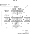
- Fig. 1 is an overview diagram that describes an overall configuration of the carbon dioxide recycling system 1 according to one embodiment.
- this system 1 includes an electrochemical CO 2 reduction device 10, a gas-liquid separation device (a cathode side) 20, a gas separation device (a cathode side) 30, a liquid extraction device (a cathode side) 40, a gas-liquid separation device (an anode side) 50, a gas separation device (an anode side) 60, and a liquid extraction device (an anode side) 70.
- a control device CD such as a computer, controls all of operations by the devices.
- a power supply PS applies a voltage to electrodes (the cathode and the anode) disposed on them.
- This system 1 supplies only an aqueous solution (a CO 2 dissolved aqueous solution) in which CO 2 is dissolved to the electrochemical CO 2 reduction device 10 (that is, does not supply a CO 2 gas at a high concentration), and generates a CO 2 reduction product.
- the CO 2 reduction product includes a carbon compound (C 1 , C 2+ ) with carbon number 1 or 2 or more, that is, an organic compound, such as hydrocarbon.
- the electrochemical CO 2 reduction device 10 will be described later.
- CO 2 recovery liquid neutrality to alkalinity
- a potassium carbonate aqueous solution carbonated water, and seawater
- An example of the CO 2 recovery liquid includes water-soluble amine recovery liquid in which CO 2 is dissolved.
- the above-described CO 2 dissolved aqueous solution, the CO 2 recovery liquid, and the like may be collectively referred to as a carbonate aqueous solution (a CAS).
- C 1 and C 2+ examples include a gas, such as carbon monoxide (CO), methane (CH 4 ), ethane (C 2 H 6 ), ethylene (C 2 H 4 ), and formaldehyde (CH 2 O), and liquid, such as methanol (CH 3 OH), ethanol (C 2 H 5 OH), propanol (C 3 H 7 OH), formic acid (CH 2 O 2 ), and acetaldehyde (CH 3 CHO), but C 1 and C 2+ are not limited thereto.
- a gas such as carbon monoxide (CO), methane (CH 4 ), ethane (C 2 H 6 ), ethylene (C 2 H 4 ), and formaldehyde (CH 2 O)
- liquid such as methanol (CH 3 OH), ethanol (C 2 H 5 OH), propanol (C 3 H 7 OH), formic acid (CH 2 O 2 ), and acetaldehyde (CH 3 CHO), but C 1 and C 2+ are
- CO 2 of the carbonate aqueous solution CAS supplied to the cathode side (a first half cell HC1) (see Fig. 2 ) of the electrochemical CO 2 reduction device 10 is electrolytically reduced by the device 10, and the CO 2 reduction product is generated as described above.
- a point that CO 2 in the carbonate aqueous solution CAS is electrolytically reduced in the first half cell HC1 will be described later.
- gas-liquid separation is performed by the gas-liquid separation device (the cathode side) 20.
- the liquid separated by the gas-liquid separation device (the cathode side) 20 is transmitted to the liquid extraction device (the cathode side) 40, and, for example, extracted for each of chemical species, such as C 2 H 5 OH and C 3 H 7 OH.
- This extraction can be performed by the known method using, for example, a difference in a boiling point.
- the gas separated by the gas-liquid separation device (the cathode side) 20 is transmitted to the gas separation device (the cathode side) 30, and, for example, separated for each of chemical species, such as C 2 H 6 , CH 4 , carbon monoxide (CO), and hydrogen (H 2 ).
- This separation can be performed by the known method using, for example, adsorption and/or desorption actions to a gas separation membrane and an adsorbent.
- the crossover CO 2 , hydrogen peroxide (H 2 O 2 ), and the like are generated on the anode side (the second half cell HC2) (see Fig. 2 ) of the electrochemical CO 2 reduction device 10. They are transmitted to the gas-liquid separation device (the anode side) 50 and gas-liquid separation is performed.
- the liquid (for example, H 2 O 2 ) separated by the gas-liquid separation device (the anode side) 50 is transmitted to the liquid extraction device (the anode side) 70 and separated from water.
- This separation for example, can be performed by distillation or the like but is not limited thereto.
- the gas separated by the gas-liquid separation device (the anode side) 50 is transmitted to the gas separation device (the anode side) 60 and separated into O 2 and crossover CO 2 .
- This separation for example, can be performed by the known method, such as a chemical absorption method, a physical absorption method, a solid absorption method, and membrane separation.
- an electrochemistry pH swing device using the known proton-coupled electron transfer (PCET) organic matter can be used or used in combination.
- PCET proton-coupled electron transfer
- the reuse mechanism 100 that recovers at least one gas among a gas containing unreacted CO 2 discharged from the first half cell HC1 and a gas containing the crossover CO 2 discharged from the second half cell HC2, dissolves the gas in the carbonate aqueous solution CAS and causes the first half cell HC1 to reuse the carbonate aqueous solution CAS as the catholyte is preferably disposed. This allows reusing the unreacted CO 2 and the crossover CO 2 , and therefore the usage efficiency of CO 2 is improved.
- the reuse mechanism 100 electrochemistry pH swing by the proton-coupled electron transfer (PCET) can be used. As described above, using dependence of ionization dissolution of CO 2 on a pH, the reuse mechanism 100 causes only CO 2 to actively transport from the cathode side to the anode side selectively by pH inclination to incrassate the CO 2 . This allows selectively incrassating CO 2 . Additionally, since O 2 or the like that is not ionized to be dissolved is not actively transported, a desorption process of desorbing only CO 2 can be eliminated.
- PCET proton-coupled electron transfer
- Fig. 2 is an overview diagram that describes the electrochemical CO 2 reduction device 10 in the carbon dioxide recycling system 1 according to one embodiment.
- the electrochemical CO 2 reduction device 10 includes a reduction reaction electrode 11 (a cathode), an oxidation reaction electrode 12 (anode), and a first ion exchange membrane 13 disposed between the reduction reaction electrode 11 and the oxidation reaction electrode 12.
- the carbonate aqueous solution CAS in which CO 2 is dissolved is introduced as the catholyte.
- the carbonate aqueous solution CAS similar to the one described above is also introduced as anolyte.
- the electrochemical CO 2 reduction device 10 includes CO 2 gasification means 80 (see Fig. 4 to Fig. 9 ) that gasifies CO 2 in the catholyte immediately before reducing CO 2 in the catholyte in the reduction reaction electrode 11.
- the CO 2 gasification means 80 will be described later.
- a cathode gas diffusion electrode that includes a CO 2 reduction reaction catalyst (a cathode catalyst) in a gas diffusion layer (GDL) with a hydrophobic micro porous layer (MPL) is used.
- MPL for example, one formed by water-repellent resin, such as polytetrafluoroethylene (PTFE) and fluorinated ethylene propylene (FEP), and carbon can be used.
- the cathode catalyst can include a metal material, such as copper (Cu), argentum (Ag), gold (Au), zinc (Zn), lead (Pb), indium (In), tin (Sn), cadmium (Cd), nickel (Ni), iron (Fe), platinum (Pt), and titanium (Ti), metal oxide thereof, and an alloy containing the metals.
- the cathode catalyst is not limited thereto, and as an organometal complex, such as ruthenium (Ru) and rhenium (Re), known as CO 2 reduction catalysts and a carbon material, such as graphene and carbon nanotube, may be used.
- the cathode catalyst can be disposed by application on a surface of the GDL with the MPL or the like. When C 2+ is the object as a CO 2 reduction product as the reduction reaction electrode 11, specifically, a CuO-NPs GDE that supports CuO nanoparticles on the surface of the GDL with the MPL by application can be used.
- an anode GDE that includes an oxygen evolution reaction (OER) catalyst is used.
- OER oxygen evolution reaction
- a metal material such as platinum (Pt), gold (Au), nickel (Ni), cobalt (Co), palladium (Pd), iridium (Ir), manganese (Mn), iron (Fe), ruthenium (Ru), and titanium (Ti), metal oxide thereof, metal hydroxide, an alloy containing the metals, and a porous body formed of a metal complex thereof can be used.
- the oxidation reaction electrode 12 a material known as an oxidation catalyst that can oxidize water (H 2 O) and generate oxygen (O 2 ) and hydrogen peroxide (H 2 O 2 ) can be widely used.
- the oxidation reaction electrode 12 may include a carbon material, such as carbon black, activated carbon, carbon nanotube, graphene, and diamond, transparent conductive oxide, such as indium tin oxide (ITO), zinc oxide (ZnO), and fluorine doped tin oxide (FTO), and further oxide semiconductor (such as TiO 2 , SrTiO 3 , WO 3 , and Fe 2 O 3 ), mixed anion semiconductor (such as oxysulfide Y 2 Ti 2 O 5 S 2 , acid halide Bi 4 NbO 8 Cl, and acid fluoride Pb 2 Ti 2 O 5.4 F 1.2 ).
- ITO indium tin oxide
- ZnO zinc oxide
- FTO fluorine doped tin oxide
- further oxide semiconductor such as TiO 2
- the first ion exchange membrane 13 is, for example, preferably a bipolar membrane (BPM), but, for example, a cation-exchange membrane (CEM), an anion exchange membrane (AEM) can also be used.
- BPM is an ion exchange membrane having a structure of stacking a CEM and an AEM.
- Table 1 and Table 2 show the cathode reaction and the anode reaction when the CEM is used as the first ion exchange membrane 13 (H + moves) and the cathode reaction and the anode reaction when the AEM is used (OH - moves), respectively.
- the BPM is used as the first ion exchange membrane 13
- the stably maintained pH of each electrolyte can be used.
- this system 1 does not receive the supply of the CO 2 gas at the high concentration but receives only the supply of the carbonate aqueous solution CAS to generate the CO 2 reduction product by the electrochemical CO 2 reduction device 10.
- the dissolved CO 2 can be the CO 2 gas near the cathode catalyst of the reduction reaction electrode 11 inside the first half cell HC1 or immediately before the cathode catalyst, a three-phase interface reaction field of CO 2 (gas)-water (liquid)-catalyst (solid) can be formed, and therefore the CO 2 reduction reaction can be achieved.
- Fig. 3 is a graph (Bjerrum plot) showing a relationship between the solubility of CO 2 to water and the pH.
- the horizontal axis indicates the pH and the vertical axis indicates a dissolved inorganic carbon (DIC) rate.
- DIC dissolved inorganic carbon
- the total concentration of the dissolved inorganic carbon changes by the change in pH of the aqueous solution (carbonate equilibrium).
- pKa1 is present in the proximity of pH of 6
- a CO 2 gas (g) increases on the alkaline side (pH of 6 or less)
- vincreases on the neutral side pH of 6 to 9
- PKa2 is present in the proximity of pH of 9, and CO 3 2- increases on the alkaline side (pH of 9 or more).
- the following equilibrated reactions are performed, respectively.
- this system 1 acidifies the carbonate aqueous solution CAS near the cathode catalyst or immediately before the cathode catalyst and supplies the carbonate dissolved in the carbonate aqueous solution CAS to the cathode catalyst as the CO 2 gas.
- the CO 2 reduction reaction can be achieved without ensuring or excessive supply of the CO 2 gas at the high concentration.
- the CO 2 gasification means 80 can be formed by acidifying the carbonate aqueous solution CAS immediately before the introduction of the carbonate aqueous solution CAS in the first half cell HC1 or acidifying the carbonate aqueous solution CAS on the spot near the cathode catalyst.
- the CO 2 gasification means 80 can be formed as follows.
- Fig. 4 is an overview diagram that illustrates one example of an electrochemistry CO 2 gasifier 81 as one aspect of the CO 2 gasification means 80.
- Fig. 4 illustrates the electrochemical CO 2 reduction device 10 and the electrochemistry CO 2 gasifier 81.
- the electrochemistry CO 2 gasifier 81 includes a cathode 82 and an anode 83, a second ion exchange membrane 84 disposed between the cathode 82 and the anode 83, and a power supply 85 connected to the cathode 82 and the anode 83 and applies a voltage to them.
- the electrochemistry CO 2 gasifier 81 includes a third half cell HC3 formed by including the cathode 82 and the second ion exchange membrane 84 and a fourth half cell HC4 formed by including the anode 83 and the second ion exchange membrane 84.
- the second ion exchange membrane 84 is, for example, preferably an AEM.
- the carbonate aqueous solution CAS neutrality to alkalinity
- the electrochemistry CO 2 gasifier 81 supplies H + in the carbonate aqueous solution CAS in the third half cell HC3 to which the voltage is applied by the cathode 82 and acidifies the carbonate aqueous solution CAS to gasify CO 2 .
- the electrochemistry CO 2 gasifier 81 introduces the carbonate aqueous solution CAS containing the gasified CO 2 to the first half cell HC1 of the electrochemical CO 2 reduction device 10 as the catholyte.
- the electrochemistry CO 2 gasifier 81 can stably and reliably introduce the carbonate aqueous solution CAS containing the gasified CO 2 to the first half cell HC1 of the electrochemical CO 2 reduction device 10.
- Fig. 5 is an overview diagram illustrating an electrochemistry CO 2 gasifier 86 according to the first modification as one aspect of the CO 2 gasification means 80.
- Fig. 5 illustrates only the electrochemistry CO 2 gasifier 86.
- the third half cell HC3 includes a first cation exchange membrane 87 between the cathode 82 and the second ion exchange membrane 84. Additionally, the electrochemistry CO 2 gasifier 86 includes a first redox medium RM1 between the cathode 82 and the first cation exchange membrane 87 and the carbonate aqueous solution CAS is introduced between the first cation exchange membrane 87 and the second ion exchange membrane 84.
- the fourth half cell HC4 includes a second cation exchange membrane 88 between the anode 83 and the second ion exchange membrane 84.
- the electrochemistry CO 2 gasifier 86 includes a second redox medium RM2 between the anode 83 and the second cation exchange membrane 88, and the carbonate aqueous solution CAS is introduced between the second cation exchange membrane 88 and the second ion exchange membrane 84.
- the above-described first redox medium RM1 and second redox medium RM2 form a redox pair.
- the redox ions of the first redox medium RM1 and the second redox medium RM2 include K 3 [Fe(CN) 6 ] 3- /K 4 [Fe(CN) 6 ] 4- and IO 3 - /I - , Fe 3+ /Fe 2+ , but the redox ions are not limited thereto.
- the redox ions when K 3 [Fe(CN) 6 ] 3- /K 4 [Fe(CN) 6 ] 4- is used, the following reactions occur in the cathode 82 and the anode 83, respectively.
- the electrochemistry CO 2 gasifier 86 according to the first modification is disposed such that the first redox medium RM1 and the second redox medium RM2 circulate. Thus, concentration polarization of the redox ions by redox reaction of the electrode can be suppressed.
- the second ion exchange membrane 84 uses the BPM. Both of the first cation exchange membrane 87 of the third half cell HC3 and the second cation exchange membrane 88 of the fourth half cell HC4 only need to be the CEM.
- the first cation exchange membrane 87 and the second cation exchange membrane 88 are preferably the same kind but may be different kinds.
- the CEM does not transmit the redox ions but transmits counter ions.
- the CO 2 gas is generated in the catholyte that is acidified by the supply of H + in the third half cell HC3, and it remains in bicarbonate ions or carbonate ions in the anolyte that is alkalized by the supply of OH - in the fourth half cell HC4.
- the catholyte is supplied to the first half cell HC1 of the electrochemical CO 2 reduction device 10, and the anolyte is supplied to the second half cell HC2 of the electrochemical CO 2 reduction device 10.
- the electrochemistry CO 2 gasifier 86 applies a voltage to the cathode 82 and the anode 83 via conducting wires, and performs both generation of H + and OH - in the BPM (the second ion exchange membrane 84) and the redox reaction of redox ions in the anode 83 and the cathode 82 to ensure continuous catholyte acidification on the carbonate aqueous solution CAS and CO 2 gasification.
- Fig. 6 is an overview diagram illustrating an electrochemistry CO 2 gasifier 89 according to the second modification as one aspect of the CO 2 gasification means 80.
- Fig. 6 illustrates only the electrochemistry CO 2 gasifier 89 according to the second modification.
- the electrochemistry CO 2 gasifier 89 according to the second modification differs from the electrochemistry CO 2 gasifier 86 according to the first modification illustrated in Fig. 5 in that a temperature difference is given between the cathode 82 and the anode 83, but the others are similar.
- thermoelectromotive force (the following formula 1)
- an oxidant (Ox) becomes a reductant (Red) on a high temperature side T hot
- Red becomes Ox on a low temperature side T cold
- the electrochemistry CO 2 gasifier 89 includes a heat source (a high temperature side) 82h in the cathode 82 and a heat source (a low temperature side) 83c in the anode 83.
- the temperature difference only needs to occur between the cathode 82 and the anode 83, and only any one of the heat sources may be disposed.
- the heat sources can be without the external power supply, but can be heated and cooled using the external power supply. Without the external power supply, heat and cold generated in an external device can be used.
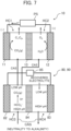
- Fig. 7 is an overview diagram illustrating an electrochemistry CO 2 gasifier 90 according to the third modification as another one aspect of the CO 2 gasification means 80.
- Fig. 7 illustrates the electrochemical CO 2 reduction device 10 and the electrochemistry CO 2 gasifier 90 according to the third modification.
- the third half cell HC3 of the device 90 is connected to the first half cell HC1 and the second half cell HC2 of the electrochemical CO 2 reduction device 10.
- the electrochemistry CO 2 gasifier 90 introduces the carbonate aqueous solution CAS containing CO 2 gasified in the third half cell HC3 to the first half cell HC1 as the catholyte and introduces the carbonate aqueous solution CAS to the second half cell HC2 formed by including the oxidation reaction electrode 12 and the first ion exchange membrane 13 as the anolyte.
- the catholyte introduced to the first half cell HC1 of the electrochemical CO 2 reduction device 10 is acidified in the third half cell HC3 of the electrochemistry CO 2 gasifier 90 according to the third modification, and CO 2 is gasified. Therefore, as described above, the CO 2 reduction product (C 1 , C 2+ ) can be generated by the reduction reaction electrode 11.
- the anolyte introduced to the second half cell HC2 of the electrochemical CO 2 reduction device 10 is acidified in the third half cell HC3 of the electrochemistry CO 2 gasifier 90 according to the third modification, since OH - is supplied in the second half cell HC2, the anolyte becomes neutrality to alkalinity. Therefore, the gasified CO 2 again becomes the carbonate (HCO 3 - , CO 3 2- ) and the carbonate is dissolved in the carbonate aqueous solution CAS.
- the carbonate aqueous solution CAS becomes neutrality to alkalinity, by contact with the CO 2 gas that is unreacted in the first half cell HC1 of the electrochemical CO 2 reduction device 10 separately, the unreacted CO 2 gas can be redissolved in the carbonate aqueous solution CAS.
- the carbonate aqueous solution CAS in which the CO 2 gas unreacted in the first half cell HC1 of the electrochemical CO 2 reduction device 10 is redissolved is referred to as recovered electrolyte in some cases. That is, in this embodiment, since the recovered electrolyte is reused, as the carbonate aqueous solution CAS, the CO 2 reduction product can be generated. Thus, the usage efficiency of CO 2 is improved.
- the recovered electrolyte further can perform supply to the third half cell HC3 again after supply to the fourth half cell HC4 of the electrochemistry CO 2 gasifier 90. Since OH - is supplied to the recovered electrolyte in the fourth half cell HC4, the pH can be high. Accordingly, the CO 2 gas can be dissolved with more certainty.
- Fig. 8 is an overview diagram illustrating an electrochemistry CO 2 gasifier 91 according to the fourth modification as another one aspect of the CO 2 gasification means 80.
- Fig. 8 illustrates only the electrochemistry CO 2 gasifier 91 according to the fourth modification.
- the cathode 82 and the anode 83 are configured as PCET electrodes that perform the proton-coupled electron transfer (PCET) reaction.
- PCET proton-coupled electron transfer
- the following reaction progresses.
- X(s) indicates the PCET electrode.
- the proton H + can be reversibly inserted to and desorbed from the PCET electrode.
- PCET electrode for example, metal oxide, such as MnO 2 , CoO 2 , and NiO 2 , can be used, but the PCET electrode is not limited thereto.
- the method of using the PCET electrode can apply an aqueous solution different from the method of using PCET organic molecules that can be applied to only an aprotic solvent (organic solvent, ionic liquid).
- an aprotic solvent organic solvent, ionic liquid
- the second ion exchange membrane 84 is an AEM.
- the known AEM can be used.
- H + is supplied to the aqueous solution and the pH lowers, and to the PCET electrode that serves as the cathode 82 that is a - pole, H + is supplied from the aqueous solution to the PCET electrode, and the pH becomes high.
- H + reacts to HCO 3 - , and the CO 2 gas is generated.
- the acidified aqueous solution is introduced to the first half cell HC1 of the electrochemical CO 2 reduction device 10 as the catholyte in which CO 2 is gasified.
- the recovered electrolyte at the low pH is introduced to the fourth half cell HC4 of the electrochemistry CO 2 gasifier 91 according to the fourth modification. Since in the recovered electrolyte at the low pH, OH - passes through the AEM to be supplied, and therefore the low pH becomes high. Therefore, the recovered electrolyte can be regenerated as the carbonate aqueous solution CAS obtained by dissolving CO 2 in a state of bicarbonate ions (HCO 3 - ) and carbonate ions (CO 3 2- ).
- Fig. 9 is an overview diagram illustrating an electrochemical CO 2 reduction device 14 according to the other aspect to describe another aspect of the CO 2 gasification means 80.
- the first ion exchange membrane 13 is preferably a BPM.
- H + supplied from the BPM the catholyte is locally acidified at the proximity (on the spot) of the reduction reaction electrode 11, and this gasifies CO 2 in the catholyte.
- the reduction reaction electrode 11 is a GDE with a CO 2 reduction reaction catalyst
- the oxidation reaction electrode 12 is a GDE with an OER catalyst.
- reaction ⁇ 4OH - ⁇ O 2 + 2H 2 O + e -
- reaction ⁇ 4H 2 O ⁇ 4H + + 4OH -
- the catholyte is supplied as the neutral to alkaline carbonate aqueous solution CAS together with anolyte.
- the catholyte is locally acidified by H + supplied from the BPM in the cathode chamber (the first half cell HC1), CO 2 can be reacted to the cathode catalyst as the CO 2 gas. That is, in the aspect, although the carbonate aqueous solution CAS in the state of the carbonate being dissolved in the first half cell HC1 is suppled, the CO 2 gas can be generated near the cathode three-phase interface reaction field, it can be reduced, and the CO 2 reduction product can be generated.
- FIG. 10 is a configuration diagram illustrating one example of a CO 2 reuse mechanism 100.
- the CO 2 reuse mechanism 100 includes a cathode GDE 101, an anode GDE 102, and a quinone solution layer 103 containing a quinone compound as a PCET organic matter and the like between the cathode GDE 101 and the anode GDE 102. That is, the reuse mechanism 100 illustrated in Fig. 10 is an electrochemistry pH swing device using the PCET organic matter.
- the gas introduced to the CO 2 reuse mechanism 100 is one after the gas-liquid separation of the CO 2 reduction product from the electrochemical CO 2 reduction device 10 and one after the gas-liquid separation of the crossover CO 2 , and therefore liquid is absent.
- the gas is a mixed gas containing CO 2 at a comparatively thin concentration in which the unreacted CO 2 , the gas generated in the reaction (such as O 2 ), the crossover CO 2 , or the like is mixed.
- the reuse mechanism 100 introduces the gas from the cathode GDE 101 to the quinone solution layer 103 to perform the PCET reaction, and thus the CO 2 concentration is increased to recover CO 2 from the anode GDE 102. While the CO 2 among the gas introduced from the cathode GDE 101 side is dissolved in the quinone solution layer 103, a gas other than that (for example, N 2 and O 2 ) is not dissolved. Usually, CO 2 is selectively dissolved and afterwards concentrated. The CO 2 recovered from the anode GDE 102 is actively transported selectively by pH inclination and therefore has the high concentration. CO 2 is preferably recovered by sweeping with a gas. Examples of the gas to sweep include an inert gas, such as Ar, and H 2 O.
- the above-described quinone solution layer 103 is preferably a solution obtained by dissolving the quinone compound in an aprotic solvent (an organic solvent and ionic liquid), but is not limited thereto.
- the quinone solution layer 103 may be a separator holding a quinone solution containing 1M or less of a NaHCO 3 aqueous solution.
- the catholyte preferably contains at least one of K + and Na + .
- adsorption of K + and Na + on the surface of the cathode catalyst of the reduction reaction electrode 11 allows suppressing the adsorption of H + . Therefore, hydrogen electrode reaction (HER) advantageous in the acidic environment can be suppressed.
- K + and Na + are preferably one obtained by addition to the catholyte as KCl or NaCl at a concentration of 0.5 to 3 M.
- the HER advantageous in the acidic environment can be suppressed with more certainty.
- the reduction reaction electrode 11 of the electrochemical CO 2 reduction device 10 for example, the use of the cathode GDE including the CO 2 reduction reaction catalyst in the GDL with the MPL has been described, but this embodiment is not limited thereto.
- the use of the anode GDE that includes the OER catalyst as the oxidation reaction electrode 12 of the electrochemical CO 2 reduction device 10 has been described, but this embodiment is not limited thereto.
- the electrode structures of the reduction reaction electrode 11 and the oxidation reaction electrode 12 only need to be a thin film shape, a grid shape, a particle shape, a wire shape, or a porous shape, and can be used not limited to the one described above. Both of the reduction reaction electrode 11 and the oxidation reaction electrode 12 formed by the electrode structures can perform the CO 2 gas reduction reaction and the oxygen evolution reaction from H 2 O described above.
Landscapes
- Chemical & Material Sciences (AREA)
- Organic Chemistry (AREA)
- Engineering & Computer Science (AREA)
- Chemical Kinetics & Catalysis (AREA)
- Electrochemistry (AREA)
- Materials Engineering (AREA)
- Metallurgy (AREA)
- Inorganic Chemistry (AREA)
- Electrolytic Production Of Non-Metals, Compounds, Apparatuses Therefor (AREA)
- Electrodes For Compound Or Non-Metal Manufacture (AREA)
Abstract
Description
- This invention relates to a carbon dioxide recycling system.
- To solve an environmental problem, such as global warming, a reduction in an emission amount of carbon dioxide (CO2) has been demanded. Additionally, expectations to a direct air capture (DAC) technique that artificially recovers CO2 in the atmosphere and further a carbon dioxide capture and utilization (CCU) technique that reduces the recovered CO2 to an effective chemical product for reuse have been increasing.
- To achieve the CO2 recycling and/or circulation system, using water (a proton source) and CO2 (a carbon source) as raw materials, development of an artificial photosynthesis technique that synthesizes fuel and organic matters, such as hydrogen and hydrocarbon, has been advancing. Among the artificial photosynthesis techniques, an electrochemical CO2 reduction device is a device that electrochemically reduces CO2 under ordinary temperature and atmospheric pressure to produce an organic matter, such as a multicarbon compound. When the electrochemical CO2 reduction device operates by renewable energy electric power, such as wind power generation and solar power generation, and the carbon source as the raw material recovered from CO2 in the atmosphere is used, a carbon-negative CO2 recycling device contributing to solution of an environmental problem and an energy problem is configured.
-
Fig. 11 illustrates one example of a conventional electrochemical CO2 reduction device 200 described above. As illustrated inFig. 11 , the electrochemical CO2 reduction device 200 includes acathode chamber 201 as a half cell that reduces CO2 and generates a carbon compound, ananode chamber 202 as a half cell that oxidizes water and generates oxygen, and anion exchange membrane 203 that performs separation into thecathode chamber 201 and theanode chamber 202. In the device, as acathode 204 disposed in thecathode chamber 201, for example, a cathode gas diffusion electrode (GDE) (acathode GDE 204c) that includes a CO2 reduction reaction catalyst (acathode catalyst 204b) in a gas diffusion layer (GDL) with a micro porous layer (MPL) (aGDL 204a with an MPL) is used. As ananode 205 disposed in theanode chamber 202, for example, ananode GDE 205b that includes an oxygen evolution reaction (OER) catalyst (anOER catalyst 205a) is used. As theion exchange membrane 203, an anion-exchange membrane (AEM) is used. For thecathode chamber 201 and theanode chamber 202, as electrolyte, a neutral to alkaline aqueous solution is used. - Here, when catholyte and anolyte are alkaline electrolyte, a CO2 gas is dissolved (consumed) as carbonate. Since the AEM used in the alkaline environment transmits not only OH- but also carbonate (HCO3 -, CO3 2-), crossover occurs from the
cathode 204 side to theanode 205 side, and even when a CO2 gas is excessively supplied to thecathode 204, CO2 usage proportion is considerably low. Therefore, the conventional device excessively supplies a CO2 gas to satisfy a CO2 reduction reaction in an alkaline environment. Even when the catholyte and the anolyte are neutral electrolyte, since H2O becomes a H+ (a proton) source, alkalinization due to local generation of OH- and generation of carbonate in association with it cannot be avoided. - In the device, CO2 as a carbon source of electrolytic reduction is supplied to the
cathode catalyst 204b of thecathode GDE 204c as a CO2 gas. The CO2 reduction reaction in thecathode chamber 201 progresses with a three-phase interface between CO2 (gas), aqueous electrolyte (liquid), and thecathode catalyst 204b (solid) as reaction fields. Therefore, to improve the usage proportion of CO2 and further improve a generation speed of a CO2 reduction product, CO2 needs to be supplied as the gas on a catalyst (solid) surface in the electrolyte (liquid) as described above. As the CO2 reduction product, a carbon compound (C1, C2+) withcarbon number 1 or 2 or more is included. C1,C2+, and unreacted CO2 generated by the electrochemical CO2 reduction device 200 are discharged from thecathode GDE 204c. O2 and the crossover CO2 generated by the electrochemical CO2 reduction device 200 is discharged from theanode GDE 205b. The crossover CO2 means CO2 generated by CO2 supplied to thecathode 204 side passing through theion exchange membrane 203 in the form of carbonate (HCO3 -, CO3 2-) to reach theanode 205 side and directly reacting to H+ locally generated from H2O on theanode 205 side. - The conventional electrochemical CO2 reduction device 200 supplies a CO2 gas at a high concentration to the
cathode chamber 201 of a CO2 reduction cell. To improve the reaction efficiency, as described above, a device, such as application of the gas diffusion electrode (GDE), has been examined. In a place where the CO2 gas at the high concentration cannot be ensured, since the CO2 gas cannot be excessively suppled, the efficiency as the electrochemical CO2 reduction device 200 lowers. - To ensure the CO2 gas at the high concentration described above, a DAC process that recovers dilute CO2 in the atmosphere and concentrates it is required. The current DAC process by a chemical adsorption method using an amine aqueous solution and a physical adsorption method by a porous solid adsorbent requires considerable energy for the concentration of CO2 and considerable energy is taken for a process of desorbing CO2 recovered from the atmosphere as a CO2 gas again, and this becomes one factor of high cost.
- As one example of the conventional electrochemical CO2 reduction device, for example, there is a carbon dioxide reactor described in
JP 2021-147679 A - The carbon dioxide reactor includes an electrochemical reaction cell, a first supply unit, a second supply unit, and a first carbon dioxide separation unit. The above-described electrochemical reaction cell includes a first housing unit, a second housing unit, a diaphragm, a cathode, and an anode. The first housing unit houses first electrolyte containing a gas containing carbon dioxide, or carbon dioxide. The second housing unit houses second electrolyte containing water. The diaphragm is disposed between the first housing unit and the second housing unit. The cathode is disposed so as to be in contact with the gas or the first electrolyte, reduces the carbon dioxide, and generates a carbon compound. The anode is disposed so as to be in contact with the second electrolyte, oxidizes water, and generates oxygen. The first supply unit supplies the first housing unit with the gas or the first electrolyte. The second supply unit supplies the second housing unit with the second electrolyte. The first carbon dioxide separation unit is connected to a discharge unit that discharges an emission containing oxygen and carbon dioxide from the second housing unit and separates the carbon dioxide from the gas component in the emission.
- The conventional electrochemical CO2 reduction device 200 that includes the carbon dioxide reactor described in
JP 2021-147679 A - In the problem, CO2 recycling and/or circulation at low cost is expected by achieving an electrochemical CO2 reduction device (a carbon dioxide recycling system) that does not require the process that recovers and/or concentrates CO2 to obtain the CO2 gas at the high concentration.
- The present invention has been made in consideration of the situation. That is, an object of the present invention is to provide a carbon dioxide recycling system that eliminates a need for a process that recovers and/or concentrates CO2 to obtain a CO2 gas at a high concentration and allows generating a CO2 reduction product.
- A carbon dioxide recycling system in accordance with the present invention for solving the above problems, comprises: an electrochemical CO2 reduction device that includes a reduction reaction electrode, an oxidation reaction electrode, and a first ion exchange membrane disposed between the reduction reaction electrode and the oxidation reaction electrode; and CO2 gasification means that introduces a carbonate aqueous solution in which CO2 is dissolved to a first half cell formed by including the reduction reaction electrode and the first ion exchange membrane as catholyte, and the CO2 gasification means gasifying CO2 in the catholyte immediately before reducing the CO2 in the catholyte in the reduction reaction electrode.
- According to the present invention, it is possible to provide a carbon dioxide recycling system that eliminates a need for a process that recovers and/or concentrates CO2 to obtain a CO2 gas at a high concentration and allows generating a CO2 reduction product. Objects, configurations, and effects other than the above will be apparent from the description of the following embodiments.
-
-
Fig. 1 is an overview diagram that describes an overall configuration of a carbon dioxide recycling system 1 according to one embodiment. -
Fig. 2 is an overview diagram that describes an electrochemical CO2 reduction device 10 in the carbon dioxide recycling system 1 according to one embodiment. -
Fig. 3 is a graph (Bjerrum plot) showing a relationship between solubility of CO2 to water and a pH. -
Fig. 4 is an overview diagram that illustrates one example of an electrochemistry CO2 gasifier 81 as one aspect of CO2 gasification means 80. -
Fig. 5 is an overview diagram illustrating an electrochemistry CO2 gasifier 86 according to a first modification as one aspect of the CO2 gasification means 80. -
Fig. 6 is an overview diagram illustrating an electrochemistry CO2 gasifier 89 according to a second modification as one aspect of the CO2 gasification means 80. -
Fig. 7 is an overview diagram illustrating an electrochemistry CO2 gasifier 90 according to a third modification as another one aspect of the CO2 gasification means 80. -
Fig. 8 is an overview diagram illustrating an electrochemistry CO2 gasifier 91 according to a fourth modification as another one aspect of the CO2 gasification means 80. -
Fig. 9 is an overview diagram illustrating an electrochemical CO2 reduction device 14 according to the other aspect to describe another aspect of the CO2 gasification means 80. -
Fig. 10 is a configuration diagram illustrating one example of a CO2 reuse mechanism 100. -
Fig. 11 is a configuration diagram illustrating one example of a conventional electrochemical CO2 reduction device 200. - The following will describe a carbon dioxide recycling system 1 (hereinafter simply referred to as this system 1 in some cases) according to one embodiment of the present invention in detail with reference to the drawing appropriately.
- In the description of each of embodiments, the identical reference numerals are given to a substantially identical or similar configuration, and when the description overlaps, the description is omitted in some cases.
-
Fig. 1 is an overview diagram that describes an overall configuration of the carbon dioxide recycling system 1 according to one embodiment. - As illustrated in
Fig. 1 , this system 1 includes an electrochemical CO2 reduction device 10, a gas-liquid separation device (a cathode side) 20, a gas separation device (a cathode side) 30, a liquid extraction device (a cathode side) 40, a gas-liquid separation device (an anode side) 50, a gas separation device (an anode side) 60, and a liquid extraction device (an anode side) 70. A control device CD, such as a computer, controls all of operations by the devices. For example, to the electrochemical CO2 reduction device 10, the gas separation device (the cathode side) 30, and the gas separation device (the anode side) 60, a power supply PS applies a voltage to electrodes (the cathode and the anode) disposed on them. - This system 1 supplies only an aqueous solution (a CO2 dissolved aqueous solution) in which CO2 is dissolved to the electrochemical CO2 reduction device 10 (that is, does not supply a CO2 gas at a high concentration), and generates a CO2 reduction product. The CO2 reduction product includes a carbon compound (C1, C2+) with
carbon number 1 or 2 or more, that is, an organic compound, such as hydrocarbon. The electrochemical CO2 reduction device 10 will be described later. - As the aqueous solution, for example, CO2 recovery liquid (neutrality to alkalinity), a potassium carbonate aqueous solution, carbonated water, and seawater can be used. An example of the CO2 recovery liquid includes water-soluble amine recovery liquid in which CO2 is dissolved. In this embodiment, the above-described CO2 dissolved aqueous solution, the CO2 recovery liquid, and the like may be collectively referred to as a carbonate aqueous solution (a CAS).
- Examples of C1 and C2+ include a gas, such as carbon monoxide (CO), methane (CH4), ethane (C2H6), ethylene (C2H4), and formaldehyde (CH2O), and liquid, such as methanol (CH3OH), ethanol (C2H5OH), propanol (C3H7OH), formic acid (CH2O2), and acetaldehyde (CH3CHO), but C1 and C2+ are not limited thereto.
- In this system 1, CO2 of the carbonate aqueous solution CAS supplied to the cathode side (a first half cell HC1) (see
Fig. 2 ) of the electrochemical CO2 reduction device 10 is electrolytically reduced by thedevice 10, and the CO2 reduction product is generated as described above. A point that CO2 in the carbonate aqueous solution CAS is electrolytically reduced in the first half cell HC1 will be described later. - Since the CO2 reduction product generated in the electrochemical CO2 reduction device 10 is a gas or liquid, gas-liquid separation is performed by the gas-liquid separation device (the cathode side) 20. The liquid separated by the gas-liquid separation device (the cathode side) 20 is transmitted to the liquid extraction device (the cathode side) 40, and, for example, extracted for each of chemical species, such as C2H5OH and C3H7OH. This extraction can be performed by the known method using, for example, a difference in a boiling point.
- Meanwhile, the gas separated by the gas-liquid separation device (the cathode side) 20 is transmitted to the gas separation device (the cathode side) 30, and, for example, separated for each of chemical species, such as C2H6, CH4, carbon monoxide (CO), and hydrogen (H2). This separation can be performed by the known method using, for example, adsorption and/or desorption actions to a gas separation membrane and an adsorbent.
- O2, the crossover CO2, hydrogen peroxide (H2O2), and the like are generated on the anode side (the second half cell HC2) (see
Fig. 2 ) of the electrochemical CO2 reduction device 10. They are transmitted to the gas-liquid separation device (the anode side) 50 and gas-liquid separation is performed. The liquid (for example, H2O2) separated by the gas-liquid separation device (the anode side) 50 is transmitted to the liquid extraction device (the anode side) 70 and separated from water. This separation, for example, can be performed by distillation or the like but is not limited thereto. - Meanwhile, the gas separated by the gas-liquid separation device (the anode side) 50 is transmitted to the gas separation device (the anode side) 60 and separated into O2 and crossover CO2. This separation, for example, can be performed by the known method, such as a chemical absorption method, a physical absorption method, a solid absorption method, and membrane separation.
- In the gas separation device (the cathode side) 30 and the gas separation device (the anode side) 60, an electrochemistry pH swing device using the known proton-coupled electron transfer (PCET) organic matter can be used or used in combination. The use of the electrochemistry pH swing device allows recovering only a CO2 gas from a mixed gas component. When only the CO2 gas can be recovered, it is considerably advantageous in reuse of the carbonate aqueous solution CAS.
- That is, in this embodiment, the reuse mechanism 100 (see
Fig. 10 ) that recovers at least one gas among a gas containing unreacted CO2 discharged from the first half cell HC1 and a gas containing the crossover CO2 discharged from the second half cell HC2, dissolves the gas in the carbonate aqueous solution CAS and causes the first half cell HC1 to reuse the carbonate aqueous solution CAS as the catholyte is preferably disposed. This allows reusing the unreacted CO2 and the crossover CO2, and therefore the usage efficiency of CO2 is improved. - As the
reuse mechanism 100, electrochemistry pH swing by the proton-coupled electron transfer (PCET) can be used. As described above, using dependence of ionization dissolution of CO2 on a pH, thereuse mechanism 100 causes only CO2 to actively transport from the cathode side to the anode side selectively by pH inclination to incrassate the CO2. This allows selectively incrassating CO2. Additionally, since O2 or the like that is not ionized to be dissolved is not actively transported, a desorption process of desorbing only CO2 can be eliminated. - Next, the electrochemical CO2 reduction device 10 in this system 1 will be described in detail.
-
Fig. 2 is an overview diagram that describes the electrochemical CO2 reduction device 10 in the carbon dioxide recycling system 1 according to one embodiment. - As illustrated in
Fig. 2 , the electrochemical CO2 reduction device 10 includes a reduction reaction electrode 11 (a cathode), an oxidation reaction electrode 12 (anode), and a firstion exchange membrane 13 disposed between thereduction reaction electrode 11 and theoxidation reaction electrode 12. - In the electrochemical CO2 reduction device 10 in this system 1, to the first half cell HC1 formed by including the
reduction reaction electrode 11 and the firstion exchange membrane 13, the carbonate aqueous solution CAS in which CO2 is dissolved is introduced as the catholyte. - In the electrochemical CO2 reduction device 10, to the second half cell HC2 formed by including the
oxidation reaction electrode 12 and the firstion exchange membrane 13, the carbonate aqueous solution CAS similar to the one described above is also introduced as anolyte. - The electrochemical CO2 reduction device 10 includes CO2 gasification means 80 (see
Fig. 4 to Fig. 9 ) that gasifies CO2 in the catholyte immediately before reducing CO2 in the catholyte in thereduction reaction electrode 11. The CO2 gasification means 80 will be described later. - For the
reduction reaction electrode 11, for example, a cathode gas diffusion electrode (GDE) that includes a CO2 reduction reaction catalyst (a cathode catalyst) in a gas diffusion layer (GDL) with a hydrophobic micro porous layer (MPL) is used. As the MPL, for example, one formed by water-repellent resin, such as polytetrafluoroethylene (PTFE) and fluorinated ethylene propylene (FEP), and carbon can be used. Examples of the cathode catalyst can include a metal material, such as copper (Cu), argentum (Ag), gold (Au), zinc (Zn), lead (Pb), indium (In), tin (Sn), cadmium (Cd), nickel (Ni), iron (Fe), platinum (Pt), and titanium (Ti), metal oxide thereof, and an alloy containing the metals. The cathode catalyst is not limited thereto, and as an organometal complex, such as ruthenium (Ru) and rhenium (Re), known as CO2 reduction catalysts and a carbon material, such as graphene and carbon nanotube, may be used. The cathode catalyst can be disposed by application on a surface of the GDL with the MPL or the like. When C2+ is the object as a CO2 reduction product as thereduction reaction electrode 11, specifically, a CuO-NPs GDE that supports CuO nanoparticles on the surface of the GDL with the MPL by application can be used. - As the
oxidation reaction electrode 12, for example, an anode GDE that includes an oxygen evolution reaction (OER) catalyst is used. As the anode GDE, for example, a metal material, such as platinum (Pt), gold (Au), nickel (Ni), cobalt (Co), palladium (Pd), iridium (Ir), manganese (Mn), iron (Fe), ruthenium (Ru), and titanium (Ti), metal oxide thereof, metal hydroxide, an alloy containing the metals, and a porous body formed of a metal complex thereof can be used. As theoxidation reaction electrode 12, a material known as an oxidation catalyst that can oxidize water (H2O) and generate oxygen (O2) and hydrogen peroxide (H2O2) can be widely used. Examples of theoxidation reaction electrode 12 may include a carbon material, such as carbon black, activated carbon, carbon nanotube, graphene, and diamond, transparent conductive oxide, such as indium tin oxide (ITO), zinc oxide (ZnO), and fluorine doped tin oxide (FTO), and further oxide semiconductor (such as TiO2, SrTiO3, WO3, and Fe2O3), mixed anion semiconductor (such as oxysulfide Y2Ti2O5S2, acid halide Bi4NbO8Cl, and acid fluoride Pb2Ti2O5.4F1.2). As theoxidation reaction electrode 12, in order to increase an electrode reaction area to avoid reaction control of the OER, specifically, IrO2 supported porous Ti felt, Ni foam, Pt mesh, and the like can be used. - The first
ion exchange membrane 13 is, for example, preferably a bipolar membrane (BPM), but, for example, a cation-exchange membrane (CEM), an anion exchange membrane (AEM) can also be used. The BPM is an ion exchange membrane having a structure of stacking a CEM and an AEM. When a voltage (0.83 V) at a theoretical decomposition voltage of water or more is applied to both sides of the BPM, water in the membrane is decomposed to H+ and OH , H+ is supplied to the catholyte, and OH- is supplied to the anolyte. - Here, Table 1 and Table 2 show the cathode reaction and the anode reaction when the CEM is used as the first ion exchange membrane 13 (H+ moves) and the cathode reaction and the anode reaction when the AEM is used (OH- moves), respectively. When the BPM is used as the first
ion exchange membrane 13, even when there is a pH difference between the catholyte and the anolyte, the stably maintained pH of each electrolyte can be used.

- As described above, this system 1 does not receive the supply of the CO2 gas at the high concentration but receives only the supply of the carbonate aqueous solution CAS to generate the CO2 reduction product by the electrochemical CO2 reduction device 10.
- Here, in the electrochemistry CO2 reduction, in a state where CO2 is dissolved, namely, HCO3 - and CO3 2- , the CO2 reduction reaction does not occur in the
reduction reaction electrode 11. - However, as long as the dissolved CO2 can be the CO2 gas near the cathode catalyst of the
reduction reaction electrode 11 inside the first half cell HC1 or immediately before the cathode catalyst, a three-phase interface reaction field of CO2 (gas)-water (liquid)-catalyst (solid) can be formed, and therefore the CO2 reduction reaction can be achieved. - As illustrated in
Fig. 3 , since solubility of CO2 to water depends on a pH, this system 1 uses it.Fig. 3 is a graph (Bjerrum plot) showing a relationship between the solubility of CO2 to water and the pH. In the drawing, the horizontal axis indicates the pH and the vertical axis indicates a dissolved inorganic carbon (DIC) rate. - As illustrated in
Fig. 3 , in the carbonic acid, the total concentration of the dissolved inorganic carbon changes by the change in pH of the aqueous solution (carbonate equilibrium). For example, pKa1 is present in the proximity of pH of 6, a CO2 gas (g) increases on the alkaline side (pH of 6 or less), and vincreases on the neutral side (pH of 6 to 9). PKa2 is present in the proximity of pH of 9, and CO3 2- increases on the alkaline side (pH of 9 or more). In pKa1 and pKa2, the following equilibrated reactions are performed, respectively.
(pKa1) H2CO3 + OH- ⇔ HCO3 - + H2O
(pKa2) HCO3 - + OH- ⇔ CO3 2- + H2O
Regarding H2O, H2O ⇔ H+ + OH- is possibly generated. - As described above, when acidification occurs, CO2 (g) flows out, and when alkalization occurs, CO2 (g) is absorbed to increase the DIC.
DIC = [H2CO3*] + [HCO3 -] + [CO3 2-]
- As illustrated in
Fig. 3 , while CO2 is present as ions (carbonate), such as HCO3 - and CO3 2- , in neutrality to alkalinity, CO2 becomes a CO2 gas in acidity. Therefore, using the property, this system 1 acidifies the carbonate aqueous solution CAS near the cathode catalyst or immediately before the cathode catalyst and supplies the carbonate dissolved in the carbonate aqueous solution CAS to the cathode catalyst as the CO2 gas. - Thus, as one aspect of this system 1, by configuring the electrochemical CO2 reduction device 10 including the CO2 gasification means 80 that acidifies the carbonate aqueous solution CAS, the CO2 reduction reaction can be achieved without ensuring or excessive supply of the CO2 gas at the high concentration.
- The CO2 gasification means 80 can be formed by acidifying the carbonate aqueous solution CAS immediately before the introduction of the carbonate aqueous solution CAS in the first half cell HC1 or acidifying the carbonate aqueous solution CAS on the spot near the cathode catalyst. For example, the CO2 gasification means 80 can be formed as follows.
-
Fig. 4 is an overview diagram that illustrates one example of an electrochemistry CO2 gasifier 81 as one aspect of the CO2 gasification means 80.Fig. 4 illustrates the electrochemical CO2 reduction device 10 and the electrochemistry CO2 gasifier 81. - As illustrated in
Fig. 4 , the electrochemistry CO2 gasifier 81 according to one example includes acathode 82 and ananode 83, a secondion exchange membrane 84 disposed between thecathode 82 and theanode 83, and apower supply 85 connected to thecathode 82 and theanode 83 and applies a voltage to them. - The electrochemistry CO2 gasifier 81 includes a third half cell HC3 formed by including the
cathode 82 and the secondion exchange membrane 84 and a fourth half cell HC4 formed by including theanode 83 and the secondion exchange membrane 84. The secondion exchange membrane 84 is, for example, preferably an AEM. To each of the third half cell HC3 and the fourth half cell HC4, the carbonate aqueous solution CAS (neutrality to alkalinity) is introduced. - The electrochemistry CO2 gasifier 81 supplies H+ in the carbonate aqueous solution CAS in the third half cell HC3 to which the voltage is applied by the
cathode 82 and acidifies the carbonate aqueous solution CAS to gasify CO2. The electrochemistry CO2 gasifier 81 introduces the carbonate aqueous solution CAS containing the gasified CO2 to the first half cell HC1 of the electrochemical CO2 reduction device 10 as the catholyte. - Thus, the electrochemistry CO2 gasifier 81 can stably and reliably introduce the carbonate aqueous solution CAS containing the gasified CO2 to the first half cell HC1 of the electrochemical CO2 reduction device 10.
- In the electrochemistry CO2 gasifier 81, to the carbonate aqueous solution CAS (neutrality to alkalinity) introduced to the third half cell HC3, OH- is supplied by the AEM and OH- is supplied by the
anode 83, and therefore the pH becomes further high. The carbonate aqueous solution CAS with the further high pH is introduced to the second half cell HC2 of the electrochemical CO2 reduction device 10. -
Fig. 5 is an overview diagram illustrating an electrochemistry CO2 gasifier 86 according to the first modification as one aspect of the CO2 gasification means 80.Fig. 5 illustrates only the electrochemistry CO2 gasifier 86. - As illustrated in
Fig. 5 , in the electrochemistry CO2 gasifier 86 according to the first modification, the third half cell HC3 includes a firstcation exchange membrane 87 between thecathode 82 and the secondion exchange membrane 84. Additionally, the electrochemistry CO2 gasifier 86 includes a first redox medium RM1 between thecathode 82 and the firstcation exchange membrane 87 and the carbonate aqueous solution CAS is introduced between the firstcation exchange membrane 87 and the secondion exchange membrane 84. - Furthermore, in the electrochemistry CO2 gasifier 86 according to the first modification, the fourth half cell HC4 includes a second
cation exchange membrane 88 between theanode 83 and the secondion exchange membrane 84. The electrochemistry CO2 gasifier 86 includes a second redox medium RM2 between theanode 83 and the secondcation exchange membrane 88, and the carbonate aqueous solution CAS is introduced between the secondcation exchange membrane 88 and the secondion exchange membrane 84. - The above-described first redox medium RM1 and second redox medium RM2 form a redox pair. Examples of the redox ions of the first redox medium RM1 and the second redox medium RM2 include K3[Fe(CN)6]3-/K4[Fe(CN)6]4- and IO3 -/I- , Fe3+/Fe2+, but the redox ions are not limited thereto. For example, as the redox ions, when K3[Fe(CN)6]3-/K4[Fe(CN)6]4- is used, the following reactions occur in the
cathode 82 and theanode 83, respectively. - Cathode:
[Fe(CN)6]3- + e- → [Fe(CN)6]4
- Anode:
[Fe(CN)6]4- → [Fe(CN)6]3- + e-
- The electrochemistry CO2 gasifier 86 according to the first modification is disposed such that the first redox medium RM1 and the second redox medium RM2 circulate. Thus, concentration polarization of the redox ions by redox reaction of the electrode can be suppressed.
- In the case of the electrochemistry CO2 gasifier 86 according to the first modification, the second
ion exchange membrane 84 uses the BPM. Both of the firstcation exchange membrane 87 of the third half cell HC3 and the secondcation exchange membrane 88 of the fourth half cell HC4 only need to be the CEM. The firstcation exchange membrane 87 and the secondcation exchange membrane 88 are preferably the same kind but may be different kinds. Although the CEM does not transmit the redox ions but transmits counter ions. - In the electrochemistry CO2 gasifier 86 having the configuration illustrated in
Fig. 5 , the CO2 gas is generated in the catholyte that is acidified by the supply of H+ in the third half cell HC3, and it remains in bicarbonate ions or carbonate ions in the anolyte that is alkalized by the supply of OH- in the fourth half cell HC4. The catholyte is supplied to the first half cell HC1 of the electrochemical CO2 reduction device 10, and the anolyte is supplied to the second half cell HC2 of the electrochemical CO2 reduction device 10. - The electrochemistry CO2 gasifier 86 applies a voltage to the
cathode 82 and theanode 83 via conducting wires, and performs both generation of H+ and OH- in the BPM (the second ion exchange membrane 84) and the redox reaction of redox ions in theanode 83 and thecathode 82 to ensure continuous catholyte acidification on the carbonate aqueous solution CAS and CO2 gasification. -
Fig. 6 is an overview diagram illustrating an electrochemistry CO2 gasifier 89 according to the second modification as one aspect of the CO2 gasification means 80.Fig. 6 illustrates only the electrochemistry CO2 gasifier 89 according to the second modification. - As illustrated in
Fig. 6 , the electrochemistry CO2 gasifier 89 according to the second modification differs from the electrochemistry CO2 gasifier 86 according to the first modification illustrated inFig. 5 in that a temperature difference is given between thecathode 82 and theanode 83, but the others are similar. - Therefore, here, the aspect of giving the temperature difference between the
cathode 82 and theanode 83, which is the difference, will be described. - In the aspect, from a principle of a thermochemical battery (temperature difference power generation), by giving the temperature difference between the
cathode 82 and theanode 83, power can be generated by thermoelectromotive force (the following formula 1), and an operation without an external power supply is possible. For example, in an N type redox, an oxidant (Ox) becomes a reductant (Red) on a high temperature side Thot, and Red becomes Ox on a low temperature side Tcold (the following formula 2).
Math. 1
- Ox: OXIDANT
- Red: REDUCTANT
- S: ENTROPY
- F: FARADAY CONSTANT
- The electrochemistry CO2 gasifier 89 according to the second modification illustrated in
Fig. 6 includes a heat source (a high temperature side) 82h in thecathode 82 and a heat source (a low temperature side) 83c in theanode 83. The temperature difference only needs to occur between thecathode 82 and theanode 83, and only any one of the heat sources may be disposed. Additionally, as described above, the heat sources can be without the external power supply, but can be heated and cooled using the external power supply. Without the external power supply, heat and cold generated in an external device can be used. -
Fig. 7 is an overview diagram illustrating an electrochemistry CO2 gasifier 90 according to the third modification as another one aspect of the CO2 gasification means 80.Fig. 7 illustrates the electrochemical CO2 reduction device 10 and the electrochemistry CO2 gasifier 90 according to the third modification. - As illustrated in
Fig. 7 , in the electrochemistry CO2 gasifier 90 according to the third modification, the third half cell HC3 of the device 90 is connected to the first half cell HC1 and the second half cell HC2 of the electrochemical CO2 reduction device 10. - The electrochemistry CO2 gasifier 90 according to the third modification introduces the carbonate aqueous solution CAS containing CO2 gasified in the third half cell HC3 to the first half cell HC1 as the catholyte and introduces the carbonate aqueous solution CAS to the second half cell HC2 formed by including the
oxidation reaction electrode 12 and the firstion exchange membrane 13 as the anolyte. - The catholyte introduced to the first half cell HC1 of the electrochemical CO2 reduction device 10 is acidified in the third half cell HC3 of the electrochemistry CO2 gasifier 90 according to the third modification, and CO2 is gasified. Therefore, as described above, the CO2 reduction product (C1, C2+) can be generated by the
reduction reaction electrode 11. - While the anolyte introduced to the second half cell HC2 of the electrochemical CO2 reduction device 10 is acidified in the third half cell HC3 of the electrochemistry CO2 gasifier 90 according to the third modification, since OH- is supplied in the second half cell HC2, the anolyte becomes neutrality to alkalinity. Therefore, the gasified CO2 again becomes the carbonate (HCO3 -, CO3 2-) and the carbonate is dissolved in the carbonate aqueous solution CAS. Since the carbonate aqueous solution CAS becomes neutrality to alkalinity, by contact with the CO2 gas that is unreacted in the first half cell HC1 of the electrochemical CO2 reduction device 10 separately, the unreacted CO2 gas can be redissolved in the carbonate aqueous solution CAS. In this embodiment, the carbonate aqueous solution CAS in which the CO2 gas unreacted in the first half cell HC1 of the electrochemical CO2 reduction device 10 is redissolved is referred to as recovered electrolyte in some cases. That is, in this embodiment, since the recovered electrolyte is reused, as the carbonate aqueous solution CAS, the CO2 reduction product can be generated. Thus, the usage efficiency of CO2 is improved.
- The recovered electrolyte further can perform supply to the third half cell HC3 again after supply to the fourth half cell HC4 of the electrochemistry CO2 gasifier 90. Since OH- is supplied to the recovered electrolyte in the fourth half cell HC4, the pH can be high. Accordingly, the CO2 gas can be dissolved with more certainty.
-
Fig. 8 is an overview diagram illustrating an electrochemistry CO2 gasifier 91 according to the fourth modification as another one aspect of the CO2 gasification means 80.Fig. 8 illustrates only the electrochemistry CO2 gasifier 91 according to the fourth modification. - As illustrated in
Fig. 8 , in the electrochemistry CO2 gasifier 91 according to the fourth modification, thecathode 82 and theanode 83 are configured as PCET electrodes that perform the proton-coupled electron transfer (PCET) reaction. In thecathode 82 and theanode 83 in the electrochemistry CO2 gasifier 91, the following reaction progresses. In the following formula, X(s) indicates the PCET electrode.
X(s) + nH+ + ne- ⇔ XHn(s)
- That is, in the electrochemistry CO2 gasifier 91, by the electrochemical reaction, the proton H+ can be reversibly inserted to and desorbed from the PCET electrode.
- As the PCET electrode, for example, metal oxide, such as MnO2, CoO2, and NiO2, can be used, but the PCET electrode is not limited thereto.
- The method of using the PCET electrode can apply an aqueous solution different from the method of using PCET organic molecules that can be applied to only an aprotic solvent (organic solvent, ionic liquid).
- In the modification, the second
ion exchange membrane 84 is an AEM. The known AEM can be used. - In the electrochemistry CO2 gasifier 91 according to the fourth modification of the configuration, from the PCET electrode that serves as the
anode 83 that is a + pole by application of a positive electric potential, H+ is supplied to the aqueous solution and the pH lowers, and to the PCET electrode that serves as thecathode 82 that is a - pole, H+ is supplied from the aqueous solution to the PCET electrode, and the pH becomes high. When the pH lowers, H+ reacts to HCO3 -, and the CO2 gas is generated. The acidified aqueous solution is introduced to the first half cell HC1 of the electrochemical CO2 reduction device 10 as the catholyte in which CO2 is gasified. - On the other hand, the recovered electrolyte at the low pH is introduced to the fourth half cell HC4 of the electrochemistry CO2 gasifier 91 according to the fourth modification. Since in the recovered electrolyte at the low pH, OH- passes through the AEM to be supplied, and therefore the low pH becomes high. Therefore, the recovered electrolyte can be regenerated as the carbonate aqueous solution CAS obtained by dissolving CO2 in a state of bicarbonate ions (HCO3 -) and carbonate ions (CO3 2-).
- In the electrochemistry CO2 gasifier 91 according to the fourth modification, periodic electric potential switching (polarity reversion) of the PCET electrode is synchronized with switching of a supply passage of the carbonate aqueous solution CAS (namely, the catholyte) to at least the first half cell HC1. Thus, in this embodiment, the continuous CO2 reduction reaction can be performed.
-
Fig. 9 is an overview diagram illustrating an electrochemical CO2 reduction device 14 according to the other aspect to describe another aspect of the CO2 gasification means 80. - As illustrated in
Fig. 9 , in CO2 gasification means 80Ain the electrochemical CO2 reduction device 14 according to another aspect, the firstion exchange membrane 13 is preferably a BPM. With H+ supplied from the BPM, the catholyte is locally acidified at the proximity (on the spot) of thereduction reaction electrode 11, and this gasifies CO2 in the catholyte. - The
reduction reaction electrode 11 is a GDE with a CO2 reduction reaction catalyst, and theoxidation reaction electrode 12 is a GDE with an OER catalyst. - As examples of a chemical reaction in the electrochemical CO2 reduction device 14 having such a configuration, a reaction α, a reaction β, a reaction γ, and a reaction δ illustrated in
Fig. 9 occur.
(Reaction α) 4OH- → O2 + 2H2O + e-
(Reaction β) 4H2O → 4H+ + 4OH-
(Reaction γ) 2CO3 2- + 4H+ → 2CO2(g) + 2H2O
(Reaction δ) CO2(g) + e- + H2O → CxHyOz + OH-
- In the other aspect, the catholyte is supplied as the neutral to alkaline carbonate aqueous solution CAS together with anolyte. However, as described above, since the catholyte is locally acidified by H+ supplied from the BPM in the cathode chamber (the first half cell HC1), CO2 can be reacted to the cathode catalyst as the CO2 gas. That is, in the aspect, although the carbonate aqueous solution CAS in the state of the carbonate being dissolved in the first half cell HC1 is suppled, the CO2 gas can be generated near the cathode three-phase interface reaction field, it can be reduced, and the CO2 reduction product can be generated.
- One aspect of the reuse mechanism has been described above. Here, another specific aspect of the above-described reuse mechanism will be described.
Fig. 10 is a configuration diagram illustrating one example of a CO2 reuse mechanism 100. - As illustrated in
Fig. 10 , the CO2 reuse mechanism 100 includes acathode GDE 101, ananode GDE 102, and aquinone solution layer 103 containing a quinone compound as a PCET organic matter and the like between thecathode GDE 101 and theanode GDE 102. That is, thereuse mechanism 100 illustrated inFig. 10 is an electrochemistry pH swing device using the PCET organic matter. - The gas introduced to the CO2 reuse mechanism 100 is one after the gas-liquid separation of the CO2 reduction product from the electrochemical CO2 reduction device 10 and one after the gas-liquid separation of the crossover CO2, and therefore liquid is absent. The gas is a mixed gas containing CO2 at a comparatively thin concentration in which the unreacted CO2, the gas generated in the reaction (such as O2), the crossover CO2, or the like is mixed.
- The
reuse mechanism 100 introduces the gas from thecathode GDE 101 to thequinone solution layer 103 to perform the PCET reaction, and thus the CO2 concentration is increased to recover CO2 from theanode GDE 102. While the CO2 among the gas introduced from thecathode GDE 101 side is dissolved in thequinone solution layer 103, a gas other than that (for example, N2 and O2) is not dissolved. Mostly, CO2 is selectively dissolved and afterwards concentrated. The CO2 recovered from theanode GDE 102 is actively transported selectively by pH inclination and therefore has the high concentration. CO2 is preferably recovered by sweeping with a gas. Examples of the gas to sweep include an inert gas, such as Ar, and H2O. The above-describedquinone solution layer 103 is preferably a solution obtained by dissolving the quinone compound in an aprotic solvent (an organic solvent and ionic liquid), but is not limited thereto. For example, thequinone solution layer 103 may be a separator holding a quinone solution containing 1M or less of a NaHCO3 aqueous solution. - In the
cathode GDE 101 and theanode GDE 102 of thereuse mechanism 100, the following reaction progresses. By the reaction, the pH increases on thecathode GDE 101 side and the pH lowers on theanode GDE 102 side of thereuse mechanism 100. In the following formula, Q indicates quinone. Q serves as an oxidant (Ox) and QH2 serves as a reductant (Red).
(Cathode) Q + 2e- +2H+ → QH2
(Anode) QH2 → Q + 2e- +2H+
HCO3 - + H+ → CO2 + H2O
All reactions of theanode GDE 102 is as follows. (All reactions of the anode)
2HCO3 - + QH2 → Q + 2CO2 + 2H2O
- In the carbon dioxide recycling system 1 according to the embodiment, the catholyte preferably contains at least one of K+ and Na+. Thus, adsorption of K+ and Na+ on the surface of the cathode catalyst of the
reduction reaction electrode 11 allows suppressing the adsorption of H+. Therefore, hydrogen electrode reaction (HER) advantageous in the acidic environment can be suppressed. - In the preferred aspect, K+ and Na+ are preferably one obtained by addition to the catholyte as KCl or NaCl at a concentration of 0.5 to 3 M. Thus, the HER advantageous in the acidic environment can be suppressed with more certainty.
- In the above-described embodiment, as the
reduction reaction electrode 11 of the electrochemical CO2 reduction device 10, for example, the use of the cathode GDE including the CO2 reduction reaction catalyst in the GDL with the MPL has been described, but this embodiment is not limited thereto. In the above-described embodiment, for example, the use of the anode GDE that includes the OER catalyst as theoxidation reaction electrode 12 of the electrochemical CO2 reduction device 10 has been described, but this embodiment is not limited thereto. - In this embodiment, the electrode structures of the
reduction reaction electrode 11 and theoxidation reaction electrode 12 only need to be a thin film shape, a grid shape, a particle shape, a wire shape, or a porous shape, and can be used not limited to the one described above. Both of thereduction reaction electrode 11 and theoxidation reaction electrode 12 formed by the electrode structures can perform the CO2 gas reduction reaction and the oxygen evolution reaction from H2O described above. - While the carbon dioxide recycling system 1 according to the present invention has been described in detail by the embodiments, the present invention is not limited to the above-described embodiments but various modifications are included. For example, the embodiments described above have been described in detail to simply describe the present invention, and are not necessarily required to include all the described configurations. In addition, part of the configuration of one embodiment can be replaced with the configurations of other embodiments, and in addition, the configuration of the one embodiment can also be added with the configurations of other embodiments. In addition, part of the configuration of each of the embodiments can be subjected to addition, deletion, and replacement with respect to other configurations.

Claims (15)
- A carbon dioxide recycling system, comprising:an electrochemical CO2 reduction device that includes a reduction reaction electrode, an oxidation reaction electrode, and a first ion exchange membrane disposed between the reduction reaction electrode and the oxidation reaction electrode; andCO2 gasification means that introduces a carbonate aqueous solution in which CO2 is dissolved to a first half cell formed by including the reduction reaction electrode and the first ion exchange membrane as catholyte, and the CO2 gasification means gasifying CO2 in the catholyte immediately before reducing the CO2 in the catholyte in the reduction reaction electrode.
- The carbon dioxide recycling system according to claim 1, whereinthe CO2 gasification means is an electrochemistry CO2 gasifier,the electrochemistry CO2 gasifier includes:a cathode and an anode;a second ion exchange membrane disposed between the cathode and the anode; anda power supply connected to the cathode and the anode and applying a voltage to the cathode and the anode,the carbonate aqueous solution is introduced to each of a third half cell formed by including the cathode and the second ion exchange membrane and a fourth half cell formed by including the anode and the second ion exchange membrane, andin the third half cell to which the voltage is applied, the CO2 in the carbonate aqueous solution is gasified by the cathode, and the carbonate aqueous solution containing the gasified CO2 is introduced to the first half cell as the catholyte.
- The carbon dioxide recycling system according to claim 2, whereinthe third half cell includes a first cation exchange membrane between the cathode and the second ion exchange membrane and includes a first redox medium between the cathode and the first cation exchange membrane, and the carbonate aqueous solution is introduced between the first cation exchange membrane and the second ion exchange membrane,the fourth half cell includes a second cation exchange membrane between the anode and the second ion exchange membrane and includes a second redox medium between the anode and the second cation exchange membrane, and the carbonate aqueous solution is introduced between the second cation exchange membrane and the second ion exchange membrane, andthe first redox medium and the second redox medium are disposed to circulate.
- The carbon dioxide recycling system according to claim 3, wherein
a temperature difference is given between the cathode and the anode. - The carbon dioxide recycling system according to claim 2, whereinthe carbonate aqueous solution containing the gasified CO2 is introduced to the first half cell as the catholyte and is introduced to a second half cell formed by including the oxidation reaction electrode and the first ion exchange membrane as anolyte, anda carbonate aqueous solution introduced to the fourth half cell includes a carbonate aqueous solution containing unreacted CO2 recovered from the first half cell.
- The carbon dioxide recycling system according to claim 2, whereinboth of the cathode and the anode are PCET electrodes that perform a proton-coupled electron transfer reaction,the second ion exchange membrane is an anion exchange membrane, andperiodic electric potential switching to the PCET electrode is synchronized with at least switching of a supply passage of the carbonate aqueous solution to the first half cell.
- The carbon dioxide recycling system according to claim 1, whereinin the CO2 gasification means,the first ion exchange membrane is a bipolar membrane, andthe catholyte is locally acidified at a proximity of the reduction reaction electrode with H+ supplied from the bipolar membrane to gasify the CO2 in the catholyte.
- The carbon dioxide recycling system according to claim 1, comprising:a second half cell formed by including the oxidation reaction electrode and the first ion exchange membrane; anda reuse mechanism that recovers at least one of a gas containing unreacted CO2 discharged from the first half cell and a gas containing crossover CO2 discharged from the second half cell, dissolves the gas in the carbonate aqueous solution, and causes the first half cell to reuse the carbonate aqueous solution as catholyte.
- The carbon dioxide recycling system according to claim 8, wherein
using dependance of ionization dissolution of the CO2 on a pH, the reuse mechanism actively transports only CO2 from a cathode side to an anode side selectively by pH inclination to incrassate the CO2. - The carbon dioxide recycling system according to claim 8, whereinin the reuse mechanism, a quinone solution layer is disposed between the cathode and the anode, andthe gas is introduced from the cathode to the quinone solution, and a proton-coupled electron transfer reaction is performed to increase a CO2 concentration and recover the CO2 from the anode.
- The carbon dioxide recycling system according to claim 1, wherein
the catholyte contains at least one of K+ and Na+. - The carbon dioxide recycling system according to claim 11, wherein
the K+ or the Na+ are added to the catholyte as KCl or NaCl at a concentration of 0.5 to 3 M. - The carbon dioxide recycling system according to claim 1, wherein
the first ion exchange membrane is a cation exchange membrane or an anion exchange membrane. - The carbon dioxide recycling system according to claim 1, wherein
the reduction reaction electrode and the oxidation reaction electrode have an electrode structure of a thin film shape, a grid shape, a particle shape, a wire shape, or a porous shape. - The carbon dioxide recycling system according to claim 1, wherein
the carbonate aqueous solution is water-soluble amine recovery liquid, a potassium carbonate aqueous solution, carbonated water, or seawater, in which CO2 is dissolved.
Applications Claiming Priority (1)
| Application Number | Priority Date | Filing Date | Title |
|---|---|---|---|
| JP2023109620A JP2025007901A (en) | 2023-07-03 | 2023-07-03 | Carbon Dioxide Resource Recovery System |
Publications (2)
| Publication Number | Publication Date |
|---|---|
| EP4488417A2 true EP4488417A2 (en) | 2025-01-08 |
| EP4488417A3 EP4488417A3 (en) | 2026-01-07 |
Family
ID=91530233
Family Applications (1)
| Application Number | Title | Priority Date | Filing Date |
|---|---|---|---|
| EP24181599.2A Pending EP4488417A3 (en) | 2023-07-03 | 2024-06-12 | Carbon dioxide recycling system |
Country Status (2)
| Country | Link |
|---|---|
| EP (1) | EP4488417A3 (en) |
| JP (1) | JP2025007901A (en) |
Citations (1)
| Publication number | Priority date | Publication date | Assignee | Title |
|---|---|---|---|---|
| JP2021147679A (en) | 2020-03-23 | 2021-09-27 | 株式会社東芝 | Carbon dioxide reaction apparatus |
Family Cites Families (5)
| Publication number | Priority date | Publication date | Assignee | Title |
|---|---|---|---|---|
| DE102016220297A1 (en) * | 2016-09-27 | 2018-03-29 | Siemens Aktiengesellschaft | Process and apparatus for the electrochemical utilization of carbon dioxide |
| CA3098176A1 (en) * | 2018-04-25 | 2019-10-31 | The University Of British Columbia | Systems and methods for electrochemical generation of syngas and other useful chemicals |
| CN116669834A (en) * | 2020-11-09 | 2023-08-29 | 加州理工学院 | Electrodialyzer and electrodialysis system for CO2 capture from seawater |
| CN114645290B (en) * | 2022-02-25 | 2023-06-30 | 东南大学 | CO (carbon monoxide) 2 Synchronous conversion system and method for trapping and electric regeneration |
| NL2031327B1 (en) * | 2022-03-18 | 2023-09-29 | Univ Delft Tech | Carbon capture and conversion |
-
2023
- 2023-07-03 JP JP2023109620A patent/JP2025007901A/en active Pending
-
2024
- 2024-06-12 EP EP24181599.2A patent/EP4488417A3/en active Pending
Patent Citations (1)
| Publication number | Priority date | Publication date | Assignee | Title |
|---|---|---|---|---|
| JP2021147679A (en) | 2020-03-23 | 2021-09-27 | 株式会社東芝 | Carbon dioxide reaction apparatus |
Also Published As
| Publication number | Publication date |
|---|---|
| EP4488417A3 (en) | 2026-01-07 |
| JP2025007901A (en) | 2025-01-17 |
Similar Documents
| Publication | Publication Date | Title |
|---|---|---|
| Ren et al. | Water electrolysis for hydrogen production: from hybrid systems to self-powered/catalyzed devices | |
| EP3358042B1 (en) | Electrolysis cell and electrolytic device for carbon dioxide | |
| Gutiérrez-Sánchez et al. | The inhibition of the proton donor ability of bicarbonate promotes the electrochemical conversion of CO2 in bicarbonate solutions | |
| CN107406993B (en) | Filter-Press Photoelectrochemical Water Oxidation and CO2 Reduction Cells | |
| CN105264118B (en) | The electrochemistry formated of ammonia in alkaline medium | |
| US20110079515A1 (en) | Alkaline production using a gas diffusion anode with a hydrostatic pressure | |
| Elgazzar et al. | Electrochemical CO2 reduction to formic acid with high carbon efficiency | |
| JPH07502202A (en) | Electrodialysis tank and electrodialysis method | |
| KR102918183B1 (en) | Catalyst for tungsten oxide and oxygen evolution reactions | |
| KR101451630B1 (en) | Method for reducing carbon dioxide and reductor of carbon dioxide using the same | |
| CN110117794A (en) | A kind of electroreduction CO2The three Room type electrolytic cell devices and its electrolytic method of formates processed | |
| JP2017008341A (en) | Water treatment system utilizing alkaline water electrolyzer and alkaline fuel battery | |
| JP2021531407A5 (en) | ||
| JP2024031641A (en) | Method and apparatus for releasing carbon dioxide dissolved in alkaline liquid, and method and system for recovering carbon dioxide from exhaust gas | |
| Park et al. | Heterostructured nanocatalysts to boost the hydrogen evolution reaction in neutral electrolyte | |
| Kumari et al. | Optimized hydrogen production through donor-assisted saline water splitting and its techno-economic feasibility | |
| WO2024031189A1 (en) | Electro-chemical regeneration system and methods of using same | |
| JP2023125258A (en) | Device for recovering, separating and concentrating carbon dioxide, and method for recovering, separating and concentrating carbon dioxide | |
| CN118996452B (en) | An integrated system for electrolyte recovery, product separation, and CO2 capture in alkaline electrochemical synthesis and its preparation method. | |
| JP2025007901A (en) | Carbon Dioxide Resource Recovery System | |
| JP6991893B2 (en) | Carbon dioxide reduction method and carbon dioxide reduction device | |
| KR102767508B1 (en) | Biogas upgrading apparatus and method thereof | |
| KR102744183B1 (en) | Carbon dioxide conversion system | |
| KR102963700B1 (en) | Carbon Dioxide Conversion Hybrid Power System based on Magnesium-Air Secondary Battery and Seawater Desalination System Thereby | |
| JP7758704B2 (en) | Electrolytic reaction device and electrolytic reaction method |
Legal Events
| Date | Code | Title | Description |
|---|---|---|---|
| PUAI | Public reference made under article 153(3) epc to a published international application that has entered the european phase |
Free format text: ORIGINAL CODE: 0009012 |
|
| STAA | Information on the status of an ep patent application or granted ep patent |
Free format text: STATUS: REQUEST FOR EXAMINATION WAS MADE |
|
| 17P | Request for examination filed |
Effective date: 20240816 |
|
| AK | Designated contracting states |
Kind code of ref document: A2 Designated state(s): AL AT BE BG CH CY CZ DE DK EE ES FI FR GB GR HR HU IE IS IT LI LT LU LV MC ME MK MT NL NO PL PT RO RS SE SI SK SM TR |
|
| RIC1 | Information provided on ipc code assigned before grant |
Ipc: C25B 1/23 20210101AFI20250716BHEP Ipc: C25B 3/26 20210101ALI20250716BHEP Ipc: C25B 9/21 20210101ALI20250716BHEP Ipc: C25B 15/08 20060101ALI20250716BHEP Ipc: C25B 9/23 20210101ALI20250716BHEP Ipc: C25B 1/00 20210101ALI20250716BHEP Ipc: C25B 1/04 20210101ALI20250716BHEP Ipc: C25B 3/25 20210101ALI20250716BHEP Ipc: B01D 61/44 20060101ALI20250716BHEP |
|
| PUAL | Search report despatched |
Free format text: ORIGINAL CODE: 0009013 |
|
| AK | Designated contracting states |
Kind code of ref document: A3 Designated state(s): AL AT BE BG CH CY CZ DE DK EE ES FI FR GB GR HR HU IE IS IT LI LT LU LV MC ME MK MT NL NO PL PT RO RS SE SI SK SM TR |
|
| RIC1 | Information provided on ipc code assigned before grant |
Ipc: C25B 1/23 20210101AFI20251202BHEP Ipc: C25B 3/26 20210101ALI20251202BHEP Ipc: C25B 9/21 20210101ALI20251202BHEP Ipc: C25B 15/08 20060101ALI20251202BHEP Ipc: C25B 9/23 20210101ALI20251202BHEP Ipc: C25B 1/00 20210101ALI20251202BHEP Ipc: C25B 1/04 20210101ALI20251202BHEP Ipc: C25B 3/25 20210101ALI20251202BHEP Ipc: B01D 61/44 20060101ALI20251202BHEP |