EP4488240A2 - Entsalzungssystem und -verfahren - Google Patents
Entsalzungssystem und -verfahren Download PDFInfo
- Publication number
- EP4488240A2 EP4488240A2 EP24214891.4A EP24214891A EP4488240A2 EP 4488240 A2 EP4488240 A2 EP 4488240A2 EP 24214891 A EP24214891 A EP 24214891A EP 4488240 A2 EP4488240 A2 EP 4488240A2
- Authority
- EP
- European Patent Office
- Prior art keywords
- compartment
- valve
- container
- port
- saline
- Prior art date
- Legal status (The legal status is an assumption and is not a legal conclusion. Google has not performed a legal analysis and makes no representation as to the accuracy of the status listed.)
- Pending
Links
Images


Classifications
-
- C—CHEMISTRY; METALLURGY
- C02—TREATMENT OF WATER, WASTE WATER, SEWAGE, OR SLUDGE
- C02F—TREATMENT OF WATER, WASTE WATER, SEWAGE, OR SLUDGE
- C02F1/00—Treatment of water, waste water, or sewage
- C02F1/44—Treatment of water, waste water, or sewage by dialysis, osmosis or reverse osmosis
- C02F1/441—Treatment of water, waste water, or sewage by dialysis, osmosis or reverse osmosis by reverse osmosis
-
- B—PERFORMING OPERATIONS; TRANSPORTING
- B01—PHYSICAL OR CHEMICAL PROCESSES OR APPARATUS IN GENERAL
- B01D—SEPARATION
- B01D61/00—Processes of separation using semi-permeable membranes, e.g. dialysis, osmosis or ultrafiltration; Apparatus, accessories or auxiliary operations specially adapted therefor
- B01D61/02—Reverse osmosis; Hyperfiltration ; Nanofiltration
- B01D61/025—Reverse osmosis; Hyperfiltration
-
- B—PERFORMING OPERATIONS; TRANSPORTING
- B01—PHYSICAL OR CHEMICAL PROCESSES OR APPARATUS IN GENERAL
- B01D—SEPARATION
- B01D61/00—Processes of separation using semi-permeable membranes, e.g. dialysis, osmosis or ultrafiltration; Apparatus, accessories or auxiliary operations specially adapted therefor
- B01D61/02—Reverse osmosis; Hyperfiltration ; Nanofiltration
- B01D61/08—Apparatus therefor
-
- B—PERFORMING OPERATIONS; TRANSPORTING
- B01—PHYSICAL OR CHEMICAL PROCESSES OR APPARATUS IN GENERAL
- B01D—SEPARATION
- B01D61/00—Processes of separation using semi-permeable membranes, e.g. dialysis, osmosis or ultrafiltration; Apparatus, accessories or auxiliary operations specially adapted therefor
- B01D61/02—Reverse osmosis; Hyperfiltration ; Nanofiltration
- B01D61/12—Controlling or regulating
-
- B—PERFORMING OPERATIONS; TRANSPORTING
- B01—PHYSICAL OR CHEMICAL PROCESSES OR APPARATUS IN GENERAL
- B01D—SEPARATION
- B01D63/00—Apparatus in general for separation processes using semi-permeable membranes
- B01D63/10—Spiral-wound membrane modules
-
- B—PERFORMING OPERATIONS; TRANSPORTING
- B01—PHYSICAL OR CHEMICAL PROCESSES OR APPARATUS IN GENERAL
- B01D—SEPARATION
- B01D65/00—Accessories or auxiliary operations, in general, for separation processes or apparatus using semi-permeable membranes
- B01D65/02—Membrane cleaning or sterilisation ; Membrane regeneration
-
- C—CHEMISTRY; METALLURGY
- C02—TREATMENT OF WATER, WASTE WATER, SEWAGE, OR SLUDGE
- C02F—TREATMENT OF WATER, WASTE WATER, SEWAGE, OR SLUDGE
- C02F1/00—Treatment of water, waste water, or sewage
- C02F1/008—Control or steering systems not provided for elsewhere in subclass C02F
-
- B—PERFORMING OPERATIONS; TRANSPORTING
- B01—PHYSICAL OR CHEMICAL PROCESSES OR APPARATUS IN GENERAL
- B01D—SEPARATION
- B01D2313/00—Details relating to membrane modules or apparatus
- B01D2313/24—Specific pressurizing or depressurizing means
- B01D2313/243—Pumps
-
- B—PERFORMING OPERATIONS; TRANSPORTING
- B01—PHYSICAL OR CHEMICAL PROCESSES OR APPARATUS IN GENERAL
- B01D—SEPARATION
- B01D2315/00—Details relating to the membrane module operation
- B01D2315/10—Cross-flow filtration
-
- B—PERFORMING OPERATIONS; TRANSPORTING
- B01—PHYSICAL OR CHEMICAL PROCESSES OR APPARATUS IN GENERAL
- B01D—SEPARATION
- B01D2321/00—Details relating to membrane cleaning, regeneration, sterilization or to the prevention of fouling
- B01D2321/04—Backflushing
-
- C—CHEMISTRY; METALLURGY
- C02—TREATMENT OF WATER, WASTE WATER, SEWAGE, OR SLUDGE
- C02F—TREATMENT OF WATER, WASTE WATER, SEWAGE, OR SLUDGE
- C02F2103/00—Nature of the water, waste water, sewage or sludge to be treated
- C02F2103/08—Seawater, e.g. for desalination
-
- C—CHEMISTRY; METALLURGY
- C02—TREATMENT OF WATER, WASTE WATER, SEWAGE, OR SLUDGE
- C02F—TREATMENT OF WATER, WASTE WATER, SEWAGE, OR SLUDGE
- C02F2201/00—Apparatus for treatment of water, waste water or sewage
- C02F2201/002—Construction details of the apparatus
- C02F2201/005—Valves
-
- C—CHEMISTRY; METALLURGY
- C02—TREATMENT OF WATER, WASTE WATER, SEWAGE, OR SLUDGE
- C02F—TREATMENT OF WATER, WASTE WATER, SEWAGE, OR SLUDGE
- C02F2209/00—Controlling or monitoring parameters in water treatment
- C02F2209/03—Pressure
-
- C—CHEMISTRY; METALLURGY
- C02—TREATMENT OF WATER, WASTE WATER, SEWAGE, OR SLUDGE
- C02F—TREATMENT OF WATER, WASTE WATER, SEWAGE, OR SLUDGE
- C02F2209/00—Controlling or monitoring parameters in water treatment
- C02F2209/05—Conductivity or salinity
-
- C—CHEMISTRY; METALLURGY
- C02—TREATMENT OF WATER, WASTE WATER, SEWAGE, OR SLUDGE
- C02F—TREATMENT OF WATER, WASTE WATER, SEWAGE, OR SLUDGE
- C02F2209/00—Controlling or monitoring parameters in water treatment
- C02F2209/40—Liquid flow rate
-
- C—CHEMISTRY; METALLURGY
- C02—TREATMENT OF WATER, WASTE WATER, SEWAGE, OR SLUDGE
- C02F—TREATMENT OF WATER, WASTE WATER, SEWAGE, OR SLUDGE
- C02F2301/00—General aspects of water treatment
- C02F2301/04—Flow arrangements
- C02F2301/043—Treatment of partial or bypass streams
-
- C—CHEMISTRY; METALLURGY
- C02—TREATMENT OF WATER, WASTE WATER, SEWAGE, OR SLUDGE
- C02F—TREATMENT OF WATER, WASTE WATER, SEWAGE, OR SLUDGE
- C02F2301/00—General aspects of water treatment
- C02F2301/04—Flow arrangements
- C02F2301/046—Recirculation with an external loop
-
- C—CHEMISTRY; METALLURGY
- C02—TREATMENT OF WATER, WASTE WATER, SEWAGE, OR SLUDGE
- C02F—TREATMENT OF WATER, WASTE WATER, SEWAGE, OR SLUDGE
- C02F2303/00—Specific treatment goals
- C02F2303/16—Regeneration of sorbents, filters
-
- Y—GENERAL TAGGING OF NEW TECHNOLOGICAL DEVELOPMENTS; GENERAL TAGGING OF CROSS-SECTIONAL TECHNOLOGIES SPANNING OVER SEVERAL SECTIONS OF THE IPC; TECHNICAL SUBJECTS COVERED BY FORMER USPC CROSS-REFERENCE ART COLLECTIONS [XRACs] AND DIGESTS
- Y02—TECHNOLOGIES OR APPLICATIONS FOR MITIGATION OR ADAPTATION AGAINST CLIMATE CHANGE
- Y02A—TECHNOLOGIES FOR ADAPTATION TO CLIMATE CHANGE
- Y02A20/00—Water conservation; Efficient water supply; Efficient water use
- Y02A20/124—Water desalination
- Y02A20/131—Reverse-osmosis
Definitions
- the invention relates to a desalination system and a method of operating a desalination system.
- Desalination systems have many industrial applications.
- One application is the separation of potable water from groundwater that is saline and therefore unfit for drinking.
- Other applications include the treatment of seawater and of saline effluents produced by textile factories.
- WO 2020/039158 A1 discloses a system and method for batch reverse osmosis that is capable of achieving a high recovery ratio (defined as the volume ratio between clean water output and feed water input), requiring only two pumps and three valves, which avoids the complexity of some earlier designs.
- a problem is that the recovery ratio of a batch reverse osmosis system depends on the size of the vessels in the system, with a higher recovery ratio requiring a larger pressure vessel. As the recovery ratio approaches unity the vessel becomes unrealistically large, putting a limit on practical implementations.
- Different techniques such as semi-batch reverse osmosis can avoid the need for larger pressure vessels but have a disadvantage of a larger energy requirement as the recovery ratio is increased. It would therefore be advantageous to provide a system and method that is capable of a high recovery ratio with low energy consumption along with a compact size.
- a desalination system comprising:
- An advantage of the desalination system is that the arrangement of vessels and valves allows for the system to be operated in both semi-batch and batch mode, resulting in a hybrid mode that combines the advantages of both by enabling a high recovery rate with a low energy consumption and a compact size.
- the desalination system may further comprise an inlet valve connected between the feed pump outlet and the first inlet port.
- the system can, however, work without an inlet valve because in practice, whenever the bypass valve is open, fluid from the feed pump will tend to flow preferentially through the bypass valve rather than through the first inlet port into the partitioned container, providing the bypass valve and the first inlet port of the partitioned container are proportioned appropriately.
- An advantage of not having the inlet valve is that fewer moving parts are required in the system, while an advantage of the inlet valve being present is having more control over operation of the desalination system.
- the desalination system may comprise a controller connected and configured to operate the desalination system, the controller configured to:
- the controller may be configured and connected to control operation of one or more, and optionally all, of the main valve, purge valve, inlet valve, if present, and bypass valve.
- the inlet valve if present, may be configured to open when a pressure between the feed pump and the inlet valve rises above a threshold pressure level.
- the bypass valve may be configured to close when a pressure between the feed pump and the bypass valve rises above the threshold pressure level.
- the controller may be configured to open the inlet valve, if present, and close the bypass valve to end the first pressurisation stage and begin the second pressurisation stage.
- the end of the first pressurisation stage and the start of the second pressurisation stage may be determined in a number of ways.
- the desalination system comprises a pressure sensor arranged to measure pressure of saline water provided by the feed pump, the controller being configured to open the inlet valve, if present, and close the bypass valve when a pressure between the feed pump and the inlet valve, or between the feed pump and the first inlet port, rises above a threshold pressure level.
- the desalination system comprises a conductivity sensor arranged to measure electrical conductivity of saline water passing through the recirculation pump, the controller being configured to open the inlet valve, if present, and close the bypass valve when a conductivity of saline water flowing through the recirculation pump rises above a threshold conductivity level.
- the controller is configured to open the inlet valve, if present, and close the bypass valve when a threshold volume of saline water has been provided by the feed pump in the first pressurisation stage. This may be determined by measuring flow of saline water, for example knowing the pumping rate of the feed pump. With a known pumping rate, the threshold volume may be determined by a time threshold.
- a desalination system comprising:
- the desalination system may comprise an inlet valve connected between the feed pump outlet and the first inlet port.
- the inlet valve is closed in the first pressurisation stage and open in the second pressurisation stage and the recharge stage.
- the first and second pressurisation stages and the recharge stage may be repeated in sequence.
- the first pressurisation stage may end and the second pressurisation stage begin when a pressure in saline water fed by the feed pump rises to a threshold pressure level.
- the first pressurisation stage may end and the second pressurisation stage begin when an electrical conductivity of saline water passing through the recirculation pump rises to a conductivity threshold level.
- the first pressurisation stage may end and the second pressurisation stage begin when a threshold volume of saline water provided by the feed pump during the first pressurisation stage is reached.
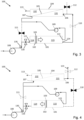
- the desalination system illustrated in figure 1 comprises a first partitioned container 101 and a second membrane container 104.
- the partitioned container 101 is divided by a mobile partition or piston 102 into an upstream compartment 114 and a downstream compartment 115.
- a supply of pressurised saline water is provided by a feed pump 108 and a feed of desalinated water is provided at an outlet port 113.
- a semipermeable membrane 105 divides the membrane container 104 into a saline compartment 131 and a desalinated compartment 132.
- the partitioned container 101 may be a cylindrical vessel housing a piston 102, where the piston 102 is slidably mounted within the cylindrical vessel 101.
- the vessel 101 may be made from a glass-reinforced plastic, stainless steel or some other material resistant to pressure and to corrosion by saline water.
- the internal diameter of the vessel 101 may typically be four inches (approximately 10.2 cm).
- the piston 102 may be machined to a diameter just less than four inches, enabling it to slide freely inside the cylindrical vessel 101.
- the piston may be fitted with an O-ring seal 103.
- the piston 102 may be machined to a sufficiently close tolerance to prevent significant leakage, and therefore without need for any seal.
- the vessel 104 containing the membrane 105 may be in the form of a second cylindrical vessel housing a semipermeable membrane element 105 of a type that allows a cross flow to occur, as it is important to sweep concentrated saline solution from the surface of the membrane 105.
- First and second cross-flow ports 106 and 107 allow the cross flow to respectively enter and leave the vessel 104 in both directions, i.e. flowing in through the second cross-flow port 107 and out through the first cross-flow port 106, and vice versa.
- the membrane element 105 used may be of a spiral-wound reverse osmosis type, such as is commonly used in the desalination industry. Hollow-fibre or flat-sheet reverse osmosis membranes may also be used.
- the system 100 comprises a first high-pressure feed pump 108 and a second low-pressure recharge or recirculation pump 109.
- the feed pump 108 provides a supply of saline water to a first inlet 121 of the cylindrical vessel 101 via an inlet valve 116 and/or to a recharge or recirculation circuit via a bypass valve 111.
- the inlet valve 116 may be omitted without affecting operation of the system 100.
- the bypass valve 111 is connected between the outlet 129 of the feed pump 108 and the second cross-flow port 107 and allows, when opened, saline water from the feed pump 108 to bypass the cylindrical vessel 101 and flow into the a recirculation loop comprising the saline compartment 131 of the membrane container 104 and the recirculation pump 109.
- a purge valve 112 connected between the first cross-flow port 106 and a purge outlet 123 allows, when opened, concentrated saline water from the saline compartment 131 of the membrane container 104 to flow from the first cross-flow port 106 to the purge outlet 123.
- Valves 110, 111, 112, 116 may be solenoid valves.
- the main valve 110 and inlet valve 116 may be of normally-open type, whereas the bypass valve 111 and purge valve 112 may be of normally-closed type.
- valves 110, 111, 112 may be motorised or pneumatically actuated or may in some cases, in particular for the bypass, main and inlet valves 111, 110, 116 be pressure actuated, as for example disclosed in WO 2020/039158 A1 .
- An electrical control unit or controller 125 is connected and configured to operate the valves 110, 111, 112, 116, which may be done in response to sensors 126, 127 arranged to detect the position of the piston 102.
- a first sensor 126 may be provided at the first inlet 121 to detect when the piston 102 has moved back to the starting position, i.e. the upstream end towards the first inlet 121 end of the vessel 101.
- a second sensor 127 may be provided at the second inlet 122 to detect when the piston 102 has moved to the downstream end of the vessel 101.
- the sensors 126, 127 may be pressure or flow sensors.
- a pressure rise in the upstream or downstream compartments 114, 115 will result when the piston 102 reaches either end of the vessel 101, which can be detected by the relevant sensor 126, 127.
- a pressure difference between sensors 127, 126 positioned at or near the outlet 124 and inlet 121 respectively may be used to detect when the piston 102 has reached either end of the vessel 101.
- a reduction in flow rate will result when the piston 102 reaches either end of the vessel 101.
- the first sensor 126 may for example be a pressure sensor, as the pressure available from the first pump 108 is larger.
- the second sensor 127 may be a flow sensor, since the pressure variation will be less when the piston 102 has returned to the upstream end of the vessel 101.
- the sensors 126, 127 may be proximity sensors, configured to provide a signal when the piston 102 is in proximity of the sensor, thereby detecting when the piston 102 is at the upstream or downstream end of the partitioned container 101.
- a further pressure sensor 130 positioned between the feed pump outlet 129 and the inlet valve 116 may be provided to sense the pressure of the liquid being provided to the system 100 via the feed pump 108. This pressure can be used to trigger operation of the system to switch from a first to a second stage, as described in more detail below.
- a conductivity sensor 133 may alternatively or additionally be provided, the output from which could be used to detect the concentration of salt within the recirculation loop and trigger the system to switch from the first to second stages, as described in further detail below.
- the conductivity sensor 133 may be positioned on either side of the recirculation pump 109 or the main valve 110 in order to measure the electrical conductivity of saline water passing through the recirculation pump 109.
- the various components of the desalination system 100 may be connected by pressure- and corrosion-resistant pipes, as indicated by solid lines in Figure 1 .
- These pipes are typically constructed of polyvinyl chloride or of stainless steel and connected by screw threads or flanges using techniques that will be well known to those skilled in the art of designing and constructing desalination system.
- Saline feed water enters the system at the inlet 128 of the feed pump 108 and is separated into desalinated water that leaves via the outlet or permeate port 113, while concentrated saline water leaves via the purge valve 112 and purge port 123.
- the method of operation by which this separation is achieved comprises three stages comprising first and second pressurisation stages followed by a purge-refill stage, as explained below with reference to Figures 2 , 3 and 4 respectively.
- pipes carrying a flow of water are indicated by solid lines while those carrying no flow are indicated by broken lines.
- Flow is switched on and off by valves 110, 111, 112 and 116, whether by pressure activation or under control of the controller 125. Closed positions of the valves 110, 111, 112 are indicated by solid shading, whereas open positions are indicated by valves drawn in outline without shading.
- the inlet valve 116 and purge valve 112 are closed while the main valve 110 and bypass valve 111 are open.
- the inlet valve 116 may be omitted because flow provided by the feed pump 108 will tend to preferentially flow through the bypass valve 111 without the inlet valve 116 being provided.
- the feed pump 108 and recirculation pump 109 are operated, the feed pump 108 providing a supply of saline water to a recirculation circuit comprising the saline compartment 131 of the membrane container 104 and pipes connecting the second cross-flow port 107 to the first cross-flow port 106 via the recirculation pump 109 and the main valve 110.
- the recirculation circuit also includes a portion of the downstream compartment 115 of the container 101 as flow passes into the compartment 115 through the second inlet port 122 and out of the compartment 115 through the outlet 124. Because the inlet valve 116 is closed, or because flow from the feed pump 108 flows preferentially through the bypass valve 111, the piston 102 is stationary during the first stage and the amount of salt within the recirculation loop gradually increases as the pressure increases. Desalinated water is output during the first stage via the permeate outlet port 113.
- a threshold which may be once the saline water pressure, as measured by pressure sensor 130, has risen to a threshold level, once the concentration of salt within the recirculation loop has reached a threshold level as measured by the sensor 133, or once a predetermined volume of saline water has been pumped into the system by the feed pump 108, as determined by a volume or time measurement, the system switches from the first stage to a second stage, as illustrated in Figure 3 . In this stage, the bypass valve 111 and purge valve 112 are closed while the inlet valve 116 (if present) and main valve 110 are open. The feed pump 108 and recirculation pump 109 continue operation.
- the transition from the first stage to the second stage is therefore effected by closing the bypass valve and opening the inlet valve 116 (if present). This may be done by actuating the valves 111, 116 using the controller 125 (see Figure 1 ) or by actuating the bypass valve 111 alone if the inlet valve 116 is not present.
- the end of the second stage is reached once the piston 102 has reached the end of the partitioned container 101, i.e. when the upstream compartment 114 is maximised and the downstream compartment 115 is minimised.
- the third stage begins, which is shown in Figure 4 .
- the inlet valve 116 if present
- bypass valve 111 and purge valve 112 are open, while the main valve 110 is closed. Transitioning from the second stage to the third stage therefore involves opening the bypass valve 111, opening the purge valve 112 and closing the main valve 110.
- the feed pump 108 and recirculation pump 109 continue operation.
- Saline water from the feed pump 108 is fed via the bypass valve 111 into the saline compartment 131 of the membrane container 104, flushing concentrated saline water out of the first cross-flow port 106 and out through the purge port via the purge valve 112.
- the recirculation pump 109 feeds saline water into the downstream compartment 115 of the partitioned container 101, causing the volume of the upstream compartment 114 to reduce as the downstream compartment 115 fills with saline water.
- Figure 5 illustrates in schematic form an example method of operation for a desalination system of the types described above.
- a first step 501 the inlet valve 116 (if present) and purge valves 112 are closed and the bypass valve 111 and main valve 110 are open.
- the feed pump 108 and recirculation pump 109 are operated to supply saline water to the recirculation circuit.
- desalinated water is output from the permeate port 113.
- a check is made to determine whether a pressure, salt concentration, volume of saline water or time threshold has been reached. In one example, the pressure is monitored (for example by measuring pressure with pressure sensor 130) and checked against a pressure threshold value.
- the salinity of water within the recirculation loop is measured by the conductivity sensor 133 and checked against a conductivity threshold.
- a volume of water provided by the feed pump may be checked against a volume threshold or a time threshold may be checked. This repeats until the threshold is reached, at which point the method proceeds to step 504 where the bypass valve 111 is closed and the inlet valve 116 (if present) is opened.
- the feed pump 108 and recirculation pump 109 then continue to operate (step 505) and a check is made at step 506 on the position of the piston 102 within the partitioned container 101.
- step 507 the purge valve 112 is opened, the main valve 110 is closed and the bypass valve 111 is opened.
- the feed pump 108 and recirculation pump 109 continue to operate (step 508).
- a check is made (step 509) to determine when the piston 102 has reached the upstream end of the partitioned container 101, i.e. when the upstream compartment 114 is minimised and the downstream compartment is maximised. Once this happens, the process then repeats by proceeding back to step 501.
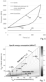
- Figure 6 illustrates pressure as a function of time for different types of desalination processes.
- a minimum pressure 601 of around 250 kPa is required to cause desalinated water to cross the membrane.
- the pressure 602 rises from just over 500 kPa to around 800 kPa after around 300 seconds, at which point the process ends.
- the pressure 603 rises roughly linearly from the same starting point to around 3100 kPa.
- the pressure 604 initially rises in a similar way to the batch process 602 because saline water is fed directly through to the saline compartment 131 of the membrane container 104.
- the pressure may be slightly higher than that for the semi-batch process during this stage, but the difference is not significant in terms of the overall energy consumption.
- An advantage of the process and system described herein is that the total energy used per cycle is lower.
- the energy used is related to the area under each pressure curve in Figure 6 .
- the area under pressure curve 604 is clearly substantially smaller than that under pressure curve 603.
- the vessel size for an equivalent efficiency may be more than halved using a system of the type described herein as compared to a system of the type described in WO 2020/039158 A1 , for example reducing a vessel from around 135 litres to around 60 litres with a similar specific energy of around 0.38 kWh/m 3 with feedwater having 3g of salt per litre at 25°C and a 90% recovery rate.
- the contour plot in Figure 7 illustrates batch volume V b0 for the hybrid system described herein against that for a conventional batch reverse osmosis (RO) system.
- the horizontal axis shows the vessel size in the batch RO system described in WO 2020/039158 A1 and the vertical axis that in the hybrid system of the type described herein.
- Designs of batch system lie on the diagonal line 701, this giving the largest vessel size.
- Designs of an example semi-batch system, based on US498330 lie on the horizontal axis such that the vessel size is zero.
- the hybrid designs are those in the lower triangle bounded by those two extremes, with specific energy consumption represented by the contours.
- the contours show that a substantial reduction in vessel size causes only a small penalty in energy consumption. For example, at 95% recovery, reducing the vessel size from 275.7 litres to 97.1 litres will result in a specific energy consumption (SEC) increase of only 0.0107 kWh/m 3 from the batch RO system (0.2079 kWh/m 3 ). Although the vessel size is three times smaller, the energy penalty of the hybrid process is very small (less than 5%).
- the SEC of the hybrid system is 0.2184 kWh/m 3 , which is substantially low compared to 0.6921 kWh/m 3 for the semi-batch system.
- An example desalination system 100 was constructed with a partitioned container 101 having an internal diameter of 24 cm, the partitioned container housing a piston 102 providing a swept length of 155 cm, giving a displaced volume of 70 litres.
- a membrane container 104 was provided with an internal diameter of 20 cm and internal length of 1 m, housing a semipermeable membrane 105 with a surface area of 40 m 2 .
- Other components of the system were provided as in the embodiments described herein, with a concentration sensor 133 being provided in the recirculation loop.
- the example desalination system 100 was used to desalinate saline water containing sodium chloride with a concentration of 0.85 g/l.
- the feed pump 108 was operated to supply water to the system at a flow rate of 12 litres per minute.
- the recirculation flow provided by the recirculation pump 109 was set to a substantially larger flow of 42 litres per minute.
- the purge valve 112 and inlet valve 116 were closed while the main valve 110 and bypass valve 111 were open. Permeate flowed out of the system at a rate of 12 litres per minute.
- the concentration of salt in the recirculation loop of the system gradually increased, causing the pressure in the system to increase accordingly.
- the controller 125 monitored this concentration with the conductivity sensor 133 and detected when it exceeded a threshold level of 4 g/l.
- the controller 125 then switched the system to the second pressurisation stage (i.e. batch mode) by closing the bypass valve 111 and opening the inlet valve 116. This caused the piston 102 to move in the direction of the downstream compartment 115, while permeate continued to exit at 12 litres per minute.
- the recirculation loop concentration then increased more rapidly, until the piston 102 reached the end of its stroke, at which point the controller 125 opened the purge valve 112 and bypass valve 111, and closed the main valve 110 (while the inlet valve 116 remained open) thus starting the recharge stage.
- Brine was collected during the recharge stage and its salinity was measured as 15.1 g/l, which was 17.8 times more concentrated than the feed water salinity. In total, 363 litres of permeate was collected during the test, compared to 379 litres of feed water supplied. This corresponded to a recovery of 96%.
- the hydraulic work needed to power the system was also measured as the total work of the two pumps 108, 109, according to the displaced volume and average pressure supplied by each pump. The specific energy consumption of the system 100 was thus determined to be 0.5 kWh per cubic metre of permeate output.
- the invention may relate to one or more of the following aspects.
Landscapes
- Chemical & Material Sciences (AREA)
- Engineering & Computer Science (AREA)
- Water Supply & Treatment (AREA)
- Life Sciences & Earth Sciences (AREA)
- Hydrology & Water Resources (AREA)
- Environmental & Geological Engineering (AREA)
- Organic Chemistry (AREA)
- Chemical Kinetics & Catalysis (AREA)
- Nanotechnology (AREA)
- Separation Using Semi-Permeable Membranes (AREA)
- Water Treatment By Electricity Or Magnetism (AREA)
Applications Claiming Priority (3)
| Application Number | Priority Date | Filing Date | Title |
|---|---|---|---|
| GBGB2017512.1A GB202017512D0 (en) | 2020-11-05 | 2020-11-05 | Desalination system and method |
| EP21815254.4A EP4240700A2 (de) | 2020-11-05 | 2021-11-05 | Entsalzungssystem und -verfahren |
| PCT/GB2021/052880 WO2022096895A2 (en) | 2020-11-05 | 2021-11-05 | Desalination system and method |
Related Parent Applications (1)
| Application Number | Title | Priority Date | Filing Date |
|---|---|---|---|
| EP21815254.4A Division EP4240700A2 (de) | 2020-11-05 | 2021-11-05 | Entsalzungssystem und -verfahren |
Publications (2)
| Publication Number | Publication Date |
|---|---|
| EP4488240A2 true EP4488240A2 (de) | 2025-01-08 |
| EP4488240A3 EP4488240A3 (de) | 2025-01-29 |
Family
ID=74046449
Family Applications (2)
| Application Number | Title | Priority Date | Filing Date |
|---|---|---|---|
| EP24214891.4A Pending EP4488240A3 (de) | 2020-11-05 | 2021-11-05 | Entsalzungssystem und -verfahren |
| EP21815254.4A Pending EP4240700A2 (de) | 2020-11-05 | 2021-11-05 | Entsalzungssystem und -verfahren |
Family Applications After (1)
| Application Number | Title | Priority Date | Filing Date |
|---|---|---|---|
| EP21815254.4A Pending EP4240700A2 (de) | 2020-11-05 | 2021-11-05 | Entsalzungssystem und -verfahren |
Country Status (8)
| Country | Link |
|---|---|
| US (1) | US12559393B2 (de) |
| EP (2) | EP4488240A3 (de) |
| KR (1) | KR20230129387A (de) |
| CN (1) | CN116635336B (de) |
| AU (1) | AU2021375394A1 (de) |
| GB (1) | GB202017512D0 (de) |
| IL (1) | IL302582A (de) |
| WO (1) | WO2022096895A2 (de) |
Families Citing this family (3)
| Publication number | Priority date | Publication date | Assignee | Title |
|---|---|---|---|---|
| GB2629028A (en) | 2023-04-14 | 2024-10-16 | Salinity Solutions Ltd | Membrane filtration system |
| GB2629140A (en) * | 2023-04-14 | 2024-10-23 | Salinity Solutions Ltd | Membrane filtration system |
| WO2026083081A1 (en) | 2024-10-16 | 2026-04-23 | Salinity Solutions Ltd | Filtration system |
Citations (2)
| Publication number | Priority date | Publication date | Assignee | Title |
|---|---|---|---|---|
| US498330A (en) | 1893-05-30 | Safety-stop for engines | ||
| WO2020039158A1 (en) | 2018-08-23 | 2020-02-27 | The University Of Birmingham | Desalination system and method |
Family Cites Families (16)
| Publication number | Priority date | Publication date | Assignee | Title |
|---|---|---|---|---|
| HU200563B (en) | 1987-03-06 | 1990-07-28 | Laszlo Szuecs | Method and apparatus for treating liquids consist of foreign matter by diaphragm filter device |
| DE10066033B4 (de) | 2000-11-21 | 2007-01-11 | Wobben, Aloys, Dipl.-Ing. | Verfahren und Vorrichtung zum Entsalzen von Wasser |
| EP1382899A1 (de) | 2002-07-18 | 2004-01-21 | Soda-Club (CO 2) SA | Ein Ventil zum schliessen eines Behälters, Behälter und System und Verfahren zum befüllen eines Containers |
| DE10251342B4 (de) | 2002-11-05 | 2013-03-14 | Aloys Wobben | Verfahren und Vorrichtung zum Entsalzen von Wasser mit Druckabfallüberbrückung |
| CN100341609C (zh) * | 2005-06-17 | 2007-10-10 | 中国科学院广州能源研究所 | 基于反渗透淡化技术的浓盐水能量回收装置 |
| CN1733615A (zh) | 2005-07-01 | 2006-02-15 | 天津大学 | 节能型反渗透海水/苦咸水淡化工艺方法与装置 |
| ES2396280B1 (es) | 2009-12-07 | 2013-09-27 | Manuel BARRETO CORUJO | Sistema hibrido modular de camaras estaticas con rotacion virtual para ahorro energetico de desalacion por osmosis inversa mejorado. |
| US10159939B2 (en) * | 2011-05-27 | 2018-12-25 | Vivonic Gmbh | Reverse osmosis system |
| KR101309870B1 (ko) * | 2012-10-15 | 2013-09-16 | 주식회사 크로시스 | 에너지 회수방식이 개선된 역삼투법 탈염장치 |
| WO2014127313A1 (en) * | 2013-02-15 | 2014-08-21 | Advanced Hydro Inc | Integrated ultrafiltration and reverse osmosis desalination systems |
| CN105073230B (zh) | 2013-03-11 | 2017-07-04 | 株式会社荏原制作所 | 海水淡化系统以及能量回收装置 |
| WO2015060337A1 (ja) * | 2013-10-23 | 2015-04-30 | 株式会社 荏原製作所 | 海水淡水化システムおよびエネルギー回収装置 |
| KR101780201B1 (ko) | 2015-07-03 | 2017-09-21 | 주식회사 크로시스 | 에너지 회수수단이 구비된 역삼투법 탈염장치의 컨트롤 밸브 |
| US10781122B2 (en) * | 2015-12-15 | 2020-09-22 | Kemco Systems Co. Llc | Membrane filtration apparatus and process for reuse of industrial wastewater |
| US10166510B2 (en) * | 2016-02-22 | 2019-01-01 | Massachusetts Institute Of Technology | Batch pressure-driven membrane separation with closed-flow loop and reservoir |
| US9975089B2 (en) | 2016-10-17 | 2018-05-22 | Fluid Equipment Development Company, Llc | Method and system for performing a batch reverse osmosis process using a tank with a movable partition |
-
2020
- 2020-11-05 GB GBGB2017512.1A patent/GB202017512D0/en not_active Ceased
-
2021
- 2021-11-05 EP EP24214891.4A patent/EP4488240A3/de active Pending
- 2021-11-05 KR KR1020237019033A patent/KR20230129387A/ko active Pending
- 2021-11-05 IL IL302582A patent/IL302582A/en unknown
- 2021-11-05 AU AU2021375394A patent/AU2021375394A1/en active Pending
- 2021-11-05 EP EP21815254.4A patent/EP4240700A2/de active Pending
- 2021-11-05 US US18/251,623 patent/US12559393B2/en active Active
- 2021-11-05 WO PCT/GB2021/052880 patent/WO2022096895A2/en not_active Ceased
- 2021-11-05 CN CN202180078399.3A patent/CN116635336B/zh active Active
Patent Citations (2)
| Publication number | Priority date | Publication date | Assignee | Title |
|---|---|---|---|---|
| US498330A (en) | 1893-05-30 | Safety-stop for engines | ||
| WO2020039158A1 (en) | 2018-08-23 | 2020-02-27 | The University Of Birmingham | Desalination system and method |
Also Published As
| Publication number | Publication date |
|---|---|
| GB202017512D0 (en) | 2020-12-23 |
| AU2021375394A9 (en) | 2024-02-08 |
| EP4240700A2 (de) | 2023-09-13 |
| IL302582A (en) | 2023-07-01 |
| WO2022096895A2 (en) | 2022-05-12 |
| CN116635336A (zh) | 2023-08-22 |
| KR20230129387A (ko) | 2023-09-08 |
| WO2022096895A3 (en) | 2022-06-09 |
| EP4488240A3 (de) | 2025-01-29 |
| US20230406730A1 (en) | 2023-12-21 |
| AU2021375394A1 (en) | 2023-06-29 |
| US12559393B2 (en) | 2026-02-24 |
| CN116635336B (zh) | 2025-11-11 |
Similar Documents
| Publication | Publication Date | Title |
|---|---|---|
| EP3841066B1 (de) | Entsalzungssystem und -verfahren | |
| US12559393B2 (en) | Desalination system and method | |
| US9932250B2 (en) | Membrane filtration system | |
| KR20100106538A (ko) | 회분식 역삼투압 시스템 | |
| CN105073230B (zh) | 海水淡化系统以及能量回收装置 | |
| US10710024B2 (en) | Method and system for performing a batch reverse osmosis process using a tank with a movable partition | |
| JP2019171320A (ja) | 淡水化システム | |
| US12605674B2 (en) | Liquid purification system | |
| JP5441273B2 (ja) | エネルギー回収装置 | |
| US20260055013A1 (en) | Double-acting piston batch reverse osmosis desalination assembly and method | |
| WO2012175804A1 (en) | High efficiency membrane filtration | |
| CN111439810B (zh) | 高水效tds蠕变解决方案 | |
| CN203112553U (zh) | 一种反渗透膜闭路循环装置 | |
| CN106865695B (zh) | 一种浓水液压式ro储水系统 | |
| WO2011136722A2 (en) | Desalination device | |
| KR20170049853A (ko) | 해수담수화 시스템의 에너지 회수장치 |
Legal Events
| Date | Code | Title | Description |
|---|---|---|---|
| PUAI | Public reference made under article 153(3) epc to a published international application that has entered the european phase |
Free format text: ORIGINAL CODE: 0009012 |
|
| STAA | Information on the status of an ep patent application or granted ep patent |
Free format text: STATUS: THE APPLICATION HAS BEEN PUBLISHED |
|
| REG | Reference to a national code |
Ref country code: DE Ref legal event code: R079 Free format text: PREVIOUS MAIN CLASS: C02F0103080000 Ipc: C02F0001440000 |
|
| PUAL | Search report despatched |
Free format text: ORIGINAL CODE: 0009013 |
|
| AC | Divisional application: reference to earlier application |
Ref document number: 4240700 Country of ref document: EP Kind code of ref document: P |
|
| AK | Designated contracting states |
Kind code of ref document: A2 Designated state(s): AL AT BE BG CH CY CZ DE DK EE ES FI FR GB GR HR HU IE IS IT LI LT LU LV MC MK MT NL NO PL PT RO RS SE SI SK SM TR |
|
| AK | Designated contracting states |
Kind code of ref document: A3 Designated state(s): AL AT BE BG CH CY CZ DE DK EE ES FI FR GB GR HR HU IE IS IT LI LT LU LV MC MK MT NL NO PL PT RO RS SE SI SK SM TR |
|
| RIC1 | Information provided on ipc code assigned before grant |
Ipc: C02F 1/00 20230101ALI20241223BHEP Ipc: C02F 1/44 20230101AFI20241223BHEP Ipc: C02F 103/08 20060101ALN20241223BHEP |
|
| STAA | Information on the status of an ep patent application or granted ep patent |
Free format text: STATUS: REQUEST FOR EXAMINATION WAS MADE |
|
| 17P | Request for examination filed |
Effective date: 20250729 |
|
| RIC1 | Information provided on ipc code assigned before grant |
Ipc: C02F 1/44 20230101AFI20260113BHEP Ipc: C02F 1/00 20230101ALI20260113BHEP Ipc: C02F 103/08 20060101ALN20260113BHEP |
|
| RIC1 | Information provided on ipc code assigned before grant |
Ipc: C02F 1/44 20230101AFI20260122BHEP Ipc: C02F 1/00 20230101ALI20260122BHEP Ipc: C02F 103/08 20060101ALN20260122BHEP |
|
| GRAP | Despatch of communication of intention to grant a patent |
Free format text: ORIGINAL CODE: EPIDOSNIGR1 |
|
| STAA | Information on the status of an ep patent application or granted ep patent |
Free format text: STATUS: GRANT OF PATENT IS INTENDED |
|
| RIC1 | Information provided on ipc code assigned before grant |
Ipc: C02F 1/44 20230101AFI20260211BHEP Ipc: C02F 1/00 20230101ALI20260211BHEP Ipc: C02F 103/08 20060101ALN20260211BHEP |
|
| INTG | Intention to grant announced |
Effective date: 20260311 |