EP4488102A1 - A computer system and a method for controlling an electric propulsion system of an autonomous working machine - Google Patents
A computer system and a method for controlling an electric propulsion system of an autonomous working machine Download PDFInfo
- Publication number
- EP4488102A1 EP4488102A1 EP23184182.6A EP23184182A EP4488102A1 EP 4488102 A1 EP4488102 A1 EP 4488102A1 EP 23184182 A EP23184182 A EP 23184182A EP 4488102 A1 EP4488102 A1 EP 4488102A1
- Authority
- EP
- European Patent Office
- Prior art keywords
- working machine
- energy storage
- orientation
- electric
- electric energy
- Prior art date
- Legal status (The legal status is an assumption and is not a legal conclusion. Google has not performed a legal analysis and makes no representation as to the accuracy of the status listed.)
- Pending
Links
Images


Classifications
-
- B—PERFORMING OPERATIONS; TRANSPORTING
- B60—VEHICLES IN GENERAL
- B60L—PROPULSION OF ELECTRICALLY-PROPELLED VEHICLES; SUPPLYING ELECTRIC POWER FOR AUXILIARY EQUIPMENT OF ELECTRICALLY-PROPELLED VEHICLES; ELECTRODYNAMIC BRAKE SYSTEMS FOR VEHICLES IN GENERAL; MAGNETIC SUSPENSION OR LEVITATION FOR VEHICLES; MONITORING OPERATING VARIABLES OF ELECTRICALLY-PROPELLED VEHICLES; ELECTRIC SAFETY DEVICES FOR ELECTRICALLY-PROPELLED VEHICLES
- B60L50/00—Electric propulsion with power supplied within the vehicle
- B60L50/50—Electric propulsion with power supplied within the vehicle using propulsion power supplied by batteries or fuel cells
- B60L50/60—Electric propulsion with power supplied within the vehicle using propulsion power supplied by batteries or fuel cells using power supplied by batteries
-
- B—PERFORMING OPERATIONS; TRANSPORTING
- B60—VEHICLES IN GENERAL
- B60L—PROPULSION OF ELECTRICALLY-PROPELLED VEHICLES; SUPPLYING ELECTRIC POWER FOR AUXILIARY EQUIPMENT OF ELECTRICALLY-PROPELLED VEHICLES; ELECTRODYNAMIC BRAKE SYSTEMS FOR VEHICLES IN GENERAL; MAGNETIC SUSPENSION OR LEVITATION FOR VEHICLES; MONITORING OPERATING VARIABLES OF ELECTRICALLY-PROPELLED VEHICLES; ELECTRIC SAFETY DEVICES FOR ELECTRICALLY-PROPELLED VEHICLES
- B60L15/00—Methods, circuits, or devices for controlling the traction-motor speed of electrically-propelled vehicles
- B60L15/32—Control or regulation of multiple-unit electrically-propelled vehicles
-
- B—PERFORMING OPERATIONS; TRANSPORTING
- B60—VEHICLES IN GENERAL
- B60K—ARRANGEMENT OR MOUNTING OF PROPULSION UNITS OR OF TRANSMISSIONS IN VEHICLES; ARRANGEMENT OR MOUNTING OF PLURAL DIVERSE PRIME-MOVERS IN VEHICLES; AUXILIARY DRIVES FOR VEHICLES; INSTRUMENTATION OR DASHBOARDS FOR VEHICLES; ARRANGEMENTS IN CONNECTION WITH COOLING, AIR INTAKE, GAS EXHAUST OR FUEL SUPPLY OF PROPULSION UNITS IN VEHICLES
- B60K17/00—Arrangement or mounting of transmissions in vehicles
- B60K17/34—Arrangement or mounting of transmissions in vehicles for driving both front and rear wheels, e.g. four wheel drive vehicles
- B60K17/354—Arrangement or mounting of transmissions in vehicles for driving both front and rear wheels, e.g. four wheel drive vehicles having separate mechanical assemblies for transmitting drive to the front or to the rear wheels or set of wheels
-
- B—PERFORMING OPERATIONS; TRANSPORTING
- B60—VEHICLES IN GENERAL
- B60K—ARRANGEMENT OR MOUNTING OF PROPULSION UNITS OR OF TRANSMISSIONS IN VEHICLES; ARRANGEMENT OR MOUNTING OF PLURAL DIVERSE PRIME-MOVERS IN VEHICLES; AUXILIARY DRIVES FOR VEHICLES; INSTRUMENTATION OR DASHBOARDS FOR VEHICLES; ARRANGEMENTS IN CONNECTION WITH COOLING, AIR INTAKE, GAS EXHAUST OR FUEL SUPPLY OF PROPULSION UNITS IN VEHICLES
- B60K17/00—Arrangement or mounting of transmissions in vehicles
- B60K17/34—Arrangement or mounting of transmissions in vehicles for driving both front and rear wheels, e.g. four wheel drive vehicles
- B60K17/356—Arrangement or mounting of transmissions in vehicles for driving both front and rear wheels, e.g. four wheel drive vehicles having fluid or electric motor, for driving one or more wheels
-
- B—PERFORMING OPERATIONS; TRANSPORTING
- B60—VEHICLES IN GENERAL
- B60L—PROPULSION OF ELECTRICALLY-PROPELLED VEHICLES; SUPPLYING ELECTRIC POWER FOR AUXILIARY EQUIPMENT OF ELECTRICALLY-PROPELLED VEHICLES; ELECTRODYNAMIC BRAKE SYSTEMS FOR VEHICLES IN GENERAL; MAGNETIC SUSPENSION OR LEVITATION FOR VEHICLES; MONITORING OPERATING VARIABLES OF ELECTRICALLY-PROPELLED VEHICLES; ELECTRIC SAFETY DEVICES FOR ELECTRICALLY-PROPELLED VEHICLES
- B60L15/00—Methods, circuits, or devices for controlling the traction-motor speed of electrically-propelled vehicles
- B60L15/20—Methods, circuits, or devices for controlling the traction-motor speed of electrically-propelled vehicles for control of the vehicle or its driving motor to achieve a desired performance, e.g. speed, torque, programmed variation of speed
-
- B—PERFORMING OPERATIONS; TRANSPORTING
- B60—VEHICLES IN GENERAL
- B60L—PROPULSION OF ELECTRICALLY-PROPELLED VEHICLES; SUPPLYING ELECTRIC POWER FOR AUXILIARY EQUIPMENT OF ELECTRICALLY-PROPELLED VEHICLES; ELECTRODYNAMIC BRAKE SYSTEMS FOR VEHICLES IN GENERAL; MAGNETIC SUSPENSION OR LEVITATION FOR VEHICLES; MONITORING OPERATING VARIABLES OF ELECTRICALLY-PROPELLED VEHICLES; ELECTRIC SAFETY DEVICES FOR ELECTRICALLY-PROPELLED VEHICLES
- B60L15/00—Methods, circuits, or devices for controlling the traction-motor speed of electrically-propelled vehicles
- B60L15/20—Methods, circuits, or devices for controlling the traction-motor speed of electrically-propelled vehicles for control of the vehicle or its driving motor to achieve a desired performance, e.g. speed, torque, programmed variation of speed
- B60L15/2045—Methods, circuits, or devices for controlling the traction-motor speed of electrically-propelled vehicles for control of the vehicle or its driving motor to achieve a desired performance, e.g. speed, torque, programmed variation of speed for optimising the use of energy
-
- B—PERFORMING OPERATIONS; TRANSPORTING
- B60—VEHICLES IN GENERAL
- B60L—PROPULSION OF ELECTRICALLY-PROPELLED VEHICLES; SUPPLYING ELECTRIC POWER FOR AUXILIARY EQUIPMENT OF ELECTRICALLY-PROPELLED VEHICLES; ELECTRODYNAMIC BRAKE SYSTEMS FOR VEHICLES IN GENERAL; MAGNETIC SUSPENSION OR LEVITATION FOR VEHICLES; MONITORING OPERATING VARIABLES OF ELECTRICALLY-PROPELLED VEHICLES; ELECTRIC SAFETY DEVICES FOR ELECTRICALLY-PROPELLED VEHICLES
- B60L15/00—Methods, circuits, or devices for controlling the traction-motor speed of electrically-propelled vehicles
- B60L15/32—Control or regulation of multiple-unit electrically-propelled vehicles
- B60L15/38—Control or regulation of multiple-unit electrically-propelled vehicles with automatic control
-
- B—PERFORMING OPERATIONS; TRANSPORTING
- B60—VEHICLES IN GENERAL
- B60L—PROPULSION OF ELECTRICALLY-PROPELLED VEHICLES; SUPPLYING ELECTRIC POWER FOR AUXILIARY EQUIPMENT OF ELECTRICALLY-PROPELLED VEHICLES; ELECTRODYNAMIC BRAKE SYSTEMS FOR VEHICLES IN GENERAL; MAGNETIC SUSPENSION OR LEVITATION FOR VEHICLES; MONITORING OPERATING VARIABLES OF ELECTRICALLY-PROPELLED VEHICLES; ELECTRIC SAFETY DEVICES FOR ELECTRICALLY-PROPELLED VEHICLES
- B60L58/00—Methods or circuit arrangements for monitoring or controlling batteries or fuel cells, specially adapted for electric vehicles
- B60L58/10—Methods or circuit arrangements for monitoring or controlling batteries or fuel cells, specially adapted for electric vehicles for monitoring or controlling batteries
- B60L58/12—Methods or circuit arrangements for monitoring or controlling batteries or fuel cells, specially adapted for electric vehicles for monitoring or controlling batteries responding to state of charge [SoC]
-
- B—PERFORMING OPERATIONS; TRANSPORTING
- B60—VEHICLES IN GENERAL
- B60L—PROPULSION OF ELECTRICALLY-PROPELLED VEHICLES; SUPPLYING ELECTRIC POWER FOR AUXILIARY EQUIPMENT OF ELECTRICALLY-PROPELLED VEHICLES; ELECTRODYNAMIC BRAKE SYSTEMS FOR VEHICLES IN GENERAL; MAGNETIC SUSPENSION OR LEVITATION FOR VEHICLES; MONITORING OPERATING VARIABLES OF ELECTRICALLY-PROPELLED VEHICLES; ELECTRIC SAFETY DEVICES FOR ELECTRICALLY-PROPELLED VEHICLES
- B60L58/00—Methods or circuit arrangements for monitoring or controlling batteries or fuel cells, specially adapted for electric vehicles
- B60L58/10—Methods or circuit arrangements for monitoring or controlling batteries or fuel cells, specially adapted for electric vehicles for monitoring or controlling batteries
- B60L58/12—Methods or circuit arrangements for monitoring or controlling batteries or fuel cells, specially adapted for electric vehicles for monitoring or controlling batteries responding to state of charge [SoC]
- B60L58/13—Maintaining the SoC within a determined range
-
- B—PERFORMING OPERATIONS; TRANSPORTING
- B60—VEHICLES IN GENERAL
- B60L—PROPULSION OF ELECTRICALLY-PROPELLED VEHICLES; SUPPLYING ELECTRIC POWER FOR AUXILIARY EQUIPMENT OF ELECTRICALLY-PROPELLED VEHICLES; ELECTRODYNAMIC BRAKE SYSTEMS FOR VEHICLES IN GENERAL; MAGNETIC SUSPENSION OR LEVITATION FOR VEHICLES; MONITORING OPERATING VARIABLES OF ELECTRICALLY-PROPELLED VEHICLES; ELECTRIC SAFETY DEVICES FOR ELECTRICALLY-PROPELLED VEHICLES
- B60L58/00—Methods or circuit arrangements for monitoring or controlling batteries or fuel cells, specially adapted for electric vehicles
- B60L58/10—Methods or circuit arrangements for monitoring or controlling batteries or fuel cells, specially adapted for electric vehicles for monitoring or controlling batteries
- B60L58/18—Methods or circuit arrangements for monitoring or controlling batteries or fuel cells, specially adapted for electric vehicles for monitoring or controlling batteries of two or more battery modules
-
- B—PERFORMING OPERATIONS; TRANSPORTING
- B60—VEHICLES IN GENERAL
- B60W—CONJOINT CONTROL OF VEHICLE SUB-UNITS OF DIFFERENT TYPE OR DIFFERENT FUNCTION; CONTROL SYSTEMS SPECIALLY ADAPTED FOR HYBRID VEHICLES; ROAD VEHICLE DRIVE CONTROL SYSTEMS FOR PURPOSES NOT RELATED TO THE CONTROL OF A PARTICULAR SUB-UNIT
- B60W50/00—Details of control systems for road vehicle drive control not related to the control of a particular sub-unit, e.g. process diagnostic or vehicle driver interfaces
- B60W50/0097—Predicting future conditions
-
- B—PERFORMING OPERATIONS; TRANSPORTING
- B60—VEHICLES IN GENERAL
- B60L—PROPULSION OF ELECTRICALLY-PROPELLED VEHICLES; SUPPLYING ELECTRIC POWER FOR AUXILIARY EQUIPMENT OF ELECTRICALLY-PROPELLED VEHICLES; ELECTRODYNAMIC BRAKE SYSTEMS FOR VEHICLES IN GENERAL; MAGNETIC SUSPENSION OR LEVITATION FOR VEHICLES; MONITORING OPERATING VARIABLES OF ELECTRICALLY-PROPELLED VEHICLES; ELECTRIC SAFETY DEVICES FOR ELECTRICALLY-PROPELLED VEHICLES
- B60L2200/00—Type of vehicles
- B60L2200/36—Vehicles designed to transport cargo, e.g. trucks
-
- B—PERFORMING OPERATIONS; TRANSPORTING
- B60—VEHICLES IN GENERAL
- B60L—PROPULSION OF ELECTRICALLY-PROPELLED VEHICLES; SUPPLYING ELECTRIC POWER FOR AUXILIARY EQUIPMENT OF ELECTRICALLY-PROPELLED VEHICLES; ELECTRODYNAMIC BRAKE SYSTEMS FOR VEHICLES IN GENERAL; MAGNETIC SUSPENSION OR LEVITATION FOR VEHICLES; MONITORING OPERATING VARIABLES OF ELECTRICALLY-PROPELLED VEHICLES; ELECTRIC SAFETY DEVICES FOR ELECTRICALLY-PROPELLED VEHICLES
- B60L2200/00—Type of vehicles
- B60L2200/40—Working vehicles
-
- B—PERFORMING OPERATIONS; TRANSPORTING
- B60—VEHICLES IN GENERAL
- B60L—PROPULSION OF ELECTRICALLY-PROPELLED VEHICLES; SUPPLYING ELECTRIC POWER FOR AUXILIARY EQUIPMENT OF ELECTRICALLY-PROPELLED VEHICLES; ELECTRODYNAMIC BRAKE SYSTEMS FOR VEHICLES IN GENERAL; MAGNETIC SUSPENSION OR LEVITATION FOR VEHICLES; MONITORING OPERATING VARIABLES OF ELECTRICALLY-PROPELLED VEHICLES; ELECTRIC SAFETY DEVICES FOR ELECTRICALLY-PROPELLED VEHICLES
- B60L2220/00—Electrical machine types; Structures or applications thereof
- B60L2220/40—Electrical machine applications
- B60L2220/42—Electrical machine applications with use of more than one motor
-
- B—PERFORMING OPERATIONS; TRANSPORTING
- B60—VEHICLES IN GENERAL
- B60L—PROPULSION OF ELECTRICALLY-PROPELLED VEHICLES; SUPPLYING ELECTRIC POWER FOR AUXILIARY EQUIPMENT OF ELECTRICALLY-PROPELLED VEHICLES; ELECTRODYNAMIC BRAKE SYSTEMS FOR VEHICLES IN GENERAL; MAGNETIC SUSPENSION OR LEVITATION FOR VEHICLES; MONITORING OPERATING VARIABLES OF ELECTRICALLY-PROPELLED VEHICLES; ELECTRIC SAFETY DEVICES FOR ELECTRICALLY-PROPELLED VEHICLES
- B60L2240/00—Control parameters of input or output; Target parameters
- B60L2240/10—Vehicle control parameters
- B60L2240/32—Driving direction
-
- B—PERFORMING OPERATIONS; TRANSPORTING
- B60—VEHICLES IN GENERAL
- B60L—PROPULSION OF ELECTRICALLY-PROPELLED VEHICLES; SUPPLYING ELECTRIC POWER FOR AUXILIARY EQUIPMENT OF ELECTRICALLY-PROPELLED VEHICLES; ELECTRODYNAMIC BRAKE SYSTEMS FOR VEHICLES IN GENERAL; MAGNETIC SUSPENSION OR LEVITATION FOR VEHICLES; MONITORING OPERATING VARIABLES OF ELECTRICALLY-PROPELLED VEHICLES; ELECTRIC SAFETY DEVICES FOR ELECTRICALLY-PROPELLED VEHICLES
- B60L2240/00—Control parameters of input or output; Target parameters
- B60L2240/40—Drive Train control parameters
- B60L2240/54—Drive Train control parameters related to batteries
- B60L2240/547—Voltage
-
- B—PERFORMING OPERATIONS; TRANSPORTING
- B60—VEHICLES IN GENERAL
- B60L—PROPULSION OF ELECTRICALLY-PROPELLED VEHICLES; SUPPLYING ELECTRIC POWER FOR AUXILIARY EQUIPMENT OF ELECTRICALLY-PROPELLED VEHICLES; ELECTRODYNAMIC BRAKE SYSTEMS FOR VEHICLES IN GENERAL; MAGNETIC SUSPENSION OR LEVITATION FOR VEHICLES; MONITORING OPERATING VARIABLES OF ELECTRICALLY-PROPELLED VEHICLES; ELECTRIC SAFETY DEVICES FOR ELECTRICALLY-PROPELLED VEHICLES
- B60L2240/00—Control parameters of input or output; Target parameters
- B60L2240/60—Navigation input
- B60L2240/64—Road conditions
- B60L2240/642—Slope of road
-
- B—PERFORMING OPERATIONS; TRANSPORTING
- B60—VEHICLES IN GENERAL
- B60L—PROPULSION OF ELECTRICALLY-PROPELLED VEHICLES; SUPPLYING ELECTRIC POWER FOR AUXILIARY EQUIPMENT OF ELECTRICALLY-PROPELLED VEHICLES; ELECTRODYNAMIC BRAKE SYSTEMS FOR VEHICLES IN GENERAL; MAGNETIC SUSPENSION OR LEVITATION FOR VEHICLES; MONITORING OPERATING VARIABLES OF ELECTRICALLY-PROPELLED VEHICLES; ELECTRIC SAFETY DEVICES FOR ELECTRICALLY-PROPELLED VEHICLES
- B60L2260/00—Operating Modes
- B60L2260/20—Drive modes; Transition between modes
- B60L2260/28—Four wheel or all wheel drive
-
- B—PERFORMING OPERATIONS; TRANSPORTING
- B60—VEHICLES IN GENERAL
- B60L—PROPULSION OF ELECTRICALLY-PROPELLED VEHICLES; SUPPLYING ELECTRIC POWER FOR AUXILIARY EQUIPMENT OF ELECTRICALLY-PROPELLED VEHICLES; ELECTRODYNAMIC BRAKE SYSTEMS FOR VEHICLES IN GENERAL; MAGNETIC SUSPENSION OR LEVITATION FOR VEHICLES; MONITORING OPERATING VARIABLES OF ELECTRICALLY-PROPELLED VEHICLES; ELECTRIC SAFETY DEVICES FOR ELECTRICALLY-PROPELLED VEHICLES
- B60L2260/00—Operating Modes
- B60L2260/40—Control modes
- B60L2260/44—Control modes by parameter estimation
-
- B—PERFORMING OPERATIONS; TRANSPORTING
- B60—VEHICLES IN GENERAL
- B60L—PROPULSION OF ELECTRICALLY-PROPELLED VEHICLES; SUPPLYING ELECTRIC POWER FOR AUXILIARY EQUIPMENT OF ELECTRICALLY-PROPELLED VEHICLES; ELECTRODYNAMIC BRAKE SYSTEMS FOR VEHICLES IN GENERAL; MAGNETIC SUSPENSION OR LEVITATION FOR VEHICLES; MONITORING OPERATING VARIABLES OF ELECTRICALLY-PROPELLED VEHICLES; ELECTRIC SAFETY DEVICES FOR ELECTRICALLY-PROPELLED VEHICLES
- B60L2260/00—Operating Modes
- B60L2260/40—Control modes
- B60L2260/50—Control modes by future state prediction
- B60L2260/52—Control modes by future state prediction drive range estimation, e.g. of estimation of available travel distance
-
- B—PERFORMING OPERATIONS; TRANSPORTING
- B60—VEHICLES IN GENERAL
- B60L—PROPULSION OF ELECTRICALLY-PROPELLED VEHICLES; SUPPLYING ELECTRIC POWER FOR AUXILIARY EQUIPMENT OF ELECTRICALLY-PROPELLED VEHICLES; ELECTRODYNAMIC BRAKE SYSTEMS FOR VEHICLES IN GENERAL; MAGNETIC SUSPENSION OR LEVITATION FOR VEHICLES; MONITORING OPERATING VARIABLES OF ELECTRICALLY-PROPELLED VEHICLES; ELECTRIC SAFETY DEVICES FOR ELECTRICALLY-PROPELLED VEHICLES
- B60L2260/00—Operating Modes
- B60L2260/40—Control modes
- B60L2260/50—Control modes by future state prediction
- B60L2260/54—Energy consumption estimation
-
- B—PERFORMING OPERATIONS; TRANSPORTING
- B60—VEHICLES IN GENERAL
- B60P—VEHICLES ADAPTED FOR LOAD TRANSPORTATION OR TO TRANSPORT, TO CARRY, OR TO COMPRISE SPECIAL LOADS OR OBJECTS
- B60P1/00—Vehicles predominantly for transporting loads and modified to facilitate loading, consolidating the load, or unloading
- B60P1/04—Vehicles predominantly for transporting loads and modified to facilitate loading, consolidating the load, or unloading with a tipping movement of load-transporting element
Definitions
- the disclosure relates generally to control of electric propulsion systems in autonomous working machines.
- the disclosure relates to a computer system and a method for controlling an electric propulsion system of an autonomous working machine.
- the disclosure can be applied to heavy-duty working machines and construction equipment, among other vehicle types.
- the disclosure may be described with respect to a particular working machine, the disclosure is not restricted to any particular working machine.
- Heavy-duty electric working machines such as electrically powered hauler vehicles and dump trucks, usually comprise more than one driven axle, such as two driven axles.
- Such working machines may either comprise a single electric system powering both axles, or separate electric systems, each powering one of the axles.
- a problem that may arise when separate electric systems are provided is that battery packs of the respective electric systems may discharge unevenly, i.e., battery packs used for powering a rear axle of the working machine may discharge more rapidly than battery packs used for powering a front axle. A charging stop may hence be necessary before the battery packs used for powering the front axle are fully discharged.
- a computer system comprising processing circuitry configured to control an electric propulsion system of an autonomous working machine comprising a first axle located near a first end of the working machine and a second axle located near a second end of the working machine.
- the electric propulsion system comprises:
- the processing circuitry is configured to:
- the first aspect of the disclosure may seek to provide an in at least some aspect improved system for controlling an electric propulsion system comprising two separate electric systems configured to drive two separate axles.
- the first aspect may seek to provide such a system which may reduce problems with unbalanced charge levels between the respective energy storage systems of the two electric systems and which may hence increase the time between charging stops.
- the orientation may be selected to balance the charge levels between the energy storage systems.
- the orientation for travelling up or down a hill may hence be selected for charge balancing purposes.
- a technical benefit may include an improved total battery range of the working machine.
- processing circuitry is further configured to:
- an orientation of the working machine for travelling through the uphill road segment may be selected such that the energy storage system having the lowest charge level provides less electric power during the uphill travel than the energy storage system having the highest charge level. This may contribute to balancing of the charge levels.
- the working machine may be controlled to keep its present orientation. In this way, it can be ensured that a change of orientation is only initiated when it is considered useful.
- the uphill road segment is a road segment over which a vertical height increases by at least a first threshold height. In this way, it can be ensured that a change of orientation is not initiated when the potential for balancing the charge levels is considered too low.
- the first threshold height is set in dependence on a working machine weight in such a way that it decreases with increasing working machine weight.
- the larger the payload of the working machine the less height difference is required for the road segment to be detected as an uphill road segment prior to which the working machine change its orientation.
- the processing circuitry is configured to:
- an orientation of the working machine for travelling through the downhill road segment may be selected such that energy recuperated during travel along the downhill road segment is primarily used for charging of the energy storage system having the lowest charge level. This may contribute to balancing of the charge levels.
- the working machine may be controlled to keep its present orientation. In this way, it can be ensured that a change of orientation is only initiated when it is considered useful.
- the downhill road segment is a road segment over which a vertical height decreases by at least a second threshold height.
- the second threshold height is set in dependence on a working machine weight in such a way that it decreases with increasing working machine weight.
- the processing circuitry is further configured to assess whether a predetermined condition for allowing the working machine to travel through the downhill road segment in the second orientation is fulfilled, wherein the processing circuitry is only configured to control the working machine to assume the second orientation if the predetermined condition is fulfilled.
- the processing circuitry is only configured to control the working machine to assume the second orientation if the predetermined condition is fulfilled.
- the working machine travels through the downhill road segment in the second orientation if it is less suitable due to, e.g., a configuration of the working machine and a gradient of the road.
- This may be relevant, e.g., if the working machine comprises a tiltable body having a non-symmetric design. In those cases, it may be safer to travel through steep downhill road segments with the first end being a leading end to avoid dropping of payload if the working machine has to brake.
- the predetermined condition is related to a working machine weight and/or to the longitudinal gradient within the downhill road segment.
- the predetermined condition is considered fulfilled when the longitudinal gradient within the downhill road segment is lower than a threshold gradient, and/or when the longitudinal gradient is not expected to result in a working machine inclination above a threshold inclination, and/or when the working machine weight is below a threshold weight.
- an autonomous working machine comprising or being communicatively connected to the computer system according to the first aspect.
- the autonomous working machine comprises a first axle located near a first end of the working machine, a second axle located near a second end of the working machine, and an electric propulsion system comprising a first electric system configured to drive the first axle, the first electric system comprising a first electric energy storage system and a first electric motor, and a second electric system configured to drive the second axle, the second electric system comprising a second electric energy storage system and a second electric motor.
- the second aspect of the disclosure may seek to provide an in at least some aspect improved autonomous working machine of this type. In particular, it may seek to provide an autonomous working machine in which problems with unbalanced charge levels between the respective energy storage systems of the two electric systems may be reduced.
- the working machine comprises a tiltable body configured to carry a payload, the tiltable body being pivotable about a transverse axis located at the second end of the working machine.
- the first end may correspond to a front end of the working machine, and the second end may correspond to a rear end.
- a computer-implemented method for controlling an electric propulsion system of an autonomous working machine comprising a first axle located near a first end of the working machine and a second axle located near a second end of the working machine.
- the electric propulsion system comprises:
- the method comprises:
- the method comprises:
- detecting the uphill road segment comprises detecting a road segment over which a vertical height increases by at least a first threshold height.
- the first threshold height is set in dependence on a working machine weight in such a way that it decreases with increasing working machine weight.
- the method comprises:
- detecting the downhill road segment comprises detecting a road segment over which a vertical height decreases by at least a second threshold height.
- the method further comprises:
- the predetermined condition is related to a working machine payload and/or to the longitudinal gradient within the downhill road segment.
- the predetermined condition is considered fulfilled when the longitudinal gradient within the downhill road segment is lower than a threshold gradient, and/or when the longitudinal gradient is not expected to result in a working machine inclination above a threshold inclination, and/or when the working machine weight is below a threshold weight.
- a computer program product comprising program code for performing, when executed by the processing circuitry, the method of any of the examples of the third aspect of the disclosure.
- a non-transitory computer-readable storage medium comprising instructions, which when executed by the processing circuitry, cause the processing circuitry to perform the method of any of the examples of the third aspect of the disclosure.
- An electrically powered working machine may comprise two electric systems, each powering one driven axle of the working machine, such as a front axle and a rear axle.
- Each electric system comprises its own electric energy storage system, which may be charged at an electric charging station and in which energy recuperated during, e.g., downhill travel may be stored. Since front and rear axle propulsion and energy recuperation do not necessarily follow each other, there will over time build up a difference in charge levels for the front and the rear electric energy storage systems, even when the charge levels were equal after charging at the charging station. Typical occasions that build up such a difference in charge levels are driving uphill or downhill with poor traction. In these cases, tractive force must be distributed according to the normal force distribution to utilize the available friction.
- FIG. 1 schematically illustrates an autonomous working machine 100 being communicatively connected to a computer system 400 according to an example of the disclosure.
- the working machine 100 comprises a first axle 110 located near a first end 101 of the working machine 100 and a second axle 120 located near a second end 102 of the working machine 100.
- a first pair of driven wheels 111, 112 are provided on the first axle 110, and a second pair of driven wheels 121, 122 are provided on the second axle 120.
- the working machine 100 further comprises an electric propulsion system 200 for providing propulsion power to the working machine 100.
- the electric propulsion system 200 comprises a first electric system 210 configured to drive the first axle 110, and a second electric system 220 configured to drive the second axle 120.
- the first electric system 210 comprises a first electric energy storage system, herein comprising two first battery packs 211a, 211b, and a first electric motor 212.
- the second electric system 220 comprises a second electric energy storage system, herein comprising two second battery packs 221a, 221b, and a second electric motor 222.
- the first electric motor 212 is connected to the first axle 110 via a first transmission 113 and the second electric motor 222 is connected to the second axle 120 via a second transmission 123.
- the first and second electric motors 212, 222 are in the form of motor-generators, which consume electric power when working as motors and which generate electric power in a regenerative operation mode.
- each electric system may in other examples according to the disclosure comprise more than one electric motor, such as two or more electric motors per electric system.
- each electric system may comprise another number of battery packs, such as one, three or four battery packs per electric system.
- each electric system may comprise four battery packs and two electric motors.
- the computer system 400 comprises a processing circuitry 402 and may be located on-board or off-board the working machine 100.
- the computer system 400 may be a central server or a cloud server and arranged to communicate with an on-board control unit 130 of the working machine 100.
- the communicative contact between the computer system 400 and the control unit 130 of the working machine 100 may be in the form of wireless communication, such as by use of WiFi, Bluetooth, telecommunication, etc.
- the on-board control unit 130 may in turn be configured to communicate with different systems of the working machine 100, such as with the first and second electric systems 210, 220.
- the autonomous working machine 100 illustrated in Fig. 1 may, e.g., have a configuration such as schematically illustrated in FIG. 2 .
- the working machine 100 may comprise a tiltable body 103 configured to carry a payload.
- the tiltable body 103 may be pivotable about a transverse axis (not shown) located at the second end 102 of the working machine 100.
- the transverse axis is herein parallel to the first and second axles 110, 120.
- the working machine 100 may be configured for operation in a confined area, such as in a working site, a quarry, a mine, or similar.
- a site system of the confined area may be available to the computer system 400.
- the site system may comprise a map of the confined area, including a topographic map from which road gradients along known travelling paths for the working machine 100 are known.
- the computer system 400 may be configured to plan a travelling path of the working machine 100 based on information provided from the site system.
- the working machine 100 may further comprise at least one sensor 114 for identifying a position of the working machine 100 in the confined area.
- the sensor 114 may for example be a GNSS (global navigation satellite system) sensor.
- the sensor 114 may be configured to communicate the coordinates of the working machine 100 to the computer system 400. Additionally, or alternatively, other sensors may be used for localizing the working machine 100 in the confined area, such as by use of environment perception sensors.
- the working machine 100 may furthermore comprise at least one sensor 115 for detecting a weight of the working machine 100 and/or of a load provided on the working machine 100, i.e., material loaded on the working machine 100.
- the sensor 115 may for example be a weight sensor which measures a weight of the load.
- the sprung weight of the working machine may be calculated from measured pressures in a hydraulic suspension system.
- a camera or similar identifying material loaded onto the working machine 100 may be provided. Data from the sensor 115 may be communicated to the computer system 400.
- the working machine 100 may furthermore comprise at least one sensor (not shown) by means of which a present orientation of the working machine may be determined.
- the sensor may, e.g., be a rotational speed sensor configured to sense rotational speed of any one of the wheels 111, 112, 121, 122 of the working machine 100.
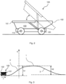
- FIG. 3 illustrates an autonomous working machine 100, such as the working machine 100 illustrated in Fig. 1 and/or 2, which is about to travel through an expected travelling path 1 comprising an uphill road segment 2 followed by a downhill road segment 3.
- the working machine 100 is positioned such that its first end 101 is a leading end.
- the processing circuitry 402 is configured to determine a longitudinal gradient along the expected travelling path 1 of the working machine 100, i.e., the gradient of the ground surface in a direction of travel v of the working machine 100. For example, it may use the data provided from the sensor 114 to localize the working machine 100 within the confined area and based on the position and on the map of the confined area determine the gradient along the expected travelling path 1.
- the processing circuitry 402 is further configured to determine charge levels of the first and second electric energy storage systems, respectively, i.e., of the first battery packs 211a, 211b and of the second battery packs 221a, 221b.
- the charge level may herein be understood as a state-of-charge (SoC) of the respective electric energy storage system.
- SoC state-of-charge
- the charge levels may be determined based on data communicated from the battery packs 211a, 211b, 221a, 221b.
- the processing circuitry 402 is further configured to control the working machine 100 to assume a first orientation or a second orientation to travel along the expected travelling path.
- first orientation as illustrated in Fig. 3 , the first end 101 of the working machine 100 is the leading end, and in the second orientation, the second end 102 of the working machine 100 is the leading end.
- the orientation of the working machine 100 is controlled in dependence on the determined longitudinal gradient and the determined charge levels.
- an uphill road segment 2 may be detected along the expected travelling path 1, such as a road segment over which a vertical height h increases by at least a first threshold height h1. Furthermore, it may be determined that the charge level of the first electric energy storage system 211a, 211b exceeds the charge level of the second electric energy storage system 221a, 221b by at least a first threshold amount. In response thereto, the processing circuitry 402 may control the working machine 100 to assume the second orientation prior to entering the detected uphill road segment 2. In other words, the working machine 100 may travel up the uphill road segment 2 in the second orientation, with the second end 102 being the leading end.
- the first electric motor 212 driving the first axle 110 which is located at a lower level than the second axle 120 during the climb, will hence consume more electric power during the climb than the second electric motor 222. This may contribute to balancing the charge levels, since the charge level of the first electric energy storage system 211a, 211b will decrease more rapidly than the charge level of the second electric energy storage system 221a, 221b.
- the processing circuitry 402 may control the working machine 100 to assume the first orientation prior to entering the detected uphill road segment 2.
- the working machine 100 may be controlled to climb the detected uphill road segment 2 without changing its orientation prior to the climb.
- the first threshold height h1 may be set in dependence on a working machine weight, i.e., a weight of the working machine 100, in such a way that it decreases with increasing working machine weight. If the working machine 100 is relatively light, a relatively large change in vertical height h is thereby required to change orientation of the working machine 100, while for a relatively heavy working machine 100, a relatively small change in vertical height h is required to change orientation. The heavier the working machine 100 is, the larger is the difference between the electric power consumed by the foremost electric motor and the rearmost electric motor.
- a downhill road segment 3 may be detected along the expected travelling path 1, such as a road segment over which the vertical height h decreases by at least a second threshold height h2. Furthermore, it may be determined that the charge level of the first electric energy storage system 211a, 211b exceeds the charge level of the second electric energy storage system 221a, 221b by at least a second threshold amount. In response thereto, the processing circuitry 402 may control the working machine 100 to assume the second orientation prior to entering the detected downhill road segment 3. In other words, the working machine 100 may travel down the downhill road segment 3 in the second orientation, with the second end 102 being the leading end.
- the first electric motor 212 connected to the first axle 110 which is located at a higher level than the second axle 120 during the descent, will hence generate less electric power during the descent than the second electric motor 222. This may contribute to balancing the charge levels, since the charge level of the first electric energy storage system 211a, 211b will increase more slowly than the charge level of the second electric energy storage system 221a, 221b.
- the processing circuitry 402 may control the working machine 100 to assume the first orientation prior to entering the detected downhill road segment 3.
- the working machine 100 may be controlled to descend the detected downhill road segment 3 without changing its orientation prior to the descent.
- the second threshold amount may be equal to the first threshold amount, or it may differ from the first threshold amount.
- the second threshold height h2 may be set in dependence on a working machine weight in such a way that it decreases with increasing working machine weight.
- the first and second threshold heights may or may not be identical.
- the processing circuitry 402 may further be configured to assess whether a first predetermined condition for allowing the working machine 100 to travel through the downhill road segment 3 in the second orientation is fulfilled. If the first predetermined condition is fulfilled, the working machine 100 may be controlled to assume the second orientation. In this example, if the first predetermined condition is not fulfilled, the working machine 100 will not be allowed to descend the downhill road segment 3 in the second orientation.
- the first predetermined condition may be related to the working machine weight and/or to the longitudinal gradient within the downhill road segment 3.
- the first predetermined condition may be considered fulfilled when the longitudinal gradient within the downhill road segment 3 is lower than a threshold gradient, and/or when the longitudinal gradient is not expected to result in a longitudinal inclination of the working machine 100 above a threshold inclination, and/or when the working machine weight is below a threshold weight.
- a threshold gradient By setting such a condition, situations in which a heavily loaded working machine 100 descends in an unsuitable orientation may be avoided.
- the working machine 100 comprises a tiltable body 103 as illustrated in Fig. 2
- material loaded on the tiltable body 103 may fall off the body during the descent in the event of a sudden braking of the working machine 100, depending on a configuration of the tiltable body 103. Hence, it may be more suitable for the working machine 100 to travel downhill in the first orientation.
- the processing circuitry 402 may further be configured to assess whether a second predetermined condition for allowing the working machine 100 to travel through the uphill road segment 2 in the first orientation is fulfilled. If the second predetermined condition is fulfilled, the working machine 100 may be controlled to assume the first orientation. In this example, if the second predetermined condition is not fulfilled, the working machine 100 will not be allowed to ascend the uphill road segment 2 in the first orientation.
- the second predetermined condition may be set to avoid dropping of payload in connection with acceleration of the working machine in the travelling direction during the uphill travel.
- the second predetermined condition may hence be related to the working machine weight and/or to the longitudinal gradient within the uphill road segment 2.
- the second predetermined condition may be set to allow steeper gradients and larger payloads than the first predetermined condition for downhill travel.
- FIG. 4 schematically illustrates a computer-implemented method for controlling the electric propulsion system 200 of an autonomous working machine 100, such as the working machine illustrated in any one of Figs. 1-3 .
- the method comprises the following actions, which may be taken in any suitable order:
- S1 By a processing circuitry 402 of a computer system 400, determining a longitudinal gradient along an expected travelling path 1 of the working machine 100.
- S3 By the processing circuitry 402, controlling the working machine 100 to assume a first orientation or a second orientation to travel along the expected travelling path 1, the first end 101 of the working machine 100 being a leading end in the first orientation, and the second end 102 of the working machine 100 being a leading end in the second orientation, wherein the orientation of the working machine 100 is controlled in dependence on the determined longitudinal gradient and the determined charge levels.
- the method may optionally comprise, by the processing circuitry 402, detecting an uphill road segment 2 along the expected travelling path 1.
- the method may comprise controlling, by the processing circuitry 402, the working machine 100 to assume the second orientation prior to entering the detected uphill road segment 2.
- the method may comprise controlling, by the processing circuitry 402, the working machine 100 to assume the first orientation prior to entering the detected uphill road segment 2.
- the method may further optionally comprise, by the processing circuitry 402, detecting a downhill road segment 3 along the expected travelling path.
- the method may comprise controlling, by the processing circuitry 402, the working machine 100 to assume the second orientation prior to entering the downhill road segment 3.
- the method may comprise controlling, by the processing circuitry 402, the working machine 100 to assume the first orientation prior to entering the detected downhill road segment 3.
- the method may further comprise, by the processing circuitry 402, assessing whether a first predetermined condition for allowing the working machine 100 to travel through the downhill road segment 3 in the second orientation is fulfilled, wherein controlling the working machine 100 to assume the second orientation is only performed if the first predetermined condition is fulfilled.
- the uphill road segment 2 when the uphill road segment 2 has been detected along the expected travelling path, it may further comprise, by the processing circuitry 402, assessing whether a second predetermined condition for allowing the working machine 100 to travel through the uphill road segment 2 in the first orientation is fulfilled, wherein controlling the working machine 100 to assume the first orientation is only performed if the second predetermined condition is fulfilled.
- FIG. 5 is a schematic diagram of a computer system 400 for implementing examples disclosed herein.
- the computer system 400 is adapted to execute instructions from a computer-readable medium to perform these and/or any of the functions or processing described herein.
- the computer system 400 may be connected (e.g., networked) to other machines in a LAN, an intranet, an extranet, or the Internet. While only a single device is illustrated, the computer system 400 may include any collection of devices that individually or jointly execute a set (or multiple sets) of instructions to perform any one or more of the methodologies discussed herein.
- any reference in the disclosure and/or claims to a computer system, computing system, computer device, computing device, control system, control unit, electronic control unit (ECU), processor device, processing circuitry, etc. includes reference to one or more such devices to individually or jointly execute a set (or multiple sets) of instructions to perform any one or more of the methodologies discussed herein.
- control system may include a single control unit or a plurality of control units connected or otherwise communicatively coupled to each other, such that any performed function may be distributed between the control units as desired.
- such devices may communicate with each other or other devices by various system architectures, such as directly or via a Controller Area Network (CAN) bus, etc.
- CAN Controller Area Network
- the computer system 400 may comprise at least one computing device or electronic device capable of including firmware, hardware, and/or executing software instructions to implement the functionality described herein.
- the computer system 400 may include processing circuitry 402 (e.g., processing circuitry including one or more processor devices or control units), a memory 404, and a system bus 406.
- the computer system 400 may include at least one computing device having the processing circuitry 402.
- the system bus 406 provides an interface for system components including, but not limited to, the memory 404 and the processing circuitry 402.
- the processing circuitry 402 may include any number of hardware components for conducting data or signal processing or for executing computer code stored in memory 404.
- the processing circuitry 402 may, for example, include a general-purpose processor, an application specific processor, a Digital Signal Processor (DSP), an Application Specific Integrated Circuit (ASIC), a Field Programmable Gate Array (FPGA), a circuit containing processing components, a group of distributed processing components, a group of distributed computers configured for processing, or other programmable logic device, discrete gate or transistor logic, discrete hardware components, or any combination thereof designed to perform the functions described herein.
- the processing circuitry 402 may further include computer executable code that controls operation of the programmable device.
- the system bus 406 may be any of several types of bus structures that may further interconnect to a memory bus (with or without a memory controller), a peripheral bus, and/or a local bus using any of a variety of bus architectures.
- the memory 404 may be one or more devices for storing data and/or computer code for completing or facilitating methods described herein.
- the memory 404 may include database components, object code components, script components, or other types of information structure for supporting the various activities herein. Any distributed or local memory device may be utilized with the systems and methods of this description.
- the memory 404 may be communicably connected to the processing circuitry 402 (e.g., via a circuit or any other wired, wireless, or network connection) and may include computer code for executing one or more processes described herein.
- the memory 404 may include non-volatile memory 408 (e.g., read-only memory (ROM), erasable programmable read-only memory (EPROM), electrically erasable programmable read-only memory (EEPROM), etc.), and volatile memory 410 (e.g., random-access memory (RAM)), or any other medium which can be used to carry or store desired program code in the form of machine-executable instructions or data structures and which can be accessed by a computer or other machine with processing circuitry 402.
- a basic input/output system (BIOS) 412 may be stored in the non-volatile memory 408 and can include the basic routines that help to transfer information between elements within the computer system 400.
- BIOS basic input/output system
- the computer system 400 may further include or be coupled to a non-transitory computer-readable storage medium such as the storage device 414, which may comprise, for example, an internal or external hard disk drive (HDD) (e.g., enhanced integrated drive electronics (EIDE) or serial advanced technology attachment (SATA)), HDD (e.g., EIDE or SATA) for storage, flash memory, or the like.
- HDD enhanced integrated drive electronics
- SATA serial advanced technology attachment
- the storage device 414 and other drives associated with computer-readable media and computer-usable media may provide non-volatile storage of data, data structures, computer-executable instructions, and the like.
- Computer-code which is hard or soft coded may be provided in the form of one or more modules.
- the module(s) can be implemented as software and/or hard-coded in circuitry to implement the functionality described herein in whole or in part.
- the modules may be stored in the storage device 414 and/or in the volatile memory 410, which may include an operating system 416 and/or one or more program modules 418.
- All or a portion of the examples disclosed herein may be implemented as a computer program 420 stored on a transitory or non-transitory computer-usable or computer-readable storage medium (e.g., single medium or multiple media), such as the storage device 414, which includes complex programming instructions (e.g., complex computer-readable program code) to cause the processing circuitry 402 to carry out actions described herein.
- the computer-readable program code of the computer program 420 can comprise software instructions for implementing the functionality of the examples described herein when executed by the processing circuitry 402.
- the storage device 414 may be a computer program product (e.g., readable storage medium) storing the computer program 420 thereon, where at least a portion of a computer program 420 may be loadable (e.g., into a processor) for implementing the functionality of the examples described herein when executed by the processing circuitry 402.
- the processing circuitry 402 may serve as a controller or control system for the computer system 400 that is to implement the functionality described herein.
- the computer system 400 may include an input device interface 422 configured to receive input and selections to be communicated to the computer system 400 when executing instructions, such as from a keyboard, mouse, touch-sensitive surface, etc. Such input devices may be connected to the processing circuitry 402 through the input device interface 422 coupled to the system bus 406 but can be connected through other interfaces, such as a parallel port, an Institute of Electrical and Electronic Engineers (IEEE) 1394 serial port, a Universal Serial Bus (USB) port, an IR interface, and the like.
- the computer system 400 may include an output device interface 424 configured to forward output, such as to a display, a video display unit (e.g., a liquid crystal display (LCD) or a cathode ray tube (CRT)).
- the computer system 400 may include a communications interface 426 suitable for communicating with a network as appropriate or desired.
- a computer system (400) comprising processing circuitry (402) configured to control an electric propulsion system (200) of an autonomous working machine (100) comprising a first axle (110) located near a first end (101) of the working machine (100) and a second axle (120) located near a second end (102) of the working machine (100), the electric propulsion system (200) comprising:
- Example 2 The computer system of example 1, wherein the processing circuitry (402) is further configured to:
- Example 3 The computer system of example 2, wherein the uphill road segment (2) is a road segment over which a vertical height (h) increases by at least a first threshold height (h1).
- Example 4 The computer system of example 3, wherein the first threshold height (h1) is set in dependence on a working machine weight in such a way that it decreases with increasing working machine weight.
- Example 5 The computer system of any of the preceding examples, wherein the processing circuitry (402) is configured to:
- Example 6 The computer system of example 5, wherein the downhill road segment (3) is a road segment over which a vertical height (h) decreases by at least a second threshold height (h2), optionally wherein the second threshold height (h2) is set in dependence on a working machine weight in such a way that it decreases with increasing working machine weight.
- the second threshold height (h2) is set in dependence on a working machine weight in such a way that it decreases with increasing working machine weight.
- Example 7 The computer system of example 5 or 6, wherein the processing circuitry (402) is further configured to:
- Example 8 The computer system of example 7, wherein the predetermined condition is related to a working machine weight and/or to the longitudinal gradient within the downhill road segment.
- Example 9 The computer system of example 7 or 8, wherein the predetermined condition is considered fulfilled when the longitudinal gradient within the downhill road segment (3) is lower than a threshold gradient, and/or when the longitudinal gradient is not expected to result in a working machine inclination above a threshold inclination, and/or when the working machine weight is below a threshold weight.
- Example 10 An autonomous working machine (100) comprising or being communicatively connected to the computer system (400) of any of examples 1-9.
- Example 11 The working machine of example 10, wherein the working machine (100) comprises a tiltable body (103) configured to carry a payload, the tiltable body (103) being pivotable about a transverse axis located at the second end (102) of the working machine (100).
- Example 12 A computer-implemented method for controlling an electric propulsion system (200) of an autonomous working machine (100) comprising a first axle (110) located near a first end (101) of the working machine (100) and a second axle (120) located near a second end (102) of the working machine (100), the electric propulsion system (200) comprising:
- Example 13 The method of example 12, comprising:
- Example 14 The method of example 13, wherein detecting the uphill road segment (2) comprises detecting a road segment over which a vertical height (h) increases by at least a first threshold height (h1).
- Example 15 The method of example 14, wherein the first threshold height (h1) is set in dependence on a working machine weight in such a way that it decreases with increasing working machine weight.
- Example 16 The method of any of examples 12-15, comprising:
- Example 17 The method of example 16, wherein detecting the downhill road segment (3) comprises detecting a road segment over which a vertical height (h) decreases by at least a second threshold height (h2).
- Example 18 The method of example 16 or 17, further comprising:
- Example 19 The method of example 18, wherein the predetermined condition is related to a working machine payload and/or to the longitudinal gradient within the downhill road segment (3).
- Example 20 The method of example 18 or 19, wherein the predetermined condition is considered fulfilled when the longitudinal gradient within the downhill road segment (3) is lower than a threshold gradient, and/or when the longitudinal gradient is not expected to result in a working machine inclination above a threshold inclination, and/or when the working machine weight is below a threshold weight.
- Example 21 A computer program product comprising program code for performing, when executed by the processing circuitry (402), the method of any of examples 12-20.
- Example 22 A non-transitory computer-readable storage medium comprising instructions, which when executed by the processing circuitry (402), cause the processing circuitry to perform the method of any of examples 12-20.
- Relative terms such as “below” or “above” or “upper” or “lower” or “horizontal” or “vertical” may be used herein to describe a relationship of one element to another element as illustrated in the Figures. It will be understood that these terms and those discussed above are intended to encompass different orientations of the device in addition to the orientation depicted in the Figures. It will be understood that when an element is referred to as being “connected” or “coupled” to another element, it can be directly connected or coupled to the other element, or intervening elements may be present. In contrast, when an element is referred to as being “directly connected” or “directly coupled” to another element, there are no intervening elements present.
Landscapes
- Engineering & Computer Science (AREA)
- Transportation (AREA)
- Mechanical Engineering (AREA)
- Power Engineering (AREA)
- Life Sciences & Earth Sciences (AREA)
- Sustainable Development (AREA)
- Sustainable Energy (AREA)
- Combustion & Propulsion (AREA)
- Chemical & Material Sciences (AREA)
- Automation & Control Theory (AREA)
- Human Computer Interaction (AREA)
- Electric Propulsion And Braking For Vehicles (AREA)
- Operation Control Of Excavators (AREA)
- Hybrid Electric Vehicles (AREA)
Abstract
A computer system (400) and a method for control of an electric propulsion system (200) of an autonomous working machine (100) comprising a first axle (110) and a second axle (120), the electric propulsion system comprising:- a first electric system (210) configured to drive the first axle, comprising a first electric energy storage system (211a, 211b),- a second electric system (220) configured to drive the second axle, comprising a second electric energy storage system (221a, 221b).The method comprises:- determining a longitudinal gradient along an expected travelling path,- determining charge levels of the first and second electric energy storage systems, respectively,- controlling the working machine to assume a first orientation or a second orientation to travel along the expected travelling path, wherein the orientation of the working machine is controlled in dependence on the determined longitudinal gradient and the determined charge levels.
Description
- The disclosure relates generally to control of electric propulsion systems in autonomous working machines. In particular aspects, the disclosure relates to a computer system and a method for controlling an electric propulsion system of an autonomous working machine. The disclosure can be applied to heavy-duty working machines and construction equipment, among other vehicle types. Although the disclosure may be described with respect to a particular working machine, the disclosure is not restricted to any particular working machine.
- Heavy-duty electric working machines, such as electrically powered hauler vehicles and dump trucks, usually comprise more than one driven axle, such as two driven axles. Such working machines may either comprise a single electric system powering both axles, or separate electric systems, each powering one of the axles. A problem that may arise when separate electric systems are provided is that battery packs of the respective electric systems may discharge unevenly, i.e., battery packs used for powering a rear axle of the working machine may discharge more rapidly than battery packs used for powering a front axle. A charging stop may hence be necessary before the battery packs used for powering the front axle are fully discharged.
- According to a first aspect of the disclosure, a computer system comprising processing circuitry configured to control an electric propulsion system of an autonomous working machine comprising a first axle located near a first end of the working machine and a second axle located near a second end of the working machine is provided. The electric propulsion system comprises:
- a first electric system configured to drive the first axle, the first electric system comprising a first electric energy storage system and a first electric motor,
- a second electric system configured to drive the second axle, the second electric system comprising a second electric energy storage system and a second electric motor.
- The processing circuitry is configured to:
- determine a longitudinal gradient along an expected travelling path of the working machine,
- determine charge levels of the first and second electric energy storage systems, respectively,
- control the working machine to assume a first orientation or a second orientation to travel along the expected travelling path, the first end of the working machine being a leading end in the first orientation, and the second end of the working machine being a leading end in the second orientation, wherein the orientation of the working machine is controlled in dependence on the determined longitudinal gradient and the determined charge levels.
- The first aspect of the disclosure may seek to provide an in at least some aspect improved system for controlling an electric propulsion system comprising two separate electric systems configured to drive two separate axles. In particular, the first aspect may seek to provide such a system which may reduce problems with unbalanced charge levels between the respective energy storage systems of the two electric systems and which may hence increase the time between charging stops. By controlling the working machine to assume an orientation in dependence on the charge levels and the road gradient, the orientation may be selected to balance the charge levels between the energy storage systems. For an autonomous working machine, the orientation for travelling up or down a hill may hence be selected for charge balancing purposes. A technical benefit may include an improved total battery range of the working machine.
- Optionally in some examples, including in at least one preferred example, the processing circuitry is further configured to:
- detect an uphill road segment along the expected travelling path,
- in response to determining that the charge level of the first electric energy storage system exceeds the charge level of the second electric energy storage system by at least a first threshold amount, control the working machine to assume the second orientation prior to entering the detected uphill road segment, and
- in response to determining that the charge level of the second electric energy storage system exceeds the charge level of the first electric energy storage system by at least the first threshold amount, control the working machine to assume the first orientation prior to entering the detected uphill road segment.
- Hence, an orientation of the working machine for travelling through the uphill road segment may be selected such that the energy storage system having the lowest charge level provides less electric power during the uphill travel than the energy storage system having the highest charge level. This may contribute to balancing of the charge levels. When it is determined that the charge levels of the energy storage systems differ by less than the first threshold amount, the working machine may be controlled to keep its present orientation. In this way, it can be ensured that a change of orientation is only initiated when it is considered useful.
- Optionally in some examples, including in at least one preferred example, the uphill road segment is a road segment over which a vertical height increases by at least a first threshold height. In this way, it can be ensured that a change of orientation is not initiated when the potential for balancing the charge levels is considered too low.
- Optionally in some examples, including in at least one preferred example, the first threshold height is set in dependence on a working machine weight in such a way that it decreases with increasing working machine weight. Hence, the larger the payload of the working machine, the less height difference is required for the road segment to be detected as an uphill road segment prior to which the working machine change its orientation.
- Optionally in some examples, including in at least one preferred example, the processing circuitry is configured to:
- detect a downhill road segment along the expected travelling path,
- in response to determining that the charge level of the first electric energy storage system exceeds the charge level of the second electric energy storage system by at least a second threshold amount, control the working machine to assume the second orientation prior to entering the detected downhill road segment, and
- in response to determining that the charge level of the second electric energy storage system exceeds the charge level of the first electric energy storage system by at least the second threshold amount, control the working machine to assume the first orientation prior to entering the detected downhill road segment.
- Hence, an orientation of the working machine for travelling through the downhill road segment may be selected such that energy recuperated during travel along the downhill road segment is primarily used for charging of the energy storage system having the lowest charge level. This may contribute to balancing of the charge levels. When it is determined that the charge levels of the energy storage systems differ by less than the second threshold amount, the working machine may be controlled to keep its present orientation. In this way, it can be ensured that a change of orientation is only initiated when it is considered useful.
- Optionally in some examples, including in at least one preferred example, the downhill road segment is a road segment over which a vertical height decreases by at least a second threshold height. Optionally, the second threshold height is set in dependence on a working machine weight in such a way that it decreases with increasing working machine weight.
- Optionally in some examples, including in at least one preferred example, the processing circuitry is further configured to assess whether a predetermined condition for allowing the working machine to travel through the downhill road segment in the second orientation is fulfilled, wherein the processing circuitry is only configured to control the working machine to assume the second orientation if the predetermined condition is fulfilled. In this way, it can be avoided that the working machine travels through the downhill road segment in the second orientation if it is less suitable due to, e.g., a configuration of the working machine and a gradient of the road. This may be relevant, e.g., if the working machine comprises a tiltable body having a non-symmetric design. In those cases, it may be safer to travel through steep downhill road segments with the first end being a leading end to avoid dropping of payload if the working machine has to brake.
- Optionally in some examples, including in at least one preferred example, the predetermined condition is related to a working machine weight and/or to the longitudinal gradient within the downhill road segment.
- Optionally in some examples, including in at least one preferred example, the predetermined condition is considered fulfilled when the longitudinal gradient within the downhill road segment is lower than a threshold gradient, and/or when the longitudinal gradient is not expected to result in a working machine inclination above a threshold inclination, and/or when the working machine weight is below a threshold weight.
- According to a second aspect of the disclosure, an autonomous working machine comprising or being communicatively connected to the computer system according to the first aspect is provided. The autonomous working machine comprises a first axle located near a first end of the working machine, a second axle located near a second end of the working machine, and an electric propulsion system comprising a first electric system configured to drive the first axle, the first electric system comprising a first electric energy storage system and a first electric motor, and a second electric system configured to drive the second axle, the second electric system comprising a second electric energy storage system and a second electric motor. The second aspect of the disclosure may seek to provide an in at least some aspect improved autonomous working machine of this type. In particular, it may seek to provide an autonomous working machine in which problems with unbalanced charge levels between the respective energy storage systems of the two electric systems may be reduced.
- Optionally in some examples, including in at least one preferred example, the working machine comprises a tiltable body configured to carry a payload, the tiltable body being pivotable about a transverse axis located at the second end of the working machine. Hence, the first end may correspond to a front end of the working machine, and the second end may correspond to a rear end.
- According to a third aspect of the disclosure, a computer-implemented method for controlling an electric propulsion system of an autonomous working machine comprising a first axle located near a first end of the working machine and a second axle located near a second end of the working machine is provided. The electric propulsion system comprises:
- a first electric system configured to drive the first axle, the first electric system comprising a first electric energy storage system and a first electric motor,
- a second electric system configured to drive the second axle, the second electric system comprising a second electric energy storage system and a second electric motor.
- The method comprises:
- by a processing circuitry of a computer system, determining a longitudinal gradient along an expected travelling path of the working machine,
- by the processing circuitry, determining charge levels of the first and second electric energy storage systems, respectively,
- by the processing circuitry, controlling the working machine to assume a first orientation or a second orientation to travel along the expected travelling path, the first end of the working machine being a leading end in the first orientation, and the second end of the working machine being a leading end in the second orientation, wherein the orientation of the working machine is controlled in dependence on the determined longitudinal gradient and the determined charge levels.
- Advantages and effects of the third aspect of the disclosure are analogous to the advantages and effects of the first and second aspects of the disclosure, and vice versa.
- Optionally in some examples, including in at least one preferred example, the method comprises:
- by the processing circuitry, detecting an uphill road segment along the expected travelling path,
- in response to determining that the charge level of the first electric energy storage system exceeds the charge level of the second electric energy storage system by at least a first threshold amount, controlling, by the processing circuitry, the working machine to assume the second orientation prior to entering the detected uphill road segment, and
- in response to determining that the charge level of the second electric energy storage system exceeds the charge level of the first electric energy storage system by at least the first threshold amount, controlling, by the processing circuitry the working machine to assume the first orientation prior to entering the detected uphill road segment.
- Optionally in some examples, including in at least one preferred example, detecting the uphill road segment comprises detecting a road segment over which a vertical height increases by at least a first threshold height.
- Optionally in some examples, including in at least one preferred example, the first threshold height is set in dependence on a working machine weight in such a way that it decreases with increasing working machine weight.
- Optionally in some examples, including in at least one preferred example, the method comprises:
- by the processing circuitry, detecting a downhill road segment along the expected travelling path,
- in response to determining that the charge level of the first electric energy storage system exceeds the charge level of the second electric energy storage system by at least a second threshold amount, controlling, by the processing circuitry, the working machine to assume the second orientation prior to entering the downhill road segment, and
- in response to determining that the charge level of the second electric energy storage system exceeds the charge level of the first electric energy storage system by at least the second threshold amount, controlling, by the processing circuitry, the working machine to assume the first orientation prior to entering the detected downhill road segment.
- Optionally in some examples, including in at least one preferred example, detecting the downhill road segment comprises detecting a road segment over which a vertical height decreases by at least a second threshold height.
- Optionally in some examples, including in at least one preferred example, the method further comprises:
- by the processing circuitry, assessing whether a predetermined condition for allowing the working machine to travel through the downhill road segment in the second orientation is fulfilled,
- Optionally in some examples, including in at least one preferred example, the predetermined condition is related to a working machine payload and/or to the longitudinal gradient within the downhill road segment.
- Optionally in some examples, including in at least one preferred example, the predetermined condition is considered fulfilled when the longitudinal gradient within the downhill road segment is lower than a threshold gradient, and/or when the longitudinal gradient is not expected to result in a working machine inclination above a threshold inclination, and/or when the working machine weight is below a threshold weight.
- According to a fourth aspect of the disclosure, there is provided a computer program product comprising program code for performing, when executed by the processing circuitry, the method of any of the examples of the third aspect of the disclosure.
- According to a fifth aspect of the disclosure, there is provided a non-transitory computer-readable storage medium comprising instructions, which when executed by the processing circuitry, cause the processing circuitry to perform the method of any of the examples of the third aspect of the disclosure.
- The disclosed aspects, examples (including any preferred examples), and/or accompanying claims may be suitably combined with each other as would be apparent to anyone of ordinary skill in the art. Additional features and advantages are disclosed in the following description, claims, and drawings, and in part will be readily apparent therefrom to those skilled in the art or recognized by practicing the disclosure as described herein.
- There are also disclosed herein computer systems, control units, code modules, computer-implemented methods, computer readable media, and computer program products associated with the above discussed technical benefits.
- Examples are described in more detail below with reference to the appended drawings.
-
Fig. 1 is a schematic overview of an autonomous working machine and a computer system according to an example. -
Fig. 2 is a schematic side view of an autonomous working machine according to an example. -
Fig. 3 schematically illustrates an autonomous working machine about to travel up a hill. -
Fig. 4 is a flowchart illustrating a method according to an example. -
Fig. 5 is a schematic diagram of an exemplary computer system for implementing examples disclosed herein, according to an example. - The detailed description set forth below provides information and examples of the disclosed technology with sufficient detail to enable those skilled in the art to practice the disclosure.
- An electrically powered working machine may comprise two electric systems, each powering one driven axle of the working machine, such as a front axle and a rear axle. Each electric system comprises its own electric energy storage system, which may be charged at an electric charging station and in which energy recuperated during, e.g., downhill travel may be stored. Since front and rear axle propulsion and energy recuperation do not necessarily follow each other, there will over time build up a difference in charge levels for the front and the rear electric energy storage systems, even when the charge levels were equal after charging at the charging station. Typical occasions that build up such a difference in charge levels are driving uphill or downhill with poor traction. In these cases, tractive force must be distributed according to the normal force distribution to utilize the available friction. Accordingly, more power is consumed by the rear axle propulsion system when driving uphill and more power is recuperated by the front axle propulsion system when driving downhill. This will drain the rear axle electric energy storage system and lead to a charging stop before the charge level of the front axle electric energy storage system is low.
- With separate electric systems, it is normally not possible to transfer electric power from one of the electric energy storage systems to the other when the charge levels begin to differ from one another. Instead, when one of the electric energy storage systems is depleted, a charging stop is necessary, even if the other electric energy storage system still has available electric power.
- To reduce downtime, it is desirable to provide a method and a system that contribute to balancing of the charge levels of the two electric energy storage systems.
-
FIG. 1 schematically illustrates anautonomous working machine 100 being communicatively connected to acomputer system 400 according to an example of the disclosure. The workingmachine 100 comprises afirst axle 110 located near afirst end 101 of the workingmachine 100 and asecond axle 120 located near asecond end 102 of the workingmachine 100. A first pair of drivenwheels first axle 110, and a second pair of drivenwheels second axle 120. The workingmachine 100 further comprises anelectric propulsion system 200 for providing propulsion power to the workingmachine 100. Theelectric propulsion system 200 comprises a firstelectric system 210 configured to drive thefirst axle 110, and a secondelectric system 220 configured to drive thesecond axle 120. The firstelectric system 210 comprises a first electric energy storage system, herein comprising twofirst battery packs electric motor 212. The secondelectric system 220 comprises a second electric energy storage system, herein comprising twosecond battery packs electric motor 222. The firstelectric motor 212 is connected to thefirst axle 110 via afirst transmission 113 and the secondelectric motor 222 is connected to thesecond axle 120 via asecond transmission 123. The first and secondelectric motors - Although the first and second
electric systems electric motor - The
computer system 400 comprises aprocessing circuitry 402 and may be located on-board or off-board the workingmachine 100. For example, thecomputer system 400 may be a central server or a cloud server and arranged to communicate with an on-board control unit 130 of the workingmachine 100. The communicative contact between thecomputer system 400 and thecontrol unit 130 of the workingmachine 100, indicated by a dashed arrow, may be in the form of wireless communication, such as by use of WiFi, Bluetooth, telecommunication, etc. The on-board control unit 130 may in turn be configured to communicate with different systems of the workingmachine 100, such as with the first and secondelectric systems - The
autonomous working machine 100 illustrated inFig. 1 may, e.g., have a configuration such as schematically illustrated inFIG. 2 . Hence, the workingmachine 100 may comprise atiltable body 103 configured to carry a payload. Thetiltable body 103 may be pivotable about a transverse axis (not shown) located at thesecond end 102 of the workingmachine 100. The transverse axis is herein parallel to the first andsecond axles - The working
machine 100 may be configured for operation in a confined area, such as in a working site, a quarry, a mine, or similar. A site system of the confined area may be available to thecomputer system 400. The site system may comprise a map of the confined area, including a topographic map from which road gradients along known travelling paths for the workingmachine 100 are known. Thecomputer system 400 may be configured to plan a travelling path of the workingmachine 100 based on information provided from the site system. The workingmachine 100 may further comprise at least onesensor 114 for identifying a position of the workingmachine 100 in the confined area. Thesensor 114 may for example be a GNSS (global navigation satellite system) sensor. Thesensor 114 may be configured to communicate the coordinates of the workingmachine 100 to thecomputer system 400. Additionally, or alternatively, other sensors may be used for localizing the workingmachine 100 in the confined area, such as by use of environment perception sensors. - The working
machine 100 may furthermore comprise at least onesensor 115 for detecting a weight of the workingmachine 100 and/or of a load provided on the workingmachine 100, i.e., material loaded on the workingmachine 100. Thesensor 115 may for example be a weight sensor which measures a weight of the load. Alternatively, by using pressure sensors, the sprung weight of the working machine may be calculated from measured pressures in a hydraulic suspension system. Furthermore, a camera or similar identifying material loaded onto the workingmachine 100 may be provided. Data from thesensor 115 may be communicated to thecomputer system 400. - The working
machine 100 may furthermore comprise at least one sensor (not shown) by means of which a present orientation of the working machine may be determined. The sensor may, e.g., be a rotational speed sensor configured to sense rotational speed of any one of thewheels machine 100. -
FIG. 3 illustrates anautonomous working machine 100, such as the workingmachine 100 illustrated inFig. 1 and/or 2, which is about to travel through an expected travellingpath 1 comprising anuphill road segment 2 followed by adownhill road segment 3. The workingmachine 100 is positioned such that itsfirst end 101 is a leading end. - The
processing circuitry 402 is configured to determine a longitudinal gradient along the expected travellingpath 1 of the workingmachine 100, i.e., the gradient of the ground surface in a direction of travel v of the workingmachine 100. For example, it may use the data provided from thesensor 114 to localize the workingmachine 100 within the confined area and based on the position and on the map of the confined area determine the gradient along the expected travellingpath 1. - The
processing circuitry 402 is further configured to determine charge levels of the first and second electric energy storage systems, respectively, i.e., of thefirst battery packs second battery packs battery packs - The
processing circuitry 402 is further configured to control the workingmachine 100 to assume a first orientation or a second orientation to travel along the expected travelling path. In the first orientation, as illustrated inFig. 3 , thefirst end 101 of the workingmachine 100 is the leading end, and in the second orientation, thesecond end 102 of the workingmachine 100 is the leading end. The orientation of the workingmachine 100 is controlled in dependence on the determined longitudinal gradient and the determined charge levels. - In one example, an
uphill road segment 2 may be detected along the expected travellingpath 1, such as a road segment over which a vertical height h increases by at least a first threshold height h1. Furthermore, it may be determined that the charge level of the first electricenergy storage system energy storage system processing circuitry 402 may control the workingmachine 100 to assume the second orientation prior to entering the detecteduphill road segment 2. In other words, the workingmachine 100 may travel up theuphill road segment 2 in the second orientation, with thesecond end 102 being the leading end. The firstelectric motor 212, driving thefirst axle 110 which is located at a lower level than thesecond axle 120 during the climb, will hence consume more electric power during the climb than the secondelectric motor 222. This may contribute to balancing the charge levels, since the charge level of the first electricenergy storage system energy storage system - Correspondingly, if it is determined that the charge level of the second electric
energy storage system energy storage system processing circuitry 402 may control the workingmachine 100 to assume the first orientation prior to entering the detecteduphill road segment 2. - If the difference between the charge levels of the first electric
energy storage system energy storage system machine 100 may be controlled to climb the detecteduphill road segment 2 without changing its orientation prior to the climb. - The first threshold height h1 may be set in dependence on a working machine weight, i.e., a weight of the working
machine 100, in such a way that it decreases with increasing working machine weight. If the workingmachine 100 is relatively light, a relatively large change in vertical height h is thereby required to change orientation of the workingmachine 100, while for a relatively heavy workingmachine 100, a relatively small change in vertical height h is required to change orientation. The heavier the workingmachine 100 is, the larger is the difference between the electric power consumed by the foremost electric motor and the rearmost electric motor. - In another example, a
downhill road segment 3 may be detected along the expected travellingpath 1, such as a road segment over which the vertical height h decreases by at least a second threshold height h2. Furthermore, it may be determined that the charge level of the first electricenergy storage system energy storage system processing circuitry 402 may control the workingmachine 100 to assume the second orientation prior to entering the detecteddownhill road segment 3. In other words, the workingmachine 100 may travel down thedownhill road segment 3 in the second orientation, with thesecond end 102 being the leading end. The firstelectric motor 212, connected to thefirst axle 110 which is located at a higher level than thesecond axle 120 during the descent, will hence generate less electric power during the descent than the secondelectric motor 222. This may contribute to balancing the charge levels, since the charge level of the first electricenergy storage system energy storage system - Correspondingly, if it is determined that the charge level of the second electric
energy storage system energy storage system processing circuitry 402 may control the workingmachine 100 to assume the first orientation prior to entering the detecteddownhill road segment 3. - If the difference between the charge levels of the first electric
energy storage system energy storage system machine 100 may be controlled to descend the detecteddownhill road segment 3 without changing its orientation prior to the descent. The second threshold amount may be equal to the first threshold amount, or it may differ from the first threshold amount. - Similar to the first threshold height h1, the second threshold height h2 may be set in dependence on a working machine weight in such a way that it decreases with increasing working machine weight. The first and second threshold heights may or may not be identical.
- The
processing circuitry 402 may further be configured to assess whether a first predetermined condition for allowing the workingmachine 100 to travel through thedownhill road segment 3 in the second orientation is fulfilled. If the first predetermined condition is fulfilled, the workingmachine 100 may be controlled to assume the second orientation. In this example, if the first predetermined condition is not fulfilled, the workingmachine 100 will not be allowed to descend thedownhill road segment 3 in the second orientation. The first predetermined condition may be related to the working machine weight and/or to the longitudinal gradient within thedownhill road segment 3. For example, the first predetermined condition may be considered fulfilled when the longitudinal gradient within thedownhill road segment 3 is lower than a threshold gradient, and/or when the longitudinal gradient is not expected to result in a longitudinal inclination of the workingmachine 100 above a threshold inclination, and/or when the working machine weight is below a threshold weight. By setting such a condition, situations in which a heavily loaded workingmachine 100 descends in an unsuitable orientation may be avoided. For example, when the workingmachine 100 comprises atiltable body 103 as illustrated inFig. 2 , material loaded on thetiltable body 103 may fall off the body during the descent in the event of a sudden braking of the workingmachine 100, depending on a configuration of thetiltable body 103. Hence, it may be more suitable for the workingmachine 100 to travel downhill in the first orientation. - Similarly, when the
uphill road segment 2 is detected, theprocessing circuitry 402 may further be configured to assess whether a second predetermined condition for allowing the workingmachine 100 to travel through theuphill road segment 2 in the first orientation is fulfilled. If the second predetermined condition is fulfilled, the workingmachine 100 may be controlled to assume the first orientation. In this example, if the second predetermined condition is not fulfilled, the workingmachine 100 will not be allowed to ascend theuphill road segment 2 in the first orientation. The second predetermined condition may be set to avoid dropping of payload in connection with acceleration of the working machine in the travelling direction during the uphill travel. The second predetermined condition may hence be related to the working machine weight and/or to the longitudinal gradient within theuphill road segment 2. In comparison with downhill travel, the risk of dropping payload is generally lower during uphill travel since the magnitude of the acceleration is typically lower than the magnitude of the deceleration in a sudden braking event during downhill travel. Consequently, the second predetermined condition may be set to allow steeper gradients and larger payloads than the first predetermined condition for downhill travel. -
FIG. 4 schematically illustrates a computer-implemented method for controlling theelectric propulsion system 200 of anautonomous working machine 100, such as the working machine illustrated in any one ofFigs. 1-3 . The method comprises the following actions, which may be taken in any suitable order: - S1: By a
processing circuitry 402 of acomputer system 400, determining a longitudinal gradient along an expected travellingpath 1 of the workingmachine 100. - S2: By the
processing circuitry 402, determining charge levels of the first and second electricenergy storage systems - S3: By the
processing circuitry 402, controlling the workingmachine 100 to assume a first orientation or a second orientation to travel along the expected travellingpath 1, thefirst end 101 of the workingmachine 100 being a leading end in the first orientation, and thesecond end 102 of the workingmachine 100 being a leading end in the second orientation, wherein the orientation of the workingmachine 100 is controlled in dependence on the determined longitudinal gradient and the determined charge levels. - The method may optionally comprise, by the
processing circuitry 402, detecting anuphill road segment 2 along the expected travellingpath 1. In response to determining that the charge level of the first electricenergy storage system energy storage system processing circuitry 402, the workingmachine 100 to assume the second orientation prior to entering the detecteduphill road segment 2. In response to determining that the charge level of the second electricenergy storage system energy storage system processing circuitry 402, the workingmachine 100 to assume the first orientation prior to entering the detecteduphill road segment 2. - The method may further optionally comprise, by the
processing circuitry 402, detecting adownhill road segment 3 along the expected travelling path. In response to determining that the charge level of the first electricenergy storage system energy storage system processing circuitry 402, the workingmachine 100 to assume the second orientation prior to entering thedownhill road segment 3. In response to determining that the charge level of the second electricenergy storage system energy storage system processing circuitry 402, the workingmachine 100 to assume the first orientation prior to entering the detecteddownhill road segment 3. - The method may further comprise, by the
processing circuitry 402, assessing whether a first predetermined condition for allowing the workingmachine 100 to travel through thedownhill road segment 3 in the second orientation is fulfilled, wherein controlling the workingmachine 100 to assume the second orientation is only performed if the first predetermined condition is fulfilled. - Similarly, when the
uphill road segment 2 has been detected along the expected travelling path, it may further comprise, by theprocessing circuitry 402, assessing whether a second predetermined condition for allowing the workingmachine 100 to travel through theuphill road segment 2 in the first orientation is fulfilled, wherein controlling the workingmachine 100 to assume the first orientation is only performed if the second predetermined condition is fulfilled. -
FIG. 5 is a schematic diagram of acomputer system 400 for implementing examples disclosed herein. Thecomputer system 400 is adapted to execute instructions from a computer-readable medium to perform these and/or any of the functions or processing described herein. Thecomputer system 400 may be connected (e.g., networked) to other machines in a LAN, an intranet, an extranet, or the Internet. While only a single device is illustrated, thecomputer system 400 may include any collection of devices that individually or jointly execute a set (or multiple sets) of instructions to perform any one or more of the methodologies discussed herein. Accordingly, any reference in the disclosure and/or claims to a computer system, computing system, computer device, computing device, control system, control unit, electronic control unit (ECU), processor device, processing circuitry, etc., includes reference to one or more such devices to individually or jointly execute a set (or multiple sets) of instructions to perform any one or more of the methodologies discussed herein. For example, control system may include a single control unit or a plurality of control units connected or otherwise communicatively coupled to each other, such that any performed function may be distributed between the control units as desired. Further, such devices may communicate with each other or other devices by various system architectures, such as directly or via a Controller Area Network (CAN) bus, etc. - The
computer system 400 may comprise at least one computing device or electronic device capable of including firmware, hardware, and/or executing software instructions to implement the functionality described herein. Thecomputer system 400 may include processing circuitry 402 (e.g., processing circuitry including one or more processor devices or control units), amemory 404, and asystem bus 406. Thecomputer system 400 may include at least one computing device having theprocessing circuitry 402. Thesystem bus 406 provides an interface for system components including, but not limited to, thememory 404 and theprocessing circuitry 402. Theprocessing circuitry 402 may include any number of hardware components for conducting data or signal processing or for executing computer code stored inmemory 404. Theprocessing circuitry 402 may, for example, include a general-purpose processor, an application specific processor, a Digital Signal Processor (DSP), an Application Specific Integrated Circuit (ASIC), a Field Programmable Gate Array (FPGA), a circuit containing processing components, a group of distributed processing components, a group of distributed computers configured for processing, or other programmable logic device, discrete gate or transistor logic, discrete hardware components, or any combination thereof designed to perform the functions described herein. Theprocessing circuitry 402 may further include computer executable code that controls operation of the programmable device. - The
system bus 406 may be any of several types of bus structures that may further interconnect to a memory bus (with or without a memory controller), a peripheral bus, and/or a local bus using any of a variety of bus architectures. Thememory 404 may be one or more devices for storing data and/or computer code for completing or facilitating methods described herein. Thememory 404 may include database components, object code components, script components, or other types of information structure for supporting the various activities herein. Any distributed or local memory device may be utilized with the systems and methods of this description. Thememory 404 may be communicably connected to the processing circuitry 402 (e.g., via a circuit or any other wired, wireless, or network connection) and may include computer code for executing one or more processes described herein. Thememory 404 may include non-volatile memory 408 (e.g., read-only memory (ROM), erasable programmable read-only memory (EPROM), electrically erasable programmable read-only memory (EEPROM), etc.), and volatile memory 410 (e.g., random-access memory (RAM)), or any other medium which can be used to carry or store desired program code in the form of machine-executable instructions or data structures and which can be accessed by a computer or other machine withprocessing circuitry 402. A basic input/output system (BIOS) 412 may be stored in thenon-volatile memory 408 and can include the basic routines that help to transfer information between elements within thecomputer system 400. - The
computer system 400 may further include or be coupled to a non-transitory computer-readable storage medium such as thestorage device 414, which may comprise, for example, an internal or external hard disk drive (HDD) (e.g., enhanced integrated drive electronics (EIDE) or serial advanced technology attachment (SATA)), HDD (e.g., EIDE or SATA) for storage, flash memory, or the like. Thestorage device 414 and other drives associated with computer-readable media and computer-usable media may provide non-volatile storage of data, data structures, computer-executable instructions, and the like. - Computer-code which is hard or soft coded may be provided in the form of one or more modules. The module(s) can be implemented as software and/or hard-coded in circuitry to implement the functionality described herein in whole or in part. The modules may be stored in the
storage device 414 and/or in thevolatile memory 410, which may include anoperating system 416 and/or one ormore program modules 418. All or a portion of the examples disclosed herein may be implemented as acomputer program 420 stored on a transitory or non-transitory computer-usable or computer-readable storage medium (e.g., single medium or multiple media), such as thestorage device 414, which includes complex programming instructions (e.g., complex computer-readable program code) to cause theprocessing circuitry 402 to carry out actions described herein. Thus, the computer-readable program code of thecomputer program 420 can comprise software instructions for implementing the functionality of the examples described herein when executed by theprocessing circuitry 402. In some examples, thestorage device 414 may be a computer program product (e.g., readable storage medium) storing thecomputer program 420 thereon, where at least a portion of acomputer program 420 may be loadable (e.g., into a processor) for implementing the functionality of the examples described herein when executed by theprocessing circuitry 402. Theprocessing circuitry 402 may serve as a controller or control system for thecomputer system 400 that is to implement the functionality described herein. - The
computer system 400 may include aninput device interface 422 configured to receive input and selections to be communicated to thecomputer system 400 when executing instructions, such as from a keyboard, mouse, touch-sensitive surface, etc. Such input devices may be connected to theprocessing circuitry 402 through theinput device interface 422 coupled to thesystem bus 406 but can be connected through other interfaces, such as a parallel port, an Institute of Electrical and Electronic Engineers (IEEE) 1394 serial port, a Universal Serial Bus (USB) port, an IR interface, and the like. Thecomputer system 400 may include anoutput device interface 424 configured to forward output, such as to a display, a video display unit (e.g., a liquid crystal display (LCD) or a cathode ray tube (CRT)). Thecomputer system 400 may include acommunications interface 426 suitable for communicating with a network as appropriate or desired. - The operational actions described in any of the exemplary aspects herein are described to provide examples and discussion. The actions may be performed by hardware components, may be embodied in machine-executable instructions to cause a processor to perform the actions, or may be performed by a combination of hardware and software. Although a specific order of method actions may be shown or described, the order of the actions may differ. In addition, two or more actions may be performed concurrently or with partial concurrence.
- In the following, possible features and feature combinations of the disclosure are presented as a list of numbered examples.
- Example 1. A computer system (400) comprising processing circuitry (402) configured to control an electric propulsion system (200) of an autonomous working machine (100) comprising a first axle (110) located near a first end (101) of the working machine (100) and a second axle (120) located near a second end (102) of the working machine (100), the electric propulsion system (200) comprising:
- a first electric system (210) configured to drive the first axle (110), the first electric system (210) comprising a first electric energy storage system (211a, 211b) and a first electric motor (212),
- a second electric system (220) configured to drive the second axle (120), the second electric system (220) comprising a second electric energy storage system (221a, 221b) and a second electric motor (222),
- determine a longitudinal gradient along an expected travelling path (1) of the working machine (100),
- determine charge levels of the first and second electric energy storage systems (211a, 211b, 221a, 221b), respectively,
- control the working machine (100) to assume a first orientation or a second orientation to travel along the expected travelling path (1), the first end (101) of the working machine (100) being a leading end in the first orientation, and the second end (102) of the working machine (100) being a leading end in the second orientation, wherein the orientation of the working machine (100) is controlled in dependence on the determined longitudinal gradient and the determined charge levels.
- Example 2. The computer system of example 1, wherein the processing circuitry (402) is further configured to:
- detect an uphill road segment (2) along the expected travelling path (1),
- in response to determining that the charge level of the first electric energy storage system (211a, 211b) exceeds the charge level of the second electric energy storage system (221a, 221b) by at least a first threshold amount, control the working machine (100) to assume the second orientation prior to entering the detected uphill road segment (2), and
- in response to determining that the charge level of the second electric energy storage system (221a, 221b) exceeds the charge level of the first electric energy storage system (211a, 211b) by at least the first threshold amount, control the working machine (100) to assume the first orientation prior to entering the detected uphill road segment (2).
- Example 3. The computer system of example 2, wherein the uphill road segment (2) is a road segment over which a vertical height (h) increases by at least a first threshold height (h1).
- Example 4. The computer system of example 3, wherein the first threshold height (h1) is set in dependence on a working machine weight in such a way that it decreases with increasing working machine weight.
- Example 5. The computer system of any of the preceding examples, wherein the processing circuitry (402) is configured to:
- detect a downhill road segment (3) along the expected travelling path (1),
- in response to determining that the charge level of the first electric energy storage system (211a, 211b) exceeds the charge level of the second electric energy storage system (221a, 221b) by at least a second threshold amount, control the working machine (100) to assume the second orientation prior to entering the detected downhill road segment (3), and
- in response to determining that the charge level of the second electric energy storage system (221a, 221b) exceeds the charge level of the first electric energy storage system (211a, 211b) by at least the second threshold amount, control the working machine (100) to assume the first orientation prior to entering the detected downhill road segment (3).
- Example 6. The computer system of example 5, wherein the downhill road segment (3) is a road segment over which a vertical height (h) decreases by at least a second threshold height (h2), optionally wherein the second threshold height (h2) is set in dependence on a working machine weight in such a way that it decreases with increasing working machine weight.
- Example 7. The computer system of example 5 or 6, wherein the processing circuitry (402) is further configured to:
- assess whether a predetermined condition for allowing the working machine (100) to travel through the downhill road segment (3) in the second orientation is fulfilled,
- Example 8. The computer system of example 7, wherein the predetermined condition is related to a working machine weight and/or to the longitudinal gradient within the downhill road segment.
- Example 9. The computer system of example 7 or 8, wherein the predetermined condition is considered fulfilled when the longitudinal gradient within the downhill road segment (3) is lower than a threshold gradient, and/or when the longitudinal gradient is not expected to result in a working machine inclination above a threshold inclination, and/or when the working machine weight is below a threshold weight.
- Example 10. An autonomous working machine (100) comprising or being communicatively connected to the computer system (400) of any of examples 1-9.
- Example 11. The working machine of example 10, wherein the working machine (100) comprises a tiltable body (103) configured to carry a payload, the tiltable body (103) being pivotable about a transverse axis located at the second end (102) of the working machine (100).
- Example 12. A computer-implemented method for controlling an electric propulsion system (200) of an autonomous working machine (100) comprising a first axle (110) located near a first end (101) of the working machine (100) and a second axle (120) located near a second end (102) of the working machine (100), the electric propulsion system (200) comprising:
- a first electric system (210) configured to drive the first axle (110), the first electric system (210) comprising a first electric energy storage system (211a, 211b) and a first electric motor (212),
- a second electric system (220) configured to drive the second axle (120), the second electric system (220) comprising a second electric energy storage system (221a, 221b) and a second electric motor (222),
- by a processing circuitry (402) of a computer system (400), determining (S1) a longitudinal gradient along an expected travelling path (1) of the working machine (100),
- by the processing circuitry (402), determining (S2) charge levels of the first and second electric energy storage systems (211a, 211b, 221a, 221b), respectively,
- by the processing circuitry (402), controlling (S3) the working machine (100) to assume a first orientation or a second orientation to travel along the expected travelling path (1), the first end (101) of the working machine (100) being a leading end in the first orientation, and the second end (102) of the working machine (100) being a leading end in the second orientation, wherein the orientation of the working machine (100) is controlled in dependence on the determined longitudinal gradient and the determined charge levels.
- Example 13. The method of example 12, comprising:
- by the processing circuitry (402), detecting an uphill road segment (2) along the expected travelling path (1),
- in response to determining that the charge level of the first electric energy storage system (211a, 211b) exceeds the charge level of the second electric energy storage system (221a, 221b) by at least a first threshold amount, controlling, by the processing circuitry (402), the working machine (100) to assume the second orientation prior to entering the detected uphill road segment (2), and
- in response to determining that the charge level of the second electric energy storage system (221a, 221b) exceeds the charge level of the first electric energy storage system (211a, 211b) by at least the first threshold amount, controlling, by the processing circuitry (402) the working machine (100) to assume the first orientation prior to entering the detected uphill road segment (2).
- Example 14. The method of example 13, wherein detecting the uphill road segment (2) comprises detecting a road segment over which a vertical height (h) increases by at least a first threshold height (h1).
- Example 15. The method of example 14, wherein the first threshold height (h1) is set in dependence on a working machine weight in such a way that it decreases with increasing working machine weight.
- Example 16. The method of any of examples 12-15, comprising:
- by the processing circuitry (402), detecting a downhill road segment (3) along the expected travelling path (1),
- in response to determining that the charge level of the first electric energy storage system (211a, 211b) exceeds the charge level of the second electric energy storage system (221a, 221b) by at least a second threshold amount, controlling, by the processing circuitry (402), the working machine (100) to assume the second orientation prior to entering the downhill road segment (3), and
- in response to determining that the charge level of the second electric energy storage system (221a, 221b) exceeds the charge level of the first electric energy storage system (211a, 211b) by at least the second threshold amount, controlling, by the processing circuitry (402), the working machine (100) to assume the first orientation prior to entering the detected downhill road segment (3).
- Example 17. The method of example 16, wherein detecting the downhill road segment (3) comprises detecting a road segment over which a vertical height (h) decreases by at least a second threshold height (h2).
- Example 18. The method of example 16 or 17, further comprising:
- by the processing circuitry (402), assessing whether a predetermined condition for allowing the working machine (100) to travel through the downhill road segment (3) in the second orientation is fulfilled,
- Example 19. The method of example 18, wherein the predetermined condition is related to a working machine payload and/or to the longitudinal gradient within the downhill road segment (3).
- Example 20. The method of example 18 or 19, wherein the predetermined condition is considered fulfilled when the longitudinal gradient within the downhill road segment (3) is lower than a threshold gradient, and/or when the longitudinal gradient is not expected to result in a working machine inclination above a threshold inclination, and/or when the working machine weight is below a threshold weight.
- Example 21. A computer program product comprising program code for performing, when executed by the processing circuitry (402), the method of any of examples 12-20.
- Example 22. A non-transitory computer-readable storage medium comprising instructions, which when executed by the processing circuitry (402), cause the processing circuitry to perform the method of any of examples 12-20.
- The terminology used herein is for the purpose of describing particular aspects only and is not intended to be limiting of the disclosure. As used herein, the singular forms "a," "an," and "the" are intended to include the plural forms as well, unless the context clearly indicates otherwise. As used herein, the term "and/or" includes any and all combinations of one or more of the associated listed items. It will be further understood that the terms "comprises," "comprising," "includes," and/or "including" when used herein specify the presence of stated features, integers, actions, steps, operations, elements, and/or components, but do not preclude the presence or addition of one or more other features, integers, actions, steps, operations, elements, components, and/or groups thereof.
- It will be understood that, although the terms first, second, etc., may be used herein to describe various elements, these elements should not be limited by these terms. These terms are only used to distinguish one element from another. For example, a first element could be termed a second element, and, similarly, a second element could be termed a first element without departing from the scope of the present disclosure.
- Relative terms such as "below" or "above" or "upper" or "lower" or "horizontal" or "vertical" may be used herein to describe a relationship of one element to another element as illustrated in the Figures. It will be understood that these terms and those discussed above are intended to encompass different orientations of the device in addition to the orientation depicted in the Figures. It will be understood that when an element is referred to as being "connected" or "coupled" to another element, it can be directly connected or coupled to the other element, or intervening elements may be present. In contrast, when an element is referred to as being "directly connected" or "directly coupled" to another element, there are no intervening elements present.
- Unless otherwise defined, all terms (including technical and scientific terms) used herein have the same meaning as commonly understood by one of ordinary skill in the art to which this disclosure belongs. It will be further understood that terms used herein should be interpreted as having a meaning consistent with their meaning in the context of this specification and the relevant art and will not be interpreted in an idealized or overly formal sense unless expressly so defined herein.
- It is to be understood that the present disclosure is not limited to the aspects described above and illustrated in the drawings; rather, the skilled person will recognize that many changes and modifications may be made within the scope of the present disclosure and appended claims. In the drawings and specification, there have been disclosed aspects for purposes of illustration only and not for purposes of limitation, the scope of the disclosure being set forth in the following claims.
Claims (15)
- A computer system (400) comprising processing circuitry (402) configured to control an electric propulsion system (200) of an autonomous working machine (100) comprising a first axle (110) located near a first end (101) of the working machine (100) and a second axle (120) located near a second end (102) of the working machine (100), the electric propulsion system (200) comprising:- a first electric system (210) configured to drive the first axle (110), the first electric system (210) comprising a first electric energy storage system (211a, 211b) and a first electric motor (212),- a second electric system (220) configured to drive the second axle (120), the second electric system (220) comprising a second electric energy storage system (221a, 221b) and a second electric motor (222),the processing circuitry (402) being configured to:- determine a longitudinal gradient along an expected travelling path (1) of the working machine (100),- determine charge levels of the first and second electric energy storage systems (211a, 211b, 221a, 221b), respectively,- control the working machine (100) to assume a first orientation or a second orientation to travel along the expected travelling path (1), the first end (101) of the working machine (100) being a leading end in the first orientation, and the second end (102) of the working machine (100) being a leading end in the second orientation, wherein the orientation of the working machine (100) is controlled in dependence on the determined longitudinal gradient and the determined charge levels.
- The computer system of claim 1, wherein the processing circuitry (402) is further configured to:- detect an uphill road segment (2) along the expected travelling path (1),- in response to determining that the charge level of the first electric energy storage system (211a, 211b) exceeds the charge level of the second electric energy storage system (221a, 221b) by at least a first threshold amount, control the working machine (100) to assume the second orientation prior to entering the detected uphill road segment (2), and- in response to determining that the charge level of the second electric energy storage system (221a, 221b) exceeds the charge level of the first electric energy storage system (211a, 211b) by at least the first threshold amount, control the working machine (100) to assume the first orientation prior to entering the detected uphill road segment (2).
- The computer system of claim 2, wherein the uphill road segment (2) is a road segment over which a vertical height (h) increases by at least a first threshold height (h1).
- The computer system of claim 3, wherein the first threshold height (h1) is set in dependence on a working machine weight in such a way that it decreases with increasing working machine weight.
- The computer system of any of the preceding claims, wherein the processing circuitry (402) is configured to:- detect a downhill road segment (3) along the expected travelling path (1),- in response to determining that the charge level of the first electric energy storage system (211a, 211b) exceeds the charge level of the second electric energy storage system (221a, 221b) by at least a second threshold amount, control the working machine (100) to assume the second orientation prior to entering the detected downhill road segment (3), and- in response to determining that the charge level of the second electric energy storage system (221a, 221b) exceeds the charge level of the first electric energy storage system (211a, 211b) by at least the second threshold amount, control the working machine (100) to assume the first orientation prior to entering the detected downhill road segment (3).
- The computer system of claim 5, wherein the downhill road segment (3) is a road segment over which a vertical height (h) decreases by at least a second threshold height (h2), optionally wherein the second threshold height (h2) is set in dependence on a working machine weight in such a way that it decreases with increasing working machine weight.
- The computer system of claim 5 or 6, wherein the processing circuitry (402) is further configured to:- assess whether a predetermined condition for allowing the working machine (100) to travel through the downhill road segment (3) in the second orientation is fulfilled,wherein the processing circuitry (402) is only configured to control the working machine (100) to assume the second orientation if the predetermined condition is fulfilled.
- The computer system of claim 7, wherein the predetermined condition is related to a working machine weight and/or to the longitudinal gradient within the downhill road segment.
- The computer system of claim 7 or 8, wherein the predetermined condition is considered fulfilled when the longitudinal gradient within the downhill road segment (3) is lower than a threshold gradient, and/or when the longitudinal gradient is not expected to result in a working machine inclination above a threshold inclination, and/or when the working machine weight is below a threshold weight.
- An autonomous working machine (100) comprising or being communicatively connected to the computer system (400) of any of claims 1-9.
- The working machine of claim 10, wherein the working machine (100) comprises a tiltable body (103) configured to carry a payload, the tiltable body (103) being pivotable about a transverse axis located at the second end (102) of the working machine (100).
- A computer-implemented method for controlling an electric propulsion system (200) of an autonomous working machine (100) comprising a first axle (110) located near a first end (101) of the working machine (100) and a second axle (120) located near a second end (102) of the working machine (100), the electric propulsion system (200) comprising:- a first electric system (210) configured to drive the first axle (110), the first electric system (210) comprising a first electric energy storage system (211a, 211b) and a first electric motor (212),- a second electric system (220) configured to drive the second axle (120), the second electric system (220) comprising a second electric energy storage system (221a, 221b) and a second electric motor (222),the method comprising:- by a processing circuitry (402) of a computer system (400), determining (S1) a longitudinal gradient along an expected travelling path (1) of the working machine (100),- by the processing circuitry (402), determining (S2) charge levels of the first and second electric energy storage systems (211a, 211b, 221a, 221b), respectively,- by the processing circuitry (402), controlling (S3) the working machine (100) to assume a first orientation or a second orientation to travel along the expected travelling path (1), the first end (101) of the working machine (100) being a leading end in the first orientation, and the second end (102) of the working machine (100) being a leading end in the second orientation, wherein the orientation of the working machine (100) is controlled in dependence on the determined longitudinal gradient and the determined charge levels.
- The method of claim 12, comprising:- by the processing circuitry (402), detecting an uphill road segment (2) along the expected travelling path (1),- in response to determining that the charge level of the first electric energy storage system (211a, 211b) exceeds the charge level of the second electric energy storage system (221a, 221b) by at least a first threshold amount, controlling, by the processing circuitry (402), the working machine (100) to assume the second orientation prior to entering the detected uphill road segment (2), and- in response to determining that the charge level of the second electric energy storage system (221a, 221b) exceeds the charge level of the first electric energy storage system (211a, 211b) by at least the first threshold amount, controlling, by the processing circuitry (402) the working machine (100) to assume the first orientation prior to entering the detected uphill road segment (2).
- A computer program product comprising program code for performing, when executed by the processing circuitry (402), the method of any of claims 12-13.
- A non-transitory computer-readable storage medium comprising instructions, which when executed by the processing circuitry (402), cause the processing circuitry to perform the method of any of claims 12-13.
Priority Applications (3)
| Application Number | Priority Date | Filing Date | Title |
|---|---|---|---|
| EP23184182.6A EP4488102A1 (en) | 2023-07-07 | 2023-07-07 | A computer system and a method for controlling an electric propulsion system of an autonomous working machine |
| US18/754,356 US12623555B2 (en) | 2023-07-07 | 2024-06-26 | Computer system and a method for controlling an electric propulsion system of an autonomous working machine |
| CN202410878225.0A CN119261588A (en) | 2023-07-07 | 2024-07-02 | Computer system and method for controlling an electric propulsion system of an autonomous working machine |
Applications Claiming Priority (1)
| Application Number | Priority Date | Filing Date | Title |
|---|---|---|---|
| EP23184182.6A EP4488102A1 (en) | 2023-07-07 | 2023-07-07 | A computer system and a method for controlling an electric propulsion system of an autonomous working machine |
Publications (1)
| Publication Number | Publication Date |
|---|---|
| EP4488102A1 true EP4488102A1 (en) | 2025-01-08 |
Family
ID=87196455
Family Applications (1)
| Application Number | Title | Priority Date | Filing Date |
|---|---|---|---|
| EP23184182.6A Pending EP4488102A1 (en) | 2023-07-07 | 2023-07-07 | A computer system and a method for controlling an electric propulsion system of an autonomous working machine |
Country Status (3)
| Country | Link |
|---|---|
| US (1) | US12623555B2 (en) |
| EP (1) | EP4488102A1 (en) |
| CN (1) | CN119261588A (en) |
Citations (3)
| Publication number | Priority date | Publication date | Assignee | Title |
|---|---|---|---|---|
| WO2022194357A1 (en) * | 2021-03-16 | 2022-09-22 | Volvo Truck Corporation | An electrically powered trailer with an endurance braking function |
| US20220371574A1 (en) * | 2019-10-09 | 2022-11-24 | Behault Industrial Property Office B.V. | A cyber-physically controlled autonomous or semi-autonomous vehicle with increased availability over repetitive closed paths |
| EP4190625A1 (en) * | 2021-12-01 | 2023-06-07 | Toyota Motor Engineering & Manufacturing North America, Inc. | Modular fuel cell system architecture and a control system for distributing power to the modules |
Family Cites Families (1)
| Publication number | Priority date | Publication date | Assignee | Title |
|---|---|---|---|---|
| US12360534B2 (en) * | 2020-11-17 | 2025-07-15 | Hitachi Construction Machinery Co., Ltd. | Control system of dump truck |
-
2023
- 2023-07-07 EP EP23184182.6A patent/EP4488102A1/en active Pending
-
2024
- 2024-06-26 US US18/754,356 patent/US12623555B2/en active Active
- 2024-07-02 CN CN202410878225.0A patent/CN119261588A/en active Pending
Patent Citations (3)
| Publication number | Priority date | Publication date | Assignee | Title |
|---|---|---|---|---|
| US20220371574A1 (en) * | 2019-10-09 | 2022-11-24 | Behault Industrial Property Office B.V. | A cyber-physically controlled autonomous or semi-autonomous vehicle with increased availability over repetitive closed paths |
| WO2022194357A1 (en) * | 2021-03-16 | 2022-09-22 | Volvo Truck Corporation | An electrically powered trailer with an endurance braking function |
| EP4190625A1 (en) * | 2021-12-01 | 2023-06-07 | Toyota Motor Engineering & Manufacturing North America, Inc. | Modular fuel cell system architecture and a control system for distributing power to the modules |
Also Published As
| Publication number | Publication date |
|---|---|
| US20250010729A1 (en) | 2025-01-09 |
| CN119261588A (en) | 2025-01-07 |
| US12623555B2 (en) | 2026-05-12 |
Similar Documents
| Publication | Publication Date | Title |
|---|---|---|
| CN104583031A (en) | Vehicle speed control system and method with external force compensation | |
| EP4385793A1 (en) | A computer-implemented method of brake management | |
| CN119343276A (en) | Control distribution method for multi-unit vehicle combination | |
| US12246693B2 (en) | Computer system and a computer-implemented method of counteracting motion of a vehicle having a driver's cabin | |
| US12600242B2 (en) | Computer-implemented method of controlling future braking capacity of a vehicle travelling along a road | |
| SE1250392A1 (en) | Procedures and systems for safe loading and unloading of motor vehicles | |
| WO2025265063A1 (en) | Method for dynamic torque output assist and regenerative braking of a trailer | |
| US12623555B2 (en) | Computer system and a method for controlling an electric propulsion system of an autonomous working machine | |
| US20250383659A1 (en) | System and method for controlling one or more vehicles | |
| US20250283727A1 (en) | Tyre wear management for a vehicle | |
| EP4653276A1 (en) | Control limits for vehicle combination units | |
| US20240253520A1 (en) | Method for controlling charging of a battery in a vehicle | |
| US20250128642A1 (en) | Method and a system for controlling a hydraulic system of an electric working machine | |
| WO2024053279A1 (en) | Dump truck | |
| EP4556266A1 (en) | Vertical coupling loads for vehicle combinations | |
| WO2024104588A1 (en) | Power allocation in relation to a power demand for multi-unit vehicle combinations | |
| US12441214B2 (en) | Fuel cell power management system | |
| EP4741245A1 (en) | Overtaking for vehicle combinations | |
| US20260097662A1 (en) | Controlling power train arrangement towards achieving substantially equal friction utilization | |
| EP4617129A1 (en) | Handling a tire pressure hazard | |
| EP4729375A1 (en) | A computer system comprising processing circuitry configured to issue control data for controlling a vehicle when travelling on a slope | |
| WO2024213253A1 (en) | Braking control for vehicles | |
| WO2025131292A1 (en) | Power and energy management of an electrified trailer | |
| WO2025131299A1 (en) | System and method for controlling traction and brake distribution | |
| WO2024104589A1 (en) | Power allocation in relation to a power demand for multi-unit vehicle combinations |
Legal Events
| Date | Code | Title | Description |
|---|---|---|---|
| PUAI | Public reference made under article 153(3) epc to a published international application that has entered the european phase |
Free format text: ORIGINAL CODE: 0009012 |
|
| STAA | Information on the status of an ep patent application or granted ep patent |
Free format text: STATUS: THE APPLICATION HAS BEEN PUBLISHED |
|
| AK | Designated contracting states |
Kind code of ref document: A1 Designated state(s): AL AT BE BG CH CY CZ DE DK EE ES FI FR GB GR HR HU IE IS IT LI LT LU LV MC ME MK MT NL NO PL PT RO RS SE SI SK SM TR |
|
| STAA | Information on the status of an ep patent application or granted ep patent |
Free format text: STATUS: REQUEST FOR EXAMINATION WAS MADE |
|
| 17P | Request for examination filed |
Effective date: 20250612 |