EP4488094A1 - Agricultural machine with improved mounting volume - Google Patents
Agricultural machine with improved mounting volume Download PDFInfo
- Publication number
- EP4488094A1 EP4488094A1 EP24181642.0A EP24181642A EP4488094A1 EP 4488094 A1 EP4488094 A1 EP 4488094A1 EP 24181642 A EP24181642 A EP 24181642A EP 4488094 A1 EP4488094 A1 EP 4488094A1
- Authority
- EP
- European Patent Office
- Prior art keywords
- agricultural machine
- motor
- mounting volume
- coherent
- coherent mounting
- Prior art date
- Legal status (The legal status is an assumption and is not a legal conclusion. Google has not performed a legal analysis and makes no representation as to the accuracy of the status listed.)
- Withdrawn
Links
Images


Classifications
-
- B—PERFORMING OPERATIONS; TRANSPORTING
- B60—VEHICLES IN GENERAL
- B60K—ARRANGEMENT OR MOUNTING OF PROPULSION UNITS OR OF TRANSMISSIONS IN VEHICLES; ARRANGEMENT OR MOUNTING OF PLURAL DIVERSE PRIME-MOVERS IN VEHICLES; AUXILIARY DRIVES FOR VEHICLES; INSTRUMENTATION OR DASHBOARDS FOR VEHICLES; ARRANGEMENTS IN CONNECTION WITH COOLING, AIR INTAKE, GAS EXHAUST OR FUEL SUPPLY OF PROPULSION UNITS IN VEHICLES
- B60K17/00—Arrangement or mounting of transmissions in vehicles
- B60K17/28—Arrangement or mounting of transmissions in vehicles characterised by arrangement, location, or type of power take-off
-
- B—PERFORMING OPERATIONS; TRANSPORTING
- B60—VEHICLES IN GENERAL
- B60K—ARRANGEMENT OR MOUNTING OF PROPULSION UNITS OR OF TRANSMISSIONS IN VEHICLES; ARRANGEMENT OR MOUNTING OF PLURAL DIVERSE PRIME-MOVERS IN VEHICLES; AUXILIARY DRIVES FOR VEHICLES; INSTRUMENTATION OR DASHBOARDS FOR VEHICLES; ARRANGEMENTS IN CONNECTION WITH COOLING, AIR INTAKE, GAS EXHAUST OR FUEL SUPPLY OF PROPULSION UNITS IN VEHICLES
- B60K1/00—Arrangement or mounting of electrical propulsion units
-
- B—PERFORMING OPERATIONS; TRANSPORTING
- B60—VEHICLES IN GENERAL
- B60K—ARRANGEMENT OR MOUNTING OF PROPULSION UNITS OR OF TRANSMISSIONS IN VEHICLES; ARRANGEMENT OR MOUNTING OF PLURAL DIVERSE PRIME-MOVERS IN VEHICLES; AUXILIARY DRIVES FOR VEHICLES; INSTRUMENTATION OR DASHBOARDS FOR VEHICLES; ARRANGEMENTS IN CONNECTION WITH COOLING, AIR INTAKE, GAS EXHAUST OR FUEL SUPPLY OF PROPULSION UNITS IN VEHICLES
- B60K23/00—Arrangement or mounting of control devices for vehicle transmissions, or parts thereof, not otherwise provided for
- B60K23/04—Arrangement or mounting of control devices for vehicle transmissions, or parts thereof, not otherwise provided for for differential gearing
-
- B—PERFORMING OPERATIONS; TRANSPORTING
- B60—VEHICLES IN GENERAL
- B60K—ARRANGEMENT OR MOUNTING OF PROPULSION UNITS OR OF TRANSMISSIONS IN VEHICLES; ARRANGEMENT OR MOUNTING OF PLURAL DIVERSE PRIME-MOVERS IN VEHICLES; AUXILIARY DRIVES FOR VEHICLES; INSTRUMENTATION OR DASHBOARDS FOR VEHICLES; ARRANGEMENTS IN CONNECTION WITH COOLING, AIR INTAKE, GAS EXHAUST OR FUEL SUPPLY OF PROPULSION UNITS IN VEHICLES
- B60K1/00—Arrangement or mounting of electrical propulsion units
- B60K2001/001—Arrangement or mounting of electrical propulsion units one motor mounted on a propulsion axle for rotating right and left wheels of this axle
-
- B—PERFORMING OPERATIONS; TRANSPORTING
- B60—VEHICLES IN GENERAL
- B60Y—INDEXING SCHEME RELATING TO ASPECTS CROSS-CUTTING VEHICLE TECHNOLOGY
- B60Y2200/00—Type of vehicle
- B60Y2200/20—Off-Road Vehicles
- B60Y2200/22—Agricultural vehicles
- B60Y2200/221—Tractors
Definitions
- the present disclosure relates generally to an agricultural machine with an improved mounting volume for electric components.
- an agricultural machine comprising a front axle, a rear axle, a power take-off drivably connected with a first motor and a coherent mounting volume.
- the coherent mounting volume extends axially at least partly between the front axle and the rear axle.
- the rear axle comprises a differential.
- the differential is covered by the coherent mounting volume.
- the first motor is located out of the coherent mounting volume.
- the agricultural machine may be of any type such as a tractor, a combine, a sprayer or any vehicle combination of a vehicle and an implement or a trailer.
- the power take-off may be a mechanical interface providing a torque, e. g. for driving an implement connected with the agricultural machine.
- the torque may be generated by the first motor and transferred to the power take-off.
- the first motor may be an electric motor.
- the mounting volume is a coherent mounting volume that may extend in longitudinal direction of the agricultural machine.
- the torque generated by the first motor may be transferred to the differential.
- the first motor may comprise a first output for transferring a torque to the differential and a second output for transferring a torque to the power take-off.
- the first and the second output of the first motor may be oriented in opposite directions.
- the first and the second output may be part of the same output shaft of the first motor or of two different output shafts of the first motor.
- the differential may enable to rotate wheels connected to the rear axle at different speeds, e. g. when the agricultural machine is cornering.
- the coherent mounting volume may enclose the differential to cover it.
- the coherent mounting volume may extend from the differential in direction to the front axle.
- the coherent mounting volume may be spaced from the front axle.
- the coherent mounting volume may reach at least to the front axle to get in contact with the front axle in at least one contact point or may extend beyond the front axle. The more the volume of the coherent mounting volume is increased the more volume can be provided for components to be integrated in the coherent mounting volume.
- the volume of the coherent mounting volume is not reduced by the volume of the first motor.
- a greater volume of the coherent mounting volume can be provided for other electric components such as bulky electrical energy storages or electrical energy converters such as fuel cells and storage tanks therefor, for example.
- the power take-off may be located out of the coherent mounting volume.
- the power take-off may be directly connected with the first motor by a shaft or indirectly by any type of transmission arranged between the power take-off and the first motor. Since the power take-off is located out of the coherent mounting volume, the volume of the coherent mounting volume is not reduced by the volume of the power take-off.
- the coherent mounting volume may have the shape of a hexahedron.
- a hexahedron is a polyhedron with six faces, i. e. a six-faced solid.
- the coherent mounting volume may extend along a carrier of the agricultural machine.
- the carrier may be a support structure for mounting components such as the front or the rear axle, the differential and/or electric components. Due to the shape of a hexahedron, the carrier of the agricultural machine may be at least partly covered by the coherent mounting volume.
- the hexahedron may be a quadrilateral frustum or a rectangular cuboid.
- a quadrilateral frustum is an apex-truncated square pyramid.
- a rectangular cuboid comprises three pairs of rectangles. I. e. the shape of the coherent mounting volume may be different and may be adapted according to the geometry of the agricultural machine.
- the agricultural machine may comprise left wheels and right wheels.
- the coherent mounting volume may extend laterally to at least one of the left wheels or the right wheels.
- the coherent mounting volume may extend laterally to one or more wheels of the agricultural machine and may get in contact with the at least one wheel in a contact point.
- the coherent mounting volume may extend laterally beyond the at least one wheel of the agricultural machine for providing a greater volume of the coherent mounting volume between the front and rear wheels of the agricultural machine. The more the volume of the coherent mounting volume is increased the more volume can be provided for components to be integrated in the coherent mounting volume.
- the agricultural machine may comprise a cabin, wherein the coherent mounting volume may extend at least to the cabin.
- the volume of the coherent mounting volume may be at least partly limited by the cabin any may get in contact with the cabin in at least one contact point.
- the first motor and the power take-off may be located behind the coherent mounting volume at a rear side of the agricultural machine.
- the carrier of the agricultural machine may extend beyond the rear axle or the differential so that the first motor may be mounted to the carrier of the agricultural machine.
- the coherent mounting volume has the shape of a hexahedron
- a rear face of the hexahedron may be oriented according to the rear side of the agricultural machine. So, the first motor and the power take-off may be located or mounted behind the rear face of the hexahedron.
- the agricultural machine may comprise a clutch.
- the clutch may be located out of the coherent mounting volume and configured to interrupt a toque transfer from the first motor to the power take-off.
- the clutch may be arranged between the first motor and the power take-off. Since the clutch is located out of the coherent mounting volume, the volume of the coherent mounting volume is not reduced by the volume of the clutch.
- the coherent mounting volume may extend at least to the rear axle.
- the coherent mounting volume may reach at least to the rear axle to get in contact with the rear axle in at least one contact point or may extend beyond the rear axle. The more the volume of the coherent mounting volume is increased the more volume can be provided for components to be integrated in the coherent mounting volume.
- the agricultural machine may comprise an energy storage.
- the energy storage may be covered by the coherent mounting volume.
- the energy storage may be connected to any electrical component to provide energy to the component, for example to the first motor or to a fuel cell for converting any energy source into electrical energy for the first motor.
- the coherent mounting volume may enclose the energy storage so that the energy storage is protected by other components covered by the coherent mounting volume against damage or any other external impacts.
- the energy storage may be hidden or mounted behind the other components covered by the coherent mounting volume for providing a mechanical protection for the energy storage.
- the agricultural machine may comprise a carrier.
- the carrier may be covered by the coherent mounting volume.
- the energy storage may be mounted to the carrier.
- the carrier may be the same carrier as mentioned above.
- the carrier may have a T-shape, a H-shape or any other shape.
- the carrier may be a two-part carrier comprising two U-shape carrier parts that are welded together.
- the carrier may comprise at least one hole for inserting and mounting the energy storage.
- the energy storage may comprise at least one storage tank for storing a fluid.
- the fluid may be any fluid such as hydrogen or methanol.
- the fluid may be provided to the fuel cell to convert the chemical energy of the fluid into electrical energy.
- the energy storage may comprise a battery.
- the battery may store electrical energy.
- the battery may be connected to the fuel cell to store electrical energy produced by the fuel cell.
- the battery may be connected to the first motor to provide electrical energy for driving the first motor.
- the agricultural machine may comprise a transmission.
- the transmission may be covered by the coherent mounting volume.
- the transmission may be drivably connected with the first motor.
- the transmission may be arranged between the first motor and the differential so that the torque of the first motor can be transferred to the differential via the transmission.
- the transmission may be of any type such as a planetary gearset, a continuous variable transmission (CVT), a hydrostatic transmission or any combination thereof.
- the transmission may comprise a sun gear, a ring gear, and a planet carrier.
- the planet carrier may be drivably connected with the first motor.
- the planet carrier holds at least one planet gear rotatably connected with the planet carrier.
- the at least one planet gear meshes with the sun gear and the ring gear.
- the transmission may be designed as a planetary gearset wherein a torque generated by the first motor is transferred to the planet carrier for driving it.
- Another part of the planetary gearset as for example the sun gear or the ring gear, may be connected with the differential for transferring the torque to the differential and driving the wheels connected to the differential.
- the transmission may comprise a hydraulic pump drivably connected with the ring gear.
- the first motor may drive the hydraulic pump for delivering a hydraulic fluid such as oil.
- the oil may be provided to a hydraulic consumer.
- the transmission may comprise a second motor hydraulically connected with the hydraulic pump.
- the differential may be drivably connected with the second motor.
- the second motor may be a hydraulic motor driven by the hydraulic fluid delivered by the hydraulic pump.
- the second motor may generate a torque and transfer the torque to the differential for driving the wheels connected with the differential.
- the transmission may be a hydrostatic-mechanical power split transmission for transferring a torque to the differential wherein the torque is generated by the first motor, by the second motor or by both motors.
- the differential may be drivably connected with the sun gear.
- the differential may be mechanically driven by the first motor transferring a torque to the sun gear via the at least one plant gear rotatably connected with the planet carrier.
- the agricultural machine may comprise a spur gear.
- the spur gear may be out of the coherent mounting volume.
- the first motor may be connected with an input shaft of the spur gear.
- the power take-off may be connected with an output shaft of the spur gear.
- the spur gear may transform the rotational speed of the output of the first motor to a different rotational speed of the power take-off according to a gear ratio of the spur gear.
- the spur gear may be a switchable spur gear providing multiple gear ratios to switch between the different gear ratios. Since the spur gear is located out of the coherent mounting volume, the volume of the coherent mounting volume is not reduced by the volume of the spur gear.
- the agricultural machine may comprise a control unit.
- the control unit may be covered by the coherent mounting volume.
- the control unit may be connected with the first motor.
- the control unit may comprise an inverter and may control the torque or the rotational speed of the first motor.
- the control unit may be connected to other controllers or sensor units as for example a vehicle controller of the agricultural machine.
- the agricultural machine may comprise a fuel cell.
- the fuel cell may be covered by the coherent mounting volume.
- the fuel cell may be connected with the first motor.
- the fuel cell may be a hydrogen fuel cell or a methanol fuel cell.
- the fuel cell may provide electrical energy to the first motor to drive the first motor.
- the fuel cell may provide electrical energy to consumers other than the first motor such as the control unit.
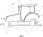
- FIG. 1 illustrates an agricultural machine 1 (hereinafter referred to simply as a tractor) provided with wheels 4, 5 mounted to front and rear axles 2, 3 which are connected to a carrier 9.
- the agricultural machine 1 may be of any other type than a tractor as for example a combine, a forage harvester or a sprayer.
- the agricultural machine 1 has a cabin 8 and a bonnet 12 supported on the carrier 9. Whilst the agricultural machine 1 is illustrated with wheels 4, 5, the agricultural machine 1 can be adapted for use with tracks or other types of driven ground engaging members.
- the term "axle” should be understood as encompassing any suitable arrangement for driving ground engaging members such as wheels or tracks on opposite sides of the agricultural machine 1 for moving it in a driving direction DR.
- a first motor 7 is attached to the carrier 9.
- the first motor 7 is an electric motor.
- a power take-off (PTO) 6 is drivably connected with the first motor 7 for transferring a torque to any tools or implements that may be attached to a linkage 15 of the agricultural machine 1.
- An energy storage 11 is attached to the carrier 9.
- the energy storage 11 can provide electrical energy to the first motor 7 or any other consumer. Additionally, the energy storage 11 may provide chemical energy for example in terms of hydrogen for supplying other components such as a fuel cell.
- the agricultural machine 1 provides a coherent mounting volume 13 extending axially at least partly between the front axle 2 and the rear axle 3.
- the coherent mounting volume 13 may get in contact with the front axle 2 and/or rear axle 3 or may go beyond the front axle 2 and/or the rear axle 3.
- the coherent mounting volume 13 extends beyond the front axle 2 and the rear axle 3.
- the coherent mounting volume 13 may extend beyond only one of the axles 2 and 3.
- the coherent mounting volume 13 can cover a different number of components. As can be seen in FIG. 1 , some components are covered by the coherent mounting volume 13 and some components are arranged outside of the coherent mounting volume 13.
- the first motor 7 and the power take-off 6 are attached to the agricultural machine 1 in such a way that both components are located out of the coherent mounting volume 13. More precisely, the first motor 7 and the power take-off 6 are located behind the coherent mounting volume 13 at the rear side 10 of the agricultural machine 1.
- the upper side of the coherent mounting volume 13 extends to the cabin 8 and gets in contact with a lower part of the cabin 8 at a contact point 14.
- the energy storage 11 is also covered by the coherent mounting volume 13.
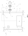
- FIG. 2 shows a schematic representation of a first embodiment of the agricultural machine 1.
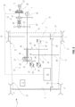
- FIG. 3 shows a schematic representation of a second embodiment of the agricultural machine 1.
- the first and the second embodiment comprise partly the same design as explained in the following in more detail.
- the agricultural machine 1 Opposite to the two left wheels 4 and 5, the agricultural machine 1 comprises two right wheels 17 and 18. Wheel 17 is connected with the front axle 2. Wheel 18 is connected with the rear axle 3. As can be seen in FIG. 2 and FIG. 3 , the coherent mounting volume 13 extends laterally at least partly between the two left wheels 4 and 5 and the two right wheels 17 and 18 and contacts wheel 4 in a contact point 20, wheel 5 in a contact point 21, wheel 17 in a contact point 22 and wheel 18 in a contact point 23.
- the rear axle 3 comprises a differential 19.
- the differential 19 is driveably connected with the first motor 7 so that a torque generated by the first motor 7 can be transferred to the differential 19.
- the first motor 7 can drive the rear axle 3 to move the agricultural machine 1 in the driving direction DR.
- a control unit 32 is connected via a line 24 with the first motor 7 for sending control signals to control the speed and/or the torque of the first motor 7.
- the control unit 32 may control the first motor 7 as a electric generator to generate electrical energy and to charge the energy storage 11.
- the differential 19 as well as the control unit 32 are covered by the coherent mounting volume 13.
- the coherent mounting volume may have the shape of a hexahedron.
- a hexahedron is a polyhedron having six-faces.
- a cube is a specific hexahedron whose faces are shaped as squares.
- the hexahedron may be shaped as a quadrilateral frustum, i. e. an apex-truncated square pyramid.
- FIG. 1 the shape of the left and right side faces of the hexahedron can be seen from a side view.
- FIG. 2 and FIG. 3 show each the shape of a top face and a bottom face of the hexahedron.
- FIG. 5 the shape of a front face and a rear face 16 of the hexahedron can be seen. Additionally, FIG. 1 to FIG. 3 show that the first motor 7 and the power take-off 6 are located behind the rear face 16 of the hexahedron (coherent mounting volume 13).
- the first and the second embodiment of the agricultural machine 1 have the same design. In the following, specific features of the first and the second embodiment of the agricultural machine 1 are described with reference of FIG. 2 and FIG. 3 .
- the first embodiment of the agricultural machine 1 comprises a shaft 25 connecting the differential 19 with the first motor 7.
- a torque generated by the first motor 7 can be transferred to the differential 19 and distributed to the wheels 5 and 18 of the rear axle 3.
- the transfer of the torque via the shaft 25 can be interrupted by a clutch 26 arranged between the differential 19 and the first motor 7.
- a brake 27 is integrated between the differential 19 and the first motor 7 for decelerating the rotational speed of the rear axle 3 and braking the agricultural machine 1.
- the first motor 7 is connected by a shaft 28 with the power take-off 6 to transfer a torque generated by the first motor 7 to the power take-off 6.
- the transfer of torque via the shaft 28 can be interrupted by a clutch 29 arranged between the first motor 7 and the power take-off 6.
- a brake 30 arranged between the first motor 7 and the power take-off 6 can decelerate the rotational speed of the shaft 28 and hold the shaft 28 at a specific position.
- the clutches 26, 29 and the brakes 27 and 30 may be controlled by the control unit 32.
- the clutches 26, 29 may be of any suitable type and may be a friction clutch or a positive engagement clutch, such as a dog clutch.
- the brakes 27 and 30 may be of any suitable type and may be a friction or positive engagement brake.
- the rotational speed of the shaft 28 can be transformed by a PTO transmission 31 arranged between the first motor 7 and the power take-off 6 according to its gear ratio.
- the first motor 7 may drive the shaft 28 at a constant speed of 2500 revolutions per minute (rpm) being transformed to 1000 rpm by the PTO transmission 31 according to a gear ratio of 2,5.
- the clutches 26 and 29 and the brakes 27 and 30 as well as the PTO transmission 31 are arranged outside of the coherent mounting volume 13 and located behind the rear face 16 similar to the first motor 7 and the power take-off 6.
- the coherent mounting volume 13 is free of these components and can be used for an installation of different components between the front axle 2 and the rear axle 3 of the agricultural machine 1 such as the energy storage 11.
- FIG. 3 shows a schematic representation of a second embodiment of the agricultural machine 1 comprising a hydrostatic-mechanical power split transmission 33 with an input shaft 35.
- the hydrostatic-mechanical power split transmission 33 is covered by the coherent mounting volume 13 and comprises a planetary gearset 34 with a fixed gear ratio for providing a mechanical branch and a hydrostatic branch of the hydrostatic-mechanical power split transmission 33.
- the mechanical branch comprises a spur gear 43 with a fixed gear ratio.
- the hydrostatic branch comprises a hydraulic transmission 39 with a variable ratio.
- the hydrostatic branch with variable ratio may also be referred to as a variator.
- the torque transferred via the mechanical and the hydrostatic branch is subsequently summed at a summing shaft 44 upstream of a drive shaft 49.
- the summing shaft 44 is drivingly coupled to drive shaft 49 by a pair of gears 47 and 48 meshing with each other.
- Gear 47 is connected with the summing shaft 44.
- Gear 48 is connected with the drive shaft 49.
- the input shaft 35 is connected with the first motor 7 for providing a torque and drivingly coupled to a planet carrier 36 of the planetary gearset 34 for introducing the torque of the first motor 7.
- the mechanical branch comprising the spur gear 43 is driven by the sun gear 38 the planetary gearset 34.
- the sun gear 38 is drivingly coupled to the summing shaft 44 by a pair of gears 45 and 46 meshing with each other.
- Gear 45 is connected with the sun gear 38.
- Gear 46 is connected with the summing shaft 44.
- the hydraulic transmission 39 of the hydrostatic branch includes a hydraulic pump 41 which is driven by a ring gear 37 of the planetary gearset 34, for example though a pump gear set 40 mechanically connected with the ring gear 37 and the hydraulic pump 41.
- the hydraulic pump 41 is hydraulically connected with a second motor 42 to drive it.
- the second motor 42 is a hydraulic motor providing a torque to the summing shaft 44.
- the hydrostatic branch may have only one hydraulic motor, as indicted by the second motor 42.
- the hydraulic transmission 39 can comprise an additional hydraulic motor as indicated by the third motor 51.
- the third motor 51 may be hydraulically connected with the hydraulic pump 41 and mechanically coupled with the summing shaft 44 via a shaft 50 illustrated in broken line in FIG. 3 .
- a shaft 50 illustrated in broken line in FIG. 3 may be hydraulically connected with the hydraulic pump 41 and mechanically coupled with the summing shaft 44 via a shaft 50 illustrated in broken line in FIG. 3 .
- other configurations for incorporating two hydraulic motors 42, 51 and/or two hydraulic pumps are possible.
- variable displacement hydrostatic unit may be designed as an axial piston swash plate or bent axis unit in which changing the angle of the swash plate or axis alters the displacement.
- This angle will be referred to as the operating angle which can be set by an adjustment unit electronically connected to and regulated by the control unit 32.
- this adjustment unit can be designed as the adjustment unit described in International patent application publication No. WO 2014/096446, published 26 June 2014 , by AGCO International GmbH.
- the control unit 32 is configured to vary the division of power through the mechanical and hydrostatic branches of the hydrostatic-mechanical power split transmission 33 by varying the amount of hydraulic assistance provided by the second (or third) motor 42 (or 51) to propel the agricultural machine 1.
- the overall gear ratio of the hydrostatic-mechanical power split transmission 33 here referred to as the CVT transmission ratio icvr, is the ratio between the rotational speed of the summing shaft 44 and the rotational speed of the input shaft 35.
- the proportion of power transmitted through the hydrostatic branch and hence the CVT transmission ratio i CVT is varied by adjusting the displacements of the hydraulic pump 41 and the second and the optional third motor 42, 51. More details in respect of a hydrostatic-mechanical power split transmission can be found for example in European Patent EP 3 678 892 B1, published 8th June 2022, by AGCO International GmbH .
- the pair of gears 47 and 48 provide a gear reduction and enable the drive shaft 49 to be offset relative to the second motor 42 and the optional third motor 51. However, it may not be necessary to offset the drive shaft 49.
- the pair of gears 47, 48 could be omitted so that the summing shaft 44 forms, or is directly connected with, the drive shaft 49.
- a speed range gear box may be incorporated between the summing shaft 44 and the drive shaft 49.
- the drive shaft 49 is connected with the differential 19 to transfer the torque of the gear 48.
- the differential 19 is drivably connected with the second motor 42 as well as the with the sun gear 38 of the planetary gearset 34.
- the differential 19 distributes the torque to the wheels 5 and 18 of the rear axle 3.
- the torque of the gear 48 can be transferred to an additional differential integrated in the front axle 2 to distribute the torque to the front wheels 4 and 17 and to provide an all-wheel drive of the agricultural machine 1.
- a torque generated by the first motor 7 can be transferred to the power take-off 6.
- the input shaft 35 is also part of a PTO transmission 52 arranged between the first motor 7 and the power take-off 6.
- the PTO transmission 52 is designed as a gearbox comprising two stages having a different gear ratio for transforming the rotational speed of the input shaft 35 to a different rotational speed of the output shaft 53 according to the gear ratio of the corresponding active stage of the PTO transmission 52.
- the first stage comprises a pair of gears 54, 55, the second stage a pair of gears 56, 57.
- Gears 54 and 56 are connected with the input shaft 35.
- Gears 55 and 57 are connected with the output shaft 53.
- a shift collar 58 can be moved between the gear 55 of the first stage and the gear 57 of the second stage to switch between the first stage and the second stage.
- the shift collar 58 is in contact with gear 55, the first stage is active and the speed of the input shaft 35 is transformed according to the first gear ratio.
- the shift collar 58 is in contact with the gear 57, the second stage is active and the speed of the input shaft 35 is transformed according to the second gear ratio.
- two different rotational speeds of the power take-off 6 may be provided, e. g. 540 rpm and 750 rpm.
- the transfer of torque from the output shaft 53 to the power take-off 6 can be interrupted by a clutch 29 arranged between the PTO transmission 52 and the power take-off 6.
- a brake 30 arranged between the PTO transmission 52 and the power take-off 6 can decelerate the rotational speed of the output shaft 53 and hold the output shaft 53 at a specific position.
- the clutch 29, brake 30 and the shift collar 58 may be controlled by the control unit 32.
- the PTO transmission 52, the clutch 29 and the brake 30 are arranged outside of the coherent mounting volume 13 and located behind the rear face 16 similar to the first motor 7 and the power take-off 6.
- the coherent mounting volume 13 is free of these components and can be used for an installation of different components between the front axle 2 and the rear axle 3 of the agricultural machine 1 such as the hydrostatic-mechanical power split transmission 33 and the energy storage 11.
- FIG. 4 and FIG. 5 show a schematic representation for an extended embodiment of the first or the second embodiment of the agricultural machine 1 comprising additionally the energy storage 11.
- FIG. 4 shows a top view of the agricultural machine 1
- FIG. 5 shows a sectional view along the cutting line A-A indicated in FIG. 4 .
- the coherent mounting volume 13 covers the carrier 9 (at least partly).
- the energy storage 11 is mounted to the carrier 9 and is also covered by the coherent mounting volume 13.
- the energy storage 11 is connected with the first motor 7 and optionally with other components to supply energy for these components.
- the energy storage 11 comprises a fuel cell 59 and storage tanks 61, 62, 63 and 64 for storing a fluid such as hydrogen.
- the energy storage 11 may comprise additional components such as a rechargeable battery, power electronics, interfaces for high voltage networks such as an inverter, a brake chopper and a high voltage connector control. Other power electronics components may also be encapsulated within the energy storage 11 as required.
- the energy storage 11 may be connected with the control unit 32 or include a separate controller to regulate the supply of energy to the first motor 7 and to adjust the rotational speed of first motor 7.
- the fuel cell 59 is connected with the storage tanks 61, 62, 63 and 64 to be supplied by the fluid stored in the storage tanks.
- the fuel cell 59 can convert the chemical energy of the fluid into electrical energy.
- the battery is charged by the electrical energy generated by the fuel cell 59 or consumed by any electric consumer.
- the fuel cell 59, the battery and the electric consumers e. g. the first motor 7) are electrically connected by wired to transfer the electrical energy to each other.
- the carrier 9 comprises of longitudinal extending side frames which are connected via transverse connecting parts to form a lead frame enclosing a hallow space 60.
- the storage tanks 61, 62, 63 and 64 thereby extend through cut-outs in the side frames of the carrier 9 to install the storage tanks 61 and 62 over the complete width of the agricultural machine 1, while in the vicinity of the rear wheels 5 and 18, the storage tanks 63 and 64 are be reduced in width to enable an installation between the rear wheels 5 and 18.
- FIG. 6 shows the control unit 32 comprising an interface 65, a controller 66 and a memory 67.
- the control unit 32 may receive and send signals or data via the interface 65.
- the interface 65 may be a wireless interface or a connector.
- the controller 66 may store the data or signals received by the control unit 32 in the memory 67.
- the memory 67 may contain additional data or executable computer program products, for example in terms of a computer-implemented method, that may be retrieved, processed or executed by the controller 66. Data or signals resulting from the processing of data or signals or from the execution of a computer program product may be stored to the memory 67 or sent to the interface 65 by the controller 66.
Landscapes
- Engineering & Computer Science (AREA)
- Chemical & Material Sciences (AREA)
- Combustion & Propulsion (AREA)
- Transportation (AREA)
- Mechanical Engineering (AREA)
- Hybrid Electric Vehicles (AREA)
- Arrangement Or Mounting Of Propulsion Units For Vehicles (AREA)
Abstract
Description
- The present disclosure relates generally to an agricultural machine with an improved mounting volume for electric components.
- Also in the agricultural sector, regulations regarding emissions of vehicles are getting more and more restricted. Manufacturers of agricultural machines try to comply with these restricted regulations by electrifying the drivetrain of the agricultural machines. Thus, electrical components such as electrical energy storages need to be integrated in the agricultural machines for providing an emission free electric drive system. But electrical energy storages for providing electric power to electric drives are often very bulky and therefore require a lot of mounting volume.
- The integration of additional electrical components into an agricultural machine may require a greater mounting volume. Thus, it is an objective to improve the mounting volume of an agricultural machine for integration of additional electric components so that the need of additional mounting volume can be reduced.
- According to an aspect of the invention there is provided an agricultural machine comprising a front axle, a rear axle, a power take-off drivably connected with a first motor and a coherent mounting volume. The coherent mounting volume extends axially at least partly between the front axle and the rear axle. The rear axle comprises a differential. The differential is covered by the coherent mounting volume. The first motor is located out of the coherent mounting volume.
- The agricultural machine may be of any type such as a tractor, a combine, a sprayer or any vehicle combination of a vehicle and an implement or a trailer. The power take-off may be a mechanical interface providing a torque, e. g. for driving an implement connected with the agricultural machine. The torque may be generated by the first motor and transferred to the power take-off. The first motor may be an electric motor. The mounting volume is a coherent mounting volume that may extend in longitudinal direction of the agricultural machine. The torque generated by the first motor may be transferred to the differential. For example, the first motor may comprise a first output for transferring a torque to the differential and a second output for transferring a torque to the power take-off. The first and the second output of the first motor may be oriented in opposite directions. The first and the second output may be part of the same output shaft of the first motor or of two different output shafts of the first motor. The differential may enable to rotate wheels connected to the rear axle at different speeds, e. g. when the agricultural machine is cornering. The coherent mounting volume may enclose the differential to cover it. The coherent mounting volume may extend from the differential in direction to the front axle. The coherent mounting volume may be spaced from the front axle. Alternatively, the coherent mounting volume may reach at least to the front axle to get in contact with the front axle in at least one contact point or may extend beyond the front axle. The more the volume of the coherent mounting volume is increased the more volume can be provided for components to be integrated in the coherent mounting volume.
- Since the first motor is located out of the coherent mounting volume, the volume of the coherent mounting volume is not reduced by the volume of the first motor. Hence, a greater volume of the coherent mounting volume can be provided for other electric components such as bulky electrical energy storages or electrical energy converters such as fuel cells and storage tanks therefor, for example.
- The power take-off may be located out of the coherent mounting volume.
- The power take-off may be directly connected with the first motor by a shaft or indirectly by any type of transmission arranged between the power take-off and the first motor. Since the power take-off is located out of the coherent mounting volume, the volume of the coherent mounting volume is not reduced by the volume of the power take-off.
- The coherent mounting volume may have the shape of a hexahedron.
- A hexahedron is a polyhedron with six faces, i. e. a six-faced solid. The coherent mounting volume may extend along a carrier of the agricultural machine. The carrier may be a support structure for mounting components such as the front or the rear axle, the differential and/or electric components. Due to the shape of a hexahedron, the carrier of the agricultural machine may be at least partly covered by the coherent mounting volume.
- The hexahedron may be a quadrilateral frustum or a rectangular cuboid.
- A quadrilateral frustum is an apex-truncated square pyramid. A rectangular cuboid comprises three pairs of rectangles. I. e. the shape of the coherent mounting volume may be different and may be adapted according to the geometry of the agricultural machine.
- The agricultural machine may comprise left wheels and right wheels. The coherent mounting volume may extend laterally to at least one of the left wheels or the right wheels.
- The coherent mounting volume may extend laterally to one or more wheels of the agricultural machine and may get in contact with the at least one wheel in a contact point. Alternatively, the coherent mounting volume may extend laterally beyond the at least one wheel of the agricultural machine for providing a greater volume of the coherent mounting volume between the front and rear wheels of the agricultural machine. The more the volume of the coherent mounting volume is increased the more volume can be provided for components to be integrated in the coherent mounting volume.
- The agricultural machine may comprise a cabin, wherein the coherent mounting volume may extend at least to the cabin.
- Thus, the volume of the coherent mounting volume may be at least partly limited by the cabin any may get in contact with the cabin in at least one contact point.
- The first motor and the power take-off may be located behind the coherent mounting volume at a rear side of the agricultural machine.
- The carrier of the agricultural machine may extend beyond the rear axle or the differential so that the first motor may be mounted to the carrier of the agricultural machine. If the coherent mounting volume has the shape of a hexahedron, a rear face of the hexahedron may be oriented according to the rear side of the agricultural machine. So, the first motor and the power take-off may be located or mounted behind the rear face of the hexahedron.
- The agricultural machine may comprise a clutch. The clutch may be located out of the coherent mounting volume and configured to interrupt a toque transfer from the first motor to the power take-off.
- The clutch may be arranged between the first motor and the power take-off. Since the clutch is located out of the coherent mounting volume, the volume of the coherent mounting volume is not reduced by the volume of the clutch.
- The coherent mounting volume may extend at least to the rear axle.
- So, the coherent mounting volume may reach at least to the rear axle to get in contact with the rear axle in at least one contact point or may extend beyond the rear axle. The more the volume of the coherent mounting volume is increased the more volume can be provided for components to be integrated in the coherent mounting volume.
- The agricultural machine may comprise an energy storage. The energy storage may be covered by the coherent mounting volume.
- The energy storage may be connected to any electrical component to provide energy to the component, for example to the first motor or to a fuel cell for converting any energy source into electrical energy for the first motor. The coherent mounting volume may enclose the energy storage so that the energy storage is protected by other components covered by the coherent mounting volume against damage or any other external impacts. For example, the energy storage may be hidden or mounted behind the other components covered by the coherent mounting volume for providing a mechanical protection for the energy storage.
- The agricultural machine may comprise a carrier. The carrier may be covered by the coherent mounting volume. The energy storage may be mounted to the carrier.
- The carrier may be the same carrier as mentioned above. The carrier may have a T-shape, a H-shape or any other shape. For example, the carrier may be a two-part carrier comprising two U-shape carrier parts that are welded together. The carrier may comprise at least one hole for inserting and mounting the energy storage.
- The energy storage may comprise at least one storage tank for storing a fluid.
- The fluid may be any fluid such as hydrogen or methanol. The fluid may be provided to the fuel cell to convert the chemical energy of the fluid into electrical energy.
- The energy storage may comprise a battery.
- The battery may store electrical energy. The battery may be connected to the fuel cell to store electrical energy produced by the fuel cell. The battery may be connected to the first motor to provide electrical energy for driving the first motor.
- The agricultural machine may comprise a transmission. The transmission may be covered by the coherent mounting volume. The transmission may be drivably connected with the first motor.
- The transmission may be arranged between the first motor and the differential so that the torque of the first motor can be transferred to the differential via the transmission. The transmission may be of any type such as a planetary gearset, a continuous variable transmission (CVT), a hydrostatic transmission or any combination thereof.
- The transmission may comprise a sun gear, a ring gear, and a planet carrier. The planet carrier may be drivably connected with the first motor.
- The planet carrier holds at least one planet gear rotatably connected with the planet carrier. The at least one planet gear meshes with the sun gear and the ring gear. I. e. the transmission may be designed as a planetary gearset wherein a torque generated by the first motor is transferred to the planet carrier for driving it. Another part of the planetary gearset, as for example the sun gear or the ring gear, may be connected with the differential for transferring the torque to the differential and driving the wheels connected to the differential.
- The transmission may comprise a hydraulic pump drivably connected with the ring gear.
- Thus, the first motor may drive the hydraulic pump for delivering a hydraulic fluid such as oil. The oil may be provided to a hydraulic consumer.
- The transmission may comprise a second motor hydraulically connected with the hydraulic pump. The differential may be drivably connected with the second motor.
- The second motor may be a hydraulic motor driven by the hydraulic fluid delivered by the hydraulic pump. The second motor may generate a torque and transfer the torque to the differential for driving the wheels connected with the differential. Thus, the transmission may be a hydrostatic-mechanical power split transmission for transferring a torque to the differential wherein the torque is generated by the first motor, by the second motor or by both motors.
- The differential may be drivably connected with the sun gear.
- Thus, the differential may be mechanically driven by the first motor transferring a torque to the sun gear via the at least one plant gear rotatably connected with the planet carrier.
- The agricultural machine may comprise a spur gear. The spur gear may be out of the coherent mounting volume. The first motor may be connected with an input shaft of the spur gear. The power take-off may be connected with an output shaft of the spur gear.
- The spur gear may transform the rotational speed of the output of the first motor to a different rotational speed of the power take-off according to a gear ratio of the spur gear. The spur gear may be a switchable spur gear providing multiple gear ratios to switch between the different gear ratios. Since the spur gear is located out of the coherent mounting volume, the volume of the coherent mounting volume is not reduced by the volume of the spur gear.
- The agricultural machine may comprise a control unit. The control unit may be covered by the coherent mounting volume. The control unit may be connected with the first motor.
- The control unit may comprise an inverter and may control the torque or the rotational speed of the first motor. The control unit may be connected to other controllers or sensor units as for example a vehicle controller of the agricultural machine.
- The agricultural machine may comprise a fuel cell. The fuel cell may be covered by the coherent mounting volume. The fuel cell may be connected with the first motor.
- The fuel cell may be a hydrogen fuel cell or a methanol fuel cell. The fuel cell may provide electrical energy to the first motor to drive the first motor. The fuel cell may provide electrical energy to consumers other than the first motor such as the control unit.
- Within the scope of this application it should be understood that the various aspects, embodiments, examples and alternatives set out herein, and individual features thereof may be taken independently or in any possible and compatible combination. Where features are described with reference to a single aspect or embodiment, it should be understood that such features are applicable to all aspects and embodiments unless otherwise stated or where such features are incompatible.
- Several aspects of the invention will now be described, by way of example only, with reference to the accompanying drawings, in which:
-
FIG. 1 illustrates an agricultural machine. -
FIG. 2 illustrates a schematic representation of the agricultural machine in a first embodiment. -
FIG. 3 illustrates a schematic representation of the agricultural machine in a second embodiment. -
FIG. 4 illustrates a schematic representation of the agricultural machine in the first or second embodiment of theagricultural machine 1 comprising additional components. -
FIG. 5 illustrates a sectional view ofFIG. 4 . -
FIG. 6 illustrates a simplified view of a control unit of the agricultural machine. -
FIG. 1 illustrates an agricultural machine 1 (hereinafter referred to simply as a tractor) provided withwheels rear axles carrier 9. Alternatively, theagricultural machine 1 may be of any other type than a tractor as for example a combine, a forage harvester or a sprayer. Theagricultural machine 1 has acabin 8 and abonnet 12 supported on thecarrier 9. Whilst theagricultural machine 1 is illustrated withwheels agricultural machine 1 can be adapted for use with tracks or other types of driven ground engaging members. In this regards, the term "axle" should be understood as encompassing any suitable arrangement for driving ground engaging members such as wheels or tracks on opposite sides of theagricultural machine 1 for moving it in a driving direction DR. At arear side 10 of theagricultural machine 1, afirst motor 7 is attached to thecarrier 9. Thefirst motor 7 is an electric motor. A power take-off (PTO) 6 is drivably connected with thefirst motor 7 for transferring a torque to any tools or implements that may be attached to alinkage 15 of theagricultural machine 1. Anenergy storage 11 is attached to thecarrier 9. Theenergy storage 11 can provide electrical energy to thefirst motor 7 or any other consumer. Additionally, theenergy storage 11 may provide chemical energy for example in terms of hydrogen for supplying other components such as a fuel cell. - The
agricultural machine 1 provides acoherent mounting volume 13 extending axially at least partly between thefront axle 2 and therear axle 3. Thus, the coherent mountingvolume 13 may get in contact with thefront axle 2 and/orrear axle 3 or may go beyond thefront axle 2 and/or therear axle 3. As shown inFIG. 1 , the coherent mountingvolume 13 extends beyond thefront axle 2 and therear axle 3. Alternatively, the coherent mountingvolume 13 may extend beyond only one of theaxles - Depending on the size of the coherent mounting
volume 13, the coherent mountingvolume 13 can cover a different number of components. As can be seen inFIG. 1 , some components are covered by the coherent mountingvolume 13 and some components are arranged outside of the coherent mountingvolume 13. Thefirst motor 7 and the power take-off 6 are attached to theagricultural machine 1 in such a way that both components are located out of the coherent mountingvolume 13. More precisely, thefirst motor 7 and the power take-off 6 are located behind the coherent mountingvolume 13 at therear side 10 of theagricultural machine 1. The upper side of the coherent mountingvolume 13 extends to thecabin 8 and gets in contact with a lower part of thecabin 8 at acontact point 14. Theenergy storage 11 is also covered by the coherent mountingvolume 13. -
FIG. 2 shows a schematic representation of a first embodiment of theagricultural machine 1.FIG. 3 shows a schematic representation of a second embodiment of theagricultural machine 1. As can be seen inFIG. 2 andFIG. 3 , the first and the second embodiment comprise partly the same design as explained in the following in more detail. - Opposite to the two
left wheels agricultural machine 1 comprises tworight wheels Wheel 17 is connected with thefront axle 2.Wheel 18 is connected with therear axle 3. As can be seen inFIG. 2 andFIG. 3 , the coherent mountingvolume 13 extends laterally at least partly between the twoleft wheels right wheels contact point 20,wheel 5 in acontact point 21,wheel 17 in acontact point 22 andwheel 18 in acontact point 23. - The
rear axle 3 comprises a differential 19. The differential 19 is driveably connected with thefirst motor 7 so that a torque generated by thefirst motor 7 can be transferred to the differential 19. Thus, thefirst motor 7 can drive therear axle 3 to move theagricultural machine 1 in the driving direction DR. Acontrol unit 32 is connected via aline 24 with thefirst motor 7 for sending control signals to control the speed and/or the torque of thefirst motor 7. Thecontrol unit 32 may control thefirst motor 7 as a electric generator to generate electrical energy and to charge theenergy storage 11. The differential 19 as well as thecontrol unit 32 are covered by the coherent mountingvolume 13. - The coherent mounting volume may have the shape of a hexahedron. In geometry, a hexahedron is a polyhedron having six-faces. For example, a cube is a specific hexahedron whose faces are shaped as squares. Alternatively, the hexahedron may be shaped as a quadrilateral frustum, i. e. an apex-truncated square pyramid. In
FIG. 1 , the shape of the left and right side faces of the hexahedron can be seen from a side view.FIG. 2 andFIG. 3 show each the shape of a top face and a bottom face of the hexahedron. InFIG. 5 , the shape of a front face and arear face 16 of the hexahedron can be seen. Additionally,FIG. 1 to FIG. 3 show that thefirst motor 7 and the power take-off 6 are located behind therear face 16 of the hexahedron (coherent mounting volume 13). - So far, the first and the second embodiment of the
agricultural machine 1 have the same design. In the following, specific features of the first and the second embodiment of theagricultural machine 1 are described with reference ofFIG. 2 andFIG. 3 . - As can be seen in
FIG. 2 , the first embodiment of theagricultural machine 1 comprises ashaft 25 connecting the differential 19 with thefirst motor 7. Hence, a torque generated by thefirst motor 7 can be transferred to the differential 19 and distributed to thewheels rear axle 3. The transfer of the torque via theshaft 25 can be interrupted by a clutch 26 arranged between the differential 19 and thefirst motor 7. In addition, abrake 27 is integrated between the differential 19 and thefirst motor 7 for decelerating the rotational speed of therear axle 3 and braking theagricultural machine 1. Next to the differential 19, thefirst motor 7 is connected by ashaft 28 with the power take-off 6 to transfer a torque generated by thefirst motor 7 to the power take-off 6. The transfer of torque via theshaft 28 can be interrupted by a clutch 29 arranged between thefirst motor 7 and the power take-off 6. Abrake 30 arranged between thefirst motor 7 and the power take-off 6 can decelerate the rotational speed of theshaft 28 and hold theshaft 28 at a specific position. Theclutches brakes control unit 32. Theclutches brakes shaft 28 can be transformed by aPTO transmission 31 arranged between thefirst motor 7 and the power take-off 6 according to its gear ratio. For example, thefirst motor 7 may drive theshaft 28 at a constant speed of 2500 revolutions per minute (rpm) being transformed to 1000 rpm by thePTO transmission 31 according to a gear ratio of 2,5. - The
clutches brakes PTO transmission 31 are arranged outside of the coherent mountingvolume 13 and located behind therear face 16 similar to thefirst motor 7 and the power take-off 6. Thus, the coherent mountingvolume 13 is free of these components and can be used for an installation of different components between thefront axle 2 and therear axle 3 of theagricultural machine 1 such as theenergy storage 11. -
FIG. 3 shows a schematic representation of a second embodiment of theagricultural machine 1 comprising a hydrostatic-mechanicalpower split transmission 33 with aninput shaft 35. The hydrostatic-mechanicalpower split transmission 33 is covered by the coherent mountingvolume 13 and comprises aplanetary gearset 34 with a fixed gear ratio for providing a mechanical branch and a hydrostatic branch of the hydrostatic-mechanicalpower split transmission 33. The mechanical branch comprises aspur gear 43 with a fixed gear ratio. The hydrostatic branch comprises a hydraulic transmission 39 with a variable ratio. The hydrostatic branch with variable ratio may also be referred to as a variator. The torque transferred via the mechanical and the hydrostatic branch is subsequently summed at a summingshaft 44 upstream of adrive shaft 49. The summingshaft 44 is drivingly coupled to driveshaft 49 by a pair ofgears Gear 47 is connected with the summingshaft 44.Gear 48 is connected with thedrive shaft 49. - The
input shaft 35 is connected with thefirst motor 7 for providing a torque and drivingly coupled to aplanet carrier 36 of theplanetary gearset 34 for introducing the torque of thefirst motor 7. The mechanical branch comprising thespur gear 43 is driven by thesun gear 38 theplanetary gearset 34. As illustrated inFIG. 3 , thesun gear 38 is drivingly coupled to the summingshaft 44 by a pair ofgears Gear 45 is connected with thesun gear 38.Gear 46 is connected with the summingshaft 44. - The hydraulic transmission 39 of the hydrostatic branch includes a
hydraulic pump 41 which is driven by aring gear 37 of theplanetary gearset 34, for example though a pump gear set 40 mechanically connected with thering gear 37 and thehydraulic pump 41. Thehydraulic pump 41 is hydraulically connected with asecond motor 42 to drive it. Thesecond motor 42 is a hydraulic motor providing a torque to the summingshaft 44. For low specification transmissions commonly used for low horse power applications, the hydrostatic branch may have only one hydraulic motor, as indicted by thesecond motor 42. However, for high horse power applications, the hydraulic transmission 39 can comprise an additional hydraulic motor as indicated by thethird motor 51. Thethird motor 51 may be hydraulically connected with thehydraulic pump 41 and mechanically coupled with the summingshaft 44 via ashaft 50 illustrated in broken line inFIG. 3 . However, other configurations for incorporating twohydraulic motors - The
hydraulic pump 41 and the second andthird motors control unit 32. For example, this adjustment unit can be designed as the adjustment unit described in International patent application publication No.WO 2014/096446, published 26 June 2014 , by AGCO International GmbH. Thecontrol unit 32 is configured to vary the division of power through the mechanical and hydrostatic branches of the hydrostatic-mechanicalpower split transmission 33 by varying the amount of hydraulic assistance provided by the second (or third) motor 42 (or 51) to propel theagricultural machine 1. The overall gear ratio of the hydrostatic-mechanicalpower split transmission 33, here referred to as the CVT transmission ratio icvr, is the ratio between the rotational speed of the summingshaft 44 and the rotational speed of theinput shaft 35. When power is transmitted through both the mechanical branch and the hydrostatic branch, the CVT transmission ratio iCVT is continuously variable depending on what proportion of the power is transmitted through the hydrostatic branch. The proportion of power transmitted through the hydrostatic branch and hence the CVT transmission ratio iCVT is varied by adjusting the displacements of thehydraulic pump 41 and the second and the optionalthird motor European Patent EP 3 678 892 B1, published 8th June 2022, by AGCO International GmbH . - The pair of
gears drive shaft 49 to be offset relative to thesecond motor 42 and the optionalthird motor 51. However, it may not be necessary to offset thedrive shaft 49. The pair ofgears shaft 44 forms, or is directly connected with, thedrive shaft 49. Optionally, a speed range gear box may be incorporated between the summingshaft 44 and thedrive shaft 49. - The
drive shaft 49 is connected with the differential 19 to transfer the torque of thegear 48. Hence, the differential 19 is drivably connected with thesecond motor 42 as well as the with thesun gear 38 of theplanetary gearset 34. Analogously to the first embodiment according toFIG. 2 , the differential 19 distributes the torque to thewheels rear axle 3. Optionally, the torque of thegear 48 can be transferred to an additional differential integrated in thefront axle 2 to distribute the torque to thefront wheels agricultural machine 1. - Analogous to the first embodiment of
FIG. 2 , a torque generated by thefirst motor 7 can be transferred to the power take-off 6. Theinput shaft 35 is also part of aPTO transmission 52 arranged between thefirst motor 7 and the power take-off 6. ThePTO transmission 52 is designed as a gearbox comprising two stages having a different gear ratio for transforming the rotational speed of theinput shaft 35 to a different rotational speed of theoutput shaft 53 according to the gear ratio of the corresponding active stage of thePTO transmission 52. The first stage comprises a pair ofgears gears Gears input shaft 35.Gears output shaft 53. Ashift collar 58 can be moved between thegear 55 of the first stage and thegear 57 of the second stage to switch between the first stage and the second stage. When theshift collar 58 is in contact withgear 55, the first stage is active and the speed of theinput shaft 35 is transformed according to the first gear ratio. When theshift collar 58 is in contact with thegear 57, the second stage is active and the speed of theinput shaft 35 is transformed according to the second gear ratio. Thus, two different rotational speeds of the power take-off 6 may be provided, e. g. 540 rpm and 750 rpm. The transfer of torque from theoutput shaft 53 to the power take-off 6 can be interrupted by a clutch 29 arranged between thePTO transmission 52 and the power take-off 6. Abrake 30 arranged between thePTO transmission 52 and the power take-off 6 can decelerate the rotational speed of theoutput shaft 53 and hold theoutput shaft 53 at a specific position. The clutch 29,brake 30 and theshift collar 58 may be controlled by thecontrol unit 32. - The
PTO transmission 52, the clutch 29 and thebrake 30 are arranged outside of the coherent mountingvolume 13 and located behind therear face 16 similar to thefirst motor 7 and the power take-off 6. Thus, the coherent mountingvolume 13 is free of these components and can be used for an installation of different components between thefront axle 2 and therear axle 3 of theagricultural machine 1 such as the hydrostatic-mechanicalpower split transmission 33 and theenergy storage 11. -
FIG. 4 and FIG. 5 show a schematic representation for an extended embodiment of the first or the second embodiment of theagricultural machine 1 comprising additionally theenergy storage 11.FIG. 4 shows a top view of theagricultural machine 1 andFIG. 5 shows a sectional view along the cutting line A-A indicated inFIG. 4 . Since thefirst motor 7, thePTO transmission off 6 are arranged at therear face 16 outside the coherent mountingvolume 13, the coherent mountingvolume 13 provides free space between thefront axle 2 and therear axle 3 for installing theenergy storage 11. Thecoherent mounting volume 13 covers the carrier 9 (at least partly). Theenergy storage 11 is mounted to thecarrier 9 and is also covered by the coherent mountingvolume 13. Theenergy storage 11 is connected with thefirst motor 7 and optionally with other components to supply energy for these components. - The
energy storage 11 comprises afuel cell 59 andstorage tanks energy storage 11 may comprise additional components such as a rechargeable battery, power electronics, interfaces for high voltage networks such as an inverter, a brake chopper and a high voltage connector control. Other power electronics components may also be encapsulated within theenergy storage 11 as required. Theenergy storage 11 may be connected with thecontrol unit 32 or include a separate controller to regulate the supply of energy to thefirst motor 7 and to adjust the rotational speed offirst motor 7. Thefuel cell 59 is connected with thestorage tanks fuel cell 59 can convert the chemical energy of the fluid into electrical energy. Then, the battery is charged by the electrical energy generated by thefuel cell 59 or consumed by any electric consumer. Thefuel cell 59, the battery and the electric consumers (e. g. the first motor 7) are electrically connected by wired to transfer the electrical energy to each other. - As can be seen in
FIG. 4 and FIG. 5 , thecarrier 9 comprises of longitudinal extending side frames which are connected via transverse connecting parts to form a lead frame enclosing ahallow space 60. Thestorage tanks carrier 9 to install thestorage tanks agricultural machine 1, while in the vicinity of therear wheels storage tanks rear wheels -
FIG. 6 shows thecontrol unit 32 comprising aninterface 65, acontroller 66 and amemory 67. Thecontrol unit 32 may receive and send signals or data via theinterface 65. Theinterface 65 may be a wireless interface or a connector. Thecontroller 66 may store the data or signals received by thecontrol unit 32 in thememory 67. Thememory 67 may contain additional data or executable computer program products, for example in terms of a computer-implemented method, that may be retrieved, processed or executed by thecontroller 66. Data or signals resulting from the processing of data or signals or from the execution of a computer program product may be stored to thememory 67 or sent to theinterface 65 by thecontroller 66. - All references cited herein are incorporated herein in their entireties. If there is a conflict between definitions herein and in an incorporated reference, the definition herein shall control.
-
1 agricultural machine 19 differential 2 front axle 20 contact point 3 rear axle 21 contact point 4 wheel 22 contact point 5 wheel 23 contact point 6 power take- off 24 line 7 first motor 25 shaft 8 cabin 26 clutch 9 carrier 27 brake 10 rear side 28 shaft 11 energy storage 29 clutch 12 bonnet 30 brake 13 coherent mounting volume 31 PTO transmission 14 contact point 32 control unit 15 linkage 33 transmission 16 rear face 34 planetary gearset 17 wheel 35 input shaft 18 wheel 36 planet carrier 37 ring gear 60 hallow space 38 sun gear 61 storage tank 39 hydraulic transmission 62 storage tank 40 pump gear set 63 storage tank 41 hydraulic pump 64 storage tank 42 second motor 65 interface 43 spur gear 66 controller 44 summing shaft 67 memory 45 gear 46 gear 47 gear 48 gear 49 drive shaft 50 shaft 51 third motor 52 PTO transmission 53 output shaft 54 gear 55 gear 56 gear 57 gear 58 shift collar 59 fuel cell
Claims (16)
- An agricultural machine (1), comprising:a front axle (2);a rear axle (3);a power take-off (6) drivably connected with a first motor (7); anda coherent mounting volume (13);whereinthe coherent mounting volume (13) extends axially at least partly between the front axle (2) and the rear axle (3); and whereinthe rear axle (3) comprises a differential (19);the differential (19) is covered by the coherent mounting volume (13); andthe first motor (7) is located out of the coherent mounting volume (13).
- The agricultural machine (1) of claim 1, wherein the coherent mounting volume (13) has the shape of a hexahedron.
- The agricultural machine (1) of claim 2, wherein the hexahedron is a quadrilateral frustum or a rectangular cuboid.
- The agricultural machine (1) of any one of the preceding claims, wherein the power take-off (6) is located out of the coherent mounting volume (13).
- The agricultural machine (1) of any one of the preceding claims, comprising left wheels (4, 5);right wheels (17, 18); whereinthe coherent mounting volume (13) extends laterally to at least one of the left wheels (4, 5) or the right wheels (17, 18).
- The agricultural machine (1) of any one of the preceding claims, comprising a cabin (8); wherein
the coherent mounting volume (13) extents at least to the cabin (8). - The agricultural machine (1) of any one of the preceding claims, wherein
the first motor (7) and the power take-off (6) are located behind the coherent mounting volume (13) at a rear side (10) of the agricultural machine (1). - The agricultural machine (1) of any one of the preceding claims, comprising a clutch (26, 29); wherein
the clutch (26, 29) is located out of the coherent mounting volume (13) and configured to interrupt a toque transfer from the first motor (7) to the power take-off (6). - The agricultural machine (1) of any one of the preceding claims, wherein
the coherent mounting volume (13) extends at least to the rear axle (3). - The agricultural machine (1) of any one of the preceding claims, comprising an energy storage (11); wherein
the energy storage (11) is covered by the coherent mounting volume (13). - The agricultural machine (1) of claim 10, comprisinga carrier (9); whereinthe carrier (9) is covered by the coherent mounting volume (13); andthe energy storage (11) is mounted to the carrier (9).
- The agricultural machine (1) of claim 10 or 11, wherein
the energy storage (11) comprises at least one storage tank (61, 62, 63, 64) for storing a fluid. - The agricultural machine (1) of any one of the preceding claims, comprising a transmission (33); whereinthe transmission (33) is covered by the coherent mounting volume (13); andthe transmission (33) is drivably connected with the first motor (7).
- The agricultural machine (1) of any one of the preceding claims, comprising a PTO transmission (31, 52); whereinthe PTO transmission (31, 52) is out of the coherent mounting volume (13);the first motor (7) is connected with a shaft (28, 35) of the PTO transmission (31, 52); andthe power take-off (6) is connected with a shaft (53) of the PTO transmission (31, 52).
- The agricultural machine (1) of any one of the preceding claims, comprising a control unit (32); whereinthe control unit (32) is covered by the coherent mounting volume (13); andthe control unit (32) is connected with the first motor (7).
- The agricultural machine (1) of any one of the preceding claims, comprising a fuel cell (59); whereinthe fuel cell (59) is covered by the coherent mounting volume (13); andthe fuel cell (59) is connected with the first motor (7).
Applications Claiming Priority (1)
| Application Number | Priority Date | Filing Date | Title |
|---|---|---|---|
| GBGB2310333.6A GB202310333D0 (en) | 2023-07-05 | 2023-07-05 | Agricultural machine with improved mounting volume |
Publications (1)
| Publication Number | Publication Date |
|---|---|
| EP4488094A1 true EP4488094A1 (en) | 2025-01-08 |
Family
ID=87556711
Family Applications (1)
| Application Number | Title | Priority Date | Filing Date |
|---|---|---|---|
| EP24181642.0A Withdrawn EP4488094A1 (en) | 2023-07-05 | 2024-06-12 | Agricultural machine with improved mounting volume |
Country Status (3)
| Country | Link |
|---|---|
| US (1) | US20250010707A1 (en) |
| EP (1) | EP4488094A1 (en) |
| GB (1) | GB202310333D0 (en) |
Citations (9)
| Publication number | Priority date | Publication date | Assignee | Title |
|---|---|---|---|---|
| US4040497A (en) * | 1975-08-11 | 1977-08-09 | Tri Tractor Manufacturing Co., Inc. | Tractor |
| JPH0586770U (en) * | 1992-04-30 | 1993-11-22 | 三菱農機株式会社 | Electric agricultural tractor |
| JP4815703B2 (en) * | 2001-07-02 | 2011-11-16 | 井関農機株式会社 | Tractor |
| WO2014096446A1 (en) | 2012-12-21 | 2014-06-26 | Agco International Gmbh | Control mechanism for a continuously variable transmission |
| US9989986B2 (en) * | 2013-03-12 | 2018-06-05 | Cnh Industrial America Llc | Hitch position encoder with reference indicator for agricultural work vehicle |
| EP3678892B1 (en) | 2017-09-05 | 2022-06-08 | AGCO International GmbH | Agricultural vehicle having electrical drive line |
| EP4029711A1 (en) * | 2021-01-14 | 2022-07-20 | CNH Industrial Italia S.p.A. | Front hybrid driving axle for an agricultural vehicle |
| US11492780B1 (en) * | 2021-10-26 | 2022-11-08 | Deere & Company | Work vehicle having electric machine and energy storage device |
| WO2023022467A1 (en) * | 2021-08-20 | 2023-02-23 | 충남대학교산학협력단 | Hydrogen fuel cell tractor |
-
2023
- 2023-07-05 GB GBGB2310333.6A patent/GB202310333D0/en not_active Ceased
-
2024
- 2024-06-12 EP EP24181642.0A patent/EP4488094A1/en not_active Withdrawn
- 2024-06-12 US US18/741,517 patent/US20250010707A1/en active Pending
Patent Citations (9)
| Publication number | Priority date | Publication date | Assignee | Title |
|---|---|---|---|---|
| US4040497A (en) * | 1975-08-11 | 1977-08-09 | Tri Tractor Manufacturing Co., Inc. | Tractor |
| JPH0586770U (en) * | 1992-04-30 | 1993-11-22 | 三菱農機株式会社 | Electric agricultural tractor |
| JP4815703B2 (en) * | 2001-07-02 | 2011-11-16 | 井関農機株式会社 | Tractor |
| WO2014096446A1 (en) | 2012-12-21 | 2014-06-26 | Agco International Gmbh | Control mechanism for a continuously variable transmission |
| US9989986B2 (en) * | 2013-03-12 | 2018-06-05 | Cnh Industrial America Llc | Hitch position encoder with reference indicator for agricultural work vehicle |
| EP3678892B1 (en) | 2017-09-05 | 2022-06-08 | AGCO International GmbH | Agricultural vehicle having electrical drive line |
| EP4029711A1 (en) * | 2021-01-14 | 2022-07-20 | CNH Industrial Italia S.p.A. | Front hybrid driving axle for an agricultural vehicle |
| WO2023022467A1 (en) * | 2021-08-20 | 2023-02-23 | 충남대학교산학협력단 | Hydrogen fuel cell tractor |
| US11492780B1 (en) * | 2021-10-26 | 2022-11-08 | Deere & Company | Work vehicle having electric machine and energy storage device |
Also Published As
| Publication number | Publication date |
|---|---|
| GB202310333D0 (en) | 2023-08-16 |
| US20250010707A1 (en) | 2025-01-09 |
Similar Documents
| Publication | Publication Date | Title |
|---|---|---|
| EP3863876B1 (en) | Electric utility vehicle driveline recharging | |
| EP3863877B1 (en) | Utility vehicle driveline | |
| EP1199204B1 (en) | Hybrid propulsion unit for a tractor | |
| US11137052B2 (en) | Transmission assembly with integrated CVP | |
| CN107878192B (en) | Electrohydraulic drive device for work vehicle | |
| US10190662B2 (en) | Variator for work vehicle drivetrain | |
| US11845337B2 (en) | Electric hybrid transmission architecture for a work vehicle | |
| EP2566716B1 (en) | Tractor with hybrid power system | |
| CN107627840B (en) | Transmission for a work vehicle drive train | |
| US9695920B2 (en) | Agricultural vehicle transmission | |
| GB2493961A (en) | Power takeoff drive system for an agricultural tractor | |
| EP1707418B1 (en) | Hybrid-type forklift | |
| US11333236B2 (en) | Drivetrain system having an axle assembly | |
| US20250010707A1 (en) | Agricultural Machine with Improved Mounting Volume | |
| US20190113110A1 (en) | Infinitely variable power transmission system | |
| WO2024121634A1 (en) | Vehicle powertrain, method and vehicle | |
| WO2019208819A1 (en) | Working machine | |
| CN224130872U (en) | CVT power assembly of efficient tractor | |
| WO2014096450A1 (en) | Agricultural vehicle transmission | |
| CN222061733U (en) | Tractor and drive system thereof | |
| CN223086136U (en) | Hybrid power agricultural caterpillar track traveling system | |
| EP4389486A1 (en) | Vehicle | |
| US20250340106A1 (en) | Hybrid electric variable transmission for all-wheel drive off-road capable vehicle | |
| WO2024121635A1 (en) | Vehicle powertrain, method and vehicle | |
| WO2014096451A1 (en) | Vehicle transmission |
Legal Events
| Date | Code | Title | Description |
|---|---|---|---|
| PUAI | Public reference made under article 153(3) epc to a published international application that has entered the european phase |
Free format text: ORIGINAL CODE: 0009012 |
|
| STAA | Information on the status of an ep patent application or granted ep patent |
Free format text: STATUS: THE APPLICATION HAS BEEN PUBLISHED |
|
| AK | Designated contracting states |
Kind code of ref document: A1 Designated state(s): AL AT BE BG CH CY CZ DE DK EE ES FI FR GB GR HR HU IE IS IT LI LT LU LV MC ME MK MT NL NO PL PT RO RS SE SI SK SM TR |
|
| STAA | Information on the status of an ep patent application or granted ep patent |
Free format text: STATUS: REQUEST FOR EXAMINATION WAS MADE |
|
| 17P | Request for examination filed |
Effective date: 20250708 |
|
| STAA | Information on the status of an ep patent application or granted ep patent |
Free format text: STATUS: THE APPLICATION IS DEEMED TO BE WITHDRAWN |
|
| 18D | Application deemed to be withdrawn |
Effective date: 20250709 |