EP4488089A1 - Cabin structure of vehicle and method of manufacturing a vehicle - Google Patents
Cabin structure of vehicle and method of manufacturing a vehicle Download PDFInfo
- Publication number
- EP4488089A1 EP4488089A1 EP24183912.5A EP24183912A EP4488089A1 EP 4488089 A1 EP4488089 A1 EP 4488089A1 EP 24183912 A EP24183912 A EP 24183912A EP 4488089 A1 EP4488089 A1 EP 4488089A1
- Authority
- EP
- European Patent Office
- Prior art keywords
- vehicle
- battery
- floor
- seat
- seats
- Prior art date
- Legal status (The legal status is an assumption and is not a legal conclusion. Google has not performed a legal analysis and makes no representation as to the accuracy of the status listed.)
- Granted
Links
Images








Classifications
-
- B—PERFORMING OPERATIONS; TRANSPORTING
- B60—VEHICLES IN GENERAL
- B60K—ARRANGEMENT OR MOUNTING OF PROPULSION UNITS OR OF TRANSMISSIONS IN VEHICLES; ARRANGEMENT OR MOUNTING OF PLURAL DIVERSE PRIME-MOVERS IN VEHICLES; AUXILIARY DRIVES FOR VEHICLES; INSTRUMENTATION OR DASHBOARDS FOR VEHICLES; ARRANGEMENTS IN CONNECTION WITH COOLING, AIR INTAKE, GAS EXHAUST OR FUEL SUPPLY OF PROPULSION UNITS IN VEHICLES
- B60K1/00—Arrangement or mounting of electrical propulsion units
- B60K1/04—Arrangement or mounting of electrical propulsion units of the electric storage means for propulsion
-
- B—PERFORMING OPERATIONS; TRANSPORTING
- B60—VEHICLES IN GENERAL
- B60H—ARRANGEMENTS OF HEATING, COOLING, VENTILATING OR OTHER AIR-TREATING DEVICES SPECIALLY ADAPTED FOR PASSENGER OR GOODS SPACES OF VEHICLES
- B60H1/00—Heating, cooling or ventilating devices
- B60H1/00007—Combined heating, ventilating, or cooling devices
- B60H1/00021—Air flow details of HVAC devices
- B60H1/00028—Constructional lay-out of the devices in the vehicle
-
- B—PERFORMING OPERATIONS; TRANSPORTING
- B60—VEHICLES IN GENERAL
- B60N—SEATS SPECIALLY ADAPTED FOR VEHICLES; VEHICLE PASSENGER ACCOMMODATION NOT OTHERWISE PROVIDED FOR
- B60N2/00—Seats specially adapted for vehicles; Arrangement or mounting of seats in vehicles
- B60N2/02—Seats specially adapted for vehicles; Arrangement or mounting of seats in vehicles the seat or part thereof being movable, e.g. adjustable
- B60N2/20—Seats specially adapted for vehicles; Arrangement or mounting of seats in vehicles the seat or part thereof being movable, e.g. adjustable the back-rest being tiltable, e.g. to permit easy access
-
- B—PERFORMING OPERATIONS; TRANSPORTING
- B60—VEHICLES IN GENERAL
- B60R—VEHICLES, VEHICLE FITTINGS, OR VEHICLE PARTS, NOT OTHERWISE PROVIDED FOR
- B60R5/00—Compartments within vehicle body primarily intended or sufficiently spacious for trunks, suit-cases, or the like
-
- B—PERFORMING OPERATIONS; TRANSPORTING
- B60—VEHICLES IN GENERAL
- B60R—VEHICLES, VEHICLE FITTINGS, OR VEHICLE PARTS, NOT OTHERWISE PROVIDED FOR
- B60R7/00—Stowing or holding appliances inside vehicle primarily intended for personal property smaller than suit-cases, e.g. travelling articles, or maps
- B60R7/04—Stowing or holding appliances inside vehicle primarily intended for personal property smaller than suit-cases, e.g. travelling articles, or maps in driver or passenger space, e.g. using racks
-
- B—PERFORMING OPERATIONS; TRANSPORTING
- B62—LAND VEHICLES FOR TRAVELLING OTHERWISE THAN ON RAILS
- B62D—MOTOR VEHICLES; TRAILERS
- B62D25/00—Superstructure or monocoque structure sub-units; Parts or details thereof not otherwise provided for
-
- B—PERFORMING OPERATIONS; TRANSPORTING
- B62—LAND VEHICLES FOR TRAVELLING OTHERWISE THAN ON RAILS
- B62D—MOTOR VEHICLES; TRAILERS
- B62D25/00—Superstructure or monocoque structure sub-units; Parts or details thereof not otherwise provided for
- B62D25/08—Front or rear portions
- B62D25/088—Details of structures as upper supports for springs or dampers
-
- B—PERFORMING OPERATIONS; TRANSPORTING
- B62—LAND VEHICLES FOR TRAVELLING OTHERWISE THAN ON RAILS
- B62D—MOTOR VEHICLES; TRAILERS
- B62D25/00—Superstructure or monocoque structure sub-units; Parts or details thereof not otherwise provided for
- B62D25/20—Floors or bottom sub-units
-
- B—PERFORMING OPERATIONS; TRANSPORTING
- B60—VEHICLES IN GENERAL
- B60H—ARRANGEMENTS OF HEATING, COOLING, VENTILATING OR OTHER AIR-TREATING DEVICES SPECIALLY ADAPTED FOR PASSENGER OR GOODS SPACES OF VEHICLES
- B60H1/00—Heating, cooling or ventilating devices
- B60H1/00007—Combined heating, ventilating, or cooling devices
- B60H1/00021—Air flow details of HVAC devices
- B60H2001/00185—Distribution of conditionned air
- B60H2001/002—Distribution of conditionned air to front and rear part of passenger compartment
-
- B—PERFORMING OPERATIONS; TRANSPORTING
- B60—VEHICLES IN GENERAL
- B60K—ARRANGEMENT OR MOUNTING OF PROPULSION UNITS OR OF TRANSMISSIONS IN VEHICLES; ARRANGEMENT OR MOUNTING OF PLURAL DIVERSE PRIME-MOVERS IN VEHICLES; AUXILIARY DRIVES FOR VEHICLES; INSTRUMENTATION OR DASHBOARDS FOR VEHICLES; ARRANGEMENTS IN CONNECTION WITH COOLING, AIR INTAKE, GAS EXHAUST OR FUEL SUPPLY OF PROPULSION UNITS IN VEHICLES
- B60K1/00—Arrangement or mounting of electrical propulsion units
- B60K1/04—Arrangement or mounting of electrical propulsion units of the electric storage means for propulsion
- B60K2001/0405—Arrangement or mounting of electrical propulsion units of the electric storage means for propulsion characterised by their position
-
- B—PERFORMING OPERATIONS; TRANSPORTING
- B60—VEHICLES IN GENERAL
- B60K—ARRANGEMENT OR MOUNTING OF PROPULSION UNITS OR OF TRANSMISSIONS IN VEHICLES; ARRANGEMENT OR MOUNTING OF PLURAL DIVERSE PRIME-MOVERS IN VEHICLES; AUXILIARY DRIVES FOR VEHICLES; INSTRUMENTATION OR DASHBOARDS FOR VEHICLES; ARRANGEMENTS IN CONNECTION WITH COOLING, AIR INTAKE, GAS EXHAUST OR FUEL SUPPLY OF PROPULSION UNITS IN VEHICLES
- B60K1/00—Arrangement or mounting of electrical propulsion units
- B60K1/04—Arrangement or mounting of electrical propulsion units of the electric storage means for propulsion
- B60K2001/0405—Arrangement or mounting of electrical propulsion units of the electric storage means for propulsion characterised by their position
- B60K2001/0411—Arrangement in the front part of the vehicle
-
- B—PERFORMING OPERATIONS; TRANSPORTING
- B60—VEHICLES IN GENERAL
- B60K—ARRANGEMENT OR MOUNTING OF PROPULSION UNITS OR OF TRANSMISSIONS IN VEHICLES; ARRANGEMENT OR MOUNTING OF PLURAL DIVERSE PRIME-MOVERS IN VEHICLES; AUXILIARY DRIVES FOR VEHICLES; INSTRUMENTATION OR DASHBOARDS FOR VEHICLES; ARRANGEMENTS IN CONNECTION WITH COOLING, AIR INTAKE, GAS EXHAUST OR FUEL SUPPLY OF PROPULSION UNITS IN VEHICLES
- B60K1/00—Arrangement or mounting of electrical propulsion units
- B60K1/04—Arrangement or mounting of electrical propulsion units of the electric storage means for propulsion
- B60K2001/0405—Arrangement or mounting of electrical propulsion units of the electric storage means for propulsion characterised by their position
- B60K2001/0416—Arrangement in the rear part of the vehicle
-
- B—PERFORMING OPERATIONS; TRANSPORTING
- B60—VEHICLES IN GENERAL
- B60K—ARRANGEMENT OR MOUNTING OF PROPULSION UNITS OR OF TRANSMISSIONS IN VEHICLES; ARRANGEMENT OR MOUNTING OF PLURAL DIVERSE PRIME-MOVERS IN VEHICLES; AUXILIARY DRIVES FOR VEHICLES; INSTRUMENTATION OR DASHBOARDS FOR VEHICLES; ARRANGEMENTS IN CONNECTION WITH COOLING, AIR INTAKE, GAS EXHAUST OR FUEL SUPPLY OF PROPULSION UNITS IN VEHICLES
- B60K1/00—Arrangement or mounting of electrical propulsion units
- B60K1/04—Arrangement or mounting of electrical propulsion units of the electric storage means for propulsion
- B60K2001/0405—Arrangement or mounting of electrical propulsion units of the electric storage means for propulsion characterised by their position
- B60K2001/0427—Arrangement between the seats
-
- B—PERFORMING OPERATIONS; TRANSPORTING
- B60—VEHICLES IN GENERAL
- B60K—ARRANGEMENT OR MOUNTING OF PROPULSION UNITS OR OF TRANSMISSIONS IN VEHICLES; ARRANGEMENT OR MOUNTING OF PLURAL DIVERSE PRIME-MOVERS IN VEHICLES; AUXILIARY DRIVES FOR VEHICLES; INSTRUMENTATION OR DASHBOARDS FOR VEHICLES; ARRANGEMENTS IN CONNECTION WITH COOLING, AIR INTAKE, GAS EXHAUST OR FUEL SUPPLY OF PROPULSION UNITS IN VEHICLES
- B60K1/00—Arrangement or mounting of electrical propulsion units
- B60K1/04—Arrangement or mounting of electrical propulsion units of the electric storage means for propulsion
- B60K2001/0405—Arrangement or mounting of electrical propulsion units of the electric storage means for propulsion characterised by their position
- B60K2001/0438—Arrangement under the floor
-
- B—PERFORMING OPERATIONS; TRANSPORTING
- B60—VEHICLES IN GENERAL
- B60Y—INDEXING SCHEME RELATING TO ASPECTS CROSS-CUTTING VEHICLE TECHNOLOGY
- B60Y2200/00—Type of vehicle
- B60Y2200/10—Road Vehicles
- B60Y2200/11—Passenger cars; Automobiles
Definitions
- the present invention relates to a cabin structure of a vehicle, comprising a battery for drive which is installed above a floor of the vehicle, such as a hybrid vehicle or an electric automobile.
- the present invention also relates to a method of manufacturing a vehicle.
- Another object of the present invention is to ensure the essential function of a center console even if the battery (case) is expanded and enlarged forward.
- the back face portion of the middle seatback portion positioned in the forward-folded state and each back face portion of the respective seatbacks of the right-and-left rear seats positioned in the forward-folded state form the flat surface extending in the vehicle width direction, flatness of the floor surface of the baggage compartment can be improved.
- the air-conditioning discharge port for the rear seat can be located at an appropriate level for the rear seat's passenger, and also the second battery can be extended to the rear end portion of the object storage portion without being hindered by the air-conditioning discharge port, thereby increasing the battery volume properly.
- the battery for the drive can be made close to the rear end portion of the object storage portion without being hindered by the duct, thereby increasing the battery volume properly.
- the cabin structure of the vehicle may further comprise an aluminum-made battery case in which a case rear portion to store the first battery and a case front portion to store the second battery are integrally formed substantially in the T-letter shape in the plan view, wherein the case rear portion may be fixed to a pair of right-and-left high-rigidity vehicle-body portions which are located in back of the right-and-left rear seats, and the case front portion may be fixed to another pair of right-and-left high-rigidity vehicle-body portions which are located in front of the seatbacks of the right-and-left rear seats.
- the battery case can be made to function as a frame member to reinforce the vehicle body, so that the bending and/or torsional rigidity of the vehicle body can be improved.
- both end portions, in the vehicle width direction, of the case rear portion of the battery case may be fixed to right-and-left rear side frames of the vehicle.
- the case rear portion of the battery case is fixed to the rear side frame as an existing high-rigidity member, no additional high-rigidity portion extending in the vehicle with direction is necessary in the baggage compartment. Further, since the right-and-left rear side frames where a load is easily inputted from a rear wheel are interconnected, in the vehicle width direction, by the case rear portion of the battery case, torsional deformation of vehicle body which is caused by the input load from the rear wheel can be suppressed.
- the cabin structure of the vehicle may further comprise right-and-left damper support portions to support respective upper ends of right-and-left rear-suspension dampers, wherein the both end portions, in the vehicle width direction, of the case rear portion of the battery case may be fixed to the right-and-left damper support portions.
- the front-and-rear end portions of the battery case are fixed to the high-rigidity members of the vehicle body which are separated from each other in the vehicle longitudinal direction., the bending rigidity of the vehicle in a side view can be improved.
- an arrow F shows a front (forward) side of a vehicle V
- an arow U shows an upper (upward) side of the vehicle V
- an arrow Ri shows a right (rightward) side of the vehicle V
- an arrow Le shows a left (leftward) side of the vehicle V.
- "front (forward),” “rear (rearward),” “right (rightward),” “left (leftward),” “upper (upward),” and “lower (downward)” show respective directions relative to a position of the vehicle V except for particularly-referred cases.
- the vehicle V of the present embodiment may be, for example, a hybrid electric vehicle (HEV), or a plug-in hybrid electric vehicle (PHEV), which is capable of charging a battery from a home (household) power source, among various types of hybrid vehicle which can produce a driving power by combining an internal combustion engine and an electric motor.
- HEV hybrid electric vehicle
- PHEV plug-in hybrid electric vehicle
- the vehicle V of the present embodiment comprises a floor panel (particularly a steel-made floor panel) 1 which mainly forms a floor surface (bottom face) of a cabin 2 , a pair of right-and-left front seats 27 , 28 , and a pair of right-and-left rear seats 30 , 31 .
- the floor panel 1 may be integrally formed by a front floor panel 11 which supports the pair of front seats 27 , 28 , a kick-up portion 12 which rises upward from a rear end of the front floor panel 11 and is of a vertical-wall shape, and a rear floor panel 13 which extends rearward from the kick-up portion 12.
- the rear floor panel 13 may be integrally formed by a rear-seat cushion panel 131 (rear-seat pan) which supports respective seat cushions 30C , 31C of the rear seats 30 , 31 and a baggage-compartment floor panel 132 which extends rearward from the rear-seat cushion panel 131 and forms a floor surface of a baggage compartment 2a.
- a rear-seat cushion panel 131 rear-seat pan
- a baggage-compartment floor panel 132 which extends rearward from the rear-seat cushion panel 131 and forms a floor surface of a baggage compartment 2a.
- the baggage-compartment floor panel 132 may be provided with a recess portion 132a to store a spare tire at a rear-side portion of a central part, in a vehicle width direction, thereof, and a rear end panel 14a (see FIG. 6 ) extending in the vehicle width direction is attached to a rear-end open side of the recess portion 132a.
- a floor surface of another part of the floor panel 1 than the baggage compartment 2a in the cabin 2 i.e., the floor surface of the part of the floor panel 1 where a passenger stays, which is located in front of the baggage compartment 2a
- the front floor panel 11 the kick-up portion 12 and the rear-seat cushion panel 131.
- a rear end member 14b extending in the vehicle width direction may be fixedly connected to a rear face of the rear end panel 14a , and a rear-end closed-cross section 14s extending in the vehicle width direction is formed between the rear end member 14b and the rear end panel 14a , thereby ensuring the rear vehicle-body rigidity.
- the vehicle V of the present embodiment may be a hatch-back type, in which a rear-gate opening 15 which is configured to open rearward is provided at the vehicle rear part, and a rear gate 16 is provided so as to open and close this rear-gate opening 15.
- the rear gate 16 may comprise a rear-gate inner panel 17 , a rear-gate outer panel 18 , and a rear window 19 , and the rear-gate inner panel 17 may be covered with a rear-gate trim 171 which is an interior member from the side of the cabin 2.
- the vehicle V may comprise a steel-made roof panel 20 as a vehicle roof, and the roof panel 20 may be covered with a roof trim 21 which is another interior member from the side of the cabin 2.
- the height size of the cabin 2 including the baggage compartment 2a may be determined by the roof trim 21 , the rear-gate trim 171 , the rear window 19 , and others.
- the front floor panel 11 may be provided with a tunnel portion 22 which extends in a longitudinal direction between a dash lower panel 4 (dash panel) (see FIG. 6 ) and the vertical-wall shaped kick-up portion 12 and protrudes toward an inside of the cabin 2.
- a dash lower panel 4 dash panel
- the vertical-wall shaped kick-up portion 12 protrudes toward an inside of the cabin 2.
- the tunnel portion 22 which provides the vehicle-body rigidity mainly, may be joined to the kick-up portion 12 at its rear end portion.
- the kick-up portion 12 may be formed in a vertical-wall shape which is higher than the rear end portion of the tunnel portion 22.
- a plurality of cross members 23 , 24 (vehicle-body rigidity member) which are spaced apart from each other in the longitudinal direction may be joined to the tunnel portion 22 of the front floor panel 11 from above on the both sides of the tunnel portion 22.
- the cross members 23 , 24 extend in the vehicle width direction and interconnect right-and-left vertical wall portions of the tunnel portion 2 and right-and-left side sills 5 (specifically side sill inners 5a ) (the left-side one is only illustrated in FIG. 5 ) as a vehicle-body rigidity member, and, as shown in FIGS. 1 and 6 , form closed-cross sections 23s , 24s extending in the vehicle width direction between the floor panel 11 and those.
- plural rear cross members 25 , 26 spaced apart from each other in the longitudinal direction may be joined to the rear floor panel 13.
- the front-end rear cross member 25 (No. 3 cross member) is joined to a front end portion of the rear floor panel 13 (i.e., a front end portion of the rear-seat cushion panel 13 ) from below and joined to the kick-up portion 12 from behind, and forms a closed-cross section 25s extending in the vehicle width direction between that and a corner portion of the rear floor panel 13 and the kick-up portion 12.
- the middle rear cross member 26 may comprise a middle rear cross member upper 26a which faces the rear floor panel 13 on upper-and-lower both sides and has a hat-shaped cross section opening downward and a middle rear cross member lower 26b which faces the rear floor panel 13 on the upper-and-lower both sides and has a hat-shaped cross section opening upward.
- the middle rear cross member upper 26a and the middle rear cross member lower 26b may be joined together such that a rear end of the rear-seat cushion panel 131 is interposed therebetween at their rear-end flange portions, and may also be joined together such that a front end of the baggage-compartment floor panel 132 is interposed therebetween, thereby forming a closed-cross section 26s extending in the vehicle width direction therebetween.
- the driver's seat 27 (the right-side front seat 27 in the present embodiment) among the above-described pair of right-and-left front seats 27 , 28 may comprise a seat cushion 27C which forms a sitting face for a passenger (driver), a seatback 27B which extends upward from a rear end portion of the seat cushion 27C and forms a face to receive a passenger's back portion, and a headrest 27H which is provided at an upper part of the seatback 27B to support a passenger's head portion.
- a seat cushion 27C which forms a sitting face for a passenger (driver)
- a seatback 27B which extends upward from a rear end portion of the seat cushion 27C and forms a face to receive a passenger's back portion
- a headrest 27H which is provided at an upper part of the seatback 27B to support a passenger's head portion.
- the assistant seat 28 (the left-side front seat 28 in the present embodiment) among the pair of right-and-left front seats 27 , 28 may comprise a seat cushion 28C which forms a sitting face for a passenger (assistant), a seatback 28B which extends upward from a rear end portion of the seat cushion 28C and forms a face to receive a passenger's back portion, and a headrest 28H which is provided at an upper part of the seatback 28B to support a passenger's head portion.
- a front-seat center console portion 50 is arranged between the driver's seat 27 and the assistant seat 28 , i.e., at a middle part, in the vehicle width direction, of a vehicle body, such that it is interposed between the seat cushions 27C , 28C of the right-and-left front seats 27, 28.
- the front-seat center console portion 50 will be described specifically later.
- the pair of rear seats 30 , 31 are arranged behind the pair of front seats 27 , 28 , and provided above the rear-seat cushion panel 131.
- the rear seats 30 , 31 may comprise seat cushions 30C , 31C which form a siting face for each passenger, seatbacks 30B , 31B which extend upward from each rear end portion of the seat cushions 30C , 31C and form a face to receive each passenger's back portion, and headrests 30H , 31H which are provided at each upper part of the seatbacks 30B , 31B to support each passenger's head portion.
- the middle seatback portion 32 may comprise a body portion 33 and a rear-seat armrest 34.
- the rear-seat armrest 34 may be configured to be rotatable relative to the body portion 33 around a support point 36 (armrest support point) shown in FIG. 6 which is provided at a lower part of the armrest 34 , that is - the rear-seat armrest 34 is foldable so as to take its forward-folded position and its upright-standing position.
- the rear-seat armrest 34 taking the upright-standing position forms a front face of an upper part of the middle seatback portion 32.
- the rear-seat armrest 34 constitutes a horizontal armrest when the armrest 34 is forward folded.
- the lower part of the middle seatback portion 32 may be pivotally supported via the above-described support point 38 relative to an bracket (not illustrated) which rises upward from the rear-seat cushion panel 131.
- the middle seatback portion 32 may be pivotally supported directly via the support point 38 or indirectly by using a bracket or the like relative to the rear seats 30 , 31 or a case of a second battery for drive.
- the two center console portions 70 , 50 may be connected such that a front end portion of the top face portion 711 of the rear-seat center console portion 70 and a lower end portion of the rear face portion 513 which is provided at the rear-seat discharge port 60 of the front-seat center console portion 50 are connected through engagement or the like, likewise, a front end portion of the right-side side face portion (not illustrated) of the rear-seat center console portion 70 and a rear end portion of the right-side side face portion 511 (see FIG.
- the protrusion upper-face rear portion 81 of the protrusion portion 80 may be located at a position where the rear-seat passenger's hand can reach, and this portion 81 may serve as a function panel face which provides at least one of an input function and an output function for the rear-seat passenger's input/output operation of various kinds of information.
- the display is a device to project the image by light emitting of a screen, and a liquid crystal display, an organic EL display or the like are applicable.
- the display may comprise a tach panel which is operable through a touching operation by the passenger.
- the protrusion upper-face front portion 82 of the protrusion portion 80 may be configured to be slightly inclined such that its front end is located at a position nearly below a lower edge of the rear-seat discharge portion 60 , i.e., at a lower edge of the rear face portion 513 and its rear end is located at a front end of the protrusion upper-face rear portion 81.
- wind (conditioning air) discharged from the rear-seat discharge portion 60 can be made to flow toward the rear-seat passenger without being hindered by the protrusion portion 80.
- this cabin structure of the vehicle V comprises the second battery case 44 arranged between the right-and-left seat cushions 30C , 31C above the floor panel 1 , the rear-seat center console portion 70 (console) covering over the upper face portion 44u and the right-and-left side face portions of the second battery case 44 , and, as shown in FIGS. 4 and 8 , and the middle seatback portion 32 which are arranged between the seatbacks 30B , 31B of the right-and-left rear seats 30 , 31 and pivotally supported at its lower portion so as to forward folded toward the rear-seat center console portion 70. Moreover, as shown in FIG.
- the longitudinal thickness ( L32 ) of the middle seatback portion 32 positioned in the upright position is configured to be smaller than that ( L30B , for example) of each of the seatbacks 30B , 31B of the right-and-left rear seats 30 , 31 positioned in the upright position, as shown in FIGS.
- the sufficient battery volume can be ensured.
- the substantially-flat and enlarged baggage-compartment surface 2Fa can be formed in a state where the seatbacks 30B , 31B of the rear seats 30 , 31 and the middle seatback portion 32 are all forward folded.
- the second battery case 44 arranged above the floor panel 1 is provided between the seat cushions 30C , 31C of the rear seats 30 , 31 as described above, the height (level) of the back face portions 30Bu , 31Bu of the seatbacks 30B , 31B forward folded can be made properly low compared to a case where this battery case 44 is arranged below the seat cushions 30C , 31C of the rear seats 30 , 31 , for example.
- the longitudinal thickness of the middle seatback portion 32 positioned in the upright state is set to be smaller than that of the seatbacks 30B , 31B of the rear seats 30 , 31 positioned in the upright state ( L32 ⁇ L30B (see FIG. 7 )), the height between the rear seats 30 , 31 when the middle seatback portion 32 is forward folded can be made properly low.
- the height (level) of the flat and enlarged baggage-compartment floor surface 2Fa when the seatbacks 30B , 31B of the rear seats 30 , 31 and the middle seatback portion 32 are all forward folded can be properly low and the floor area of the baggage compartment 2a can be properly enlarged.
- the floor panel 1 may comprise the front floor panel 11 having the tunnel portion 22 extending in the longitudinal direction, the kick-up portion 12 rising from the rear end portion of the front floor panel 11 , and the rear-seat cushion panel 131 extending rearward from the upper end portion of the kick-up portion 12 , where the seat cushions 30C , 31C of the rear seats 30, 31 are placed.
- the second battery case 44 is arranged above the rear-seat cushion panel 131 and extends forward beyond the kick-up portion 12 at the position above the tunnel portion 22.
- the second battery case 44 is arranged to extend forward beyond the kick-up portion 12 , the height between the seat cushions 30C , 31C of the rear seats 30 , 31 can be made properly low, ensuring the sufficient battery volume.
- the tray 77 as the placement portion for the middle seatback portion 32 forward folded and extending in the longitudinal direction and the protrusion portion 80 protruding beyond the tray 77 at the position in front of the tray 77.
- the function (panel) face rising along the shape, in the side view of the vehicle V , of the front portion of the middle seatback portion 32 forward folded at the top face portion 711 of the rear-seat center console portion 70 is provided at the face of the protrusion portion 80 which faces the rear-seat passenger, i.e., at the protrusion upper-face rear portion 81.
- the tray 77 can firmly support the middle seatback portion 32 which is forward folded and placed on the tray 77.
- the protrusion portion 80 and the middle seatback portion 32 may be configured such that the protrusion upper-face front portion 82 and the back face portion 32u of the forward-folded middle seatback portion 32 form the substantially flat surface in the longitudinal direction. According to this structure, there occurs substantially no step (no level difference) between the protrusion upper-face front portion 82 and the back face portion 32u , thereby contributing to forming the flat floor surface of the baggage compartment 2a.
- FIG. 14 is an exterior perspective view showing an exterior of the cabin R of the electromotive vehicle 201 , when viewed from the rear side of the vehicle
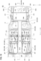
- FIG. 15 is a plan view showing the exterior of the cabin R of the electromotive vehicle 201
- FIG. 16 is a sectional view taken along line A-A of FIG. 15
- FIG. 17 is a sectional view taken along line B-B of FIG. 15
- FIG. 18 is a sectional view taken along line C-C of FIG. 15
- FIG. 19 is a sectional view taken along line D-D of FIG. 15 .
- FIG. 14 a left-side one of right-and-left front seats S1 and a left-side one of right-and-left rear seats S2 are not illustrated. Likewise, a right-side part of the vehicle is illustrated only in FIGS. 17 - 19 for the same reason.
- an arrow Fr and an arrow Rr show the longitudinal direction
- the arrow Fr shows a front (forward) direction
- the arrow Rr shows a rear (rearward) direction
- an arrow Rh and an arrow Lh show the vehicle width direction
- the arrow Rh shows a right (rightward) direction
- the arrow Lh shows a left (leftward) direction.
- the electromotive vehicle 201 of the present embodiment comprises the cabin R which is composed of a passenger compartment R1 where a pair of right-and-left front seats S1 and a pair of right-and-left rear seats S2 for seating of passengers are arranged and a baggage compartment R2 which is positioned behind the passenger compartment R1 where baggage and the like are loaded.
- This electromotive vehicle 201 may comprise, as shown in FIGS. 14 and 15 , a dash panel 202 which forms a front wall of the cabin R , a pair of right-and-left side sills 203 which extend rearward from respective lower portions of both ends, in the vehicle width direction, of the dash panel 202 , and a pair of right-and-left rear side frames 204 which are connected to respective rear portions of the side sills 203 and extend rearward.
- the electromotive vehicle 201 further comprises a front floor panel 205 which forms a floor surface of the passenger compartment R1 between the side sills 203 , a rear floor panel 206 which forms a floor surface of the baggage compartment R2 between the rear side frames 204 , and a pair of right-and-left floor frame uppers 207 which extend in the vehicle longitudinal direction from the dash panel 202 to the front floor panel 205.
- this electromotive vehicle 201 may have, as shown in FIGS. 15 and 16 , one or more cross members, particularly a pair of right-and-left first floor cross members 208 , a pair of right-and-left second floor cross members 209 , and a pair of right-and-left third floor cross members 210 , which all interconnect the right-and-left side sills 203 in the vehicle width direction, and a fourth floor cross member 211 which interconnects the right-and-left rear side frames 204 in the vehicle width direction.
- one or more cross members particularly a pair of right-and-left first floor cross members 208 , a pair of right-and-left second floor cross members 209 , and a pair of right-and-left third floor cross members 210 , which all interconnect the right-and-left side sills 203 in the vehicle width direction, and a fourth floor cross member 211 which interconnects the right-and-left rear side frames 204 in the vehicle width direction.
- the dash panel 202 is a panel member with a specific thickness in the vehicle longitudinal direction, which is configured such that a central portion, in the vehicle width direction, of its lower end protrudes upward.
- both ends, in the vehicle width direction, of the dash panel 202 may be connected to hinge pillars (not illustrated) which are provided to stand at respective front ends of the right-and-left side sills 203.
- a dash cross member 212 which extends in the vehicle width direction along the lower end of the dash panel 202 and are connected to the hinge pillars (not illustrated) may be joined to a front face of the dash panel 202 as shown in FIGS. 14 and 16 .
- the dash cross member 212 is a vehicle-body frame member with a cross section which forms a closed-cross section with the dash panel 202.
- the cross section of the dash cross member 212 may be of a roughly hat shape protruding in the vehicle front direction.
- Each of the right-and-left side sills 203 may be another vehicle-body frame member with a closed-cross section, which is formed by a side sill inner 203a which is positioned on an inward side, in the vehicle width direction, thereof and a side sill outer (not illustrated) which is positioned on an outward side, in the vehicle width direction, thereof as shown in FIG. 14 .
- Each of the right-and-left rear side frames 204 may be further another vehicle-body frame member with a closed-cross section, a front end portion of which is joined to an inward side, in the vehicle width direction, of a rear part of the side sill 203 ,
- This rear side frame 204 is formed by a side frame upper 204a which is positioned at an upper side (see FIG. 18 ) and a side frame lower 204b which is positioned at a lower side (see FIG. 18 ).
- a damper support member 213 to support an upper end of a rear suspension damper may be joined to the side frame upper 204a of the rear side frame 204 at a position in back of the fourth floor cross member 211 described later.
- This damper support member 213 which is particularly a high-rigidity member which is made of aluminum diecast, for example, may be joined to a rear side panel (not illustrated) which forms an inner wall of the baggage compartment R2 , the side frame upper 204a , and the fourth floor cross member 211 described later, thereby serving as a vehicle-body frame member.
- a rear wheel (not illustrated) to be suspended by the rear suspension damper may be disposed below the damper support member 213.
- the front floor panel 205 may be formed by a plate-shaped floor-panel front portion 251 which is joined to a lower end of the dash panel 202 , a kick-up portion 252 which rises upward from a rear end of the floor-panel front portion 251 , and a floor-panel rear portion 253 which extends rearward from an upper end of the kick-up portion 252.
- the floor-panel front portion 251 may form a floor surface of the passenger compartment R1 over a range, in the vehicle longitudinal direction, from the lower end of the dash panel 202 to a front end of the rear seat S2.
- a tunnel portion 251a which protrudes upward with its longitudinal length extending from the dash panel 202 to the kick-up portion may be formed substantially at a central portion, in the vehicle width direction, of the floor-panel front portion 251.
- the tunnel portion 251a may be configured to have a roughly trapezoid-shaped cross section, and some devices, such as the shift lever, are fixed to its upper face.
- a font-seat center console 214 may be fixedly arranged at a position adjacent, in the vehicle width direction, to the right-and-left front seats S1 as shown by a two-dotted broken line in FIG. 16 .
- a pair of right-and-left tunnel frames 215 which extend in the vehicle longitudinal direction along both-side lower ends of the tunnel portion 251a may be joined to a lower face of the floor-panel front portion 251.
- Each of these tunnel frames 215 may be another vehicle-body frame member which forms a closed-cross section with the floor-panel front portion 251 , and its front end may be connected to the dash cross member 212.
- the kick-up portion 252 may extend obliquely upward-and-rearward from a rear end of the floor-panel front portion 251 as shown in FIG. 16 .
- the floor-panel rear portion 253 may extend, from an upper end of the kick-up portion 252 , rearward and then obliquely rearward- and-downward as shown in FIG. 16 .
- the second outside attachment portion 209a is, as shown in FIG. 17 , formed in a substantially box shape which opens downward and outward, and its cross section forms a closed-cross section together with the side sill 203 and the second floor cross member 209.
- the fastening backet 217 is, as shown in FIG. 17 , integrally formed by a pair of flat-plate shaped lower base portions 217a which are joined to the upper faces of the second inside attachment portions 209b , a flat-plate shaped upper base portion 217b which is joined to the upper face of the tunnel portion 251a , and a pair of flat-plate shaped connection portions 217c which face both side faces of the tunnel portion 25a with a specified gap therebetween.
- the third floor cross member 210 may be another vehicle-body frame member with its cross section which forms a closed-cross section together with the front floor panel 205 , and may be joined to a rear end of the floor-panel front portion 251 and a front end of the floor-panel rear portion 253 , straddling the kick-up portion 252 as shown in FIG. 16 .
- the battery unit 230 to supply the electric power to the motor may be arranged over a range of the passenger R1 and the baggage compartment R2.
- This battery unit 230 comprises, as shown in FIGS. 15 and 16 , a first battery 231 arranged in the baggage compartment R2 , a second battery 232 arranged in the passenger compartment R1 , and a battery case 233 storing and holding these batteries as a unit.
- the first battery 231 is configured to be relatively long in the vehicle width direction and roughly rectangular in the plan view, and provided at a front part of the rear floor panel 206 such that its rear side is positioned close to a seatback (no reference number attached) of the rear seat S2.
- the battery case 233 may be a high-rigidity case member which is made of the aluminum dicast, for example, which is formed in the roughly T-letter shape in the plan view by a case rear portion 234 to store and hold the first battery 231 and a case front portion 235 to store and hold the second battery 232.
- the case rear portion 234 is configured to have a roughly box shape with length, in the vehicle width direction, thereof extending from one of the rear side frames 204 to the other rear side frame 204 and length, in the longitudinal direction, thereof extending from the fourth floor cross member 211 to a central portion, in the vehicle longitudinal direction, of the rear floor panel 206.
- the case rear portion 234 may be, as shown in FIG. 15 , provided with a pair of right-and-left first fixation portions 234a to be fixed to the rear side frames 204 behind the damper support members 213 and a pair of right-and-left second fixation portion 234b to be fixed to the damper support members 213.
- each of the right-and-left second fixation portions 234b may have a flat-plate shape, which protrudes to the outward side, in the vehicle width direction, from a side face of a front end portion of the case rear portion 234 , and is fixedly fastened to a single weld bolts 220 which are provided at the damper support member 213.
- the case front portion 235 may be, as shown in FIG. 15 , provided with a pair of right-and-left third fixation portions 235a to be fixed to a closed-cross section portion which is formed by the floor-panel front portion 251 and the second floor cross members 209 and the second inside attachment portions 209b.
- the cabin structure of the electromotive vehicle 201 may further comprise the battery case, particularly the high-rigidity battery case 233 , which store the first battery 231 positioned behind the rear seats S2 and the second battery 232 positioned between the rear seats S2.
- This battery case 233 may be integrally formed in the roughly T-letter shape in the plan view by the case rear portion 234 which extends from the outward side of one of the rear seats S2 to the outward side of the other rear seat S2 in the vehicle width direction and stores the first battery 231 and the case front portion 235 which extends forward from the case rear portion 234 through a space between the rear seats S2 and stores the second battery 232.
- case rear portion 234 of the battery case 233 may be fixed to a pair of high-rigidity portions of the vehicle body (the rear side frame 204 and the damper support members 213 ) which are positioned behind the rear seat S2.
- case front portion 235 of the battery case 233 may be fixed to the high-rigidity portions of the vehicle body (the closed-cross section portion C1 formed by the second floor cross member 209 , the closed-cross section portion C3 formed by the fastening bracket 217 , and the closed-cross section portion C2 formed by the second inside attachment portion 209b ) which are positioned before the seatbacks of the rear seats S2.
- the battery volume of the electromotive vehicle 201 can be ensured by the first and second batteries 231 , 232 arranged in the cabin R.
- the present cabin structure of the electromotive vehicle 201 can protect these batteries 231 , 232 from an unpredicted outer force.
- the present cabin structure of the electromotive vehicle 201 can connect, in the vehicle width direction, portions which are close to load-input points of the vehicle body where an input load from the rear wheel is inputted by the case rear portion 234.
- the cabin structure of the electromotive vehicle 201 can prevent that the case rear portion 234 has bending or torsion due to the input load from the rear wheel. Thereby, the cabin structure of the electromotive vehicle 201 can make the battery case 233 serve as the frame member to reinforce the vehicle body, so that the bending rigidity or the torsional rigidity of the vehicle body can be improved.
- the cabin structure of the electromotive vehicle 201 can suppress the vehicle's weight compared to a case where the portions of the vehicle body which are close to the load-input points are interconnected, in the vehicle width direction, by using a different connecting member from the battery case 233. Accordingly, the cabin structure of the electromotive vehicle 201 can compatibly attain ensuring the battery volume and improving the vehicle-body rigidity, suppressing the vehicle's weight increase.
- the cabin structure of the electromotive vehicle 201 may have the rear floor panel 206 forming the floor surface of the baggage compartment R2 which is positioned on the rearward side of the front floor panel 205.
- the first battery 231 may be arranged above the rear floor panel 206.
- the case rear portion 234 of the battery case 233 may be fixed to the high-rigidity portions (the rear side frame 204 and the damper support member 213 ) which are adjacent, in the vehicle width direction, to the rear floor panel 206.
- the case rear portion 234 of the battery case 233 can be fixed closer to the right-and-left load-input points in the cabin R where the passenger compartment R1 and the baggage compartment R2 are integrally formed, for example.
- the cabin structure of the electromotive vehicle 201 can securely make the battery case 233 serve as the frame member to reinforce the vehicle body, thereby improving the vehicle-body rigidity.
- the cabin structure of the electromotive vehicle 201 may further have the pair of right-and-left rear side frames 204 where the end portions, in the vehicle width direction, of the rear floor panel 206 are joined.
- the case rear portion 234 of the battery case 233 is fixed to the right-and-left rear side frames 204 at both end portions, in the vehicle width direction, thereof.
- the case rear portion 234 of the battery case 233 is fixed to the rear side frames 204 as an existing high-rigidity portion of the vehicle body, it is unnecessary to provide any other additional high-rigidity portion in the baggage compartment R2.
- the cabin structure of the electromotive vehicle 201 can securely suppress the vehicle body's torsion to be caused by the input load from the rear wheel by means of the battery case 233.
- the cabin structure of the electromotive vehicle 201 may comprise the damper support member 213 which is positioned close to the outward side of the rear floor panel 206 and supports the upper end of the rear suspension damper.
- the case rear portion 234 of the battery case 233 is fixed to the damper support member 213 at the end portion, in the vehicle width direction, thereof.
- the case rear portion 234 of the battery case 233 is fixed to the damper support member 213 as the existing high-rigidity portion, any other additional high-rigidity portion is unnecessary in the baggage compartment R2. Moreover, since the damper support members 213 where the input load from the rear wheel directly acts is interconnected, in the vehicle width direction, by the case rear portion 234 , the cabin structure of the electromotive vehicle 201 can suppress the vehicle body's torsion to be caused by the input load from the rear wheel by means of the battery case 233 more securely.
- the case front portion 235 of the battery case 233 may extend through the space between the rear seats S2 , and has the longitudinal length such that the foot space of the passenger seated in the rear seat S2 is divided, in the vehicle width direction, thereby.
- the battery volume can be ensured by utilizing the space between the rear seats S2 , and the independent seat spaces can be formed by the case front portion 235 separating the right-and-left rear seats S2.
- the cabin structure of the electromotive vehicle 201 can properly prevent deterioration of appearance between the right-and-left rear seats S2 , which may be caused by the case front portion 235 of the battery case 233 , and also improve the livability of the passenger and the high-quality feeling in the rear part of the passenger compartment R1.
- the case front portion 235 of the battery case 233 may be fixed to the second inside attachment portions 209b to attach the front seats S1. According to this structure, since the case front portion 235 of the battery case 233 is fixed to the second inside attachment portions 209b as the existing high-rigidity portions, it is unnecessary to provide any other additional high-rigidity portions in the passenger compartment R1. Accordingly, the cabin structure of the electromotive vehicle 201 can improve the vehicle-body rigidity without increasing the vehicle weight.
- the cabin structure of the electromotive vehicle 201 may further comprise the pair of right-and-left side sills 203 extending in the vehicle longitudinal direction and joined to the both-side end portions, in the vehicle width direction, of the front floor panel 205 and the second floor cross members 209 interconnecting the side sills 203 in the vehicle width direction and forming the closed-cross sections extending in the vehicle width direction together with the front floor panel 205.
- the case front portion 235 of the battery case 233 may be fixed to the closed-cross sections formed by the front floor panel 205 and the second floor cross members 209.
- the cabin structure of the electromotive vehicle 201 can improve the vehicle-body rigidity without increasing the vehicle weight.
- the front floor panel 205 may comprise the tunnel portion 251a protruding upward and extending in the vehicle longitudinal direction at the central portion, in the vehicle width direction, thereof.
- the case front portion 235 of the battery case 233 is fixed to the high-rigidity portions (the closed-cross section portion C3 formed by the fastening backet 217 ) which are arranged above the tunnel portion 251a and provided at the tunnel portion 251a.
- the case front portion 235 of the battery case 233 can be supported securely, thereby improving the vehicle-body rigidity securely.
Landscapes
- Engineering & Computer Science (AREA)
- Mechanical Engineering (AREA)
- Transportation (AREA)
- Chemical & Material Sciences (AREA)
- Combustion & Propulsion (AREA)
- Aviation & Aerospace Engineering (AREA)
- Physics & Mathematics (AREA)
- Thermal Sciences (AREA)
- Body Structure For Vehicles (AREA)
Abstract
Description
- The present invention relates to a cabin structure of a vehicle, comprising a battery for drive which is installed above a floor of the vehicle, such as a hybrid vehicle or an electric automobile. The present invention also relates to a method of manufacturing a vehicle.
- It is known, as exemplified by
Japanese Patent Laid-Open Publication No. 2005-71759 - However, this arrangement of the battery for drive above the rear floor causes a floor surface of a baggage compartment in the cabin to be located at a high level improperly, so that there is a problem that the substantial height of a baggage space may be decreased. In a stylishness-oriented vehicle with a relatively low roof height, in particular, this problem may become dominant.
- Meanwhile, a structure in which the battery for drive, i.e., the battery case for this battery, is arranged in a space below a seat cushion of a rear seat provided above the floor has been proposed as disclosed in
Japanese Patent Laid-Open Publication No. 2009-29159 - Moreover, even in a case where a seatback of the rear seat is configured to be forward foldable so that the substantially-flat floor surface of the baggage compartment can be enlarged over an arrangement area of the rear seat in the cabin, the above-described layout of the battery (battery case) installed above the floor may hinder this enlargement trial of the flat floor surface of the baggage compartment.
- The present invention has been devised in view of the above-described problems, and an object of the present invention is to form the substantially-flat and/or enlarged floor surface of the baggage compartment, ensuring the height of the baggage space and the head clearance of the passenger seated in the rear seat, without deteriorating the battery volume, in a forward-folded state of the seatback of the rear seat.
- Another object of the present invention is to ensure the essential function of a center console even if the battery (case) is expanded and enlarged forward.
- Further another object of the present invention is to make the battery case storing the battery for drive and improve the vehicle-body rigidity.
- The present invention is defined in independent claims. Particularly, a cabin structure of a vehicle, which is provided with a floor forming a bottom face of a cabin, right-and-left front seats arranged to be laterally separated above a front part of the floor, a front-seat center console interposed between the right-and-left front seats, right-and-left rear seats arranged to be laterally separated above a rear part of the floor behind a kick-up portion and configured to be forward foldable, and a rear-seat center console interposed between the right-and-left rear seats, includes a first battery for drive provided above a baggage-compartment part of the floor behind seatbacks of the rear seats and extending in a vehicle width direction and a second battery for drive provided above a part of the floor between the right-and-left rear seats and extending in a vehicle longitudinal direction, wherein the first and second batteries are arranged in a T-letter shape in a plan view, right-and-left both end portions of the first battery are fixed to the baggage-compartment part of the floor, a front end portion of the second battery extending forward beyond the kick-up portion toward an inside of the front-seat center console is fixed to the floor, and each back face portion of the respective seatbacks of the right-and-rear rear seats which are positioned in a forward-folded state and an upper face portion of the first battery are configured to form a substantially flat and enlarged floor surface of a baggage compartment.
- According to the present invention, the sufficient battery volume, the height of the baggage space, and the head clearance of the passenger seated in the rear seat can be ensured, and also the substantially-flat floor surface of the baggage compartment can be properly enlarged in the forward-folded state of the seatbacks of the right-and-left rear seats.
- In an embodiment of the present invention, the cabin structure of the vehicle may further comprise a middle seatback portion provided between the right-and-left rear seats so as to be forward folded onto an upper face of the rear-seat center console, wherein longitudinal thickness of the middle seatback portion in an upright position may be configured to be smaller than that of each of the seatbacks of the right-and-left rear seats in the upright position such that a back face portion of the middle seatback portion positioned in a forward-folded state and each back face portion of the respective seatbacks of the right-and-left rear seats positioned in the forward-folded state form a flat surface extending in the vehicle width direction.
- According to this embodiment, since the back face portion of the middle seatback portion positioned in the forward-folded state and each back face portion of the respective seatbacks of the right-and-left rear seats positioned in the forward-folded state form the flat surface extending in the vehicle width direction, flatness of the floor surface of the baggage compartment can be improved.
- In another embodiment of the present invention, an upper portion of the rear-seat center console may be provided with a seatback placement portion where the forward-folded middle seatback portion is received and a protrusion portion which is configured to protrude in front of the seatback placement portion, a function panel to provide an input/output function to a passenger seated in the rear seat may be arranged at a portion of the protrusion portion which faces the passenger seated in the rear seat, and the function panel may be covered with the middle seatback portion positioned in the forward-folded state.
- According to this embodiment, the function panel of the rear-seat center console can be properly protected by a front portion of the forward-folded middle seatback portion against a loaded baggage.
- In another embodiment of the present invention, a rear portion of the front-seat center console and the front end portion of the second battery may be fixed to a central portion, in the vehicle width direction, of the floor by a common attaching member.
- According to this embodiment, attachment portions of the console's rear portion and the battery's front portion can be compact, so that erosion of respective volumes of the both by the attachment portions can be suppressed.
- In another embodiment of the present invention, the front-seat center console may comprise storage portion or an object storage portion which opens upward and an air-conditioning discharge port for the rear seat which is arranged behind the object storage portion, the front end portion of the second battery may be positioned close to a rear end portion of the object storage portion, and the air-conditioning discharge port may be positioned above the front end portion of the second battery.
- According to this embodiment, the air-conditioning discharge port for the rear seat can be located at an appropriate level for the rear seat's passenger, and also the second battery can be extended to the rear end portion of the object storage portion without being hindered by the air-conditioning discharge port, thereby increasing the battery volume properly.
- In another embodiment of the present invention, a duct to introduce conditioning air from an air-conditioning unit provided at a front part of the cabin to the air-conditioning discharge port for the rear seat may be arranged inside the front-seat center console, the object storage portion may be formed in a cylindrical shape with a bottom, which includes a bottom face portion and right-and-left side wall portions, and the duct may be configured to extend from below the object storage portion to the air-conditioning discharge port for the rear seat, passing through a space between a side face portion of the front-seat center console and the side wall portion of the object storage portion.
- According to this embodiment, since the battery for the drive can be made close to the rear end portion of the object storage portion without being hindered by the duct, thereby increasing the battery volume properly.
- In another embodiment of the present invention, the cabin structure of the vehicle may further comprise an aluminum-made battery case in which a case rear portion to store the first battery and a case front portion to store the second battery are integrally formed substantially in the T-letter shape in the plan view, wherein the case rear portion may be fixed to a pair of right-and-left high-rigidity vehicle-body portions which are located in back of the right-and-left rear seats, and the case front portion may be fixed to another pair of right-and-left high-rigidity vehicle-body portions which are located in front of the seatbacks of the right-and-left rear seats.
- According to this embodiment, since the battery case can be made to function as a frame member to reinforce the vehicle body, so that the bending and/or torsional rigidity of the vehicle body can be improved.
- In another embodiment of the present invention, both end portions, in the vehicle width direction, of the case rear portion of the battery case may be fixed to right-and-left rear side frames of the vehicle.
- According to this embodiment, since the case rear portion of the battery case is fixed to the rear side frame as an existing high-rigidity member, no additional high-rigidity portion extending in the vehicle with direction is necessary in the baggage compartment. Further, since the right-and-left rear side frames where a load is easily inputted from a rear wheel are interconnected, in the vehicle width direction, by the case rear portion of the battery case, torsional deformation of vehicle body which is caused by the input load from the rear wheel can be suppressed.
- In another embodiment of the present invention, the cabin structure of the vehicle may further comprise right-and-left damper support portions to support respective upper ends of right-and-left rear-suspension dampers, wherein the both end portions, in the vehicle width direction, of the case rear portion of the battery case may be fixed to the right-and-left damper support portions.
- According to this embodiment, since the damper support portions where the input load from the rear wheel is directly applied is interconnected, in the vehicle width direction, by the case rear portion of the battery case, the torsional deformation of vehicle body caused by the input load from the rear wheel can be suppressed.
- In another embodiment of the present invention, the floor may be provided with a floor tunnel protruding upward and extending in the vehicle longitudinal direction substantially at a center, in the vehicle width direction, of the floor, and a front end portion of the case front portion of the battery case may be fixed to a high-rigidity portion of the floor.
- According to this embodiment, since the front-and-rear end portions of the battery case are fixed to the high-rigidity members of the vehicle body which are separated from each other in the vehicle longitudinal direction., the bending rigidity of the vehicle in a side view can be improved.
- The present invention will become apparent from the following description which refers to the accompanying drawings.
-
-
FIG. 1 is a perspective sectional view of a main part of a vehicle of the present embodiment, when viewed from a front, left and upper side of the vehicle. -
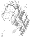
FIG. 2 is a perspective sectional view of the main part of the vehicle shown inFIG. 1 in which illustration of a front seat is omitted, and a front-seat center console portion and a rear-seat center console portion are shown by an imaginary line. -
FIG. 3 is a perspective sectional view of the main part of the vehicle shown inFIG. 1 in a state where a rear-seat armrest is forward folded. -
FIG. 4 is a perspective sectional view of the main part of the vehicle shown inFIG. 1 in a state where seatbacks of rear seats and a middle seatback portion are all forward folded. -
FIG. 5 is a perspective view of the main part of the vehicle of the present embodiment, when viewed from a rear, left and upper side of the vehicle. -
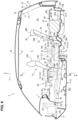
FIG. 6 is a sectional view taken along line A-A ofFIG. 1 . -
FIG. 7 is an enlarged view of the main part shown inFIG. 6 . -
FIG. 8 is an enlarged view of the main part shown inFIG. 7 in a state where the seatbacks of the rear seats and the middle seatback portion are all forward folded. -
FIG. 9 is a perspective view explaining an arrangement structure of a supply duct for the rear seat. -
FIG. 10 is a sectional view taken along line B-B ofFIG. 6 . -
FIG. 11 is a perspective sectional view of an attaching member to attach and support an object storage portion and its surroundings, when viewed from a rear side of the vehicle. -
FIG. 12 is a perspective sectional view of an attaching member to attach and support a second battery case and its surroundings, when viewed from a front side of the vehicle. -
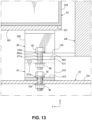
FIG. 13 is a sectional view taken along line C-C ofFIG. 11 . -
FIG. 14 is an exterior perspective view showing an exterior of a cabin of an electromotive vehicle, when viewed from the rear side of the vehicle, according to another embodiment. -
FIG. 15 is a plan view showing the exterior of the cabin of the electromotive vehicle. -
FIG. 16 is a sectional view taken along line A-A ofFIG. 15 . -
FIG. 17 is a sectional view taken along line B-B ofFIG. 15 . -
FIG. 18 is a sectional view taken along line C-C ofFIG. 15 . -
FIG. 19 is a sectional view taken along line D-D ofFIG. 15 . - Hereafter, an embodiment of the present invention will be described specifically referring to the drawings. In the drawings, an arrow F shows a front (forward) side of a vehicle V, and an arow U shows an upper (upward) side of the vehicle V, an arrow Ri shows a right (rightward) side of the vehicle V, and an arrow Le shows a left (leftward) side of the vehicle V. Basically, in the flowing description, "front (forward)," "rear (rearward)," "right (rightward)," "left (leftward)," "upper (upward)," and "lower (downward)" show respective directions relative to a position of the vehicle V except for particularly-referred cases.
- The vehicle V of the present embodiment may be, for example, a hybrid electric vehicle (HEV), or a plug-in hybrid electric vehicle (PHEV), which is capable of charging a battery from a home (household) power source, among various types of hybrid vehicle which can produce a driving power by combining an internal combustion engine and an electric motor.
- As shown in
FIGS. 1 - 6 , especiallyFIGS. 5 and6 , the vehicle V of the present embodiment comprises a floor panel (particularly a steel-made floor panel) 1 which mainly forms a floor surface (bottom face) of acabin 2, a pair of right-and-left front seats rear seats - The
floor panel 1 may be integrally formed by afront floor panel 11 which supports the pair offront seats portion 12 which rises upward from a rear end of thefront floor panel 11 and is of a vertical-wall shape, and arear floor panel 13 which extends rearward from the kick-upportion 12. - The
rear floor panel 13 may be integrally formed by a rear-seat cushion panel 131 (rear-seat pan) which supportsrespective seat cushions rear seats compartment floor panel 132 which extends rearward from the rear-seat cushion panel 131 and forms a floor surface of abaggage compartment 2a. - Herein, the baggage-
compartment floor panel 132 may be provided with arecess portion 132a to store a spare tire at a rear-side portion of a central part, in a vehicle width direction, thereof, and arear end panel 14a (seeFIG. 6 ) extending in the vehicle width direction is attached to a rear-end open side of therecess portion 132a. Further, a floor surface of another part of thefloor panel 1 than thebaggage compartment 2a in the cabin 2 (i.e., the floor surface of the part of thefloor panel 1 where a passenger stays, which is located in front of thebaggage compartment 2a) may be formed by thefront floor panel 11, the kick-upportion 12 and the rear-seat cushion panel 131. - As shown in
FIG. 6 , arear end member 14b extending in the vehicle width direction may be fixedly connected to a rear face of therear end panel 14a, and a rear-end closed-cross section 14s extending in the vehicle width direction is formed between therear end member 14b and therear end panel 14a, thereby ensuring the rear vehicle-body rigidity. - Further, as shown in
FIG. 6 , the vehicle V of the present embodiment may be a hatch-back type, in which arear-gate opening 15 which is configured to open rearward is provided at the vehicle rear part, and arear gate 16 is provided so as to open and close thisrear-gate opening 15. - The
rear gate 16 may comprise a rear-gateinner panel 17, a rear-gateouter panel 18, and arear window 19, and the rear-gateinner panel 17 may be covered with arear-gate trim 171 which is an interior member from the side of thecabin 2. - Further, the vehicle V may comprise a steel-made
roof panel 20 as a vehicle roof, and theroof panel 20 may be covered with aroof trim 21 which is another interior member from the side of thecabin 2. The height size of thecabin 2 including thebaggage compartment 2a, except for the front part, may be determined by theroof trim 21, therear-gate trim 171, therear window 19, and others. - As shown in
FIGS. 1 ,5 and6 , thefront floor panel 11 may be provided with atunnel portion 22 which extends in a longitudinal direction between a dash lower panel 4 (dash panel) (seeFIG. 6 ) and the vertical-wall shaped kick-upportion 12 and protrudes toward an inside of thecabin 2. - The
tunnel portion 22, which provides the vehicle-body rigidity mainly, may be joined to the kick-upportion 12 at its rear end portion. Herein, the kick-upportion 12 may be formed in a vertical-wall shape which is higher than the rear end portion of thetunnel portion 22. - A plurality of
cross members 23, 24 (vehicle-body rigidity member) which are spaced apart from each other in the longitudinal direction may be joined to thetunnel portion 22 of thefront floor panel 11 from above on the both sides of thetunnel portion 22. Thecross members tunnel portion 2 and right-and-left side sills 5 (specificallyside sill inners 5a) (the left-side one is only illustrated inFIG. 5 ) as a vehicle-body rigidity member, and, as shown inFIGS. 1 and6 , form closed-cross sections floor panel 11 and those. - As shown in
FIGS. 1 and6 , pluralrear cross members 25, 26 (vehicle-body rigidity members) spaced apart from each other in the longitudinal direction may be joined to therear floor panel 13. The front-end rear cross member 25 (No. 3 cross member) is joined to a front end portion of the rear floor panel 13 (i.e., a front end portion of the rear-seat cushion panel 13) from below and joined to the kick-upportion 12 from behind, and forms a closed-cross section 25s extending in the vehicle width direction between that and a corner portion of therear floor panel 13 and the kick-upportion 12. - The middle rear cross member 26 (No. 4 cross member) may comprise a middle rear cross member upper 26a which faces the
rear floor panel 13 on upper-and-lower both sides and has a hat-shaped cross section opening downward and a middle rear cross member lower 26b which faces therear floor panel 13 on the upper-and-lower both sides and has a hat-shaped cross section opening upward. - The middle rear cross member upper 26a and the middle rear cross member lower 26b may be joined together such that a rear end of the rear-
seat cushion panel 131 is interposed therebetween at their rear-end flange portions, and may also be joined together such that a front end of the baggage-compartment floor panel 132 is interposed therebetween, thereby forming a closed-cross section 26s extending in the vehicle width direction therebetween. - The driver's seat 27 (the right-side
front seat 27 in the present embodiment) among the above-described pair of right-and-leftfront seats seat cushion 27C which forms a sitting face for a passenger (driver), aseatback 27B which extends upward from a rear end portion of theseat cushion 27C and forms a face to receive a passenger's back portion, and aheadrest 27H which is provided at an upper part of theseatback 27B to support a passenger's head portion. - Likewise, as shown in
FIGS. 1 and5 , the assistant seat 28 (the left-side front seat 28in the present embodiment) among the pair of right-and-leftfront seats seat cushion 28C which forms a sitting face for a passenger (assistant), aseatback 28B which extends upward from a rear end portion of theseat cushion 28C and forms a face to receive a passenger's back portion, and aheadrest 28H which is provided at an upper part of theseatback 28B to support a passenger's head portion. - Further, as shown in
FIGS. 1 - 6 , a front-seatcenter console portion 50 is arranged between the driver'sseat 27 and theassistant seat 28, i.e., at a middle part, in the vehicle width direction, of a vehicle body, such that it is interposed between the seat cushions 27C, 28C of the right-and-leftfront seats center console portion 50 will be described specifically later. - As shown in
FIG. 1 and5 , the pair ofrear seats front seats seat cushion panel 131. Therear seats seat cushions headrests seatbacks - Moreover, a rear-seat
center console portion 70 is arranged between the right-and-leftrear seat rear seats middle seatback portion 32 is provided between theseatbacks rear seats - The right-and-left
rear seats center console portion 70 and themiddle seatback portion 32, so that theserear seats center console portion 70 will be described specifically later. - The
middle seatback portion 32 may comprise abody portion 33 and a rear-seat armrest 34. The rear-seat armrest 34 may be configured to be rotatable relative to thebody portion 33 around a support point 36 (armrest support point) shown inFIG. 6 which is provided at a lower part of the armrest 34, that is - the rear-seat armrest 34 is foldable so as to take its forward-folded position and its upright-standing position. - Thus, as shown in
FIG. 1 , the rear-seat armrest 34 taking the upright-standing position forms a front face of an upper part of themiddle seatback portion 32. Meanwhile, as shown inFIGS. 4 and7 , the rear-seat armrest 34 constitutes a horizontal armrest when thearmrest 34 is forward folded. - Herein, as shown in
FIG. 4 , theseatbacks rear seats FIG. 6 ) which is provided at each lower part thereof. - Likewise, the
middle seatback portion 32 may be configured to be forward folded by rotating around another support point 38 (seatback rotational support point) (seeFIG. 6 ) which is positioned below the above-described support point 36 (armrest rotational support point) as shown inFIG. 4 . - Herein, the lower part of the
middle seatback portion 32 may be pivotally supported via the above-describedsupport point 38 relative to an bracket (not illustrated) which rises upward from the rear-seat cushion panel 131. However, themiddle seatback portion 32 may be pivotally supported directly via thesupport point 38 or indirectly by using a bracket or the like relative to therear seats - Herein, as shown in
FIG. 7 , the longitudinal thickness (L32) of themiddle seatback portion 32 in the upright position may be configured to be smaller than that (L30b) of each of theseatbacks rear seats seatback 31B of the left-siderear seat 31 may be set to be equal to that of theseatback 30B of the right-siderear seat 31. Thereby, as shown inFIGS. 4 and8 , according to the vehicle V of the present embodiment, when theseatbacks middle seatback portion 32 is folded onto the rear-seatcenter console portion 70, respective back face portions 30Bu, 31Bu of the forward-foldedseatbacks back face portion 32u of the forward-foldedmiddle seatback portion 32 form a substantially flat surface. - As shown in
FIGS. 1 ,2 and7 , since the vehicle V of the present embodiment is the hybrid electric vehicle (HEV) or the plug-in hybrid electric vehicle (PHEV), the batteries fordrive drive 41 and the second battery fordrive 42 are installed such that they are arranged above thefloor panel 1, respectively. - Each of the first and
second batteries battery cases battery cases - The battery constituting the battery pack may be a lead storage battery, lithium-ion battery, or nickel-hydrogen battery, or a different type of secondary battery. Further, a fuel cell battery may be applicable as well. Each of the
battery cases second batteries upper face portions FIG. 5 . - As shown in
FIGS. 1 ,5 and7 , thefirst battery 41 is arranged in a lower space of thebaggage compartment 2a behind the right-and-leftrear seats battery case 43 of the first battery 41 (hereafter, referred to as the "first battery case 43") extends straight in the vehicle width direction, and is arranged over an almost whole length, in the vehicle width direction, of a front part of the baggage-compartment floor panel 132 which forms the floor surface of thebaggage compartment 2a. Thefirst battery case 43 is stored at a front part of the baggage-compartment floor panel 132 which is located in front of therecess portion 132a storing the spare tire. - As shown in
FIG. 5 , thefirst battery case 43 may be attached to the above-described middlerear cross member 26 and a pair of rear side frames 3 which are provided at both sides of the baggage-compartment floor panel 132 as a vehicle-body rigidity member viabrackets 45 or the like by a fastening member of bolts and nuts. - The
first battery case 43 may be, as shown inFIGS. 4 and8 , arranged behind therear seats front end portion 43f is close to respective rear end portions 30Br, 31Br of the forward-foldedseatbacks rear seats front end portion 43f and the rear end portions 30Br, 31Br. - Further, as shown in
FIG. 4 , thefirst battery case 43 may be arranged such that itsupper face portion 43u and the respective back face portions 30Bu, 31Bu, 32u of theseatbacks middle seatback portion 32, which are all forward folded, form a substantially flat surface. - Particularly, as shown in
FIGS. 4 and6 , above the baggage-compartment floor panel 132 and behind a rear end portion of thefirst battery case 43 is provided a baggage-compartment partition board 40 to vertically partition a rear part of thebaggage compartment 2a, which is configured to extend horizontally and detachable. An arrangement height of thisboard 40 may be set such that itsupper face portion 40u is located substantially at the same level as theupper face portion 43u of thefirst battery case 43. - Accordingly, in a state where the baggage-
competent partition board 40 may be set at its arrangement position, the respectiveupper face portions first battery case 43 and the baggage-compartment partition board 40 form a substantial baggage-compartment floor surface 2F which is different from the baggage-compartment floor surface formed by the upper face portion of the baggage-compartment panel 132 (seeFIGS. 6 and7 ). - Moreover, as shown in
FIGS. 4 and8 , when theseatbacks rear seats middle seatback portion 32 are forward folded, the respective back face portions 30Bu, 31Bu, 32u of thesemembers upper face portions first battery case 43 and the baggage-compartment partition board 40 form a substantially flat and/or large surface. - That is, the baggage-
compartment floor surface 2F formed by the respectiveupper face portions rear seats - Herein, either one of the
seatbacks seatbacks 30b, 31b, 32 can be forward folded independently, which is not illustrated. Thereby, allowing the passenger to be seated in thenon-folded seatback baggage compartment 2a can be compatible. Further, the baggage-compartment partition board 40 is not necessary, so the vehicle may not be provided with this board. Meanwhile, theboard 40 may be configured such that it extends forward so as to be placed from above onto theupper face portion 43u of thefirst battery case 43 and its forward extension portion forms a substantial upper face portion (43u) of thefirst battery case 43. - As shown in
FIGS. 2 ,5 and7 , the second battery fordrive 42 is arranged between the seat cushions 30C, 31C of the right-and-leftrear seats seat cushion panel 131, thesecond battery 42 is not positioned below the seat cushions 30C, 31C of therear seats rear seats seat cushion panel 131. - The
battery case 44 of the second battery 42 (hereafter, referred to as the "second battery case 44") is fixedly attached to the upper face portion of the rear-seat cushion panel 131 by a fastening member of bolts and nuts, not illustrated. As shown inFIG. 7 , thesecond battery case 44 extends forward and straight such that itsrear end portion 44r is arranged close to thefront end portion 43f of a central portion, in the vehicle width direction, of thefirst battery case 43. - Thereby, the first and
second battery cases FIGS. 2 ,5 and7 , thesecond battery case 44 is arranged such that its front portion horizontally extends forward from the kick-upportion 12 along thetunnel portion 22 and is separated upward from theupper face portion 22u of the tunnel portion 22 (seeFIG. 2 ). Herein, in the present embodiment, the battery pack inside thesecond battery case 44 may be composed of one or more batteries, particularly many batteries which are arranged in line along the longitudinal direction, corresponding to thesecond battery case 44 extending in the longitudinal direction, which is not illustrated. Thus, the sufficient battery volume of thesecond battery 42 is ensured by forward extending thesecond battery case 44 beyond the kick-upportion 12. - As shown in
FIGS. 1 ,2 ,5 ,7 and8 , especially inFIG. 8 , thefront end portion 44F of thesecond battery case 44 may extend forward beyond arear end portion 50r of the front-seatcenter console portion 50 so that it can be engaged into the front-seatcenter console portion 50 from behind. Thisfront end portion 44F may be supported by thetunnel portion 22 via an attachingmember 67 described later (FIG. 7 ) inside the front-seatcenter console portion 50. Thereby, a front portion of the second battery case 44 (i.e., the extension portion beyond the kick-up portion 12) is provided to extend horizontally between the attachingmember 67 and the rear-seat cushion panel 131. - As shown in
FIGS. 1 and5 , the front-seatcenter console portion 50 may be connected to a front end of a lower part of a central portion, in the vehicle width direction, of an instrument panel 7 (seeFIG. 6 ) which extends in the vehicle width direction at a front side of thecabin 2 at around its front end. - As shown in
FIGS. 1 ,5 ,6 and7 , the front-seatcenter console portion 50 may comprise acover member 51 as a hollow-box shaped interior member, ashift lever 52, anobject storage portion 53, alid 57, the attaching member 67 (seeFIG. 7 ) to support theobject storage portion 53, and a rear-seat supply duct 62 (seeFIGS. 6 and7 ). - As shown in
FIGS. 1 and5 , thecover member 51 may comprise a pair of right-and-left side face portions 511 (seeFIG. 10 ) which form a side face of thecenter console portion 50, atop face portion 512 which forms a front portion of an upper face portion of thecenter console portion 50, and a rear face portion 513 (seeFIG. 5 ) which is arranged at an upper portion of therear end portion 50r of thecenter console portion 50, which are all decorative panels. - The
shift lever 52 is a lever for shifting a transmission (not illustrated) of the vehicle V according to a passenger's operation. Thisshift lever 52 is arranged at a position which is located at a front side and a central side, in the vehicle width direction, of thetop face portion 512. - As shown in
FIG. 7 , theobject storage portion 53 may be provided at a rear part of the front-seatcenter console portion 50. Thisobject storage portion 53 may comprise abottom wall 531, a pair of right-and-leftside walls 532 which rise from both-side edges of the bottom wall 531 (seeFIG. 10 ), afront wall 533 which rises from a front edge of thebottom wall 531, and arear wall 534 which rises from a rear edge of thebottom wall 531, and also has an openingportion 56 which opens upward, so that theobject storage portion 53 is of a cylindrical shape with floor. The above-describedopening portion 56 may be provided behind thetop face portion 512 of the front-seatcenter console portion 50. Herein, theobject storage portion 53 of the present embodiment is deep enough to store a tablet terminal positioned in a vertical state. - The
lid 57 may be provided above theobject storage portion 53 so as to be configured to open and/or close the openingportion 56. Thelid 57 may comprise a pair of right-and-leftsplit lids portion 56 of theobject storage portion 53. As shown inFIG. 10 , a pair ofpivot portions left side portions center console portion 50. Thesepivot portions split lids side portions 156 viapivotal axes 58a extending in the longitudinal direction. Thus, the right-and-leftsplit lids opening portion 56 is opened at the center. - The
lid 57 positioned in closed state of the openingportion 56 may have the sufficient strength and cushion performance so that it can serve as an armrest for the passenger. Further, an upper face portion of thelid 57 of theobject storage portion 53 may be located at a higher level than thetop face portion 512, and may have largeness and height which can make a front arm of the front-seat passenger (seated in thefront seats 27, 28) be properly placed on that. - Herein, the front-seat
center console portion 50 of the present embodiment may have not only theshift lever 52 but some other operational portions to conduct various setting of the vehicle V, such as a navigation system, and some support brackets to support shift operational mechanisms of theshift lever 52 and others, which are not illustrated here. - As shown in
FIG. 5 , the front-seatcenter console portion 50 may be a console with a rear vent for air-conditioning of the rear-seat passenger, and an air-conditioning discharge port 60 for the rear-seat passenger (seated in therear seats 30, 31) may be formed at therear face portion 513 of the above-describedcover member 51. - As shown in
FIG. 7 , therear face portion 513 may be arranged behind theobject storage portion 53 and substantially at the same level as thetop face portion 512, and the air-conditioning discharge port 60 formed at the central portion, in an elevational view, of therear face portion 513 may be configured to be inclined obliquely downward-and-rearward so as to face a head-chest portion of the rear-seat passenger. Herein, thisdischarge port 60 is provided with a louver which closes or opens thedischarge port 60 and changes an air-supply direction. - Particularly, as shown in
FIG. 6 , inside the instrument panel 7 disposed at the front side of thecabin 2 are provided an air-conditioning unit 100 (air-conditioner) and a front-seat supply duct 101 to supply conditioning air (cool/warm air) from the air-conditioning unit 100 to a front-seat discharge port (not illustrated) which is provided at a dashboard. - The rear-
seat supply duct 62 may be connected to an upstream side of the front-seat supply duct 101, and a part of the conditioning air flowing from the air-conditioning unit 100 to the front-seat discharge port (not illustrated) through the front-seat supply duct 101 is divided into the rear-seat supply duct 62. - The rear-
seat supply duct 62 may be provided to penetrate (extend) the inside of the front-seatcenter console portion 50 in the longitudinal direction, and its rear end portion (66b) may be connected to the rear-seat discharge port 60 provided at therear face portion 513 of the front-seatcenter console portion 50. Arear blower 102 may be arranged at a portion near a connection portion of the rear-seat supply duct 62 to the front-seat supply duct 101, i.e., at its upstream-side portion. - When the air-
conditioning unit 100 is operated, part of the conditioning air is discharged from the front-seat discharge port (not illustrated), and the rest of the conditioning air is supplied toward the rear-seat supply duct 62, which is then supplied with pressure toward the rear-seat discharge port 60 through the rear-seat supply duct 62 by therear blower 102. - Next, an arrangement route of the rear-
seat supply duct 62 will be described specifically. As shown inFIGS. 6 ,7 and9 , the rear-seat supply duct 62 may include arearward arrangement portion 63, a pair of right-and-leftoutward arrangement portions 64, a pair of right-and-leftupward arrangement portions 65, and a pair of right-and-left upper-rearward arrangement portions 66, which are located along a conditioning-air flowing direction from its upstream side toward its downstream side. - The
rearward arrangement portion 63 may be arranged rearward from its connection portion to the front-seat supply duct 101 along theupper face portion 22u of thetunnel portion 22. As shown inFIGS. 7 and9 , a rear part of therearward arrangement portion 63 may be arranged rearward from a front side of thefront wall 533 of theobject storage portion 53 such that it goes into a space which is positioned just below thebottom wall 531 of theobject storage portion 53, i.e., between thebottom wall 531 and theupper face portion 22u of thetunnel portion 22. - As shown in
FIGS. 7 and9 , this rear part of therearward arrangement portion 63 may be arranged substantially horizontally up to a position which is located at the central portion, in the vehicle width direction, of theobject storage portion 53 and also located just before therear wall 534 of theobject storage portion 53 in the longitudinal direction (seeFIG. 7 ). That is, arear end portion 63a of therearward arrangement portion 63 is located just below thebottom wall 531 of theobject storage portion 53. - As shown in
FIGS. 9 and10 , the pair of right-and-leftoutward arrangement portions 64 may extend substantially horizontally from therear end portion 63a of therearward arrangement portion 63 toward right-and-left both sides in the vehicle width direction, so that each inside of the right-and-leftoutward arrangement portions 64 is continuous to an inside of therearward arrangement portion 63 via therear end portion 63a. Thus, the rear-seat supply duct 62 is divided into the right-and-left sides at the position just below thebottom wall 531 of theobject storage portion 53. - That is, the pair of right-and-left
outward arrangement portions 64 are arranged toward the outward sides in the vehicle width direction, i.e., the opposite sides to each other, from therear end portion 63a of therearward arrangement portion 63. Eachoutward end portion 64b of the right-and-leftoutward arrangement portions 64 is positioned in a space S between theside face portion 511 of the front-seatcenter console portion 50 and theside wall 532 of theobject storage portion 53. - Each of the
upward arrangement portions 65 may be arranged vertically upward along theside wall 532 of theobject storage portion 53 in the space S between theside face portion 511 of the front-seatcenter console portion 50 and theside wall 532 of theobject storage portion 53. Further, theupward arrangement portion 65 may be connected to theoutward end portion 64b, in the vehicle width direction, of theoutward arrangement portions 64 at itslower end portion 65a, and, as shown inFIGS. 7 and9 , it may be arranged to extend up to an upper level corresponding to the rear-seat discharge port 60. - Herein, as shown in
FIG. 10 , the space S between theside face portion 511 of the front-seatcenter console portion 50 and theside wall 532 of theobject storage portion 53 may exist as a dead space at a position which is just below theside portion 156 of the openingportion 56 of theobject storage portion 53 at the rear part of the front-seatcenter console portion 50. In the present embodiment, as described above, thepivot portion 58 to pivotally support theopenable split lid 571 is provided at theside portion 156 of the openingportion 56 of the front-seatcenter console portion 50. Accordingly, the width of the above-described space S is configured to be relatively large compared to a structure which has no pivot portion at theside portion 156 of the openingportion 56 like thepivot portion 58 of the present embodiment. - In the present embodiment, the
upward arrangement portion 65 may be arranged over a whole length, in the vertical direction, of the above-described space S, so that this space S, i.e., the wide dead space, can be utilized (seeFIG. 10 ). - Herein, the
upward arrangement portion 65 is not limited to the above-described vertical arrangement (seeFIGS. 7 and9 ), and it may be arranged in an inclined shape in a side view of the vehicle V such that its upper side is located at a rear position, which is not illustrated. In any case, theupward arrangement portion 65 is positioned on a forward side of therear wall 534 of theobject storage portion 53. - Thus, as shown in
FIG. 7 , theupward arrangement portion 65 may be arranged in front of thefront end portion 44F of thesecond battery case 44 which is positioned on the rearward side of therear wall 534 of theobject storage portion 53. Accordingly, since theupward arrangement portion 65 is not disposed on the side of thefront end portion 44F, the width, in the vehicle width direction, of thesecond battery case 44 is not restrained improperly by thisupward arrangement portion 65, thereby ensuring the sufficient battery volume. - Further, each of the pair of right-and-left upper-
rearward arrangement portions 66 may be arranged in the longitudinal direction at the level corresponding to the rear-seat discharge port 60, in other words, above theupper face portion 44u of thefront end portion 44F of thesecond battery case 44. Afront end portion 66a of the upper-rearward arrangement portion 66 may be connected to anupper end portion 65b of the above-describedupward arrangement portion 65. - The upper-
rearward arrangement portion 66 may be substantially horizontally arranged rearward from theupper end portion 65b of theupward arrangement portion 65 to the rear-seat discharge port 60 which is positioned on the rearward side of therear wall 534 of theobject storage portion 53, and itsrear end portion 66b is connected to the rear-seat discharge port 60. Herein, the upper-rearward arrangement portions 66 may be configured such that their rear parts are respectively arranged on an inward side, in the vehicle width direction, of the vehicle body at a position which is located on the rearward side of therear wall 534 of theobject storage portion 53 and also on the forward side of the rear-seat discharge portion 60, and theirrear end portions 66b (inward end portions in the vehicle width direction) are connected to the rear-seat discharge port 60 independently or in a joint manner. - Herein, as shown in
FIG. 7 , thesecond battery case 44 is configured as described above such that itsfront end portion 44F extends forward beyond therear end portion 50r of the front-seatcenter console portion 50 and goes into the inside of the front-seatcenter console portion 50, and the panel-shapedrear face potion 513 where the rear-seat discharge portion 60 is formed is arranged at a higher level than theupper face portion 44u of thefront end portion 44F of thesecond battery case 44. The rear end portion (66b) of the rear-seat supply duct 62 which is connected to the rear-seat discharge port 60, i.e., therear end portion 66b of the upper-rearward arrangement portion 66, is supported from just below by thefront end portion 44F of the second battery case 44 (not illustrated). - Particularly, the
rear end portion 66b of the upper-rearward arrangement portion 66 is fixedly attached to theupper face portion 44u of thefront end portion 44F of thesecond battery case 44 via a bracket or the like (not illustrated). - As shown in
FIGS. 7 ,11 and13 , the attachingmember 67 to support theobject storage portion 53 may be provided between the bottom wall 531 (seeFIG. 13 ) of theobject storage portion 53 and theupper face portion 22u of thetunnel portion 22 inside the front-seatcenter console portion 50. That is, theobject storage portion 53 is supported at theupper face portion 22u of thetunnel portion 22 via the attachingmember 67. - Meanwhile, as shown in
FIGS. 7 ,11 - 13 , thefront end portion 44F of thesecond battery case 44 may extend forward to a position in the vicinity of a rearward side of therear wall 534 of theobject storage portion 53. Further, the attachingmember 67 to support theobject storage portion 53 may also serve as another attaching member to support thefront end portion 44F of thesecond battery case 44. Particularly, theobject storage portion 53 of the front-seatcenter console portion 50 and thefront end portion 44F of thesecond battery case 44 are attached to theupper face portion 22u of thetunnel portion 22 via the common attachingmember 67. - Specifically, as shown in
FIGS. 11 - 13 , the attachingmember 67 may be a steel-plate member which is integrally formed by asupport portion 671 which extends in the vehicle width direction along theupper face portion 22u of thetunnel portion 22 so as to receive the rear part of thebottom wall 531 of theobject storage portion 53 and thefront end portion 44F of thesecond battery case 44 thereon, right-and-left leg portions 672 which extend downward from right-and-left both end portions of thesupport portion 671, and right-and-leftflange portions 673 which extend outward from respective outward ends, in the vehicle width direction, of theleg portions 672 and are placed on the both sides of theupper face portion 22u of thetunnel portion 22. This attachingmember 67 may be configured to have a roughly hat-shaped cross section. As shown inFIG. 13 , for example,bolt insertion holes 671a are formed at both sides of thesupport portion 671 such that they vertically penetrate these both sides, and also boltinsertion holes 673a are formed at the right-and-leftflange portions 673 such that they vertically penetrate these flange portions. - Particularly, as shown in
FIGS. 11 - 13 , at thefront end portion 44F of thesecond battery case 44 are provided a pair offlange portions 144 which extend forward from right-and-left both sides of its lower end portion. A vertically-penetratingbolt insertion hole 144a may be formed at each tip end portion (front end portion) of the pair offlange portions 144 as shown inFIG. 13 . - As shown in
FIG. 11 - 13 , abox support bracket 68 may be provided below theobject storage portion 53 and above the attachingmember 67. Thebox support bracket 68 may comprise a bottom-wall reinforcement portion 681 which supports at least a rear part, in the longitudinal direction, of thebottom wall 531 of theobject storage portion 53 and may be joined to a lower face of thebottom wall 531 for reinforcement (seeFIGS. 11 and13 ), a pair of right-and-leftsupport leg portions 682 which extend downward from right-and-left both sides of the bottom-wall reinforcement portion 681, and right-and-leftflange portions 683 which extend toward the outward side, in the vehicle width direction, from respective lower end portions of thesupport leg portions 682. As shown inFIG. 13 , each tip end portion of theflange portions 683 of thebox support bracket 68 has abolt insertion hole 683a which vertically penetrates that. - The above-described
flange portions 673 of the attachingmember 67 may be placed on theupper face portion 22u of thetunnel portion 22 in a state where theirbolt insertion holes FIG. 13 ) match each other in the vertical direction at the right-and-left sides. Theflange portion 673 and theupper face portion 22u may be fixedly fastened by using a bolt B1 and a nut N1 which are inserted into thebolt insertion holes - Further, the
flange portion 144 provided at thefront end portion 44F of thesecond battery case 44 and theflange portion 683 provided at thebox support bracket 68 may be placed in order on thesupport portion 671 of the attachingmember 67 in a state where the respectivebolt insertion holes flange portions bolt insertion holes - Particularly, the attaching
member 67 is provided just below theobject storage portion 53 in the above-described embodiment, but it may be provided just below thefront end portion 44F of the second battery case instead. In any case, thefront end portion 44F of thesecond battery case 44 can be made to extend more close to therear wall 534 of theobject storage portion 53 compared to a case where the attachingmember 67 is placed between therear wall 534 of theobject storage portion 53 and a front face of thefront end portion 44F of thesecond battery case 44. Accordingly, the sufficient battery volume of thesecond battery 42 can be ensured. - As shown in
FIGS. 1 ,5 and6 , the above-described rear-seatcenter console portion 70 may comprise atop face portion 711 which is provided to rise from the rear-seat cushion panel 131 and forms its upper face as a resin-madeinterior member 71 and a pair of right-and-left side face portions 712 (the left-side one is only illustrated) which extend downward from right-and-left both ends of its upper end, which are all decorative panels. - The above-described
second battery case 44 is stored inside the rear-seatcenter console portion 70 which is partitioned by thetop face portion 711 and the right-and-leftside face portions 712. That is, thesecond battery case 44 is provided inside the rear-seatcenter console portion 70 over its roughly whole length so as to serve as a frame member of the rear-seatcenter console portion 70, thereby reinforcing the rear-seatcenter console portion 70. - Accordingly, the
top face portion 711 and the right-and-leftside face portions 712 may be supported by the rear-seat cushion panel 131 via brackets (not illustrated) disposed inside the rear-seatcenter console portion 70, but theseportions second battery case 44 instead (not illustrated). Specifically, thetop face portion 711 may be supported by thesecond battery case 44. - As shown in
FIGS. 1 ,5 and6 , the rear-seatcenter console portion 70 may be provided at a central part, in the vehicle width direction, of thecabin 2 continuously, in the longitudinal direction, to the above-described front-seatcenter console portion 50. Specifically, as shown inFIGS. 5 and6 , the twocenter console portions top face portion 711 of the rear-seatcenter console portion 70 and a lower end portion of therear face portion 513 which is provided at the rear-seat discharge port 60 of the front-seatcenter console portion 50 are connected through engagement or the like, likewise, a front end portion of the right-side side face portion (not illustrated) of the rear-seatcenter console portion 70 and a rear end portion of the right-side side face portion 511 (seeFIG. 10 ) of the front-seatcenter console portion 50 may be connected, and a front end portion of the left-sideside face portion 712 of the rear-seatcenter console portion 70 and a rear end portion of the left-sideside face portion 511 of the front-seatcenter console portion 50 may be connected. Particularly, the right-and-leftside face portions 511 of the front-seatcenter console portion 50 and the right-and-leftside face portions 712 of the rear-seatcenter console portion 70 are longitudinally connected at a border of those substantially in a flat-surface manner. - The rear-seat
center console portion 70 may comprise, in other words, a rear-seat center console rear-portion 72 which is located above the rear-seat cushion panel 131 and a rear-seat center console front-portion 73 which extends forward before the kick-upportion 12. Further, the rear-seat center console front-portion 73 may be provided with anupper portion 74 which has thesecond battery case 44 therein like the rear-seat center console rear-portion 72 and alower portion 75 which is arranged just below theupper portion 74 and thesecond battery case 44 and does not have thesecond battery case 44 therein. - Herein, the
top face portion 711 and the right-and-left side face portions 712 (the left-side one is only illustrated) of the rear-seatcenter console portion 70 may be configured to extend between the rear-seat center console rear-portion 72 and the rear-seat center console front-portion 73 (theupper portion 74 and the lower portion 75). - Particularly, at the
lower portion 75 without thesecond battery case 44 therein is formed an opening portion 76 (penetration hole) which penetrates in the vehicle width direction. This openingportion 76 provides the ventilating performance, in the vehicle width direction, of a foot space of the rear-seat passengers and also constitutes an exterior design which can provide the rear-seat passenger with a feeling of release. - That is, providing the
opening potion 76 at the level corresponding to the rear-seat passenger's foot can properly improve the comfortableness of the rear-seat passenger without providing the passenger with a feeling of being oppressed, maintaining independence of each of therear seats rear seats center console portion 70. - Decorative panels (not illustrated) are provided at respective inner surfaces, i.e., an upper-side inner surface, a lower-side inner surface, a front-side inner surface, and a rear-side inner surface of the opening
portion 76 which is formed in a cylindrical shape extending in the vehicle width direction, at thelower portion 75, thereby ensuring an exterior design of the inner surfaces of the openingportion 76. - The size, forming position, number and the like of the opening
portion 76 are not limited to the present embodiment. For example, while the openingportion 76 of the present embodiment is provided at a central portion of thelower portion 75 in the elevational view (i.e., in the side view of the vehicle V), at least one of peripheral edges of a front edge, a rear edge, a lower edge and the like of the openingportion 76 may not be provided, the openingportion 76 may be formed at an entire part of thelower portion 75, or the plurality may be arranged at thelower portion 75. Furthermore, the openingportion 76 may be provided between theupper portion 74 and thelower portion 75 which are separated from each other in the vertical direction. - In addition, the thickness, in the vehicle width direction, of the
lower portion 75 is not limited to that which corresponds to thesecond battery case 44, and the right-and-left side face portions 712 (the left-side one is illustrated only) which forms thelower portion 75 may be arranged such that the distance, in the vehicle width direction, of the right-and-leftside face portions 712 is narrower than the width, in the vehicle width direction, of thesecond battery case 44. - As shown in
FIGS. 1 ,5 and7 , thetop face portion 711 of the rear-seatcenter console portion 70 may be provided with ashallow tray 77 which can receive an object, such as a mobile terminal, and aprotrusion portion 80 which protrudes upward in front of thetray 77. - As shown in
FIG. 5 , thetray 77 may comprise a bottom face portion 78a which is horizonal in the vehicle width direction and right-and-leftvertical wall portions 79 which rises from right-and-left both edges of thebottom face portion 78 and extend continuously at the same level along its side edges extending in the longitudinal direction, which is configured in a recess shape such that its lateral cross section opens upward. - As shown in
FIG. 8 , thetray 77 may extend in the longitudinal direction as a placement portion where themiddle seatback portion 32 forward folded is placed, having its longitudinal length which corresponds to the longitudinal length of themiddle seatback portion 32 forward folded and having it lateral width which is substantially the same as the lateral width of themiddle seatback portion 32 forward folded. - The
protrusion portion 80 may protrude upward beyond the upper ends of the right-and-leftvertical wall portions 79 of thetray 77. An upper face portion of theprotrusion portion 80 may comprise a protrusion upper-facerear portion 81 which extends forward from a front end of thetray 77 and is inclined such that its front side is located at a higher level and a protrusion upper-face front portion 82 which extends forward from a front end of the protrusion upper-facerear portion 81 and is slightly inclined such that its front side is located at a lower level. - Specifically, as shown in
FIG. 5 , thebottom face portion 78 of thetray 77 may be configured to be horizonal except its front-side part, and the front-side part of thebottom face portion 78 may be configured to be inclined such that its front side is located at a higher level which corresponds to the level of thevertical wall portion 79. The protrusion upper-facerear portion 81 of theprotrusion portion 80 may be configured to extend obliquely forward-and-upward from a front end of the front-side part of thebottom face portion 78 of thetray 77 in such a manner that this protrusion upper-facerear portion 81 faces the rear-seat passenger in the side view of the vehicle V. - Further, the protrusion upper-face
rear portion 81 of theprotrusion portion 80 may be located at a position where the rear-seat passenger's hand can reach, and thisportion 81 may serve as a function panel face which provides at least one of an input function and an output function for the rear-seat passenger's input/output operation of various kinds of information. - Particularly, the output function is a display (indication portion) or a sound output portion, such as a speaker. In a case where the output function is the display, the function panel face is arranged so that a whole part of an image indicated on the display can be captured (viewed) by the rear-seat passenger.
- The display is a device to project the image by light emitting of a screen, and a liquid crystal display, an organic EL display or the like are applicable. The display may comprise a tach panel which is operable through a touching operation by the passenger.
- The input function is an operation input portion to operate various kinds of vehicle onboard electric device, such as an audio device or a rear-seat heater, or a socket (connection terminal). The operation input portion may include a pushing button, a dial, a dial, a joystick or the like, and the socket incudes a USB socket, an AC socket, and a DC socket, but their arrangement number or kinds are not limited in particular.
- In the present embodiment, as shown in
FIG. 5 ,operation input portions 83 of the audio device, the rear-seat heater, and the like, two USB socket 84, and anAC sockets 85 may be provided at the protrusion upper-face portion 81 as the function panel face. - Further particularly, as shown in
FIG. 8 , the protrusion upper-face portion 81 of theprotrusion portion 80 rises along a shape, in the side view of the vehicle V, of a front portion of themiddle seatback portion 32 forward folded, having substantially the same height as the thickness, in the vertical direction, of the front portion of themiddle seatback portion 32 forward folded at thetop face portion 711 of the rear-seatcenter console portion 70. - The
top face portion 711 of the rear-seatcenter console portion 70 of the present embodiment may smoothly rise upward from the front part of thebottom face portion 78 of thetray 77 toward the protrusion upper-facerear portion 81. Thereby, as shown inFIG. 8 , the front portion of themiddle seatback portion 32 forward folded faces the protrusion upper-facerear portion 81 of theprotrusion portion 80 from behind, thereby protecting the protrusion upper-facerear portion 81 against an outer factor, such as an outer force. - Further, as described above, the
middle seatback portion 32 positioned in the forward-folded state may be supported substantially horizontally at least by thetray 77 at thetop face portion 711 of the rear-seatcenter console portion 70, and theback face portion 32u of themiddle seatback portion 32 may form the flat surface, in the vehicle width direction, together with the back face portions 30Bu, 31Bu of theseatbacks rear seats FIG. 4 ) and may also form the flat surface, in the longitudinal direction, together with theupper face portion 43u of the first battery case 43 (seeFIGS. 4 and8 ). - As shown in
FIGS. 1 ,5 ,6 and8 , the protrusion upper-face front portion 82 of theprotrusion portion 80 may be configured to be slightly inclined such that its front end is located at a position nearly below a lower edge of the rear-seat discharge portion 60, i.e., at a lower edge of therear face portion 513 and its rear end is located at a front end of the protrusion upper-facerear portion 81. Thereby, wind (conditioning air) discharged from the rear-seat discharge portion 60 can be made to flow toward the rear-seat passenger without being hindered by theprotrusion portion 80. - Moreover, as shown in
FIGS. 4 and8 , the protrusion upper-face front portion 82 of theprotrusion portion 80 may be provided to form a substantially flat surface, in the longitudinal direction, together with theback face 32u of themiddle seatback portion 32 forward folded. Thereby, the protrusion upper-face front portion 82 of theprotrusion portion 80 can be configured to be part of the above-described flat and enlarged baggage-compartment floor surface 2Fa. - Particularly, as shown in
FIG. 1 , the cabin structure of the vehicle V of the present embodiment is provided with the floor panel 1 (floor) forming the floor surface of thecabin 2, the seat cushions 30C, 31C of the right-and-leftrear seats floor panel 1, theseatbacks rear seats first battery case 43 arranged above the baggage-compartment floor panel 132 forming the floor surface (bottom face) of thebaggage compartment 2a of thefloor panel 1 which is located behind the seat cushions 30C, 31C. Further, as shown inFIG. 2 , this cabin structure of the vehicle V comprises thesecond battery case 44 arranged between the right-and-left seat cushions 30C, 31C above thefloor panel 1, the rear-seat center console portion 70 (console) covering over theupper face portion 44u and the right-and-left side face portions of thesecond battery case 44, and, as shown inFIGS. 4 and8 , and themiddle seatback portion 32 which are arranged between theseatbacks rear seats center console portion 70. Moreover, as shown inFIG. 7 , the longitudinal thickness (L32) of themiddle seatback portion 32 positioned in the upright position is configured to be smaller than that (L30B, for example) of each of theseatbacks rear seats FIGS. 4 and8 , thefront end portion 43f of thefirst battery case 43 is positioned close to the rear end portions 30Br, 31Br of theseatbacks rear seats seatbacks middle seatback portion 32 which are positioned in the forward-folded state form the flat surface extending in the vehicle width direction, and also form the enlarged baggage-compartment floor surface 2Fa together with theupper face portion 43u of thefirst battery case 43. - According to this structure, the height (level) of the flat and/or enlarged baggage-compartment floor surface 2Fa which is formed by the
seatbacks rear seats middle seatback portion 32 which are all forward folded can be properly low and also the floor area of thebaggage compartment 2a can be properly enlarged, ensuring the sufficient battery volume. - Specifically, since not only the
first battery case 43 but thesecond battery case 44 arranged between the right-and-left seat cushions 30C1, 31C1 are provided above thefloor panel 1, the sufficient battery volume can be ensured. - Further, as shown in
FIG. 8 , since thefront end portion 43f of thefirst battery case 43 is provided close to the rear end portions 30Br, 31Br of theseatbacks rear seats second battery case 44 is arranged between the right-and-left seat cushions 30C, 31C, the substantially-flat and enlarged baggage-compartment surface 2Fa can be formed in a state where theseatbacks rear seats middle seatback portion 32 are all forward folded. - Moreover, since the
second battery case 44 arranged above thefloor panel 1 is provided between the seat cushions 30C, 31C of therear seats seatbacks battery case 44 is arranged below the seat cushions 30C, 31C of therear seats - Meanwhile, since the longitudinal thickness of the
middle seatback portion 32 positioned in the upright state is set to be smaller than that of theseatbacks rear seats FIG. 7 )), the height between therear seats middle seatback portion 32 is forward folded can be made properly low. - Accordingly, without improperly reducing the battery volume, the height (level) of the flat and enlarged baggage-compartment floor surface 2Fa when the
seatbacks rear seats middle seatback portion 32 are all forward folded can be properly low and the floor area of thebaggage compartment 2a can be properly enlarged. - In the present embodiment, as shown in
FIG. 2 , thefloor panel 1 may comprise thefront floor panel 11 having thetunnel portion 22 extending in the longitudinal direction, the kick-upportion 12 rising from the rear end portion of thefront floor panel 11, and the rear-seat cushion panel 131 extending rearward from the upper end portion of the kick-upportion 12, where the seat cushions 30C, 31C of therear seats second battery case 44 is arranged above the rear-seat cushion panel 131 and extends forward beyond the kick-upportion 12 at the position above thetunnel portion 22. - According to this structure, since the
second battery case 44 is arranged to extend forward beyond the kick-upportion 12, the height between the seat cushions 30C, 31C of therear seats - In the present embodiment, as shown in
FIG. 5 , at thetop face portion 711 of the rear-seatcenter console portion 70 may be provided thetray 77 as the placement portion for themiddle seatback portion 32 forward folded and extending in the longitudinal direction and theprotrusion portion 80 protruding beyond thetray 77 at the position in front of thetray 77. Further, the function (panel) face rising along the shape, in the side view of the vehicle V, of the front portion of themiddle seatback portion 32 forward folded at thetop face portion 711 of the rear-seatcenter console portion 70 is provided at the face of theprotrusion portion 80 which faces the rear-seat passenger, i.e., at the protrusion upper-facerear portion 81. - According to this structure, as shown in
FIG. 5 , since the front portion of themiddle seatback portion 32 forward folded come to be close to or substantially contact the protrusion upper-facerear portion 81 as the function (panel) face from behind, the function (panel) face of the rear-seatcenter console portion 70 can be protected by this front portion of themiddle seatback portion 32. Further, thetray 77 can firmly support themiddle seatback portion 32 which is forward folded and placed on thetray 77. - In the present embodiment, as shown in
FIG. 8 , theprotrusion portion 80 and themiddle seatback portion 32 may be configured such that the protrusion upper-face front portion 82 and theback face portion 32u of the forward-foldedmiddle seatback portion 32 form the substantially flat surface in the longitudinal direction. According to this structure, there occurs substantially no step (no level difference) between the protrusion upper-face front portion 82 and theback face portion 32u, thereby contributing to forming the flat floor surface of thebaggage compartment 2a. - Another embodiment of the present invention will be described referring to the drawings.
- Herein, this embodiment has the structure recited in
Claim 1 of the present invention as well as the above-described embodiment, and therefore its specific illustration and description will be omitted here. - The vehicle of this embodiment may be an electromotive vehicle which uses a drive force of an output of a motor, in which part of a battery to supply an electric power to the motor is disposed in a cabin R. A cabin structure of this kind of
electromotive vehicle 201 will be described referring toFIGS. 14 - 19 . -
FIG. 14 is an exterior perspective view showing an exterior of the cabin R of theelectromotive vehicle 201, when viewed from the rear side of the vehicle,FIG. 15 is a plan view showing the exterior of the cabin R of theelectromotive vehicle 201,FIG. 16 is a sectional view taken along line A-A ofFIG. 15 , andFIG. 17 is a sectional view taken along line B-B ofFIG. 15 . Further,FIG. 18 is a sectional view taken along line C-C ofFIG. 15 andFIG. 19 is a sectional view taken along line D-D ofFIG. 15 . - Herein, in order to clarify illustration in
FIG. 14 , a left-side one of right-and-left front seats S1 and a left-side one of right-and-left rear seats S2 are not illustrated. Likewise, a right-side part of the vehicle is illustrated only inFIGS. 17 - 19 for the same reason. - In the figures, an arrow Fr and an arrow Rr show the longitudinal direction, the arrow Fr shows a front (forward) direction, and the arrow Rr shows a rear (rearward) direction. Further, an arrow Rh and an arrow Lh show the vehicle width direction, the arrow Rh shows a right (rightward) direction, and the arrow Lh shows a left (leftward) direction.
- As shown in
FIGS. 14 and15 , theelectromotive vehicle 201 of the present embodiment comprises the cabin R which is composed of a passenger compartment R1 where a pair of right-and-left front seats S1 and a pair of right-and-left rear seats S2 for seating of passengers are arranged and a baggage compartment R2 which is positioned behind the passenger compartment R1 where baggage and the like are loaded. - This
electromotive vehicle 201 may comprise, as shown inFIGS. 14 and15 , adash panel 202 which forms a front wall of the cabin R, a pair of right-and-left side sills 203 which extend rearward from respective lower portions of both ends, in the vehicle width direction, of thedash panel 202, and a pair of right-and-left rear side frames 204 which are connected to respective rear portions of theside sills 203 and extend rearward. - The
electromotive vehicle 201 further comprises afront floor panel 205 which forms a floor surface of the passenger compartment R1 between theside sills 203, arear floor panel 206 which forms a floor surface of the baggage compartment R2 between the rear side frames 204, and a pair of right-and-leftfloor frame uppers 207 which extend in the vehicle longitudinal direction from thedash panel 202 to thefront floor panel 205. - In addition, this
electromotive vehicle 201 may have, as shown inFIGS. 15 and16 , one or more cross members, particularly a pair of right-and-left firstfloor cross members 208, a pair of right-and-left secondfloor cross members 209, and a pair of right-and-left thirdfloor cross members 210, which all interconnect the right-and-left side sills 203 in the vehicle width direction, and a fourthfloor cross member 211 which interconnects the right-and-left rear side frames 204 in the vehicle width direction. - Subsequently, respective elements of the
electromotive vehicle 201 will be described further specifically. As shown inFIG. 14 , thedash panel 202 is a panel member with a specific thickness in the vehicle longitudinal direction, which is configured such that a central portion, in the vehicle width direction, of its lower end protrudes upward. - Herein, both ends, in the vehicle width direction, of the
dash panel 202 may be connected to hinge pillars (not illustrated) which are provided to stand at respective front ends of the right-and-left side sills 203. Adash cross member 212 which extends in the vehicle width direction along the lower end of thedash panel 202 and are connected to the hinge pillars (not illustrated) may be joined to a front face of thedash panel 202 as shown inFIGS. 14 and16 . - The
dash cross member 212 is a vehicle-body frame member with a cross section which forms a closed-cross section with thedash panel 202. The cross section of thedash cross member 212 may be of a roughly hat shape protruding in the vehicle front direction. - Each of the right-and-
left side sills 203 may be another vehicle-body frame member with a closed-cross section, which is formed by a side sill inner 203a which is positioned on an inward side, in the vehicle width direction, thereof and a side sill outer (not illustrated) which is positioned on an outward side, in the vehicle width direction, thereof as shown inFIG. 14 . - Each of the right-and-left rear side frames 204 may be further another vehicle-body frame member with a closed-cross section, a front end portion of which is joined to an inward side, in the vehicle width direction, of a rear part of the
side sill 203, - This
rear side frame 204 is formed by a side frame upper 204a which is positioned at an upper side (seeFIG. 18 ) and a side frame lower 204b which is positioned at a lower side (seeFIG. 18 ). - Further, as shown in
FIGS. 14 and15 , adamper support member 213 to support an upper end of a rear suspension damper (not illustrated) may be joined to the side frame upper 204a of therear side frame 204 at a position in back of the fourthfloor cross member 211 described later. - This
damper support member 213, which is particularly a high-rigidity member which is made of aluminum diecast, for example, may be joined to a rear side panel (not illustrated) which forms an inner wall of the baggage compartment R2, the side frame upper 204a, and the fourthfloor cross member 211 described later, thereby serving as a vehicle-body frame member. Herein, a rear wheel (not illustrated) to be suspended by the rear suspension damper may be disposed below thedamper support member 213. - As shown in
FIGS. 15 and16 , thefront floor panel 205 may be formed by a plate-shaped floor-panel front portion 251 which is joined to a lower end of thedash panel 202, a kick-upportion 252 which rises upward from a rear end of the floor-panel front portion 251, and a floor-panelrear portion 253 which extends rearward from an upper end of the kick-upportion 252. - More specifically, as shown in
FIG. 15 , the floor-panel front portion 251 may form a floor surface of the passenger compartment R1 over a range, in the vehicle longitudinal direction, from the lower end of thedash panel 202 to a front end of the rear seat S2. - Further, as shown in
FIGS. 14 - 16 , atunnel portion 251a which protrudes upward with its longitudinal length extending from thedash panel 202 to the kick-up portion may be formed substantially at a central portion, in the vehicle width direction, of the floor-panel front portion 251. - As shown in
FIG. 17 , thetunnel portion 251a may be configured to have a roughly trapezoid-shaped cross section, and some devices, such as the shift lever, are fixed to its upper face. Herein, a font-seat center console 214 may be fixedly arranged at a position adjacent, in the vehicle width direction, to the right-and-left front seats S1 as shown by a two-dotted broken line inFIG. 16 . - Moreover, as shown in
FIG. 17 , a pair of right-and-left tunnel frames 215 which extend in the vehicle longitudinal direction along both-side lower ends of thetunnel portion 251a may be joined to a lower face of the floor-panel front portion 251. Each of these tunnel frames 215 may be another vehicle-body frame member which forms a closed-cross section with the floor-panel front portion 251, and its front end may be connected to thedash cross member 212. - The kick-up
portion 252 may extend obliquely upward-and-rearward from a rear end of the floor-panel front portion 251 as shown inFIG. 16 . The floor-panelrear portion 253 may extend, from an upper end of the kick-upportion 252, rearward and then obliquely rearward- and-downward as shown inFIG. 16 . - As shown by a two-dotted broken line in
FIG. 15 , a pair of sitting face portions (no reference number attached) for the rear seats S2 may be fixedly placed onto the floor-panelrear portion 253 at both-side positions which are separated from each other in the vehicle width direction, interposing the central portion, in the vehicle width direction, of the floor-panelrear portion 253. - The
rear floor panel 205 may be a panel member which is configured to be recessed downwardly at its central portion, in the vehicle longitudinal direction and in the vehicle width direction, thereof, and as shown inFIG. 16 , its front end is connected to a rear end of thefront floor panel 205 via thefourth cross member 211 described later. - As shown in
FIGS. 14 and15 , each of the right-and-leftfloor frame uppers 207 may be obliquely arranged between theside sill 203 and thetunnel portion 251a of thefront floor panel 205 inside the cabin R such that its rear end is positioned on the outward side, in the vehicle width direction, of its front end. - Particularly, as shown in
FIG. 15 , the floor frame upper 207 is arranged along an imaginary-straight line (not illustrated) which connects a rear end of thefront side frame 216 extending forward from thedash panel 202 and an outward side, in the vehicle width direction, of the firstfloor cross member 208 described later. - This floor frame upper 207 may be provided as another vehicle-body frame member which is joined o the
dash panel 202 and the floor-panel front portion 251 and its cross section forms a closed-cross section together with the floor-panel front portion 251. - Further, a rear end portion of the floor frame upper 207 may be joined to a front end portion of a floor frame lower (not illustrated) which is joined to the lower face of the floor-
panel front portion 251, interposing the floor-panel front portion 251 therebetween. Herein, a rear end portion of the floor frame lower is connected to a front end portion of therear side frame 204, for example. - The right-and-left first
floor cross members 208 may interconnect the right-and-left side sills 203 via thetunnel portion 251a of thefront floor panel 205 at a central portion, in the vehicle longitudinal direction, of the floor-panel front portion 251. - Particularly, the first
floor cross member 208, which is another vehicle-body frame member with its cross section which forms a closed-cross section together with the floor-panel front portion 251, is joined to an upper face of the floor-panel front portion 251. - Further, as shown in
FIGS. 14 and15 , the firstfloor cross member 208 may be connected to theside sill 203 via a firstoutside attachment portion 208a at an outward side, in the vehicle width direction, thereof, and its inward side is connected to thetunnel portion 251a via a firstinside attachment portion 208b. - Particularly, the first
outside attachment portion 208a and the firstinside attachment portion 208b are members where respective front portions of a pair of seat rails of the front seat S1 are fixedly fastened at a position below the upper face of thetunnel portion 251a. - Further particularly, the first
outside attachment portion 208a is formed in a substantially box shape which opens downward and outward, and its cross section forms a closed-cross section together with theside sill 203 and the firstfloor cross member 208. - Meanwhile, the first
inside attachment portion 208b is formed in the substantially box shape which opens downward and inward, and its cross section forms a closed-cross section together with thetunnel portion 251a and the firstfloor cross member 208. - Further, as shown in
FIG. 15 , the right-and-left secondfloor cross members 209 may interconnect the right-and-left side sills 203 via thetunnel portion 251a of thefront floor panel 205 at a central portion, in the vehicle longitudinal direction, of the floor-panel front portion 251 between the firstfloor cross member 208 and the kick-upportion 252. - Particularly, the second
floor cross member 209 is another vehicle-body frame member with its cross section which forms a closed-cross section C1 together with the floor-panel front portion 251, which is joined to the upper face of the floor-panel front portion 251. - As shown in
FIGS. 14 and15 , the secondfloor cross member 209 is connected to theside sill 203 via a secondoutside attachment portion 209a at its outward side, and its inward side is connected to thetunnel portion 251a via a secondinside attachment portion 209b. - Herein, the second
outside attachment portion 209a and the secondinside attachment portion 209b may be members where respective rear portions of the front seat S1 are fixedly fastened at the position below the upper face of thetunnel portion 251a. - Particularly, the second
outside attachment portion 209a is, as shown inFIG. 17 , formed in a substantially box shape which opens downward and outward, and its cross section forms a closed-cross section together with theside sill 203 and the secondfloor cross member 209. - Meanwhile, the second
inside attachment portion 209b may be, as shown inFIG. 17 , formed in the substantially box shape which opens downward and inward, and its cross section forms a closed-cross section C2 together with thetunnel portion 251a and the secondfloor cross member 209. - As shown in
FIG. 17 , afastening bracket 217 which has a substantially crank-shaped cross section and where abattery unit 230 described later may be fixedly fastened is joined to respective upper faces of the secondinside attachment portions 209b of the right-and-left secondfloor cross members 209. Thisfastening bracket 217 may form a pair of right-and-left closed-cross sections C3 together with thetunnel portion 251a and the second inside attachment portions 209B as shown inFIG. 17 , thereby forming a high-rigidity portion at thetunnel portion 251a. - Specifically, the
fastening backet 217 is, as shown inFIG. 17 , integrally formed by a pair of flat-plate shapedlower base portions 217a which are joined to the upper faces of the secondinside attachment portions 209b, a flat-plate shapedupper base portion 217b which is joined to the upper face of thetunnel portion 251a, and a pair of flat-plate shapedconnection portions 217c which face both side faces of the tunnel portion 25a with a specified gap therebetween. - Further, at each of the
upper base portions 217b of thefastening bracket 217 may be formed a bolt insertion whole (no reference number attached) where abolt 218 to be used for fixing of thebattery 230 described later is inserted. Aweld nut 217d to engage with thebolt 218 is joined to a lower face of each of theupper base portions 217b. - The third
floor cross member 210 may be another vehicle-body frame member with its cross section which forms a closed-cross section together with thefront floor panel 205, and may be joined to a rear end of the floor-panel front portion 251 and a front end of the floor-panelrear portion 253, straddling the kick-upportion 252 as shown inFIG. 16 . - The fourth
floor cross member 211 may be arranged at a border of the floor-panelrear portion 253 and therear floor panel 206 as shown inFIG. 16 . This fourthfloor cross member 211 is another vehicle-body frame member which has a closed-cross section, which is formed by a cross member upper 211a which is located at an upper side and a cross member lower 211b which is located at a lower side. - In the
electromotive vehicle 201 provided with the above-described vehicle body, as shown inFIGS. 14 - 16 , thebattery unit 230 to supply the electric power to the motor may be arranged over a range of the passenger R1 and the baggage compartment R2. Thisbattery unit 230 comprises, as shown inFIGS. 15 and16 , afirst battery 231 arranged in the baggage compartment R2, asecond battery 232 arranged in the passenger compartment R1, and abattery case 233 storing and holding these batteries as a unit. - Particularly, the
first battery 231 is configured to be relatively long in the vehicle width direction and roughly rectangular in the plan view, and provided at a front part of therear floor panel 206 such that its rear side is positioned close to a seatback (no reference number attached) of the rear seat S2. - Meanwhile, as shown in
FIG. 5 , thesecond battery 232 may be configured to be also roughly rectangular in the plan view but longer and narrower than thefirst battery 231, which is arranged between the right-and-left rear seats S2. Herein, thesebatteries - As shown in
FIGS. 15 and16 , thebattery case 233 may be a high-rigidity case member which is made of the aluminum dicast, for example, which is formed in the roughly T-letter shape in the plan view by a caserear portion 234 to store and hold thefirst battery 231 and a casefront portion 235 to store and hold thesecond battery 232. - This
battery case 233 may be formed by a plate-shaped lid portion (no reference number attached) which forms its upper face and a storage portion (no reference number attached) which has an upward open portion to be closed with the lid portion. The lid portion is fixedly fastened to the storage portion, and the storage portion is fixedly fastened to a high-rigidity portion of the vehicle body. - Particularly, as shown in
FIG. 15 , the caserear portion 234 is configured to have a roughly box shape with length, in the vehicle width direction, thereof extending from one of the rear side frames 204 to the otherrear side frame 204 and length, in the longitudinal direction, thereof extending from the fourthfloor cross member 211 to a central portion, in the vehicle longitudinal direction, of therear floor panel 206. - The case
rear portion 234 may be, as shown inFIG. 15 , provided with a pair of right-and-leftfirst fixation portions 234a to be fixed to the rear side frames 204 behind thedamper support members 213 and a pair of right-and-leftsecond fixation portion 234b to be fixed to thedamper support members 213. - Particularly, as shown in
FIGS. 15 and18 , each of the right-and-leftfirst fixation portions 234a has a flat-plate shape, which protrudes to the outward side, in the vehicle width direction, from a side face of a rear end portion of the caserear portion 234, and is fixedly fastened to twoweld bolts 219 which are provided at therear side frame 204 with a specified distance, in the vehicle width direction, therebetween. Herein, thefirst fixation portion 234a may be fixed to therear side frame 204 in a state where aspacer 236 is interposed between a lower face of its inward side and an upper face of therear side frame 204. - Meanwhile, as shown in
FIGS. 15 and19 , each of the right-and-leftsecond fixation portions 234b may have a flat-plate shape, which protrudes to the outward side, in the vehicle width direction, from a side face of a front end portion of the caserear portion 234, and is fixedly fastened to asingle weld bolts 220 which are provided at thedamper support member 213. - The case
front portion 235 divides a foot space of the rear seats S2 in the vehicle width direction, and its front end is located inside the front-seat center console 214 as shown inFIGS. 15 and16 . - Particularly, the case
front portion 235 has its longitudinal length extending from a front end of the caserear portion 234 to the secondfloor cross member 209, and is formed in a roughly box shape such that its upper face is located below an upper face of the caserear portion 234. - Herein, as shown by a two-dotted broken line in
FIG. 16 , the casefront portion 235 may be disposed between the right-and-left rear seats S2 and covered with the rear-seat center console 221 which extends rearward continuously from the front-seat center console 214. - The case
front portion 235 may be, as shown inFIG. 15 , provided with a pair of right-and-leftthird fixation portions 235a to be fixed to a closed-cross section portion which is formed by the floor-panel front portion 251 and the secondfloor cross members 209 and the secondinside attachment portions 209b. - Particularly, as shown in
FIGS. 15 and17 , each of the right-and-leftthird fixation portions 235a has a flat-plate shape which protrudes to the outward side, in the vehicle width direction, from s side face of s front end portion of the casefront portion 235, and is fixedly fastened to thefastening bracket 217 by thebolts 218. - As described above, the case
rear portion 234 of thebattery unit 230 may interconnect, in the vehicle width direction, the high-rigidity portions (the right-and-left rear side frames 204 and the right-and-left damper support members 213) which are separated from each other in the vehicle longitudinal direction, interposing the rear suspension damper. - Further, the case front portion of the
battery unit 230 may connect the caserear portion 234 to the high-rigidity portion (the close-cross section portion C1 formed by the secondfloor cross member 209, the closed-cross section portion C3 formed by thefastening backet 217, and the closed-cross section portion C2 formed by the secondinside attachment portion 209b) which is positioned in front of the rear seat S2. - In other words, the
electromotive vehicle 201 may connect the right-and-leftrear side frame 204 and the right-and-leftdamper support member 213 to the high-rigidity portion (the close-cross section portion C1 formed by the secondfloor cross member 209, the closed-cross section portion C3 formed by thefastening backet 217, and the closed-cross section portion C2 formed by the secondinside attachment portion 209b) which is positioned in front of the rear seat S2 via thebattery unit 230. - As described above, the cabin structure of the
electromotive vehicle 201 of the present embodiment comprises thefront floor panel 205 which forms the floor surface of the passenger compartment R1 and the right-and-left rear seats S2 which are provided above thefront floor panel 205 such that these seats S2 are separated from each other in the vehicle width direction and located at the rearmost position. - The cabin structure of the
electromotive vehicle 201 may further comprise the battery case, particularly the high-rigidity battery case 233, which store thefirst battery 231 positioned behind the rear seats S2 and thesecond battery 232 positioned between the rear seats S2. - This
battery case 233 may be integrally formed in the roughly T-letter shape in the plan view by the caserear portion 234 which extends from the outward side of one of the rear seats S2 to the outward side of the other rear seat S2 in the vehicle width direction and stores thefirst battery 231 and the casefront portion 235 which extends forward from the caserear portion 234 through a space between the rear seats S2 and stores thesecond battery 232. - Further, the case
rear portion 234 of thebattery case 233 may be fixed to a pair of high-rigidity portions of the vehicle body (therear side frame 204 and the damper support members 213) which are positioned behind the rear seat S2. - Moreover, the case
front portion 235 of thebattery case 233 may be fixed to the high-rigidity portions of the vehicle body (the closed-cross section portion C1 formed by the secondfloor cross member 209, the closed-cross section portion C3 formed by thefastening bracket 217, and the closed-cross section portion C2 formed by the secondinside attachment portion 209b) which are positioned before the seatbacks of the rear seats S2. - According to this structure, the battery volume of the
electromotive vehicle 201 can be ensured by the first andsecond batteries batteries rigidity battery case 233, the present cabin structure of theelectromotive vehicle 201 can protect thesebatteries - Also, since the case
rear portion 234 of thebattery case 233 is fixed to the high-rigidity portions of the vehicle which are positioned behind the rear seats S2, the present cabin structure of theelectromotive vehicle 201 can connect, in the vehicle width direction, portions which are close to load-input points of the vehicle body where an input load from the rear wheel is inputted by the caserear portion 234. - Additionally, since the case
rear portion 234 is fixed to the high-rigidity portion of the vehicle body which is positioned before the seatbacks of the rear seats S2 via the casefront portion 235, the cabin structure of theelectromotive vehicle 201 can prevent that the caserear portion 234 has bending or torsion due to the input load from the rear wheel. Thereby, the cabin structure of theelectromotive vehicle 201 can make thebattery case 233 serve as the frame member to reinforce the vehicle body, so that the bending rigidity or the torsional rigidity of the vehicle body can be improved. - Moreover, the cabin structure of the
electromotive vehicle 201 can suppress the vehicle's weight compared to a case where the portions of the vehicle body which are close to the load-input points are interconnected, in the vehicle width direction, by using a different connecting member from thebattery case 233. Accordingly, the cabin structure of theelectromotive vehicle 201 can compatibly attain ensuring the battery volume and improving the vehicle-body rigidity, suppressing the vehicle's weight increase. - Also, the cabin structure of the
electromotive vehicle 201 may have therear floor panel 206 forming the floor surface of the baggage compartment R2 which is positioned on the rearward side of thefront floor panel 205. Thefirst battery 231 may be arranged above therear floor panel 206. - The case
rear portion 234 of thebattery case 233 may be fixed to the high-rigidity portions (therear side frame 204 and the damper support member 213) which are adjacent, in the vehicle width direction, to therear floor panel 206. - According to this structure, the case
rear portion 234 of thebattery case 233 can be fixed closer to the right-and-left load-input points in the cabin R where the passenger compartment R1 and the baggage compartment R2 are integrally formed, for example. Thereby, the cabin structure of theelectromotive vehicle 201 can securely make thebattery case 233 serve as the frame member to reinforce the vehicle body, thereby improving the vehicle-body rigidity. - The cabin structure of the
electromotive vehicle 201 may further have the pair of right-and-left rear side frames 204 where the end portions, in the vehicle width direction, of therear floor panel 206 are joined. The caserear portion 234 of thebattery case 233 is fixed to the right-and-left rear side frames 204 at both end portions, in the vehicle width direction, thereof. - According to this structure, since the case
rear portion 234 of thebattery case 233 is fixed to the rear side frames 204 as an existing high-rigidity portion of the vehicle body, it is unnecessary to provide any other additional high-rigidity portion in the baggage compartment R2. - Further, since the rear side frames 204 where the input load easily acts are interconnected, in the vehicle width direction, by the case
rear portion 234, the cabin structure of theelectromotive vehicle 201 can securely suppress the vehicle body's torsion to be caused by the input load from the rear wheel by means of thebattery case 233. - Also, the cabin structure of the
electromotive vehicle 201 may comprise thedamper support member 213 which is positioned close to the outward side of therear floor panel 206 and supports the upper end of the rear suspension damper. The caserear portion 234 of thebattery case 233 is fixed to thedamper support member 213 at the end portion, in the vehicle width direction, thereof. - According to this structure, since the case
rear portion 234 of thebattery case 233 is fixed to thedamper support member 213 as the existing high-rigidity portion, any other additional high-rigidity portion is unnecessary in the baggage compartment R2. Moreover, since thedamper support members 213 where the input load from the rear wheel directly acts is interconnected, in the vehicle width direction, by the caserear portion 234, the cabin structure of theelectromotive vehicle 201 can suppress the vehicle body's torsion to be caused by the input load from the rear wheel by means of thebattery case 233 more securely. - Meanwhile, the case
front portion 235 of thebattery case 233 may extend through the space between the rear seats S2, and has the longitudinal length such that the foot space of the passenger seated in the rear seat S2 is divided, in the vehicle width direction, thereby. According to this structure, the battery volume can be ensured by utilizing the space between the rear seats S2, and the independent seat spaces can be formed by the casefront portion 235 separating the right-and-left rear seats S2. - Further, by covering the case
front portion 235 with the rear-seat center console 221, the cabin structure of theelectromotive vehicle 201 can properly prevent deterioration of appearance between the right-and-left rear seats S2, which may be caused by the casefront portion 235 of thebattery case 233, and also improve the livability of the passenger and the high-quality feeling in the rear part of the passenger compartment R1. - The case
front portion 235 of thebattery case 233 may be fixed to the secondinside attachment portions 209b to attach the front seats S1. According to this structure, since the casefront portion 235 of thebattery case 233 is fixed to the secondinside attachment portions 209b as the existing high-rigidity portions, it is unnecessary to provide any other additional high-rigidity portions in the passenger compartment R1. Accordingly, the cabin structure of theelectromotive vehicle 201 can improve the vehicle-body rigidity without increasing the vehicle weight. - The cabin structure of the
electromotive vehicle 201 may further comprise the pair of right-and-left side sills 203 extending in the vehicle longitudinal direction and joined to the both-side end portions, in the vehicle width direction, of thefront floor panel 205 and the secondfloor cross members 209 interconnecting theside sills 203 in the vehicle width direction and forming the closed-cross sections extending in the vehicle width direction together with thefront floor panel 205. - The case
front portion 235 of thebattery case 233 may be fixed to the closed-cross sections formed by thefront floor panel 205 and the secondfloor cross members 209. - According to this structure, since the case
front portion 235 of thebattery case 233 is fixed to the closed-cross section portions as the existing high-rigidity portions, it is unnecessary to provide any other additional high-rigidity portions in the passenger compartment R1. Accordingly, the cabin structure of theelectromotive vehicle 201 can improve the vehicle-body rigidity without increasing the vehicle weight. - Further, the
front floor panel 205 may comprise thetunnel portion 251a protruding upward and extending in the vehicle longitudinal direction at the central portion, in the vehicle width direction, thereof. Herein, the casefront portion 235 of thebattery case 233 is fixed to the high-rigidity portions (the closed-cross section portion C3 formed by the fastening backet 217) which are arranged above thetunnel portion 251a and provided at thetunnel portion 251a. - According to this structure, even in a case where the
front floor panel 205 is provided with thetunnel portion 251a, the casefront portion 235 of thebattery case 233 can be supported securely, thereby improving the vehicle-body rigidity securely.
Claims (14)
- A cabin structure of a vehicle (V; 201), which is provided with a floor (1; 205, 206) forming a bottom face of a cabin (2; R), right-and-left front seats (27, 28; S1, S 1) arranged to be laterally separated above a front part of the floor (1; 205), a front-seat center console (50; 214) interposed between the right-and-left front seats (27, 28; S1, S1), right-and-left rear seats (30, 31; S2, S2) arranged to be laterally separated above a rear part of the floor (1; 205) behind a kick-up portion (12; 252) and configured to be forward foldable, and a rear-seat center console (70; 221) interposed between the right-and-left rear seats (30, 31; S2, S2), comprising:a first battery for drive (41; 231) provided above a baggage-compartment part of the floor (1; 206) behind seatbacks (30B, 31B) of the rear seats (30, 31; S2, S2) and extending in a vehicle width direction; anda second battery for drive (42; 232) provided above a part of the floor (1; 205) between the right-and-left rear seats (30, 31; S2, S2) and extending in a vehicle longitudinal direction,wherein the first and second batteries (41, 42; 231, 232) are arranged in a T-letter shape in a plan view, right-and-left both end portions of the first battery (41; 231) are fixed to the baggage-compartment part of the floor (1; 206), a front end portion (44F) of the second battery (42; 232) extending forward beyond the kick-up portion (12; 252) toward an inside of the front-seat center console (50; 214) is fixed to the floor (1; 205), and each back face portion (30Bu, 31Bu) of the respective seatbacks (30B, 31B) of the right-and-rear rear seats (30, 31; S2, S2) which are positioned in a forward-folded state and an upper face portion (43u; 234) of the first battery (41; 231) are configured to form a substantially flat and/or enlarged floor surface of a baggage compartment (2a; R2).
- The cabin structure of the vehicle (V) of claim 1, further comprising a middle seatback portion (32) provided between the right-and-left rear seats (30, 31) and configured to be forward folded onto an upper face of the rear-seat center console (70), wherein longitudinal thickness of the middle seatback portion (32) in an upright position is smaller than that of each of the seatbacks (30B, 31B) of the right-and-left rear seats (30, 31) in the upright position.
- The cabin structure of the vehicle (V) of claim 2, wherein a back face portion (32u) of the middle seatback portion (32) positioned in a forward-folded state and each back face portion (30Bu, 31Bu) of the respective seatbacks (30B, 31B) of the right-and-left rear seats (30, 31) positioned in in the forward-folded state are configured to form a flat surface extending in the vehicle width direction.
- The cabin structure of the vehicle (V) of claim 2 or 3, wherein an upper portion of the rear-seat center console (70) is provided with a seatback placement portion (711) where the forward-folded middle seatback portion (32) is received and a protrusion portion (80) which is configured to protrude in front of the seatback placement portion (711), a function panel configured to provide an input/output function to a passenger seated in the rear seat is arranged at a portion (81) of the protrusion portion (80) which is configured to face the passenger seated in the rear seat (30,31), and the function panel is configured to be covered with the middle seatback portion (32) positioned in the forward-folded state.
- The cabin structure of the vehicle (V) of any one of the preceding claims, wherein a rear portion of the front-seat center console (50) and the front end portion (44F) of the second battery (42) are fixed to a central portion, in the vehicle width direction, of the floor (1) by a common attaching member (67).
- The cabin structure of the vehicle (V) of any one of the preceding claims, wherein the front-seat center console (50) comprises an object storage portion (53) which is configured to open upward and an air-conditioning discharge port (60) for the rear seat which is arranged behind the object storage portion (53), the front end portion (44F) of the second battery (42) is positioned close to a rear end portion of the object storage portion (53), and the air-conditioning discharge port (60) is positioned above the front end portion (44F) of the second battery (42).
- The cabin structure of the vehicle (V) of claim 6, wherein a duct (62) configured to introduce conditioning air from an air-conditioning unit (100) provided at a front part of the cabin (2) to the air-conditioning discharge port (60) for the rear seat is arranged inside the front-seat center console (50), the object storage portion (53) is formed in a cylindrical shape with a bottom, which includes a bottom face portion (531) and right-and-left side wall portions (532), and the duct (62) is configured to extend from below the object storage portion (53) to the air-conditioning discharge port (60) for the rear seat, passing through a space between a side face portion of the front-seat center console (50) and the side wall portion (532) of the object storage portion (53).
- The cabin structure of the vehicle (V) of any one of the preceding claims, wherein the first battery (41) includes a first battery case (43) which is configured to store a first battery pack, and the second battery (42) includes a second battery case (44) which is configured to store a second battery pack.
- The cabin structure of the vehicle (201) of any one of the preceding claims, further comprising an aluminum-made battery case (233) in which a case rear portion (234) configured to store the first battery (231) and a case front portion (235) configured to store the second battery (232) are integrally formed substantially in the T-letter shape in the plan view, wherein the case rear portion (234) is fixed to a pair of right-and-left high-rigidity vehicle-body portions (204, 213) which are located in back of the right-and-left rear seats (S2), and the case front portion (235) is fixed to another pair of right-and-left high-rigidity vehicle-body portions (C1, C2, C3) which are located in front of the seatbacks of the right-and-left rear seats (S2).
- The cabin structure of the vehicle (201) of claim 9, wherein both end portions, in the vehicle width direction, of the case rear portion (234) of the battery case (233) are fixed to right-and-left rear side frames (204) of the vehicle (201).
- The cabin structure of the vehicle (201) of claim 9 or 10, further comprising right-and-left damper support portions (213) configured to support respective upper ends of right-and-left rear-suspension dampers, wherein the both end portions, in the vehicle width direction, of the case rear portion (234) of the battery case (233) are fixed to the right-and-left damper support portions (213).
- The cabin structure of the vehicle (201) of any one of claims 9 to 11, wherein the floor (205) is provided with a floor tunnel (251a) protruding upward and extending in the vehicle longitudinal direction substantially at a center, in the vehicle width direction, of the floor (205), and a front end portion of the case front portion (235) of the battery case (233) is fixed to the floor tunnel (251a) or a high-rigidity portion (C3) of the floor tunnel (251a).
- A vehicle (V; 201) comprising the cabin structure of any one of the preceding claims.
- A method of manufacturing a vehicle (V; 201), comprising:providing a floor (1; 205, 206) forming a bottom face of a cabin (2; R);arranging right-and-left front seats (27, 28; S1, S1) to be laterally separated above a front part of the floor (1; 205);interposing a front-seat center console (50; 214) between the right-and-left front seats (27, 28; S1, S1);arranging right-and-left rear seats (30, 31; S2, S2) to be laterally separated above a rear part of the floor (1; 205) behind a kick-up portion (12; 252), wherein the right-and-left rear seats (30, 31; S2, S2) are configured to be forward foldable;interposing a rear-seat center console (70; 221) between the right-and-left rear seats (30, 31; S2, S2);providing a first battery for drive (41; 231) above a baggage-compartment part of the floor (1; 206) behind seatbacks (30B, 31B) of the rear seats (30, 31; S2, S2), the first battery (41; 231) extending in a vehicle width direction;providing a second battery for drive (42; 232) above a part of the floor (1; 205) between the right-and-left rear seats (30, 31; S2, S2), the second battery (42; 232) extending in a vehicle longitudinal direction;arranging the first and second batteries (41, 42; 231, 232) in a T-letter shape in a plan view;fixing right-and-left both end portions of the first battery (41; 231) to the baggage-compartment part of the floor (1; 206);fixing a front end portion (44F) of the second battery (42; 232) extending forward beyond the kick-up portion (12; 252) toward an inside of the front-seat center console (50; 214) to the floor (1; 205); andforming a substantially flat and/or enlarged floor surface of a baggage compartment (2a; R2) by each back face portion (30Bu, 31Bu) of the respective seatbacks (30B, 31B) of the right-and-rear rear seats (30, 31; S2, S2) which are positioned in a forward-folded state and an upper face portion (43u; 234) of the first battery (41; 231).
Applications Claiming Priority (4)
| Application Number | Priority Date | Filing Date | Title |
|---|---|---|---|
| JP2023109308A JP2025007721A (en) | 2023-07-03 | 2023-07-03 | Vehicle interior structure |
| JP2023109311A JP2025007724A (en) | 2023-07-03 | 2023-07-03 | Vehicle interior structure |
| JP2023109309A JP2025007722A (en) | 2023-07-03 | 2023-07-03 | Vehicle interior structure |
| JP2023109310A JP2025007723A (en) | 2023-07-03 | 2023-07-03 | Vehicle interior structure |
Publications (2)
| Publication Number | Publication Date |
|---|---|
| EP4488089A1 true EP4488089A1 (en) | 2025-01-08 |
| EP4488089B1 EP4488089B1 (en) | 2025-10-08 |
Family
ID=91664711
Family Applications (1)
| Application Number | Title | Priority Date | Filing Date |
|---|---|---|---|
| EP24183912.5A Active EP4488089B1 (en) | 2023-07-03 | 2024-06-24 | Cabin structure of vehicle and method of manufacturing a vehicle |
Country Status (3)
| Country | Link |
|---|---|
| US (1) | US20250010700A1 (en) |
| EP (1) | EP4488089B1 (en) |
| CN (1) | CN119239276A (en) |
Citations (5)
| Publication number | Priority date | Publication date | Assignee | Title |
|---|---|---|---|---|
| JP2005071759A (en) | 2003-08-22 | 2005-03-17 | Toyota Motor Corp | Battery cooling structure |
| US20080062622A1 (en) * | 2006-09-07 | 2008-03-13 | Honda Motor Co., Ltd. | Electrical device cooling structure in vehicle |
| JP2009029159A (en) | 2007-07-24 | 2009-02-12 | Toyota Motor Corp | Vehicle equipped with internal combustion engine and rotating electric machine as power source |
| US20130126254A1 (en) * | 2009-11-03 | 2013-05-23 | V-Ens Co., Ltd. | Motor vehicle |
| DE102011119540B4 (en) * | 2011-11-26 | 2020-10-22 | Volkswagen Aktiengesellschaft | Battery arrangement in a vehicle |
-
2024
- 2024-06-11 US US18/739,425 patent/US20250010700A1/en active Pending
- 2024-06-24 EP EP24183912.5A patent/EP4488089B1/en active Active
- 2024-07-01 CN CN202410871699.2A patent/CN119239276A/en active Pending
Patent Citations (5)
| Publication number | Priority date | Publication date | Assignee | Title |
|---|---|---|---|---|
| JP2005071759A (en) | 2003-08-22 | 2005-03-17 | Toyota Motor Corp | Battery cooling structure |
| US20080062622A1 (en) * | 2006-09-07 | 2008-03-13 | Honda Motor Co., Ltd. | Electrical device cooling structure in vehicle |
| JP2009029159A (en) | 2007-07-24 | 2009-02-12 | Toyota Motor Corp | Vehicle equipped with internal combustion engine and rotating electric machine as power source |
| US20130126254A1 (en) * | 2009-11-03 | 2013-05-23 | V-Ens Co., Ltd. | Motor vehicle |
| DE102011119540B4 (en) * | 2011-11-26 | 2020-10-22 | Volkswagen Aktiengesellschaft | Battery arrangement in a vehicle |
Also Published As
| Publication number | Publication date |
|---|---|
| US20250010700A1 (en) | 2025-01-09 |
| EP4488089B1 (en) | 2025-10-08 |
| CN119239276A (en) | 2025-01-03 |
Similar Documents
| Publication | Publication Date | Title |
|---|---|---|
| US11420686B2 (en) | Lower vehicle-body structure of electric vehicle | |
| EP3708468A1 (en) | Lower vehicle-body structure | |
| US11858333B2 (en) | Vehicle body structure | |
| JP7223325B2 (en) | vehicle underbody structure | |
| EP2865560A1 (en) | Side by side all terrain vehicle | |
| US11850933B2 (en) | Vehicle body structure | |
| EP3738865B1 (en) | Lower vehicle-body structure of a vehicle, vehicle-body structure of a vehicle, and vehicle | |
| US20220314770A1 (en) | Vehicle body structure | |
| EP4488089B1 (en) | Cabin structure of vehicle and method of manufacturing a vehicle | |
| EP4163189B1 (en) | Vehicle-body structure | |
| US11577797B2 (en) | Utility vehicle | |
| JP2020185906A (en) | Lower body structure for electric vehicle | |
| US20240308393A1 (en) | Vehicle | |
| JP2004322822A (en) | Rear body structure of vehicle | |
| US20240308394A1 (en) | Vehicle | |
| JP7501428B2 (en) | Body structure | |
| JP7830890B2 (en) | Body structure of electric vehicles | |
| JP2025007722A (en) | Vehicle interior structure | |
| JP2025007721A (en) | Vehicle interior structure | |
| JP2025007723A (en) | Vehicle interior structure | |
| JP7468434B2 (en) | Body structure | |
| US20250115109A1 (en) | Electric automobile | |
| JP2021059174A (en) | Lower part vehicle body structure of vehicle | |
| JP2025007724A (en) | Vehicle interior structure | |
| EP4159597B1 (en) | Vehicle-body structure |
Legal Events
| Date | Code | Title | Description |
|---|---|---|---|
| PUAI | Public reference made under article 153(3) epc to a published international application that has entered the european phase |
Free format text: ORIGINAL CODE: 0009012 |
|
| STAA | Information on the status of an ep patent application or granted ep patent |
Free format text: STATUS: THE APPLICATION HAS BEEN PUBLISHED |
|
| AK | Designated contracting states |
Kind code of ref document: A1 Designated state(s): AL AT BE BG CH CY CZ DE DK EE ES FI FR GB GR HR HU IE IS IT LI LT LU LV MC ME MK MT NL NO PL PT RO RS SE SI SK SM TR |
|
| STAA | Information on the status of an ep patent application or granted ep patent |
Free format text: STATUS: REQUEST FOR EXAMINATION WAS MADE |
|
| GRAP | Despatch of communication of intention to grant a patent |
Free format text: ORIGINAL CODE: EPIDOSNIGR1 |
|
| STAA | Information on the status of an ep patent application or granted ep patent |
Free format text: STATUS: GRANT OF PATENT IS INTENDED |
|
| 17P | Request for examination filed |
Effective date: 20250618 |
|
| RIC1 | Information provided on ipc code assigned before grant |
Ipc: B60K 1/04 20190101AFI20250707BHEP |
|
| INTG | Intention to grant announced |
Effective date: 20250718 |
|
| GRAS | Grant fee paid |
Free format text: ORIGINAL CODE: EPIDOSNIGR3 |
|
| GRAA | (expected) grant |
Free format text: ORIGINAL CODE: 0009210 |
|
| STAA | Information on the status of an ep patent application or granted ep patent |
Free format text: STATUS: THE PATENT HAS BEEN GRANTED |
|
| AK | Designated contracting states |
Kind code of ref document: B1 Designated state(s): AL AT BE BG CH CY CZ DE DK EE ES FI FR GB GR HR HU IE IS IT LI LT LU LV MC ME MK MT NL NO PL PT RO RS SE SI SK SM TR |
|
| REG | Reference to a national code |
Ref country code: GB Ref legal event code: FG4D Ref country code: CH Ref legal event code: F10 Free format text: ST27 STATUS EVENT CODE: U-0-0-F10-F00 (AS PROVIDED BY THE NATIONAL OFFICE) Effective date: 20251008 |
|
| REG | Reference to a national code |
Ref country code: DE Ref legal event code: R096 Ref document number: 602024000856 Country of ref document: DE |
|
| REG | Reference to a national code |
Ref country code: IE Ref legal event code: FG4D |
|
| REG | Reference to a national code |
Ref country code: NL Ref legal event code: MP Effective date: 20251008 |
|
| REG | Reference to a national code |
Ref country code: AT Ref legal event code: MK05 Ref document number: 1844560 Country of ref document: AT Kind code of ref document: T Effective date: 20251008 |
|
| PG25 | Lapsed in a contracting state [announced via postgrant information from national office to epo] |
Ref country code: NL Free format text: LAPSE BECAUSE OF FAILURE TO SUBMIT A TRANSLATION OF THE DESCRIPTION OR TO PAY THE FEE WITHIN THE PRESCRIBED TIME-LIMIT Effective date: 20251008 |
|
| PG25 | Lapsed in a contracting state [announced via postgrant information from national office to epo] |
Ref country code: ES Free format text: LAPSE BECAUSE OF FAILURE TO SUBMIT A TRANSLATION OF THE DESCRIPTION OR TO PAY THE FEE WITHIN THE PRESCRIBED TIME-LIMIT Effective date: 20251008 |
|
| REG | Reference to a national code |
Ref country code: LT Ref legal event code: MG9D |
|
| PG25 | Lapsed in a contracting state [announced via postgrant information from national office to epo] |
Ref country code: NO Free format text: LAPSE BECAUSE OF FAILURE TO SUBMIT A TRANSLATION OF THE DESCRIPTION OR TO PAY THE FEE WITHIN THE PRESCRIBED TIME-LIMIT Effective date: 20260108 |
|
| PG25 | Lapsed in a contracting state [announced via postgrant information from national office to epo] |
Ref country code: HR Free format text: LAPSE BECAUSE OF FAILURE TO SUBMIT A TRANSLATION OF THE DESCRIPTION OR TO PAY THE FEE WITHIN THE PRESCRIBED TIME-LIMIT Effective date: 20251008 Ref country code: AT Free format text: LAPSE BECAUSE OF FAILURE TO SUBMIT A TRANSLATION OF THE DESCRIPTION OR TO PAY THE FEE WITHIN THE PRESCRIBED TIME-LIMIT Effective date: 20251008 Ref country code: FI Free format text: LAPSE BECAUSE OF FAILURE TO SUBMIT A TRANSLATION OF THE DESCRIPTION OR TO PAY THE FEE WITHIN THE PRESCRIBED TIME-LIMIT Effective date: 20251008 |
|
| PG25 | Lapsed in a contracting state [announced via postgrant information from national office to epo] |
Ref country code: RS Free format text: LAPSE BECAUSE OF FAILURE TO SUBMIT A TRANSLATION OF THE DESCRIPTION OR TO PAY THE FEE WITHIN THE PRESCRIBED TIME-LIMIT Effective date: 20260108 |
|
| PG25 | Lapsed in a contracting state [announced via postgrant information from national office to epo] |
Ref country code: IS Free format text: LAPSE BECAUSE OF FAILURE TO SUBMIT A TRANSLATION OF THE DESCRIPTION OR TO PAY THE FEE WITHIN THE PRESCRIBED TIME-LIMIT Effective date: 20260208 |
|
| PG25 | Lapsed in a contracting state [announced via postgrant information from national office to epo] |
Ref country code: PT Free format text: LAPSE BECAUSE OF FAILURE TO SUBMIT A TRANSLATION OF THE DESCRIPTION OR TO PAY THE FEE WITHIN THE PRESCRIBED TIME-LIMIT Effective date: 20260209 |
|
| PG25 | Lapsed in a contracting state [announced via postgrant information from national office to epo] |
Ref country code: PL Free format text: LAPSE BECAUSE OF FAILURE TO SUBMIT A TRANSLATION OF THE DESCRIPTION OR TO PAY THE FEE WITHIN THE PRESCRIBED TIME-LIMIT Effective date: 20251008 |
|
| PG25 | Lapsed in a contracting state [announced via postgrant information from national office to epo] |
Ref country code: LV Free format text: LAPSE BECAUSE OF FAILURE TO SUBMIT A TRANSLATION OF THE DESCRIPTION OR TO PAY THE FEE WITHIN THE PRESCRIBED TIME-LIMIT Effective date: 20251008 |