EP4488041A1 - Tubular object and production method therefor - Google Patents
Tubular object and production method therefor Download PDFInfo
- Publication number
- EP4488041A1 EP4488041A1 EP23759715.8A EP23759715A EP4488041A1 EP 4488041 A1 EP4488041 A1 EP 4488041A1 EP 23759715 A EP23759715 A EP 23759715A EP 4488041 A1 EP4488041 A1 EP 4488041A1
- Authority
- EP
- European Patent Office
- Prior art keywords
- tube
- cylindrical member
- main body
- laser
- rotation speed
- Prior art date
- Legal status (The legal status is an assumption and is not a legal conclusion. Google has not performed a legal analysis and makes no representation as to the accuracy of the status listed.)
- Pending
Links
Images




Classifications
-
- A—HUMAN NECESSITIES
- A61—MEDICAL OR VETERINARY SCIENCE; HYGIENE
- A61M—DEVICES FOR INTRODUCING MEDIA INTO, OR ONTO, THE BODY; DEVICES FOR TRANSDUCING BODY MEDIA OR FOR TAKING MEDIA FROM THE BODY; DEVICES FOR PRODUCING OR ENDING SLEEP OR STUPOR
- A61M25/00—Catheters; Hollow probes
- A61M25/0009—Making of catheters or other medical or surgical tubes
-
- A—HUMAN NECESSITIES
- A61—MEDICAL OR VETERINARY SCIENCE; HYGIENE
- A61M—DEVICES FOR INTRODUCING MEDIA INTO, OR ONTO, THE BODY; DEVICES FOR TRANSDUCING BODY MEDIA OR FOR TAKING MEDIA FROM THE BODY; DEVICES FOR PRODUCING OR ENDING SLEEP OR STUPOR
- A61M25/00—Catheters; Hollow probes
- A61M25/0009—Making of catheters or other medical or surgical tubes
- A61M25/0012—Making of catheters or other medical or surgical tubes with embedded structures, e.g. coils, braids, meshes, strands or radiopaque coils
-
- B—PERFORMING OPERATIONS; TRANSPORTING
- B23—MACHINE TOOLS; METAL-WORKING NOT OTHERWISE PROVIDED FOR
- B23K—SOLDERING OR UNSOLDERING; WELDING; CLADDING OR PLATING BY SOLDERING OR WELDING; CUTTING BY APPLYING HEAT LOCALLY, e.g. FLAME CUTTING; WORKING BY LASER BEAM
- B23K26/00—Working by laser beam, e.g. welding, cutting or boring
- B23K26/20—Bonding
- B23K26/21—Bonding by welding
- B23K26/24—Seam welding
- B23K26/244—Overlap seam welding
-
- B—PERFORMING OPERATIONS; TRANSPORTING
- B23—MACHINE TOOLS; METAL-WORKING NOT OTHERWISE PROVIDED FOR
- B23K—SOLDERING OR UNSOLDERING; WELDING; CLADDING OR PLATING BY SOLDERING OR WELDING; CUTTING BY APPLYING HEAT LOCALLY, e.g. FLAME CUTTING; WORKING BY LASER BEAM
- B23K26/00—Working by laser beam, e.g. welding, cutting or boring
- B23K26/20—Bonding
- B23K26/21—Bonding by welding
- B23K26/24—Seam welding
- B23K26/28—Seam welding of curved planar seams
-
- B—PERFORMING OPERATIONS; TRANSPORTING
- B23—MACHINE TOOLS; METAL-WORKING NOT OTHERWISE PROVIDED FOR
- B23K—SOLDERING OR UNSOLDERING; WELDING; CLADDING OR PLATING BY SOLDERING OR WELDING; CUTTING BY APPLYING HEAT LOCALLY, e.g. FLAME CUTTING; WORKING BY LASER BEAM
- B23K26/00—Working by laser beam, e.g. welding, cutting or boring
- B23K26/60—Preliminary treatment
-
- B—PERFORMING OPERATIONS; TRANSPORTING
- B23—MACHINE TOOLS; METAL-WORKING NOT OTHERWISE PROVIDED FOR
- B23K—SOLDERING OR UNSOLDERING; WELDING; CLADDING OR PLATING BY SOLDERING OR WELDING; CUTTING BY APPLYING HEAT LOCALLY, e.g. FLAME CUTTING; WORKING BY LASER BEAM
- B23K31/00—Processes relevant to this subclass, specially adapted for particular articles or purposes, but not covered by any single one of main groups B23K1/00 - B23K28/00
- B23K31/02—Processes relevant to this subclass, specially adapted for particular articles or purposes, but not covered by any single one of main groups B23K1/00 - B23K28/00 relating to soldering or welding
- B23K31/027—Making tubes by soldering or welding
-
- B—PERFORMING OPERATIONS; TRANSPORTING
- B29—WORKING OF PLASTICS; WORKING OF SUBSTANCES IN A PLASTIC STATE IN GENERAL
- B29C—SHAPING OR JOINING OF PLASTICS; SHAPING OF MATERIAL IN A PLASTIC STATE, NOT OTHERWISE PROVIDED FOR; AFTER-TREATMENT OF THE SHAPED PRODUCTS, e.g. REPAIRING
- B29C65/00—Joining or sealing of preformed parts, e.g. welding of plastics materials; Apparatus therefor
- B29C65/02—Joining or sealing of preformed parts, e.g. welding of plastics materials; Apparatus therefor by heating, with or without pressure
- B29C65/14—Joining or sealing of preformed parts, e.g. welding of plastics materials; Apparatus therefor by heating, with or without pressure using wave energy, i.e. electromagnetic radiation, or particle radiation
- B29C65/16—Laser beams
- B29C65/1603—Laser beams characterised by the type of electromagnetic radiation
- B29C65/1612—Infrared [IR] radiation, e.g. by infrared lasers
- B29C65/1616—Near infrared radiation [NIR], e.g. by YAG lasers
-
- B—PERFORMING OPERATIONS; TRANSPORTING
- B29—WORKING OF PLASTICS; WORKING OF SUBSTANCES IN A PLASTIC STATE IN GENERAL
- B29C—SHAPING OR JOINING OF PLASTICS; SHAPING OF MATERIAL IN A PLASTIC STATE, NOT OTHERWISE PROVIDED FOR; AFTER-TREATMENT OF THE SHAPED PRODUCTS, e.g. REPAIRING
- B29C65/00—Joining or sealing of preformed parts, e.g. welding of plastics materials; Apparatus therefor
- B29C65/02—Joining or sealing of preformed parts, e.g. welding of plastics materials; Apparatus therefor by heating, with or without pressure
- B29C65/14—Joining or sealing of preformed parts, e.g. welding of plastics materials; Apparatus therefor by heating, with or without pressure using wave energy, i.e. electromagnetic radiation, or particle radiation
- B29C65/16—Laser beams
- B29C65/1629—Laser beams characterised by the way of heating the interface
- B29C65/1635—Laser beams characterised by the way of heating the interface at least passing through one of the parts to be joined, i.e. laser transmission welding
-
- B—PERFORMING OPERATIONS; TRANSPORTING
- B29—WORKING OF PLASTICS; WORKING OF SUBSTANCES IN A PLASTIC STATE IN GENERAL
- B29C—SHAPING OR JOINING OF PLASTICS; SHAPING OF MATERIAL IN A PLASTIC STATE, NOT OTHERWISE PROVIDED FOR; AFTER-TREATMENT OF THE SHAPED PRODUCTS, e.g. REPAIRING
- B29C65/00—Joining or sealing of preformed parts, e.g. welding of plastics materials; Apparatus therefor
- B29C65/02—Joining or sealing of preformed parts, e.g. welding of plastics materials; Apparatus therefor by heating, with or without pressure
- B29C65/14—Joining or sealing of preformed parts, e.g. welding of plastics materials; Apparatus therefor by heating, with or without pressure using wave energy, i.e. electromagnetic radiation, or particle radiation
- B29C65/16—Laser beams
- B29C65/1629—Laser beams characterised by the way of heating the interface
- B29C65/1654—Laser beams characterised by the way of heating the interface scanning at least one of the parts to be joined
- B29C65/1658—Laser beams characterised by the way of heating the interface scanning at least one of the parts to be joined scanning once, e.g. contour laser welding
-
- B—PERFORMING OPERATIONS; TRANSPORTING
- B29—WORKING OF PLASTICS; WORKING OF SUBSTANCES IN A PLASTIC STATE IN GENERAL
- B29C—SHAPING OR JOINING OF PLASTICS; SHAPING OF MATERIAL IN A PLASTIC STATE, NOT OTHERWISE PROVIDED FOR; AFTER-TREATMENT OF THE SHAPED PRODUCTS, e.g. REPAIRING
- B29C65/00—Joining or sealing of preformed parts, e.g. welding of plastics materials; Apparatus therefor
- B29C65/02—Joining or sealing of preformed parts, e.g. welding of plastics materials; Apparatus therefor by heating, with or without pressure
- B29C65/14—Joining or sealing of preformed parts, e.g. welding of plastics materials; Apparatus therefor by heating, with or without pressure using wave energy, i.e. electromagnetic radiation, or particle radiation
- B29C65/16—Laser beams
- B29C65/1677—Laser beams making use of an absorber or impact modifier
-
- B—PERFORMING OPERATIONS; TRANSPORTING
- B29—WORKING OF PLASTICS; WORKING OF SUBSTANCES IN A PLASTIC STATE IN GENERAL
- B29C—SHAPING OR JOINING OF PLASTICS; SHAPING OF MATERIAL IN A PLASTIC STATE, NOT OTHERWISE PROVIDED FOR; AFTER-TREATMENT OF THE SHAPED PRODUCTS, e.g. REPAIRING
- B29C66/00—General aspects of processes or apparatus for joining preformed parts
- B29C66/01—General aspects dealing with the joint area or with the area to be joined
- B29C66/05—Particular design of joint configurations
- B29C66/10—Particular design of joint configurations particular design of the joint cross-sections
- B29C66/11—Joint cross-sections comprising a single joint-segment, i.e. one of the parts to be joined comprising a single joint-segment in the joint cross-section
- B29C66/112—Single lapped joints
- B29C66/1122—Single lap to lap joints, i.e. overlap joints
-
- B—PERFORMING OPERATIONS; TRANSPORTING
- B29—WORKING OF PLASTICS; WORKING OF SUBSTANCES IN A PLASTIC STATE IN GENERAL
- B29C—SHAPING OR JOINING OF PLASTICS; SHAPING OF MATERIAL IN A PLASTIC STATE, NOT OTHERWISE PROVIDED FOR; AFTER-TREATMENT OF THE SHAPED PRODUCTS, e.g. REPAIRING
- B29C66/00—General aspects of processes or apparatus for joining preformed parts
- B29C66/01—General aspects dealing with the joint area or with the area to be joined
- B29C66/344—Stretching or tensioning the joint area during joining
-
- B—PERFORMING OPERATIONS; TRANSPORTING
- B29—WORKING OF PLASTICS; WORKING OF SUBSTANCES IN A PLASTIC STATE IN GENERAL
- B29C—SHAPING OR JOINING OF PLASTICS; SHAPING OF MATERIAL IN A PLASTIC STATE, NOT OTHERWISE PROVIDED FOR; AFTER-TREATMENT OF THE SHAPED PRODUCTS, e.g. REPAIRING
- B29C66/00—General aspects of processes or apparatus for joining preformed parts
- B29C66/50—General aspects of joining tubular articles; General aspects of joining long products, i.e. bars or profiled elements; General aspects of joining single elements to tubular articles, hollow articles or bars; General aspects of joining several hollow-preforms to form hollow or tubular articles
- B29C66/51—Joining tubular articles, profiled elements or bars; Joining single elements to tubular articles, hollow articles or bars; Joining several hollow-preforms to form hollow or tubular articles
- B29C66/53—Joining single elements to tubular articles, hollow articles or bars
- B29C66/532—Joining single elements to the wall of tubular articles, hollow articles or bars
- B29C66/5324—Joining single elements to the wall of tubular articles, hollow articles or bars said single elements being substantially annular, i.e. of finite length
-
- B—PERFORMING OPERATIONS; TRANSPORTING
- B29—WORKING OF PLASTICS; WORKING OF SUBSTANCES IN A PLASTIC STATE IN GENERAL
- B29C—SHAPING OR JOINING OF PLASTICS; SHAPING OF MATERIAL IN A PLASTIC STATE, NOT OTHERWISE PROVIDED FOR; AFTER-TREATMENT OF THE SHAPED PRODUCTS, e.g. REPAIRING
- B29C66/00—General aspects of processes or apparatus for joining preformed parts
- B29C66/50—General aspects of joining tubular articles; General aspects of joining long products, i.e. bars or profiled elements; General aspects of joining single elements to tubular articles, hollow articles or bars; General aspects of joining several hollow-preforms to form hollow or tubular articles
- B29C66/61—Joining from or joining on the inside
- B29C66/612—Making circumferential joints
-
- B—PERFORMING OPERATIONS; TRANSPORTING
- B29—WORKING OF PLASTICS; WORKING OF SUBSTANCES IN A PLASTIC STATE IN GENERAL
- B29C—SHAPING OR JOINING OF PLASTICS; SHAPING OF MATERIAL IN A PLASTIC STATE, NOT OTHERWISE PROVIDED FOR; AFTER-TREATMENT OF THE SHAPED PRODUCTS, e.g. REPAIRING
- B29C66/00—General aspects of processes or apparatus for joining preformed parts
- B29C66/50—General aspects of joining tubular articles; General aspects of joining long products, i.e. bars or profiled elements; General aspects of joining single elements to tubular articles, hollow articles or bars; General aspects of joining several hollow-preforms to form hollow or tubular articles
- B29C66/65—General aspects of joining tubular articles; General aspects of joining long products, i.e. bars or profiled elements; General aspects of joining single elements to tubular articles, hollow articles or bars; General aspects of joining several hollow-preforms to form hollow or tubular articles with a relative motion between the article and the welding tool
-
- B—PERFORMING OPERATIONS; TRANSPORTING
- B29—WORKING OF PLASTICS; WORKING OF SUBSTANCES IN A PLASTIC STATE IN GENERAL
- B29C—SHAPING OR JOINING OF PLASTICS; SHAPING OF MATERIAL IN A PLASTIC STATE, NOT OTHERWISE PROVIDED FOR; AFTER-TREATMENT OF THE SHAPED PRODUCTS, e.g. REPAIRING
- B29C66/00—General aspects of processes or apparatus for joining preformed parts
- B29C66/70—General aspects of processes or apparatus for joining preformed parts characterised by the composition, physical properties or the structure of the material of the parts to be joined; Joining with non-plastics material
- B29C66/73—General aspects of processes or apparatus for joining preformed parts characterised by the composition, physical properties or the structure of the material of the parts to be joined; Joining with non-plastics material characterised by the intensive physical properties of the material of the parts to be joined, by the optical properties of the material of the parts to be joined, by the extensive physical properties of the parts to be joined, by the state of the material of the parts to be joined or by the material of the parts to be joined being a thermoplastic or a thermoset
- B29C66/739—General aspects of processes or apparatus for joining preformed parts characterised by the composition, physical properties or the structure of the material of the parts to be joined; Joining with non-plastics material characterised by the intensive physical properties of the material of the parts to be joined, by the optical properties of the material of the parts to be joined, by the extensive physical properties of the parts to be joined, by the state of the material of the parts to be joined or by the material of the parts to be joined being a thermoplastic or a thermoset characterised by the material of the parts to be joined being a thermoplastic or a thermoset
- B29C66/7392—General aspects of processes or apparatus for joining preformed parts characterised by the composition, physical properties or the structure of the material of the parts to be joined; Joining with non-plastics material characterised by the intensive physical properties of the material of the parts to be joined, by the optical properties of the material of the parts to be joined, by the extensive physical properties of the parts to be joined, by the state of the material of the parts to be joined or by the material of the parts to be joined being a thermoplastic or a thermoset characterised by the material of the parts to be joined being a thermoplastic or a thermoset characterised by the material of at least one of the parts being a thermoplastic
- B29C66/73921—General aspects of processes or apparatus for joining preformed parts characterised by the composition, physical properties or the structure of the material of the parts to be joined; Joining with non-plastics material characterised by the intensive physical properties of the material of the parts to be joined, by the optical properties of the material of the parts to be joined, by the extensive physical properties of the parts to be joined, by the state of the material of the parts to be joined or by the material of the parts to be joined being a thermoplastic or a thermoset characterised by the material of the parts to be joined being a thermoplastic or a thermoset characterised by the material of at least one of the parts being a thermoplastic characterised by the materials of both parts being thermoplastics
-
- B—PERFORMING OPERATIONS; TRANSPORTING
- B29—WORKING OF PLASTICS; WORKING OF SUBSTANCES IN A PLASTIC STATE IN GENERAL
- B29C—SHAPING OR JOINING OF PLASTICS; SHAPING OF MATERIAL IN A PLASTIC STATE, NOT OTHERWISE PROVIDED FOR; AFTER-TREATMENT OF THE SHAPED PRODUCTS, e.g. REPAIRING
- B29C66/00—General aspects of processes or apparatus for joining preformed parts
- B29C66/80—General aspects of machine operations or constructions and parts thereof
- B29C66/82—Pressure application arrangements, e.g. transmission or actuating mechanisms for joining tools or clamps
- B29C66/826—Pressure application arrangements, e.g. transmission or actuating mechanisms for joining tools or clamps without using a separate pressure application tool, e.g. the own weight of the parts to be joined
- B29C66/8266—Pressure application arrangements, e.g. transmission or actuating mechanisms for joining tools or clamps without using a separate pressure application tool, e.g. the own weight of the parts to be joined using fluid pressure directly acting on the parts to be joined
-
- F—MECHANICAL ENGINEERING; LIGHTING; HEATING; WEAPONS; BLASTING
- F16—ENGINEERING ELEMENTS AND UNITS; GENERAL MEASURES FOR PRODUCING AND MAINTAINING EFFECTIVE FUNCTIONING OF MACHINES OR INSTALLATIONS; THERMAL INSULATION IN GENERAL
- F16L—PIPES; JOINTS OR FITTINGS FOR PIPES; SUPPORTS FOR PIPES, CABLES OR PROTECTIVE TUBING; MEANS FOR THERMAL INSULATION IN GENERAL
- F16L47/00—Connecting arrangements or other fittings specially adapted to be made of plastics or to be used with pipes made of plastics
- F16L47/26—Connecting arrangements or other fittings specially adapted to be made of plastics or to be used with pipes made of plastics for branching pipes; for joining pipes to walls; Adaptors therefor
- F16L47/28—Joining pipes to walls or to other pipes, the axis of the joined pipe being perpendicular to the wall or to the axis of the other pipe
- F16L47/30—Joining pipes to walls or to other pipes, the axis of the joined pipe being perpendicular to the wall or to the axis of the other pipe using attaching means embracing the pipe
-
- A—HUMAN NECESSITIES
- A61—MEDICAL OR VETERINARY SCIENCE; HYGIENE
- A61B—DIAGNOSIS; SURGERY; IDENTIFICATION
- A61B1/00—Instruments for performing medical examinations of the interior of cavities or tubes of the body by visual or photographical inspection, e.g. endoscopes; Illuminating arrangements therefor
- A61B1/00064—Constructional details of the endoscope body
- A61B1/0011—Manufacturing of endoscope parts
-
- A—HUMAN NECESSITIES
- A61—MEDICAL OR VETERINARY SCIENCE; HYGIENE
- A61B—DIAGNOSIS; SURGERY; IDENTIFICATION
- A61B1/00—Instruments for performing medical examinations of the interior of cavities or tubes of the body by visual or photographical inspection, e.g. endoscopes; Illuminating arrangements therefor
- A61B1/005—Flexible endoscopes
- A61B1/0051—Flexible endoscopes with controlled bending of insertion part
- A61B1/0055—Constructional details of insertion parts, e.g. vertebral elements
-
- A—HUMAN NECESSITIES
- A61—MEDICAL OR VETERINARY SCIENCE; HYGIENE
- A61M—DEVICES FOR INTRODUCING MEDIA INTO, OR ONTO, THE BODY; DEVICES FOR TRANSDUCING BODY MEDIA OR FOR TAKING MEDIA FROM THE BODY; DEVICES FOR PRODUCING OR ENDING SLEEP OR STUPOR
- A61M25/00—Catheters; Hollow probes
- A61M25/0021—Catheters; Hollow probes characterised by the form of the tubing
- A61M25/0023—Catheters; Hollow probes characterised by the form of the tubing by the form of the lumen, e.g. cross-section, variable diameter
- A61M25/0026—Multi-lumen catheters with stationary elements
-
- B—PERFORMING OPERATIONS; TRANSPORTING
- B23—MACHINE TOOLS; METAL-WORKING NOT OTHERWISE PROVIDED FOR
- B23K—SOLDERING OR UNSOLDERING; WELDING; CLADDING OR PLATING BY SOLDERING OR WELDING; CUTTING BY APPLYING HEAT LOCALLY, e.g. FLAME CUTTING; WORKING BY LASER BEAM
- B23K2101/00—Articles made by soldering, welding or cutting
- B23K2101/04—Tubular or hollow articles
-
- B—PERFORMING OPERATIONS; TRANSPORTING
- B29—WORKING OF PLASTICS; WORKING OF SUBSTANCES IN A PLASTIC STATE IN GENERAL
- B29L—INDEXING SCHEME ASSOCIATED WITH SUBCLASS B29C, RELATING TO PARTICULAR ARTICLES
- B29L2031/00—Other particular articles
- B29L2031/753—Medical equipment; Accessories therefor
- B29L2031/7542—Catheters
Definitions
- the present invention relates to a tube body such as a catheter and a manufacturing method thereof.
- Laser welding is used to assemble a cylindrical member (e.g., a member referred to as a guide ring) to an outer periphery of a tube main body (e.g., a member referred to as an inner liner or a backbone).
- a cylindrical member e.g., a member referred to as a guide ring
- a tube main body e.g., a member referred to as an inner liner or a backbone.
- a welding defect between a tube 110 which is a tube main body and a cylindrical member 111 is described with reference to Figs. 10A, 10B, and 10C .
- a tube for a catheter often has a thin wall thickness (e.g., about 0.25 mm), so that such a welding defect is likely to occur.
- the present invention is directed to enabling stable laser welding that is less likely to induce unnecessary welding in consideration of the above-described issues.
- a tube body according to the present invention in which a cylindrical member is assembled to an outer periphery of a tube main body by laser welding, the tube body being characterized in that an outer diameter of the tube main body in a portion where the cylindrical member is assembled is different from an outer diameter of the tube main body in a portion where the cylindrical member is not assembled, and the outer diameter of the tube main body in the portion where the cylindrical member is not assembled is smaller than an inner diameter of the cylindrical member.
- a first exemplary embodiment is described with reference to Figs. 1A to 3 .
- Figs. 1A and 1B are diagrams illustrating a catheter according to the first exemplary embodiment.
- Fig. 1A is a diagram illustrating a tube 10 and a cylindrical member 11 before assembly
- Fig. 1B is a diagram illustrating the tube 10 and the cylindrical member 11 after assembly.
- the cylindrical member 11 is assembled to an outside of the tube 10 by laser welding.
- the catheter corresponds to a tube body
- the tube 10 corresponds to a tube main body according to the present invention.
- the tube 10 alone are ⁇ 2.45 mm to 2.49 mm in outer diameter and ⁇ 2.20 mm to 2.24 mm in inner diameter.
- the tube 10 includes about 0.5 to 1.5% carbon black which is a laser absorber.
- a material of the tube 10 is nylon-based synthetic resin.
- Dimensions of the cylindrical member 11a alone are ⁇ 3.67 mm to 3.75 mm in outer diameter and ⁇ 2.50 mm to 2.55 mm in inner diameter.
- the cylindrical member 11 is transparent so that laser can pass through it.
- a material of the cylindrical member 11 is nylon-based synthetic resin.
- a clearance of about 0.005 mm to 0.05 mm occurs on one side in a state where the tube 10 and the cylindrical member 11 having a dimensional relationship described above are temporarily assembled.
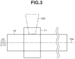
- FIGS. 2A, 2B , and 3 are diagrams illustrating a manufacturing method for the catheter according to the first exemplary embodiment.
- air 12 is injected into the tube 10 in a state where the tube 10 and the cylindrical member 11 are temporarily assembled. Injection of the air 12 expands the tube 10 radially outward, or a direction toward the cylindrical member 11 to bring an outer peripheral surface of the tube 10 into close contact with an inner peripheral surface of the cylindrical member 11. At this time, the air 12 is prevented from leaking out with a sealing member 13 or the like on an opposite side of a side of the tube 10 on which an inlet of the air 12 is disposed.
- a mandrel 14 having a predetermined diameter may be inserted into the tube 10 in a state where the tube 10 and the cylindrical member 11 are temporarily assembled. Insertion of the mandrel 14 expands the tube 10 radially outward, or the direction toward the cylindrical member 11 to bring the outer peripheral surface of the tube 10 into close contact with the inner peripheral surface of the cylindrical member 11.
- the tube 10 and the cylindrical member 11 are laser welded while being rotated with a center 10a of the tube 10 as the center of rotation.
- a laser 100 passes through from a surface (outer peripheral surface) of the cylindrical member 11, melts the outer peripheral surface of the tube 10, and welds it at a contact portion with the cylindrical member 11.
- laser welding is performed while the tube 10 and the cylindrical member 11 are rotated once.
- a shaft may be inserted into the tube 10 (the mandrel 14 may also serve as the shaft), or an outer diameter portion of the tube 10 may be held.
- laser welding may be performed while the laser 100 is being rotated.
- the tube 10 and the cylindrical member 11 are rotated relative to the laser 100.
- An entire width of the cylindrical member 11 is welded, but partial welding may be performed, or welding may be performed with a spot diameter adjusted to the width of the cylindrical member 11, if they are appropriate for weld strength and application.
- an outer diameter R1 of the tube 10 at a portion P 1 to which the cylindrical member 11 is assembled is different from an outer diameter R2 of the tube 10 at a portion P2 where the cylindrical member 11 is not assembled (R1 > R2).
- an outer diameter R of the tube 10 is nearly equal to R2 (R ⁇ R2), and inner diameter r of the cylindrical member 11 is nearly equal to R1 (r ⁇ R1).
- a magnitude relationship therebetween is r (R1) > R (R2).
- a rotation speed of the tube 10 and the cylindrical member 11 is set to 360 rpm as a condition for laser welding.
- a semiconductor laser with a wavelength of 980 nm is used for laser welding, a spot diameter is set to ⁇ 1.0 mm, a laser output is set to 5 W, and a laser irradiation time is set to 20 seconds.
- the conditions for laser welding are not limited to these, and for example, the laser irradiation time may be shortened by increasing the laser output and the rotation speed.
- a second exemplary embodiment is described with reference to Figs. 4 to 9B .
- a cylindrical member 21 is assembled to an outside of a tube 20 by laser welding as in the first exemplary embodiment.
- Dimensions of the tube 20 and the cylindrical member 21 are similar to those of the tube 10 and the cylindrical member 11 according to the first exemplary embodiment.
- Fig. 4 is a perspective view illustrating the catheter according to the second exemplary embodiment.
- a reinforcing member 22 is incorporated in a wall 20b of the tube 20 in order to increase strength.
- stainless steel (SUS304) having a width of 0.07 mm and a thickness of 0.03 mm is interwoven as the reinforcing member 22.
- Fig. 4 illustrates the wall 20b with a surface partially removed for illustration of the reinforcing member 22.
- the strength of the tube 20 is thus increased so that it is difficult to deform the tube 20 by expanding it with the air 12 and/or the mandrel 14, unlike the first exemplary embodiment.
- FIG. 5 is a diagram illustrating the manufacturing method of the catheter according to the second exemplary embodiment.
- the tube 20 and the cylindrical member 21 are laser welded while being rotated with a center 20a of the tube 20 as the center of rotation in a state where the tube 20 and the cylindrical member 21 are temporarily assembled.
- the laser 100 passes through from a surface (outer peripheral surface) of the cylindrical member 21, melts an outer peripheral surface of the tube 20, and welds it at a contact portion with the cylindrical member 21.
- laser welding is performed while the tube 20 and the cylindrical member 21 are rotated a plurality of times.
- the tube 20 and the cylindrical member 21 are rotated, they are fixed by a jig (not illustrated) so that a positional relationship of them is not shifted. That rotation of the tube 20 and the cylindrical member 21 relative to the laser 100 is sufficient, and a welding range are similar to those in the first exemplary embodiment.
- a rotation speed of the tube 20 and the cylindrical member 21 is set to 1800 rpm as a condition for laser welding from a viewpoint described below.
- a semiconductor laser with a wavelength of 980 nm is used for laser welding, a spot diameter is set to ⁇ 1.0 mm, a laser output is set to 16 W, and a laser irradiation time is set to 0.25 seconds.
- a clearance Cb of about 0.04 mm occurs on one side in a state where the tube 20 and the cylindrical member 21 are temporarily assembled.
- the tube 20 and the cylindrical member 21 are welded together due to two phenomena described below.
- a temperature rise at a given position on the tube 20 was estimated when laser welding was performed with the rotation speed of the tube 20 and the cylindrical member 21 changed.
- Fig. 6 is a characteristic diagram in which the horizontal axis represents time S, and the vertical axis represents temperature T at a given position on the tube 20, and illustrates graphs L1 and L2 for different rotation speeds. Preconditions were that a temperature rise in one laser irradiation was set constant (constant heat quantity), and an inclination of cooling was also set constant, assuming heat transfer through the tube 20.
- a temperature of the tube 20 rises and falls repeatedly and reaches a temperature Tm at which the tube 20 melts.
- a time during which the temperature rises with one laser irradiation (t in Fig. 6 ) is defined as a welding time.
- the temperature Tm at which the tube 20 melts is reached at time S1.
- the temperature Tm at which the tube 20 melts is reached at time S2 (> S1).
- the rotation speed is set to 1800 rpm
- the laser irradiation time is set to 0.25 seconds with the graph L1 for a high rotation speed in mind.
- a cooling time (a time from when a certain point is laser-irradiated to when the point is laser-irradiated next) in which the temperature falls is longer if the rotation speed is slower.
- a required heat is higher.
- the required heat is lower.
- Fig. 7 is a diagram illustrating results obtained by verifying whether laser welding is proper or defective, with the rotation speed and the laser output changed and with a multiplication value of the rotation speed and the laser irradiation time (rotation speed ⁇ laser irradiation time) set constant. That the rotation speed ⁇ the laser irradiation time is set constant does not mean that the values are made completely the same, but rather that a certain degree of difference in the values is permitted, and it is sufficient that the values are approximately constant. As illustrated in Fig. 7 , it was found that when the laser welding was performed while the rotation speed and the laser output were being changed with the rotation speed ⁇ the laser irradiation time set constant, a welding defect occurred unless the rotation speed was increased to a certain extent.
- FIG. 8 is a diagram illustrating an influence of the rotation speed. As illustrated in Fig. 8 , it is inferred that the outer peripheral surface of the tube 20 melts, the melted resin is moved outward by centrifugal force, and the heat of the melted resin melts an inner peripheral surface of the cylindrical member 21, resulting in welding. At the rotation speed of 360 rpm, as illustrated in an upper right diagram in Fig.
- a movement amount a1 of the resin gradually melted by the laser 100 was insufficient to fill the clearance Cb, so that the entire circumference was not welded, and even if it was welded, it was only partially.
- a movement amount a2 of the resin gradually melted by the laser 100 is sufficient to fill the clearance Cb.
- a weldable area Z1 can be predicted by verifying whether laser welding is proper or defective with the rotation speed and the laser output being changed with the rotation speed ⁇ laser irradiation time set constant. As described above, at the rotation speed of 1800 rpm, which is set with the graph L1 for a high rotation speed in mind, the weldable area Z 1 falls a range in which the laser output is 14 W or more and 20 W or less.
- Non-weldable areas are roughly classified into a non-weldable area Y1 on a lower laser output side and a non-weldable area Y2 on a high laser output side.
- the tube 20 and the cylindrical member 21 are not welded to each other due to insufficient heat (resin does not melt sufficiently).
- an excess heat state (excessive melting of the resin) may arise to cause a defect as illustrated in Fig. 10B .
- a defect illustrated in Fig. 10C may occur.
- the rotation speed of the tube 20 and the cylindrical member 21 is set in advance such that the conditions within the weldable area Z1 are selected based on the verification results as illustrated in Fig. 7 . If the laser irradiation time or the clearance Cb is changed, the weldable area Z1 and the non-weldable areas Y1 and Y2 each presumably change (shift). In particular, if the clearance Cb is small, it can be inferred that a weldable condition appears even in conditions of a low rotation speed area X1.
- the manufacturing method for a catheter described according to the second exemplary embodiment is also applicable to a case where a reinforcing member is not incorporated.
Landscapes
- Engineering & Computer Science (AREA)
- Physics & Mathematics (AREA)
- Health & Medical Sciences (AREA)
- Mechanical Engineering (AREA)
- Optics & Photonics (AREA)
- Life Sciences & Earth Sciences (AREA)
- Toxicology (AREA)
- Electromagnetism (AREA)
- Surgery (AREA)
- Animal Behavior & Ethology (AREA)
- Veterinary Medicine (AREA)
- Heart & Thoracic Surgery (AREA)
- Biophysics (AREA)
- Biomedical Technology (AREA)
- General Health & Medical Sciences (AREA)
- Public Health (AREA)
- Plasma & Fusion (AREA)
- Nuclear Medicine, Radiotherapy & Molecular Imaging (AREA)
- Pathology (AREA)
- Radiology & Medical Imaging (AREA)
- Molecular Biology (AREA)
- Medical Informatics (AREA)
- Pulmonology (AREA)
- Anesthesiology (AREA)
- Hematology (AREA)
- General Engineering & Computer Science (AREA)
- Manufacturing & Machinery (AREA)
- Fluid Mechanics (AREA)
- Media Introduction/Drainage Providing Device (AREA)
- Lining Or Joining Of Plastics Or The Like (AREA)
Abstract
Description
- The present invention relates to a tube body such as a catheter and a manufacturing method thereof.
- Flexible medical instruments, such as endoscopic surgical instruments and catheters, are known. According to
patent literatures - Laser welding is used to assemble a cylindrical member (e.g., a member referred to as a guide ring) to an outer periphery of a tube main body (e.g., a member referred to as an inner liner or a backbone).
-
- PTL 1:
US No. 9144370 B1 - PTL 2:
WO 2018/204202 A - In assembling a cylindrical member to an outer periphery of a tube main body by laser welding, if there is a clearance between the tube main body and the cylindrical member, an influence of the clearance may induce a welding defect.
- A welding defect between a
tube 110 which is a tube main body and acylindrical member 111 is described with reference toFigs. 10A, 10B, and 10C . - For example, as illustrated in
Fig. 10A , for a clearance that is unevenly present, a welding defect in which thetube 110 and thecylindrical member 111 are only partially welded together. - Further, as illustrated in
Fig. 10B , heat of thetube 110 that is heated by a laser is not transferred to thecylindrical member 111 due to the influence of the clearance, so that thetube 110 is overheat and a welding defect in which ahole 112 is undesirably formed. In particular, a tube for a catheter often has a thin wall thickness (e.g., about 0.25 mm), so that such a welding defect is likely to occur. - Further, as illustrated in
Fig. 10C , in a configuration in which thecylindrical member 111 haswire guide holes 113 with an inner peripheral surface of thecylindrical member 111 and thewire guide holes 113 close to each other, if a laser output is increased (too much heat), the heat of thetube 110 heated by the laser may be excessively transferred to thecylindrical member 111. In this case, a wall between thewire guide hole 113 and thetube 110 melts, and meltedresin 114 of thetube 110 enters thewire guide hole 113 and causes a welding defect in which thewire guide hole 113 is partially or entirely blocked. - The present invention is directed to enabling stable laser welding that is less likely to induce unnecessary welding in consideration of the above-described issues.
- A tube body according to the present invention in which a cylindrical member is assembled to an outer periphery of a tube main body by laser welding, the tube body being characterized in that an outer diameter of the tube main body in a portion where the cylindrical member is assembled is different from an outer diameter of the tube main body in a portion where the cylindrical member is not assembled, and the outer diameter of the tube main body in the portion where the cylindrical member is not assembled is smaller than an inner diameter of the cylindrical member.
- According to the present invention, unnecessary welding is less likely to occur, and stable laser welding is enabled.
-
- [
Fig. 1A] Fig. 1A is a diagram illustrating a catheter according to a first exemplary embodiment. - [
Fig. 1B] Fig. 1B is a diagram illustrating a catheter according to a first exemplary embodiment. - [
Fig. 2A] Fig. 2A is a diagram illustrating a manufacturing method for the catheter according to the first exemplary embodiment. - [
Fig. 2B] Fig. 2B is a diagram illustrating a manufacturing method for the catheter according to the first exemplary embodiment. - [
Fig. 3] Fig. 3 is a diagram illustrating a manufacturing method for the catheter according to the first exemplary embodiment. - [
Fig. 4] Fig. 4 is a diagram illustrating a catheter according to a second exemplary embodiment. - [
Fig. 5] Fig. 5 is a diagram illustrating a manufacturing method for the catheter according to the second exemplary embodiment. - [
Fig. 6] Fig. 6 is a characteristic diagram with time on a horizontal axis and a temperature of a tube on a vertical axis. - [
Fig. 7] Fig. 7 is a diagram illustrating verification results when a rotation speed and a laser output are changed with the rotation speed × a laser irradiation time set constant. - [
Fig. 8] Fig. 8 is a diagram illustrating an influence of a rotation speed. - [
Fig. 9A] Fig. 9A is a diagram illustrating another configuration example of a catheter. - [
Fig. 9B] Fig. 9B is a diagram illustrating another configuration example of a catheter. - [
Fig. 10A] Fig. 10A is a diagram illustrating a welding defect between a tube and a cylindrical member. - [
Fig. 10B] Fig. 10B is a diagram illustrating a welding defect between a tube and a cylindrical member. - [
Fig. 10C] Fig. 10C is a diagram illustrating a welding defect between a tube and a cylindrical member. - Desirable exemplary embodiments of the present invention will be described below with reference to the accompanying drawings.
- A first exemplary embodiment is described with reference to
Figs. 1A to 3 . -
Figs. 1A and 1B are diagrams illustrating a catheter according to the first exemplary embodiment.Fig. 1A is a diagram illustrating atube 10 and acylindrical member 11 before assembly, andFig. 1B is a diagram illustrating thetube 10 and thecylindrical member 11 after assembly. For the catheter, thecylindrical member 11 is assembled to an outside of thetube 10 by laser welding. According to the present exemplary embodiment, the catheter corresponds to a tube body, and thetube 10 corresponds to a tube main body according to the present invention. - Dimensions of the
tube 10 alone are Φ 2.45 mm to 2.49 mm in outer diameter and Φ 2.20 mm to 2.24 mm in inner diameter. Thetube 10 includes about 0.5 to 1.5% carbon black which is a laser absorber. A material of thetube 10 is nylon-based synthetic resin. - Dimensions of the cylindrical member 11a alone are Φ 3.67 mm to 3.75 mm in outer diameter and Φ 2.50 mm to 2.55 mm in inner diameter. The
cylindrical member 11 is transparent so that laser can pass through it. A material of thecylindrical member 11 is nylon-based synthetic resin. - A clearance of about 0.005 mm to 0.05 mm occurs on one side in a state where the
tube 10 and thecylindrical member 11 having a dimensional relationship described above are temporarily assembled. - As illustrated in
Fig. 1A , for reasons that thecylindrical member 11 is assembled from an end direction of thetube 10, an outer diameter R of thetube 10 and an inner diameter r of thecylindrical member 11 have a relationship of R < r. It is desirable to bring thetube 10 and thecylindrical member 11 into close contact with each other for laser welding, but if r = R, it is difficult to assemble thecylindrical member 11 to thetube 10. Even if they can be assembled, a defect may occur in a product such as deformation in thetube 10. Thus, after thetube 10 and thecylindrical member 11 are temporarily assembled, thetube 10 and thecylindrical member 11 are to be brought into close contact with each other. - A manufacturing method for a catheter is described below with reference to
Figs. 2A, 2B , and3 .Figs. 2A, 2B , and3 are diagrams illustrating a manufacturing method for the catheter according to the first exemplary embodiment. - As illustrated in
Fig. 2A , in a case where thetube 10 is made of a material that has an elastic characteristic, such as rubber,air 12 is injected into thetube 10 in a state where thetube 10 and thecylindrical member 11 are temporarily assembled. Injection of theair 12 expands thetube 10 radially outward, or a direction toward thecylindrical member 11 to bring an outer peripheral surface of thetube 10 into close contact with an inner peripheral surface of thecylindrical member 11. At this time, theair 12 is prevented from leaking out with a sealingmember 13 or the like on an opposite side of a side of thetube 10 on which an inlet of theair 12 is disposed. - Further, as illustrated in
Fig. 2B , amandrel 14 having a predetermined diameter may be inserted into thetube 10 in a state where thetube 10 and thecylindrical member 11 are temporarily assembled. Insertion of themandrel 14 expands thetube 10 radially outward, or the direction toward thecylindrical member 11 to bring the outer peripheral surface of thetube 10 into close contact with the inner peripheral surface of thecylindrical member 11. - Next, as illustrated in
Fig. 3 , thetube 10 and thecylindrical member 11 are laser welded while being rotated with acenter 10a of thetube 10 as the center of rotation. Alaser 100 passes through from a surface (outer peripheral surface) of thecylindrical member 11, melts the outer peripheral surface of thetube 10, and welds it at a contact portion with thecylindrical member 11. According to the present exemplary embodiment, laser welding is performed while thetube 10 and thecylindrical member 11 are rotated once. When thetube 10 and thecylindrical member 11 are rotated, a shaft may be inserted into the tube 10 (themandrel 14 may also serve as the shaft), or an outer diameter portion of thetube 10 may be held. Instead of rotating thetube 10 and thecylindrical member 11, laser welding may be performed while thelaser 100 is being rotated. In other words, it is sufficient that thetube 10 and thecylindrical member 11 are rotated relative to thelaser 100. An entire width of thecylindrical member 11 is welded, but partial welding may be performed, or welding may be performed with a spot diameter adjusted to the width of thecylindrical member 11, if they are appropriate for weld strength and application. - Next, the
air 12 and/or themandrel 14 used for bringing thetube 10 and thecylindrical member 11 into close contact with each other is/are removed. This returns a portion having not been welded to thecylindrical member 11 to its original state, and the catheter which is a product is completed as illustrated inFig. 1B . In the catheter, an outer diameter R1 of thetube 10 at aportion P 1 to which thecylindrical member 11 is assembled is different from an outer diameter R2 of thetube 10 at a portion P2 where thecylindrical member 11 is not assembled (R1 > R2). In addition, an outer diameter R of thetube 10 is nearly equal to R2 (R ≈ R2), and inner diameter r of thecylindrical member 11 is nearly equal to R1 (r ≈ R1). Thus, a magnitude relationship therebetween is r (R1) > R (R2). - According to the first exemplary embodiment, a rotation speed of the
tube 10 and thecylindrical member 11 is set to 360 rpm as a condition for laser welding. In addition, a semiconductor laser with a wavelength of 980 nm is used for laser welding, a spot diameter is set to Φ 1.0 mm, a laser output is set to 5 W, and a laser irradiation time is set to 20 seconds. The conditions for laser welding are not limited to these, and for example, the laser irradiation time may be shortened by increasing the laser output and the rotation speed. - According to the first exemplary embodiment as described above, since laser welding is performed with the
tube 10 in a close contact with thecylindrical member 11, unnecessary welding is less likely to occur, and stable laser welding is enabled. - A second exemplary embodiment is described with reference to
Figs. 4 to 9B . For a catheter according to the second exemplary embodiment, acylindrical member 21 is assembled to an outside of atube 20 by laser welding as in the first exemplary embodiment. Dimensions of thetube 20 and thecylindrical member 21 are similar to those of thetube 10 and thecylindrical member 11 according to the first exemplary embodiment. -
Fig. 4 is a perspective view illustrating the catheter according to the second exemplary embodiment. According to the second exemplary embodiment, a reinforcingmember 22 is incorporated in awall 20b of thetube 20 in order to increase strength. For example, stainless steel (SUS304) having a width of 0.07 mm and a thickness of 0.03 mm is interwoven as the reinforcingmember 22.Fig. 4 illustrates thewall 20b with a surface partially removed for illustration of the reinforcingmember 22. - The strength of the
tube 20 is thus increased so that it is difficult to deform thetube 20 by expanding it with theair 12 and/or themandrel 14, unlike the first exemplary embodiment. - A manufacturing method for the catheter is described below with reference to
Figs. 5 ,9A , and9B .Fig. 5 is a diagram illustrating the manufacturing method of the catheter according to the second exemplary embodiment. - According to the second exemplary embodiment, as illustrated in
Fig. 5 , thetube 20 and thecylindrical member 21 are laser welded while being rotated with acenter 20a of thetube 20 as the center of rotation in a state where thetube 20 and thecylindrical member 21 are temporarily assembled. Thelaser 100 passes through from a surface (outer peripheral surface) of thecylindrical member 21, melts an outer peripheral surface of thetube 20, and welds it at a contact portion with thecylindrical member 21. According to the present exemplary embodiment, laser welding is performed while thetube 20 and thecylindrical member 21 are rotated a plurality of times. When thetube 20 and thecylindrical member 21 are rotated, they are fixed by a jig (not illustrated) so that a positional relationship of them is not shifted. That rotation of thetube 20 and thecylindrical member 21 relative to thelaser 100 is sufficient, and a welding range are similar to those in the first exemplary embodiment. - According to the second exemplary embodiment, a rotation speed of the
tube 20 and thecylindrical member 21 is set to 1800 rpm as a condition for laser welding from a viewpoint described below. In addition, a semiconductor laser with a wavelength of 980 nm is used for laser welding, a spot diameter is set to Φ 1.0 mm, a laser output is set to 16 W, and a laser irradiation time is set to 0.25 seconds. - As illustrated in
Fig. 5 , a clearance Cb of about 0.04 mm occurs on one side in a state where thetube 20 and thecylindrical member 21 are temporarily assembled. - According to the second exemplary embodiment, it can be said that the
tube 20 and thecylindrical member 21 are welded together due to two phenomena described below. - As in the first exemplary embodiment, if the outer peripheral surface of the
tube 10 is in close contact with the inner peripheral surface of thecylindrical member 11, laser welding can be performed while thetube 10 and thecylindrical member 11 are rotated once. - However, if there is the clearance Cb between the
tube 20 and thecylindrical member 21 as in the second exemplary embodiment, heat obtained by melting the outer peripheral surface of thetube 20 is not easily transferred to thecylindrical member 21, and welding is difficult. Thus, it is desirable that the outer peripheral surface of thetube 20 is gradually melted so as to achieve a state where the melted resin fills the clearance Cb. In order to achieve this, thetube 10 and thecylindrical member 11 are laser welded while being rotated a plurality of times so that instantaneous heat is applied a plurality of times. - Thus, a temperature rise at a given position on the
tube 20 was estimated when laser welding was performed with the rotation speed of thetube 20 and thecylindrical member 21 changed.Fig. 6 is a characteristic diagram in which the horizontal axis represents time S, and the vertical axis represents temperature T at a given position on thetube 20, and illustrates graphs L1 and L2 for different rotation speeds. Preconditions were that a temperature rise in one laser irradiation was set constant (constant heat quantity), and an inclination of cooling was also set constant, assuming heat transfer through thetube 20. - As illustrated in
Fig. 6 , a temperature of thetube 20 rises and falls repeatedly and reaches a temperature Tm at which thetube 20 melts. A time during which the temperature rises with one laser irradiation (t inFig. 6 ) is defined as a welding time. In the graph L1 for a high rotation speed, the temperature Tm at which thetube 20 melts is reached at time S1. In contrast, in the graph L2 for a low rotation speed, the temperature Tm at which thetube 20 melts is reached at time S2 (> S1). In a case where it takes a long time to reach the temperature Tm at which the tube melts, influences of other factors (convection and heat dissipation into the air) are to be considered. Thus, according to the present exemplary embodiment, the rotation speed is set to 1800 rpm, and the laser irradiation time is set to 0.25 seconds with the graph L1 for a high rotation speed in mind. - Here, as illustrated in
Fig. 6 , a cooling time (a time from when a certain point is laser-irradiated to when the point is laser-irradiated next) in which the temperature falls is longer if the rotation speed is slower. Thus, as the rotation speed is slower, a required heat is higher. In other words, as the rotation speed is faster, the required heat is lower. A total heat quantity in a case where the rotation speed is 1800 rpm and the laser output is 16 W is set to "laser irradiation time 0.25 s × laser output 16 W =total heat quantity 4". If this is considered to be the center, when the rotation speed < 1800 rpm is satisfied, the cooling time increases, so that the total heat quantity > 4 is set, whereas when the rotation speed > 1800 rpm is satisfied, the cooling time decreases, so that the total heat quantity < 4 is set. In this manner, the rotation speed of thetube 20 and thecylindrical member 21 is set in a relationship in which as the rotation speed is higher, the total heat quantity is lower. - An influence of the rotation speed of the
tube 20 and thecylindrical member 21 was examined. -
Fig. 7 is a diagram illustrating results obtained by verifying whether laser welding is proper or defective, with the rotation speed and the laser output changed and with a multiplication value of the rotation speed and the laser irradiation time (rotation speed × laser irradiation time) set constant. That the rotation speed × the laser irradiation time is set constant does not mean that the values are made completely the same, but rather that a certain degree of difference in the values is permitted, and it is sufficient that the values are approximately constant. As illustrated inFig. 7 , it was found that when the laser welding was performed while the rotation speed and the laser output were being changed with the rotation speed × the laser irradiation time set constant, a welding defect occurred unless the rotation speed was increased to a certain extent. - At the rotation speed of 360 rpm, even if the laser output was increased, a welding defect as illustrated in
Fig. 10A occurred. Then, a condition where no welding defect occurs appeared at the rotation speed of 720 rpm or more.Fig. 8 is a diagram illustrating an influence of the rotation speed. As illustrated inFig. 8 , it is inferred that the outer peripheral surface of thetube 20 melts, the melted resin is moved outward by centrifugal force, and the heat of the melted resin melts an inner peripheral surface of thecylindrical member 21, resulting in welding. At the rotation speed of 360 rpm, as illustrated in an upper right diagram inFig. 8 , a movement amount a1 of the resin gradually melted by thelaser 100 was insufficient to fill the clearance Cb, so that the entire circumference was not welded, and even if it was welded, it was only partially. In contrast, at the rotation speed of 720 rpm or more, as illustrated in a lower right diagram inFig. 8 , it can be said that a movement amount a2 of the resin gradually melted by thelaser 100 is sufficient to fill the clearance Cb. - As illustrated in
Fig. 7 , a weldable area Z1 can be predicted by verifying whether laser welding is proper or defective with the rotation speed and the laser output being changed with the rotation speed × laser irradiation time set constant. As described above, at the rotation speed of 1800 rpm, which is set with the graph L1 for a high rotation speed in mind, theweldable area Z 1 falls a range in which the laser output is 14 W or more and 20 W or less. - Non-weldable areas are roughly classified into a non-weldable area Y1 on a lower laser output side and a non-weldable area Y2 on a high laser output side. In the non-weldable area Y1, the
tube 20 and thecylindrical member 21 are not welded to each other due to insufficient heat (resin does not melt sufficiently). In contrast, in the non-weldable area Y2, an excess heat state (excessive melting of the resin) may arise to cause a defect as illustrated inFig. 10B . Further, if there is a wire guide hole in thecylindrical member 21, a defect illustrated inFig. 10C may occur. - As described above, the rotation speed of the
tube 20 and thecylindrical member 21 is set in advance such that the conditions within the weldable area Z1 are selected based on the verification results as illustrated inFig. 7 . If the laser irradiation time or the clearance Cb is changed, the weldable area Z1 and the non-weldable areas Y1 and Y2 each presumably change (shift). In particular, if the clearance Cb is small, it can be inferred that a weldable condition appears even in conditions of a low rotation speed area X1. - According to the second exemplary embodiment as described above, even if there is a clearance between the
tube 20 and thecylindrical member 21, unnecessary welding is less likely to occur and stable laser welding can be performed by the rotation speed and the laser output appropriately set. - Even in a case where a plurality of
cylindrical members 31a to 31e (in various clearance relationships) is assembled outside atube 30 by laser welding as illustrated inFigs. 9A and9B , application of the present exemplary embodiment makes unnecessary welding less likely to occur, thus enabling stable laser welding. - According to the second exemplary embodiment, an example targeted at a catheter incorporating a reinforcing member has been described, but the manufacturing method for a catheter described according to the second exemplary embodiment is also applicable to a case where a reinforcing member is not incorporated.
- The present invention is described above together with the exemplary embodiments, but the above-described exemplary embodiments are merely examples for implementing the present invention, so that the exemplary embodiments should not be construed restrictively limiting the technical scope of the present invention. In other words, the present invention can be implemented in the various forms without departing from the technical idea or the main features thereof. For example, the numerical values described in the exemplary embodiments are for reference numerical values and do not limit the present invention.
- The present invention is not limited to the above-described exemplary embodiments, and various modifications and changes can be made without departing from the spirit and the scope of the present invention. Therefore, the following claims are attached in order to publicize the scope of the present invention.
- This application claims priority based on
Japanese Patent Application No. 2022-029374 filed on February 28, 2022 -
- 10, 20, 30 Tube
- 11, 21, 31a to 31e Cylindrical member
- 12 Air
- 14 Mandrel
- 100 Laser
Claims (7)
- A tube body in which a cylindrical member assembled to an outer periphery of a tube main body by laser welding, the tube body being characterized in that an outer diameter of the tube main body in a portion where the cylindrical member is assembled is different from an outer diameter of the tube main body in a portion where the cylindrical member is not assembled, and the outer diameter of the tube main body in the portion where the cylindrical member is not assembled is smaller than an inner diameter of the cylindrical member.
- The tube body according to Claim 1, wherein a reinforcing member is incorporated in a wall of the tube main body.
- A method for manufacturing the tube body according to Claim 1, the method being characterized in that the cylindrical member is temporarily assembled to the outer periphery of the tube main body, air is injected into the tube main body to bring the tube main body into close contact with the cylindrical member, and laser welding is performed.
- A method for manufacturing the tube body according to Claim 1, the method being characterized in that the cylindrical member is temporarily assembled to the outer periphery of the tube main body, a mandrel is inserted into the tube main body to bring the tube main body into close contact with the cylindrical member, and laser welding is performed.
- A method for manufacturing the tube body according to Claim 1 or 2, the method being characterized in that the cylindrical member is temporarily assembled to the outer periphery of the tube main body, and laser welding is performed while the tube main body and the cylindrical member, and laser are rotated relative to each other at a predetermined rotation speed for a plurality of rotations with a center of the tube main body serving as a center of rotation.
- The method for manufacturing the tube body according to Claim 5, wherein the predetermined rotation speed is set in advance based on a result obtained by verifying whether laser welding is proper or defective with a rotation speed and laser output changed and with a multiplication value of the rotation speed and a laser irradiation time set constant.
- The method for manufacturing the tube body according to Claim 5 or 6,wherein a multiplication value of a laser irradiation time and laser output is regarded as a total heat quantity, andwherein the predetermined rotation speed is set in a relationship in which as the rotation speed is faster, the total heat quantity is lower.
Applications Claiming Priority (2)
| Application Number | Priority Date | Filing Date | Title |
|---|---|---|---|
| JP2022029374A JP2023125343A (en) | 2022-02-28 | 2022-02-28 | Tube and its manufacturing method |
| PCT/JP2023/004493 WO2023162711A1 (en) | 2022-02-28 | 2023-02-10 | Tubular object and production method therefor |
Publications (2)
| Publication Number | Publication Date |
|---|---|
| EP4488041A1 true EP4488041A1 (en) | 2025-01-08 |
| EP4488041A4 EP4488041A4 (en) | 2026-03-18 |
Family
ID=87765724
Family Applications (1)
| Application Number | Title | Priority Date | Filing Date |
|---|---|---|---|
| EP23759715.8A Pending EP4488041A4 (en) | 2022-02-28 | 2023-02-10 | TUBE-SHAPED OBJECT AND MANUFACTURING METHOD FOR IT |
Country Status (4)
| Country | Link |
|---|---|
| US (1) | US20240407633A1 (en) |
| EP (1) | EP4488041A4 (en) |
| JP (1) | JP2023125343A (en) |
| WO (1) | WO2023162711A1 (en) |
Family Cites Families (11)
| Publication number | Priority date | Publication date | Assignee | Title |
|---|---|---|---|---|
| US4650110A (en) * | 1985-10-22 | 1987-03-17 | Westinghouse Electric Corp. | Continuous movement brazing process |
| US4694136A (en) * | 1986-01-23 | 1987-09-15 | Westinghouse Electric Corp. | Laser welding of a sleeve within a tube |
| JPH08303646A (en) * | 1995-05-08 | 1996-11-22 | Futaba Sangyo Kk | Pipe with u-bolt |
| JP4614480B2 (en) * | 1999-05-19 | 2011-01-19 | 光陽産業株式会社 | Non-rotating device for pressure regulator |
| JP2009083406A (en) * | 2007-10-02 | 2009-04-23 | Kawano:Kk | Pipe joining method |
| JP5772152B2 (en) * | 2011-03-31 | 2015-09-02 | 株式会社ジェイ・エム・エス | Medical connecting member and manufacturing method thereof |
| US9144370B2 (en) | 2013-02-28 | 2015-09-29 | Canon Usa Inc. | Mechanical structure of articulated sheath |
| JP7609880B2 (en) * | 2020-02-21 | 2025-01-07 | キヤノン ユーエスエイ,インコーポレイテッド | Laser welding of plastics for steerable catheter tips |
| JP2022029374A (en) | 2020-08-04 | 2022-02-17 | 大日本印刷株式会社 | Article having rf tag and mounting method of article having rf tag |
| CN112643204B (en) * | 2020-12-01 | 2022-10-28 | 东方电气集团东方锅炉股份有限公司 | Laser tube plate welding process suitable for flush type and strength welding |
| CN113370259B (en) * | 2021-06-04 | 2023-01-20 | 青岛海泰新光科技股份有限公司 | Fluid locking mechanical arm |
-
2022
- 2022-02-28 JP JP2022029374A patent/JP2023125343A/en active Pending
-
2023
- 2023-02-10 EP EP23759715.8A patent/EP4488041A4/en active Pending
- 2023-02-10 WO PCT/JP2023/004493 patent/WO2023162711A1/en not_active Ceased
-
2024
- 2024-08-23 US US18/813,746 patent/US20240407633A1/en active Pending
Also Published As
| Publication number | Publication date |
|---|---|
| WO2023162711A1 (en) | 2023-08-31 |
| JP2023125343A (en) | 2023-09-07 |
| US20240407633A1 (en) | 2024-12-12 |
| EP4488041A4 (en) | 2026-03-18 |
Similar Documents
| Publication | Publication Date | Title |
|---|---|---|
| JP5469680B2 (en) | Catheter with skive-like tubular member | |
| EP2840315B1 (en) | Glow plug with pressure sensor and method of manufacturing | |
| JPH0852805A (en) | Welding method of plastic pipe and socket used for this | |
| JP6164638B2 (en) | Balloon catheter | |
| JP6542447B1 (en) | Method and structure for joining resin pipe and resin member | |
| EP4488041A1 (en) | Tubular object and production method therefor | |
| US20110315299A1 (en) | Pipe arrangement | |
| JP5555531B2 (en) | Welded joint and welding method thereof | |
| US5990462A (en) | Welding collar | |
| JP5580279B2 (en) | Balloon catheter | |
| TWI821261B (en) | Manufacturing method of resin piping, and resin piping | |
| CN118787845A (en) | Balloon catheter and method for manufacturing the same | |
| JP7583785B2 (en) | Medical shaft, medical device, and method for manufacturing medical shaft | |
| CN118615562A (en) | A balloon guide catheter | |
| TW201905373A (en) | Resin pipe member, resin pipe member manufacturing method, resin pipe joint, and resin pipe | |
| JP2024178822A (en) | Manufacturing method of bush | |
| JP2004358308A (en) | Painting roller | |
| JP5173571B2 (en) | Electrofusion fitting | |
| CN110475659B (en) | Hot riveting device | |
| JPH11280978A (en) | Electric fusion coupling | |
| JP2018083323A (en) | Resin-made assembly and manufacturing method of resin-made assembly | |
| JPH11294673A (en) | Electrofusion joint | |
| JP2022133599A (en) | Medical needle and manufacturing method thereof | |
| JP2026051604A (en) | Resin fittings, connection structures, and connection methods | |
| JP3636354B2 (en) | Electric fusion type plastic pipe fittings |
Legal Events
| Date | Code | Title | Description |
|---|---|---|---|
| STAA | Information on the status of an ep patent application or granted ep patent |
Free format text: STATUS: THE INTERNATIONAL PUBLICATION HAS BEEN MADE |
|
| PUAI | Public reference made under article 153(3) epc to a published international application that has entered the european phase |
Free format text: ORIGINAL CODE: 0009012 |
|
| STAA | Information on the status of an ep patent application or granted ep patent |
Free format text: STATUS: REQUEST FOR EXAMINATION WAS MADE |
|
| 17P | Request for examination filed |
Effective date: 20240930 |
|
| AK | Designated contracting states |
Kind code of ref document: A1 Designated state(s): AL AT BE BG CH CY CZ DE DK EE ES FI FR GB GR HR HU IE IS IT LI LT LU LV MC ME MK MT NL NO PL PT RO RS SE SI SK SM TR |
|
| DAV | Request for validation of the european patent (deleted) | ||
| DAX | Request for extension of the european patent (deleted) | ||
| A4 | Supplementary search report drawn up and despatched |
Effective date: 20260216 |
|
| RIC1 | Information provided on ipc code assigned before grant |
Ipc: B29C 65/16 20060101AFI20260210BHEP Ipc: F16L 47/30 20060101ALI20260210BHEP |