EP4488035A1 - Shaping method and shaping device - Google Patents
Shaping method and shaping device Download PDFInfo
- Publication number
- EP4488035A1 EP4488035A1 EP22929814.6A EP22929814A EP4488035A1 EP 4488035 A1 EP4488035 A1 EP 4488035A1 EP 22929814 A EP22929814 A EP 22929814A EP 4488035 A1 EP4488035 A1 EP 4488035A1
- Authority
- EP
- European Patent Office
- Prior art keywords
- flattening
- layer
- discharging
- semi
- curing
- Prior art date
- Legal status (The legal status is an assumption and is not a legal conclusion. Google has not performed a legal analysis and makes no representation as to the accuracy of the status listed.)
- Granted
Links
Images



Classifications
-
- B—PERFORMING OPERATIONS; TRANSPORTING
- B29—WORKING OF PLASTICS; WORKING OF SUBSTANCES IN A PLASTIC STATE IN GENERAL
- B29C—SHAPING OR JOINING OF PLASTICS; SHAPING OF MATERIAL IN A PLASTIC STATE, NOT OTHERWISE PROVIDED FOR; AFTER-TREATMENT OF THE SHAPED PRODUCTS, e.g. REPAIRING
- B29C64/00—Additive manufacturing, i.e. manufacturing of three-dimensional [3D] objects by additive deposition, additive agglomeration or additive layering, e.g. by 3D printing, stereolithography or selective laser sintering
- B29C64/10—Processes of additive manufacturing
- B29C64/188—Processes of additive manufacturing involving additional operations performed on the added layers, e.g. smoothing, grinding or thickness control
- B29C64/194—Processes of additive manufacturing involving additional operations performed on the added layers, e.g. smoothing, grinding or thickness control during lay-up
-
- B—PERFORMING OPERATIONS; TRANSPORTING
- B22—CASTING; POWDER METALLURGY
- B22F—WORKING METALLIC POWDER; MANUFACTURE OF ARTICLES FROM METALLIC POWDER; MAKING METALLIC POWDER; APPARATUS OR DEVICES SPECIALLY ADAPTED FOR METALLIC POWDER
- B22F10/00—Additive manufacturing of workpieces or articles from metallic powder
- B22F10/10—Formation of a green body
-
- B—PERFORMING OPERATIONS; TRANSPORTING
- B22—CASTING; POWDER METALLURGY
- B22F—WORKING METALLIC POWDER; MANUFACTURE OF ARTICLES FROM METALLIC POWDER; MAKING METALLIC POWDER; APPARATUS OR DEVICES SPECIALLY ADAPTED FOR METALLIC POWDER
- B22F10/00—Additive manufacturing of workpieces or articles from metallic powder
- B22F10/30—Process control
- B22F10/37—Process control of powder bed aspects, e.g. density
-
- B—PERFORMING OPERATIONS; TRANSPORTING
- B22—CASTING; POWDER METALLURGY
- B22F—WORKING METALLIC POWDER; MANUFACTURE OF ARTICLES FROM METALLIC POWDER; MAKING METALLIC POWDER; APPARATUS OR DEVICES SPECIALLY ADAPTED FOR METALLIC POWDER
- B22F10/00—Additive manufacturing of workpieces or articles from metallic powder
- B22F10/30—Process control
- B22F10/38—Process control to achieve specific product aspects, e.g. surface smoothness, density, porosity or hollow structures
-
- B—PERFORMING OPERATIONS; TRANSPORTING
- B22—CASTING; POWDER METALLURGY
- B22F—WORKING METALLIC POWDER; MANUFACTURE OF ARTICLES FROM METALLIC POWDER; MAKING METALLIC POWDER; APPARATUS OR DEVICES SPECIALLY ADAPTED FOR METALLIC POWDER
- B22F12/00—Apparatus or devices specially adapted for additive manufacturing; Auxiliary means for additive manufacturing; Combinations of additive manufacturing apparatus or devices with other processing apparatus or devices
- B22F12/60—Planarisation devices; Compression devices
- B22F12/63—Rollers
-
- B—PERFORMING OPERATIONS; TRANSPORTING
- B22—CASTING; POWDER METALLURGY
- B22F—WORKING METALLIC POWDER; MANUFACTURE OF ARTICLES FROM METALLIC POWDER; MAKING METALLIC POWDER; APPARATUS OR DEVICES SPECIALLY ADAPTED FOR METALLIC POWDER
- B22F7/00—Manufacture of composite layers, workpieces, or articles, comprising metallic powder, by sintering the powder, with or without compacting wherein at least one part is obtained by sintering or compression
- B22F7/06—Manufacture of composite layers, workpieces, or articles, comprising metallic powder, by sintering the powder, with or without compacting wherein at least one part is obtained by sintering or compression of composite workpieces or articles from parts, e.g. to form tipped tools
-
- B—PERFORMING OPERATIONS; TRANSPORTING
- B29—WORKING OF PLASTICS; WORKING OF SUBSTANCES IN A PLASTIC STATE IN GENERAL
- B29C—SHAPING OR JOINING OF PLASTICS; SHAPING OF MATERIAL IN A PLASTIC STATE, NOT OTHERWISE PROVIDED FOR; AFTER-TREATMENT OF THE SHAPED PRODUCTS, e.g. REPAIRING
- B29C64/00—Additive manufacturing, i.e. manufacturing of three-dimensional [3D] objects by additive deposition, additive agglomeration or additive layering, e.g. by 3D printing, stereolithography or selective laser sintering
- B29C64/10—Processes of additive manufacturing
- B29C64/106—Processes of additive manufacturing using only liquids or viscous materials, e.g. depositing a continuous bead of viscous material
- B29C64/112—Processes of additive manufacturing using only liquids or viscous materials, e.g. depositing a continuous bead of viscous material using individual droplets, e.g. from jetting heads
-
- B—PERFORMING OPERATIONS; TRANSPORTING
- B29—WORKING OF PLASTICS; WORKING OF SUBSTANCES IN A PLASTIC STATE IN GENERAL
- B29C—SHAPING OR JOINING OF PLASTICS; SHAPING OF MATERIAL IN A PLASTIC STATE, NOT OTHERWISE PROVIDED FOR; AFTER-TREATMENT OF THE SHAPED PRODUCTS, e.g. REPAIRING
- B29C64/00—Additive manufacturing, i.e. manufacturing of three-dimensional [3D] objects by additive deposition, additive agglomeration or additive layering, e.g. by 3D printing, stereolithography or selective laser sintering
- B29C64/10—Processes of additive manufacturing
- B29C64/106—Processes of additive manufacturing using only liquids or viscous materials, e.g. depositing a continuous bead of viscous material
- B29C64/124—Processes of additive manufacturing using only liquids or viscous materials, e.g. depositing a continuous bead of viscous material using layers of liquid which are selectively solidified
-
- B—PERFORMING OPERATIONS; TRANSPORTING
- B29—WORKING OF PLASTICS; WORKING OF SUBSTANCES IN A PLASTIC STATE IN GENERAL
- B29C—SHAPING OR JOINING OF PLASTICS; SHAPING OF MATERIAL IN A PLASTIC STATE, NOT OTHERWISE PROVIDED FOR; AFTER-TREATMENT OF THE SHAPED PRODUCTS, e.g. REPAIRING
- B29C64/00—Additive manufacturing, i.e. manufacturing of three-dimensional [3D] objects by additive deposition, additive agglomeration or additive layering, e.g. by 3D printing, stereolithography or selective laser sintering
- B29C64/20—Apparatus for additive manufacturing; Details thereof or accessories therefor
- B29C64/205—Means for applying layers
- B29C64/218—Rollers
-
- H—ELECTRICITY
- H05—ELECTRIC TECHNIQUES NOT OTHERWISE PROVIDED FOR
- H05K—PRINTED CIRCUITS; CASINGS OR CONSTRUCTIONAL DETAILS OF ELECTRIC APPARATUS; MANUFACTURE OF ASSEMBLAGES OF ELECTRICAL COMPONENTS
- H05K3/00—Apparatus or processes for manufacturing printed circuits
- H05K3/10—Apparatus or processes for manufacturing printed circuits in which conductive material is applied to the insulating support in such a manner as to form the desired conductive pattern
-
- B—PERFORMING OPERATIONS; TRANSPORTING
- B33—ADDITIVE MANUFACTURING TECHNOLOGY
- B33Y—ADDITIVE MANUFACTURING, i.e. MANUFACTURING OF THREE-DIMENSIONAL [3D] OBJECTS BY ADDITIVE DEPOSITION, ADDITIVE AGGLOMERATION OR ADDITIVE LAYERING, e.g. BY 3D PRINTING, STEREOLITHOGRAPHY OR SELECTIVE LASER SINTERING
- B33Y10/00—Processes of additive manufacturing
-
- B—PERFORMING OPERATIONS; TRANSPORTING
- B33—ADDITIVE MANUFACTURING TECHNOLOGY
- B33Y—ADDITIVE MANUFACTURING, i.e. MANUFACTURING OF THREE-DIMENSIONAL [3D] OBJECTS BY ADDITIVE DEPOSITION, ADDITIVE AGGLOMERATION OR ADDITIVE LAYERING, e.g. BY 3D PRINTING, STEREOLITHOGRAPHY OR SELECTIVE LASER SINTERING
- B33Y30/00—Apparatus for additive manufacturing; Details thereof or accessories therefor
-
- B—PERFORMING OPERATIONS; TRANSPORTING
- B33—ADDITIVE MANUFACTURING TECHNOLOGY
- B33Y—ADDITIVE MANUFACTURING, i.e. MANUFACTURING OF THREE-DIMENSIONAL [3D] OBJECTS BY ADDITIVE DEPOSITION, ADDITIVE AGGLOMERATION OR ADDITIVE LAYERING, e.g. BY 3D PRINTING, STEREOLITHOGRAPHY OR SELECTIVE LASER SINTERING
- B33Y40/00—Auxiliary operations or equipment, e.g. for material handling
Definitions
- the present disclosure relates to a shaping method and a shaping device that perform shaping using curable viscous fluid.
- curable viscous fluid such as an ultraviolet curing resin
- curable viscous fluid is discharged by a discharging device
- the discharged curable viscous fluid is cured by irradiation with ultraviolet rays
- a desired shaped object is shaped with a cured layer that has been cured.
- Patent Literature 1 a first unit layer to which an ultraviolet curing resin has been discharged is semi-cured by irradiating the first unit layer with ultraviolet rays, and a flattening process of the first unit layer is performed by a flattening roller unit.
- Patent Literature 1 JP-A-2018-114657
- a locally raised portion may be formed by a surface tension of the ultraviolet curing resin.
- an end portion of the shaped object or a central portion of the shaped object having a small width of several mm or less becomes higher than a target height in the design data due to the surface tension.
- a shape of an upper layer and a shape of a shaped object of a finished product may be affected by the locally raised portion.
- the present disclosure has been made in view of such circumstances, and an object thereof is to provide a shaping method and a shaping device capable of reducing an influence of a raised portion of a semi-cured layer on an upper layer.
- a shaping method including: a first discharging step of discharging first curable viscous fluid from above a stage; a first flattening step of flattening the first curable viscous fluid discharged in the first discharging step by a flattening member; a first curing step of curing the first curable viscous fluid flattened in the first flattening step; a first flattening layer forming step of forming a first flattening layer on the stage by repeatedly executing the first discharging step, the first flattening step, and the first curing step; a second discharging step of discharging second curable viscous fluid from above the stage; a semi-curing step of semi-curing the second curable viscous fluid discharged in the second discharging step; a semi-cured layer forming step of forming a semi-cured layer on the stage by repeatedly executing the second discharging step and the semi-curing step;
- the content of the present disclosure is not limited to being implemented as the shaping method, and it is extremely effective to be implemented as a shaping device including a discharging device, a roller, a curing device, and a control device.
- the flattening member when the first curable viscous fluid discharged onto the smooth layer is flattened, the flattening member is disposed at the height corresponding to the height of the raised portion of the smooth layer to flatten the first curable viscous fluid.
- the flattening can be performed by bringing the flattening member into contact with the first curable viscous fluid discharged onto the raised portion while avoiding interference between the raised portion and the flattening member.
- the total time during which the first curable viscous fluid discharged onto the raised portion and the flattening member are in contact with each other can be increased, and by removing the excess first curable viscous fluid, an increase in the raised portion can be suppressed.
- the influence of the raised portion of the smooth layer obtained by curing the semi-cured layer on an upper layer can be reduced.
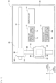
- Fig. 1 illustrates shaping device 10 according to the present embodiment.
- shaping device 10 includes conveyance device 20, shaping unit 22, mounting unit 23, inspection unit 24, and control device 26 (refer to Fig. 2 ).
- Conveyance device 20, shaping unit 22, mounting unit 23, and inspection unit 24 are disposed on base 28 of shaping device 10.
- Base 28 generally has a rectangular shape.
- a longitudinal direction of base 28 will be referred to as an X-axis direction
- a transverse direction of base 28 will be referred to as a Y-axis direction
- a direction orthogonal to both the X-axis direction and the Y-axis direction will be referred to as a Z-axis direction.
- Conveyance device 20 includes X-axis slide mechanism 30 and Y-axis slide mechanism 32.
- X-axis slide mechanism 30 includes X-axis slide rail 34 and X-axis slider 36.
- X-axis slide rail 34 is disposed on base 28 to extend in the X-axis direction.
- X-axis slider 36 is held by X-axis slide rail 34 to be slidable in the X-axis direction.
- X-axis slide mechanism 30 includes electromagnetic motor 38 (refer to Fig. 2 ) and moves X-axis slider 36 to any position in the X-axis direction by driving electromagnetic motor 38.
- Y-axis slide mechanism 32 includes Y-axis slide rail 50 and stage 52.
- Y-axis slide rail 50 is disposed to extend in the Y-axis direction on base 28.
- One end portion of Y-axis slide rail 50 in the Y-axis direction is coupled to X-axis slider 36. Consequently, Y-axis slide rail 50 is configured to be movable in the X-axis direction in accordance with sliding movement of X-axis slider 36.
- Stage 52 is held to be slidable in the Y-axis direction by Y-axis slide rail 50.
- Y-axis slide mechanism 32 has electromagnetic motor 56 (refer to Fig. 2 ), and moves stage 52 to any position in the Y-axis direction by driving electromagnetic motor 56. Consequently, stage 52 can be moved to any position in the X-axis direction and the Y-axis direction on base 28 by driving X-axis slide mechanism 30 and Y-axis slide mechanism 32.
- Stage 52 includes base table 60, holding device 62, and lifting and lowering device 64.
- Base table 60 is formed in a flat plate shape, and base member 70 (refer to Fig. 5 ) is placed on an upper surface thereof.
- Base member 70 is, for example, a plate made of a metal such as iron or stainless steel.
- Holding devices 62 are provided on both side portions of base table 60 in the X-axis direction.
- Base member 70 is placed on base table 60 and is fixedly held with respect to base table 60 by sandwiching both edge portions in the X-axis direction by holding device 62.
- Lifting and lowering device 64 is disposed below base table 60 to lift and lower base table 60 in the Z-axis direction.
- Shaping unit 22 is a unit that shapes a structure on base member 70 placed on base table 60 of stage 52, and includes printing section 72 and curing section 74. As illustrated in Fig. 5 , printing section 72 has ink jet head 75, and discharges fluid in a thin film form on base member 70 placed on base table 60. As the fluid discharged by inkjet head 75, ultraviolet curing resin 76 (refer to Fig. 5 ) that is cured by ultraviolet rays may be employed. Ultraviolet curing resin 76 is an example of first and second curable viscous fluid of present disclosure. As the curable viscous fluid, other viscous fluid such as a thermosetting resin may be employed in addition to an ultraviolet curing resin.
- Inkjet head 75 is capable of discharging, for example, metal ink 77 in addition to ultraviolet curing resin 76 (refer to Fig. 13 ).
- Metal ink 77 is an example of fluid containing metal particles of the present disclosure.
- Metal ink 77 is, for example, one in which fine particles of a metal (such as silver) having a nanometer size are dispersed in a solvent, and is cured by baking with heat. The surface of the metal fine particle is coated with, for example, a dispersant to suppress aggregation in the solvent.
- ultraviolet curing resin 76 When inkjet head 75 discharges ultraviolet curing resin 76, ultraviolet curing resin 76 is discharged from multiple nozzles by, for example, a piezo method using a piezoelectric element. Note that inkjet head 75 may discharge ultraviolet curing resin 76 from multiple nozzles by a thermal method of heating ultraviolet curing resin 76 to generate bubbles and performing discharging from the nozzles. In a case of discharging metal ink 77, inkjet head 75 discharges metal ink 77 from multiple nozzles, for example, according to a piezo method using piezoelectric elements.
- a discharging device is not limited to ink jet head 75 including multiple nozzles, and may be, for example, a dispenser including a single nozzle.
- Inkjet head 75 may separately include a nozzle discharging metal ink 77 and a nozzle discharging ultraviolet curing resin 76, or may share a nozzle discharging two viscous fluid.
- ultraviolet curing resin 76 and metal ink 77 may be collectively referred to as viscous fluid.
- curing section 74 includes flattening device 78, irradiation device 81, and heater 82.
- Flattening device 78 is a device which flattens an upper surface of ultraviolet curing resin 76 or metal ink 77 discharged onto base member 70 by ink jet head 75.
- Flattening device 78 includes roller 79 and collection section 80 (refer to Fig. 6 ).
- Roller 79 has, for example, a cylindrically columnar shape, and rotates in contact with the viscous fluid (ultraviolet curing resin 76 or metal ink 77) in a flowable state based on the control of flattening device 78, and flattens the viscous fluid while transferring the excess viscous fluid.
- Collection section 80 has, for example, a blade protruding toward the surface of roller 79, scrapes the viscous fluid transferred to roller 79 by the blade, stores the viscous fluid scraped by the blade, and discharges the viscous fluid. Collection section 80 discharges, for example, the collected viscous fluid to a waste liquid tank. Flattening device 78 flattens the surface of the viscous fluid by scraping the excess viscous fluid while leveling the surface of the viscous fluid.
- Flattening device 78 is not limited to a configuration in which the flattening is performed by roller 79.
- flattening device 78 may have a configuration in which a plate-shaped member such as a squeegee comes into contact with the surface of the viscous fluid to perform the flattening.
- flattening device 78 may have a configuration for leveling the surface of the viscous fluid by using a brush or a rake.
- Collection section 80 may return the collected viscous fluid to a supply tank again.
- the flattening by flattening device 78 needs not be performed every time the viscous fluid is discharged. For example, the flattening may be performed only when a specific layer is formed.
- Irradiation device 81 irradiates, for example, ultraviolet curing resin 76 discharged onto base member 70 with ultraviolet rays.
- Ultraviolet curing resin 76 is cured by irradiation with ultraviolet rays to form a thin insulating layer (first flattening layer 86 in Fig. 7 , or the like).
- Heater 82 is a device that heats discharged metal ink 77. Metal ink 77 is baked by heat being applied from heater 82 to form a metal wire.
- Baking of metal ink 77 is, for example, a phenomenon in which evaporation of a solvent or decomposition of a protective film of metal fine particles, that is, a dispersant is performed by applying energy, so that conductivity is increased by contacting or fusing the metal fine particles.
- the metal wire may be formed by baking the metal ink. Details of a shaping method will be described later.
- a device heating metal ink 77 is not limited to heater 82.
- shaping device 10 may include a laser irradiation device that irradiates metal ink 77 with laser light as a device that heats metal ink 77, or an atmosphere furnace that heats first flattening layer 86 onto which metal ink 77 is discharged inside the furnace.
- Mounting unit 23 illustrated in Fig. 1 is, for example, a unit that mounts various electronic components connected to the metal wire shaped by shaping unit 22, and includes mounting section 83 and supply section 84.
- Mounting section 83 has, for example, a suction nozzle (not illustrated) that picks up an electronic component, and mounts the electronic component held by the suction nozzle on the metal wire.
- Supply section 84 has, for example, multiple tape feeders that feed taped electronic components one by one, and supplies the electronic components to mounting section 83.
- Supply section 84 is not limited to the configuration including the tape feeders, and may be a tray-type supply device that picks up an electronic component from a tray and supplies the electronic component.
- mounting unit 23 moves mounting section 83 to a component supply position of supply section 84, and drives supply section 84 to supply a necessary component.
- Mounting section 83 picks up and holds the electronic component from a component supply position of supply section 84 by using the suction nozzle, and mounts the electronic component on the metal wire or the like shaped on base member 70.
- Inspection unit 24 is a unit that inspects a structure manufactured by shaping unit 22 and mounting unit 23. Inspection unit 24 includes, for example, an imaging device such as a camera. Control device 26 may determine whether an electronic component is normally mounted based on image data captured by inspection unit 24. In addition, shaping device 10 may include a laser microscope or the like that inspects the shape of the shaped object (such as unevenness of smooth surface 93 described later).
- control device 26 includes controller 102, multiple drive circuits 104, and storage device 106.
- Multiple drive circuits 104 are connected to electromagnetic motors 38 and 56, holding device 62, lifting and lowering device 64, inkjet head 75, flattening device 78, irradiation device 81, heater 82, mounting section 83, supply section 84, and inspection unit 24.
- Controller 102 includes CPU, ROM, RAM, and the like, and is mainly a computer, and is connected to multiple drive circuits 104.
- Storage device 106 includes RAM, ROM, a hard disk, and the like, and stores control program 107 for performing control of shaping device 10. Controller 102 may control operations of conveyance device 20, shaping unit 22, and the like by executing control program 107 with the CPU.
- shaping device 10 forms first flattening layer 86 (refer to Fig. 7 ) having insulating properties, smooth layer 151 (refer to Fig. 13 ), second flattening layer 153 (refer to Fig. 15 ), and metal wire 95 (refer to Fig. 14 ) having conductivity, by curing ultraviolet curing resin 76 and metal ink 77 as the viscous fluid.
- Shaping device 10 can shape a structure having a desired shape by changing the shapes of first flattening layer 86, smooth layer 151, second flattening layer 153, and metal wire 95.
- an electronic component may be mounted by mounting unit 23 in the process of shaping.
- Controller 102 forms a structure by discharging, curing, or the like viscous fluid based on data of control program 107. Controller 102 detects information such as a layer or a position where an electronic component is disposed based on the data of control program 107, and mounts the electronic component based on the detected information.
- Figs. 3 and 4 are flowcharts illustrating a content of the shaping process.
- control device 26 executes a predetermined program in control program 107, and starts the shaping process illustrated in Figs. 3 and 4 .
- the expression that controller 102 executes control program 107 to control each device may be simply referred to as a "device name".
- the expression that "controller 102 moves base table 60” means that "controller 102 executes control program 107, controls an operation of conveyance device 20 via drive circuit 104, and moves base table 60 through an operation of conveyance device 20".
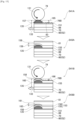
- Figs. 5 to 9 and Figs. 13 to 15 schematically illustrate each step of the shaping process. Further, the directions (the X-axis direction and the like) illustrated in Figs. 5 to 9 and Figs. 13 to 15 are examples.
- base member 70 is set on base table 60 of stage 52.
- the setting of base member 70 may be performed by a human, or may be automatically executed by shaping device 10.
- Controller 102 causes conveyance device 20 to move stage 52 on which base member 70 is set to a position below shaping unit 22.
- controller 102 moves stage 52 in the X-axis direction, and causes inkjet head 75 of printing section 72 to discharge ultraviolet curing resin 76 onto base member 70.
- Ink jet head 75 discharges ultraviolet curing resin 76 in a thin film form onto base member 70.
- Controller 102 may execute discharging using ink jet head 75 in S11, for example, by only one scan (one pass) along the X-axis direction, or may execute discharging by multiple scans.
- controller 102 rotates roller 79 of flattening device 78 on the upper surface of ultraviolet curing resin 76 in the thin film form to perform the flattening.
- controller 102 moves base member 70 (stage 52) in movement direction 133 opposite to rotation direction 131 of roller 79, and flattens ultraviolet curing resin 76 discharged in the first discharging process by roller 79.
- controller 102 rotates roller 79 about a rotation axis parallel to the Y-axis direction in counterclockwise rotation direction 131 in Fig. 6 .
- controller 102 moves stage 52 in movement direction 133 (direction toward the back in Fig.
- Controller 102 causes lifting and lowering device 64 to lift stage 52 to a position where roller 79 comes into contact with ultraviolet curing resin 76 discharged onto base member 70, thereby performing the flattening. Controller 102 makes the rotation speed of roller 79 in rotation direction 131 larger (faster) than the movement speed of stage 52 in movement direction 133.
- Roller 79 is brought into contact with ultraviolet curing resin 76 in a flowable state, transfers ultraviolet curing resin 76 to roller 79, scrapes up ultraviolet curing resin 76, and flattens the surface of ultraviolet curing resin 76 while collecting ultraviolet curing resin 76 by collection section 80.
- Operation directions and the like of base member 70 and roller 79 described above are examples.
- roller 79 may be configured to be movable in the X-axis direction, and controller 102 may perform the flattening by rotating roller 79 in rotation direction 131 while moving roller 79 in movement direction 133 or the direction opposite to movement direction 133.
- controller 102 irradiates the flattened ultraviolet curing resin 76 with ultraviolet rays by irradiation device 81.
- irradiation device 81 cures ultraviolet curing resin 76 by irradiating ultraviolet curing resin 76 (refer to Fig. 6 ) spread in a thin film form with ultraviolet rays to form first flattening layer 86 having insulating property.
- first flattening layer 86 having flattened first flattening surface 86A on the surface is formed.
- controller 102 determines whether first flattening layer 86 having a predetermined thickness has been formed (S17). Controller 102 performs a negative determination in S17, for example, until a thickness having a set value of control program 107 or a value designated by an operation input from the outside is reached (S17: NO). Controller 102 can determine the thickness of formed first flattening layer 86 based on, for example, the size of the liquid droplet of ultraviolet curing resin 76 discharged from ink jet head 75, the number of times S11 to S15 being repeatedly executed, and the like. Controller 102 stacks the insulating layers by repeatedly performing the processes of S11 to S15, and forms first flattening layer 86 having first flattening surface 86A on the surface and a predetermined thickness. Controller 102 does not have to execute the first flattening process in S13 each time S11 is executed. For example, controller 102 may execute the first flattening process in S13 each time S11 and S15 are executed multiple times.
- controller 102 determines in S17 that first flattening layer 86 having a predetermined thickness has been formed (S17: YES), in a second discharging process in S19, in order to smooth first flattening surface 86A of first flattening layer 86, controller 102 discharges ultraviolet curing resin 76 onto first flattening surface 86A.
- controller 102 discharges ultraviolet curing resin 76 onto first flattening surface 86A.
- flattened first flattening surface 86A can be formed on the surface of first flattening layer 86.
- Fig. 8 schematically illustrates first flattening layer 86 whose surface is flattened. As illustrated in Fig.
- fine unevenness 91 is formed on first flattening surface 86A of flattened first flattening layer 86 due to, for example, a difference in an amount of ultraviolet curing resin 76 discharged from the nozzles of ink jet head 75, a size of liquid droplets of ultraviolet curing resin 76, or the like.
- a height of unevenness 91 may be, for example, ⁇ 10 ⁇ m, and is extremely small compared with a size of roller 79. Therefore, even when first flattening surface 86A of first flattening layer 86 is flattened by roller 79, it is difficult to flatten first flattening surface 86A to the extent of fine unevenness 91.
- the surface on which fine unevenness 91 is formed is defined as a flattening surface.
- a surface on which fine unevenness 91 is reduced, or the unevenness of the surface is equal to or less than ⁇ 1 ⁇ m (it can be assumed that original unevenness 91 is eliminated) is defined as a smooth surface that is smoothed.
- first flattening surface 86A When unevenness 91 is formed on first flattening surface 86A, in a case where a metal wire is formed on first flattening surface 86A, a thickness of the metal wire to be formed varies. Alternatively, there is concern that the conductivity of the metal wire may be reduced by not completely baking the metal wire in a portion having a large thickness (metal fine particles do not contact or fuse). As a result, a resistance value of the metal wire becomes uniform, and thus it is difficult to obtain a desired high frequency characteristic.
- controller 102 performs smoothing to reduce or eliminate unevenness 91 by discharging ultraviolet curing resin 76 again to first flattening surface 86A of flattened first flattening layer 86.
- controller 102 discharges ultraviolet curing resin 76 to first flattening surface 86A by ink jet head 75.
- ultraviolet curing resin 76 in S11 is differentiated from ultraviolet curing resin 76 in the second discharging process in S19
- ultraviolet curing resin 76 in S19 will be referred to as second ultraviolet curing resin 76A.
- Controller 102 sets a discharging amount of second ultraviolet curing resin 76A in S19 to an amount corresponding to the size of unevenness 91. For example, when the height of formed unevenness 91 is large (a groove is deep), controller 102 executes a process for increasing a discharging amount of ink jet head 75. Controller 102 may discharge second ultraviolet curing resin 76A in a constant discharging amount regardless of the size of unevenness 91.
- controller 102 performs a semi-curing process on second ultraviolet curing resin 76A discharged in S19 (S23). Controller 102 semi-cures second ultraviolet curing resin 76A by irradiating second ultraviolet curing resin 76A with ultraviolet rays from irradiation device 81 (refer to Fig. 7 ).
- the semi-cured state referred to herein is a state in which the viscosity is reduced and the fluidity is improved, and is not completely stable at the physical property level.
- the semi-cured state is, for example, a state in which, when new second ultraviolet curing resin 76A is discharged onto the layer of semi-cured second ultraviolet curing resin 76A, discharged second ultraviolet curing resin 76A is not mixed with the layer and is cured to the extent of being placed (stacked) on the layer in the semi-cured state.
- controller 102 semi-cures second ultraviolet curing resin 76A by reducing the intensity of the ultraviolet ray (the intensity of the light) with which second ultraviolet curing resin 76A is irradiated, the scanning speed at which the ultraviolet ray is scanned, the number of scans, the irradiation time, the number of irradiations, and the like as compared with the normal curing process (the first curing process in S15 or the like).
- Controller 102 repeatedly executes the processes of S19 to S23 until the semi-cured layer having the predetermined thickness is formed (S25: NO), and stacks second ultraviolet curing resin 76A in the semi-cured state, as in S 17 described above.
- semi-cured layer 92 is formed on first flattening layer 86 by stacking semi-cured second ultraviolet curing resin 76A.
- Semi-cured second ultraviolet curing resin 76A spreads over fine unevenness 91 of first flattening surface 86A and is smoothed by a leveling effect, and forms smooth surface 93.
- the leveling effect as described herein is a phenomenon in which a surface area of a liquid is as small as possible by the surface tension.
- Second ultraviolet curing resin 76A changes in thickness to be flattened (more uniform) over time. Second ultraviolet curing resin 76A is applied and spread by being discharged onto first flattening surface 86A to fill unevenness 91.
- Fig. 10 is a schematic diagram illustrating raised portion 135. As illustrated in Fig. 10 , for example, in a case where shaped object 139 having a small width in which width 137 in the X-axis direction is several mm or less is shaped, raised portion 135 bulging upward in the Z-axis direction due to the surface tension of second ultraviolet curing resin 76A is formed in semi-cured layer 92.
- predetermined height 143 is, for example, a target height defined by three-dimensional data of control program 107 or the like, and is a height forming smooth surface 93.
- controller 102 executes the second flattening process of S27 to reduce the size of raised portion 135 (suppress the increase). Controller 102 moves stage 52 to the position of flattening device 78, and adjusts the height of stage 52 so that a lower end of roller 79 is disposed at the position of smooth surface 93, that is, predetermined height 143 as illustrated in Fig. 10 . As described above, in the present embodiment, the position of roller 79 in the X-axis direction or the Y-axis direction is fixed.
- the flattening by roller 79 is executed by adjusting the position at which roller 79 rotating in a state where this position is fixed comes into contact with semi-cured layer 92 to the position of the upper surface (smooth surface 93) of semi-cured layer 92 in the design data.
- the second flattening process may be performed while moving roller 79 without fixing the position of roller 79.
- Roller 79 may be positioned slightly above or below smooth surface 93.
- the method of aligning the position of roller 79 with the position of the upper surface of semi-cured layer 92 is not particularly limited.
- the position of the lower end of roller 79 may be adjusted to the target height for shaping smooth surface 93 based on the three-dimensional data of control program 107.
- the shaped object may be experimentally shaped, the height of the upper surface of semi-cured layer 92 may be measured, and the position of roller 79 may be adjusted.
- the position of roller 79 may be adjusted by measuring the height of the upper surface of semi-cured layer 92 shaped by a sensor or the like before executing S27 in the actual shaping process.
- stage 52 may be fixed, the position of roller 79 in the Z-axis direction may be adjusted, and the position of roller 79 may be aligned with the position of the upper surface of semi-cured layer 92. Both stage 52 and roller 79 may be moved in the Z-axis direction for adjustment.
- controller 102 moves stage 52 in movement direction 145 which is the same direction as rotation direction 131 of roller 79, and flattens semi-cured layer 92 by roller 79.
- the same direction as rotation direction 131 is, for example, a tangential direction of roller 79 parallel to the upper surface of stage 52 and the same direction as rotation direction 131. Since the position of roller 79 is fixed as described above, roller 79 rotates in a state where the position in movement direction 145 of stage 52, for example, the X-axis direction is fixed.
- Fig. 11 is a schematic diagram of the first flattening process.
- the flattening is executed after one first discharging process (S11). For this reason, one liquid droplet is smaller in ultraviolet curing resin 76 which is a target of the first flattening process than in a state in which second ultraviolet curing resin 76A in the semi-cured state is stacked in many layers as in the second flattening process.
- ultraviolet curing resin 76 an intermolecular force between the liquid droplets themselves and between the liquid droplet and the cured film (the already cured portion of first flattening layer 86) is weak (refer to the arrow in Fig. 11 ).
- rotation direction 131 and movement direction 133 are set to opposite directions, and a force is applied from roller 79 to ultraviolet curing resin 76 in the direction of arrow 147 illustrated in Fig. 11 , so that the excess amount of ultraviolet curing resin 76 is transferred to roller 79 and can be quickly and efficiently flattened. As a result, a shaping time can be shortened.
- Fig. 12 is a schematic diagram of the second flattening process.
- the cycle of S19 to S23 is executed multiple times in order to fill unevenness 91, and second ultraviolet curing resin 76A in the semi-cured state is stacked.
- the liquid film formed by the liquid droplets of second ultraviolet curing resin 76A is large, and the intermolecular force between the liquid droplets themselves or the liquid droplets and first flattening layer 86 is strong (refer to an arrow in Fig. 12 ).
- controller 102 makes the rotation speed of roller 79 in rotation direction 131 larger (faster) than the movement speed of stage 52 in movement direction 133.
- controller 102 sets the rotation speed of roller 79 to several times the movement speed of stage 52. Accordingly, in the first flattening process in which the intermolecular force is weaker than that in the second flattening process and the liquid droplets are easily transferred, roller 79 is rotated at a high speed, the transfer amount to roller 79 per other unit time is increased, and the time required for the first flattening process can be shortened. As a result, the shaping time can be shortened.
- controller 102 sets the movement speed of stage 52 in movement direction 145 to be equal to the rotation speed of roller 79 in rotation direction 131. Accordingly, the difference in the relative movement speed between roller 79 and second ultraviolet curing resin 76A on stage 52 is eliminated, and roller 79 can be brought into a state as if roller 79 suppresses second ultraviolet curing resin 76A from above.
- the second flattening process in which the intermolecular force is strong and the transfer of the liquid droplets is difficult compared to the first flattening process, it is possible to more reliably transfer excess second ultraviolet curing resin 76A to roller 79 by eliminating the relative movement of roller 79 and second ultraviolet curing resin 76A.
- controller 102 executes a second curing process of curing semi-cured layer 92 (S29). Controller 102 moves stage 52 to irradiation device 81, and irradiates semi-cured layer 92 on which the second flattening process has been performed with ultraviolet rays. Second ultraviolet curing resin 76A is irradiated with ultraviolet rays to increase the viscosity, and thus, second ultraviolet curing resin 76A is cured to fill unevenness 91. Smooth layer 151 obtained by curing semi-cured layer 92 is formed on first flattening layer 86 (refer to Fig. 13 ).
- Smooth surface 93 formed on the upper surface of smooth layer 151 is a surface in which unevenness 91 is reduced or eliminated by the leveling effect described above. Further, smooth surface 93 becomes a surface in which raised portion 135 is smaller or eliminated than that in the second flattening process.
- controller 102 forms a metal wire at a predetermined position on smooth surface 93 based on three-dimensional data of control program 107. Specifically, in the metal fluid discharging process of S31 of Fig. 4 , controller 102 causes inkjet head 75 to discharge metal ink 77 in a thin film shape onto smooth surface 93 of smooth layer 151 (refer to Fig. 13 ). In a conductor forming process in S33, controller 102 causes heater 82 to heat and bake metal ink 77 discharged onto smooth surface 93 (refer to Fig. 14 ). In S35, controller 102 determines whether metal wire 95 having a desired thickness or shape has been formed.
- controller 102 performs a negative determination in S35 up to the number of times set in advance (S35: NO), and repeatedly executes S31 and S33 to form desired metal wire 95 on smooth surface 93.
- Desired metal wire 95 described herein is metal wire 95 that satisfies a required thickness, shape, position, or electrical characteristics.
- controller 102 performs an affirmative determination in S35 (S35: YES), and executes S38. Consequently, it is possible to shape first flattening layer 86 (wiring board) in which metal wire 95 is formed on smooth surface 93.
- metal ink 77 is discharged and cured on first flattening surface 86A on which unevenness 91 is formed to form metal wire 95
- a thickness of metal wire 95 is made nonuniform due to unevenness 91.
- failures such as an increase in a resistance value of metal wire 95, disconnection, and deterioration of high frequency characteristic may occur.
- metal wire 95 having a more uniform thickness can be formed by reducing fine unevenness 91 of first flattening surface 86A or raised portion 135, discharging metal ink 77 onto reduced smooth surface 93, and the like.
- the resistance value of metal wire 95 can be reduced to a desired value, and thus the occurrence of disconnection can be suppressed.
- controller 102 determines whether to form two or more smooth layers 151 and to form uppermost second flattening layer 153A (refer to Fig. 16 ) to be described later (S38). At this time, since only one smooth layer 151 is formed, controller 102 makes a negative determination (S38: NO) and executes S39. A case where multiple smooth layers 151 are formed and details of uppermost second flattening layer 153A will be described later.
- a third discharging process (S39) and a third flattening process (S41) are executed.
- the shape of raised portion 135 may remain in the shaping of the upper layer. This is because, as described above, the force with which the ultraviolet curing resin discharged to raised portion 135 adheres to raised portion 135 (base) due to the surface tension is stronger than the ultraviolet curing resin printed on the flat surface such as smooth surface 93.
- controller 102 discharges ultraviolet curing resin 76 onto smooth layer 151, and executes the third flattening process according to the height of raised portion 135. More specifically, in S39, the controller causes inkjet head 75 to discharge ultraviolet curing resin 76 onto smooth surface 93.
- ultraviolet curing resin 76 in S11 is differentiated from ultraviolet curing resin 76 in the third discharging process in S39
- ultraviolet curing resin 76 in S39 will be referred to as third ultraviolet curing resin 76B.
- the order and the contents of the processes illustrated in Figs. 3 and 4 are examples, and for example, in a case where the shaping of metal wire 95 is further performed at another position of smooth surface 93 after executing S35, the processes of S31 to S35 may be repeatedly performed.
- controller 102 flattens discharged third ultraviolet curing resin 76B with roller 79.
- controller 102 causes irradiation device 81 to irradiate flattened third ultraviolet curing resin 76B with ultraviolet rays to form a thin insulating layer (S43).
- controller 102 determines whether second flattening layer 153 having a predetermined thickness set by control program 107 or the like has been formed (S45).
- Controller 102 repeatedly executes S39, S41, and S43 until second flattening layer 153 having a predetermined thickness can be formed (S45: NO) to stack the insulating layers, thereby forming second flattening layer 153 having a predetermined thickness. Controller 102 does not have to execute the third flattening process in S41 each time S39 is executed.
- Fig. 15 illustrates a state where first layer 155 and second layer 156 included in second flattening layer 153 are formed. In Fig. 15 , metal wire 95 is not illustrated.
- First layer 155 is the lowermost layer among the multiple insulating layers included in second flattening layer 153.
- Second layer 156 is an insulating layer one layer above first layer 155. That is, first layer 155 is an insulating layer formed in the first cycle of S39, S41, and S43, and second layer 156 is an insulating layer formed in the second cycle.
- controller 102 provides roller 79 at a height corresponding to the height of raised portion 135 formed in smooth layer 151, and increases the number of scans of the flattening by roller 79 to be larger than that in the first flattening process in S13.
- Raised portion 135 formed in smooth layer 151 here is raised portion 135 formed (remaining) even after the second flattening process of S27 is performed.
- Controller 102 uses, as the height corresponding to the height of raised portion 135, height 157 (refer to the uppermost diagram of Fig. 15 ) at which roller 79 is not in contact with raised portion 135 formed in smooth layer 151 and roller 79 is in contact with third ultraviolet curing resin 76B discharged onto raised portion 135 in the third discharging process of S39.
- S41A and S43A in Fig. 15 respectively indicate a first instance of the third flattening process and a first instance of the third curing process
- S41B and S43B respectively indicate a second instance of the third flattening process and a second instance of the third curing process.
- controller 102 adjusts the height of stage 52 and provides roller 79 at a position where roller 79 is not in contact with raised portion 135 of smooth layer 151 and is in contact with third ultraviolet curing resin 76B discharged in a first instance of the third discharging process, that is, discharged onto raised portion 135. Accordingly, it is possible to avoid interference between roller 79 and raised portion 135 and to suppress occurrence of breakage or the like of the shaped object.
- third ultraviolet curing resin 76B discharged onto raised portion 135 is collected by roller 79 or stacked on smooth surface 93 recessed from raised portion 135. As a result, it is possible to stack a larger amount of third ultraviolet curing resin 76B on smooth surface 93 than raised portion 135.
- controller 102 executes the third curing process of S43A. Accordingly, for cured first layer 155, assuming that third ultraviolet curing resin 76B is temporarily stacked on raised portion 135, protruding portion 158 that is more elevated than the remaining portions is formed on raised portion 135.
- first layer 155 is flattened at the height of the apex of raised portion 135. That is, first layer 155 preferably has a flat surface on which protruding portion 158 is not formed.
- controller 102 adjusts the height of stage 52 and provides roller 79 at a height corresponding to the height of raised portion 135 in the third flattening process (S41B). Controller 102 provides roller 79 at height 160 at which roller 79 does not come into contact with protruding portion 158 stacked on raised portion 135 and roller 79 comes into contact with third ultraviolet curing resin 76B discharged onto protruding portion 158 to perform the flattening.
- second layer 156 cured in S43B preferably has a flat surface formed as an upper surface.
- height difference 163 between the apex of elevated protruding portion 161 stacked on protruding portion 158 and the remaining portions of second layer 156 is further reduced. That is, the elevation can be further reduced.
- Controller 102 may adjust the height of stage 52 based on a set value set in advance in control program 107.
- the height of stage 52 (roller 79) may be determined by experimentally shaping the shaped object and measuring the heights of raised portion 135 and protruding portions 158 and 161. Alternatively, before performing S41 in the actual shaping process, the height of roller 79 may be adjusted by measuring the height of raised portion 135 or protruding portion 158 shaped by a sensor or the like.
- the position of stage 52 may be fixed, and the position of roller 79 in the Z-axis direction may be adjusted to adjust the position of roller 79, or both stage 52 and roller 79 may be moved in the Z-axis direction to adjust the position.
- controller 102 executes the flattening by setting the distance between smooth surface 93 (upper surface) of smooth layer 151 and roller 79 in the Z-axis direction as first distance 165.
- controller 102 executes the flattening by setting the distance between the upper surface of first layer 155 and roller 79 in the Z-axis direction as second distance 166. Controller 102 makes second distance 166 shorter than first distance 165.
- the difference between second distance 166 and first distance 165 is preferably a difference between the distance between the apex of raised portion 135 and smooth surface 93 and the distance between the upper surface of first layer 155 and the apex of protruding portion 158.
- roller 79 it is possible to bring roller 79 closer to the flat surface (upper surface) by the distance by which the elevation of raised portion 135 can be suppressed by the shaping of first layer 155.
- second distance 166 By setting second distance 166 to be shorter than first distance 165, roller 79 can be brought closer to protruding portion 158 to effectively perform flattening.
- controller 102 may gradually shorten the distance between the upper surface of the insulating layer cured in the previous cycle and roller 79 as the cycle proceeds, that is, toward the upper layers. That is, when first layer 155, second layer 156, the third layer (not illustrated), ... are stacked, the distance between the upper surface of each layer and roller 79 may be gradually shortened. Accordingly, roller 79 is relatively brought close to the upper surface of the shaped object as height differences 159 and 163 become smaller, and protruding portions 158 and 161 can be more flattened.
- controller 102 increases the number of scans of roller 79 in the third flattening process to be larger than that in the first flattening process of S13.
- the surface on which raised portion 135 is not formed is flattened by discharging ultraviolet curing resin 76.
- liquid droplets of ultraviolet curing resin 76 are present on a flat base, and for example, excess liquid droplets can be transferred to roller 79 by being scraped by a squeegee. Therefore, it is easy to transfer ultraviolet curing resin 76 to roller 79.
- the third flattening process as illustrated in S41A and S41B of Fig. 15 , for example, there is a liquid droplet of third ultraviolet curing resin 76B on raised portion 135 or protruding portion 158 of the curved surface shape, and the liquid droplet cannot be collected by roller 79 as if a flat surface is scraped by a squeegee. Further, due to the curved surface shape, the contact time between the liquid droplet on raised portion 135 or protruding portion 158 and roller 79 is short, and there is a concern that the transfer may become difficult by one scan. Then, controller 102 increases the number of scans of the third flattening process.
- controller 102 multiplies the number of scans in S41 by several times as compared with the number of scans in S13.
- controller 102 multiplies the number of scans in S41 by several times as compared with the number of scans in S13.
- controller 102 moves stage 52 in the direction opposite to rotation direction 131 of roller 79 to perform the flattening (refer to Fig. 15 ). Accordingly, similarly to the first flattening process, a force is applied from roller 79 to ultraviolet curing resin 76 in the direction of arrow 147 illustrated in Fig. 11 , and the excess amount of ultraviolet curing resin 76 is transferred to roller 79 and can be quickly and efficiently flattened.
- controller 102 increases the rotation speed of the roller compared to the movement speed of stage 52.
- controller 102 sets the rotation speed of roller 79 to several times the movement speed of stage 52. Accordingly, in the third flattening process in which the intermolecular force is weaker than that in the second flattening process and the liquid droplets are easily transferred, roller 79 is rotated at a high speed, the transfer amount to roller 79 per other unit time is increased, and the time required for the third flattening process can be shortened. As a result, the shaping time can be shortened.
- controller 102 determines whether to further stack smooth layer 151 or whether multiple smooth layers 151 are already stacked (S47).
- smooth layer 151 or metal wire 95 is further formed on second flattening layer 153, or when two or more smooth layers 151 are already formed (S47: YES)
- controller 102 executes S19, and executes shaping of smooth layer 151, shaping of metal wire 95, and the like.
- controller 102 forms first flattening layer 86 on second flattening layer 153 (S51) and ends the shaping.
- controller 102 determines whether to form uppermost second flattening layer 153A (refer to Fig. 16 ), which is another condition, in S38 since two or more smooth layers 151 are formed and the first condition of S38 is satisfied.
- Uppermost second flattening layer 153A is a layer formed as the uppermost second flattening layer 153 when multiple combinations of smooth layer 151 and second flattening layer 153 are stacked.
- controller 102 does not form uppermost second flattening layer 153A, that is, when the formation of second flattening layer 153 and smooth layer 151 is continued (S38: NO)
- controller 102 executes S39 and the subsequent steps. Accordingly, it is possible to perform the flattening by performing S39 to S45 on raised portion 135 formed by the second and subsequent shaping of smooth layer 151.
- Controller 102 repeatedly executes S19 to S35 and S39 to S45 to repeatedly form and stack smooth layer 151 and second flattening layer 153.
- Fig. 16 illustrates shaped object 171 in which four layers of second flattening layer 153 (including uppermost second flattening layer 153A) and smooth layer 151 are stacked as an example of the completed shaped object. In Fig. 16 , metal wire 95 is not illustrated.
- controller 102 shapes shaped object 171 in which smooth layer 151 and second flattening layer 153 are alternately formed and stacked.
- controller 102 After smooth layer 151 and second flattening layer 153 are alternately formed and stacked, when controller 102 reaches the stage of forming uppermost second flattening layer 153A, controller 102 makes an affirmative determination in S38 (S38: YES) and forms uppermost second flattening layer 153A (S49). In the processes of S19 to S29 before performing S49, uppermost smooth layer 151A of the uppermost layer illustrated in Fig. 16 is formed. In S49, controller 102 forms the flattening layer by repeatedly executing the same process as the formation of second flattening layer 153 (the same process as S39, S41, and S43).
- controller 102 increases the number of times of repeating S39, S41, and S43 to be larger than the number of times of repeating S39, S41, and S43 when forming other second flattening layers 153 (first-stage second flattening layer 153, second-stage second flattening layer 153, and the like illustrated in Fig. 16 ) which are layers below uppermost second flattening layer 153A.
- second flattening layers 153 first-stage second flattening layer 153, second-stage second flattening layer 153, and the like illustrated in Fig. 16
- uppermost second flattening layer 153A as the uppermost layer is formed to be thick, and the number of times of flattening accumulated raised portion 135 is increased, so that the accumulated unevenness can be flattened collectively.
- the condition for forming uppermost second flattening layer 153A is not limited to the condition for forming two or more smooth layers 151, and may be a condition for forming a predetermined number or more of smooth layers 151. Controller 102 may execute the mounting of the electronic components by mounting unit 23 after the shaped object is shaped.
- controller 102 may discharge metal ink 77 from ink jet head 75 onto metal wire 95, and may cause mounting unit 23 to provide the electronic components such that the discharged ink and the terminals of the electronic components are in contact with each other. Controller 102 may connect the electronic component to metal wire 95 (circuit) by baking metal ink 77 with heater 82.
- Controller 102 of shaping device 10 executes a first discharging process (S11) of discharging ultraviolet curing resin 76 from above stage 52, a first flattening process (S13) of flattening ultraviolet curing resin 76 discharged in S11 by roller 79, and a first curing process (S15) of curing ultraviolet curing resin 76 flattened in S13. Controller 102 repeatedly executes S11, S13, and S15 until the thickness reaches the predetermined thickness (S17: NO) to form first flattening layer 86.
- controller 102 executes a second discharging process (S19) of discharging second ultraviolet curing resin 76A from above stage 52 and a semi-curing process (S23) of semi-curing second ultraviolet curing resin 76A discharged in S19. Controller 102 repeatedly executes S19 and S23 until a predetermined thickness is reached (S25: NO) to form semi-cured layer 92 on stage 52.
- controller 102 executes a second flattening process (S27) of flattening semi-cured layer 92 by roller 79, a second curing process (S29) of curing semi-cured layer 92 flattened in S27 to form smooth layer 151, and a third discharging process (S39) of discharging third ultraviolet curing resin 76B onto smooth layer 151 cured in S29.
- controller 102 provides roller 79 at a height corresponding to height 157 of raised portion 135 formed in smooth layer 151, and increases the number of scans of flattening by roller 79 more than in S13.
- Controller 102 cures third ultraviolet curing resin 76B flattened in S41 (S43). Controller 102 repeatedly executes S39, S41, and S43 until the thickness reaches the predetermined thickness (S45: NO) to form second flattening layer 153 on smooth layer 151.
- roller 79 when flattening third ultraviolet curing resin 76B discharged onto smooth layer 151, roller 79 is disposed at a height corresponding to the height of raised portion 135 of smooth layer 151 to perform the flattening. While avoiding interference between raised portion 135 and roller 79, it is possible to bring roller 79 into contact with third ultraviolet curing resin 76B discharged onto raised portion 135 and perform the flattening. In addition, by increasing the number of scans for flattening, it is possible to increase the total time during which roller 79 comes into contact with third ultraviolet curing resin 76B discharged onto raised portion 135, and it is possible to suppress an increase in raised portion 135 by transferring and removing excessive third ultraviolet curing resin 76B onto roller 79. As a result, the influence of raised portion 135 on the upper layer can be reduced.
- controller 102 of control device 26 includes first discharging section 110, first flattening section 111, first curing section 112, first flattening layer forming section 113, second discharging section 115, semi-curing section 116, semi-cured layer forming section 117, second flattening section 118, second curing section 119, third discharging section 120, third flattening section 121, third curing section 122, and second flattening layer forming section 123.
- First discharging section 110 and the like are, for example, processing modules achieved by executing control program 107 in the CPU of controller 102.
- First discharging section 110 and the like may be configured with hardware instead of software.
- First discharging section 110 is a functional unit that discharges ultraviolet curing resin 76 from inkjet head 75 above stage 52.
- First flattening section 111 is a functional unit that flattens ultraviolet curing resin 76 discharged from first discharging section 110 by roller 79.
- First curing section 112 is a functional unit that cures ultraviolet curing resin 76 flattened by first flattening section 111 by curing section 74.
- First flattening layer forming section 113 is a functional unit that repeatedly executes S 11, S13, and S 15 to form first flattening layer 86 on stage 52.
- Second discharging section 115 is a functional unit that causes ink jet head 75 to discharge second ultraviolet curing resin 76A onto stage 52.
- Semi-curing section 116 is a functional unit that causes curing section 74 to further semi-cure second ultraviolet curing resin 76A discharged by second discharging section 115.
- Semi-cured layer forming section 117 is a functional unit that repeatedly executes S19 and S23 to form semi-cured layer 92 on stage 52.
- Second flattening section 118 is a functional unit that flattens semi-cured layer 92 by roller 79.
- Second curing section 119 is a functional unit that cures semi-cured layer 92 flattened by second flattening section 118 to form smooth layer 151.
- Third discharging section 120 is a functional unit that discharges third ultraviolet curing resin 76B onto smooth layer 151 cured by second curing section 119.
- Third flattening section 121 is a functional unit that provides roller 79 at height 157 corresponding to the height of raised portion 135 formed in smooth layer 151, increases the number of scans of the flattening by roller 79 to be larger than that in the first flattening process, and flattens third ultraviolet curing resin 76B discharged by third discharging section 120 by roller 79.
- Third curing section 122 is a functional unit that cures third ultraviolet curing resin 76B flattened by third flattening section 121.
- Second flattening layer forming section 123 is a functional unit that repeatedly executes S39, S41, and S43 to form second flattening layer 153 on smooth layer 151.
- curing section 74 is an example of a curing device.
- Ink jet head 75 is an example of a discharging device.
- Ultraviolet curing resin 76 and third ultraviolet curing resin 76B are examples of first curable viscous fluid.
- Metal ink 77 is an example of fluid containing metal particles.
- Second ultraviolet curing resin 76A is an example of second curable viscous fluid.
- Roller 79 is an example of a flattening member.
- Metal wire 95 is an example of a conductor.
- S11 is an example of a first discharging step and a first flattening layer forming step.
- S13 is an example of first flattening step and a first flattening layer forming step.
- S15 is an example of a first curing step and a first flattening layer forming step.
- S19 is an example of a second discharging step and a semi-cured layer forming step.
- S23 is an example of a semi-curing step and a semi-cured layer forming step.
- S27 is an example of a second flattening step.
- S29 is an example of a second curing step.
- S31 is an example of a metal fluid discharging step.
- S33 is an example of a conductor forming step.
- S39 is an example of a third discharging step and a second flattening layer forming step.
- S41 is an example of a third flattening step and a second flattening layer forming step.
- S43 is an example of a third curing step and a second flattening layer forming step.
- first flattening layer 86 is shaped on base member 70 of stage 52, and smooth layer 151 is shaped on first flattening layer 86; however, the configuration is not limited to this.
- semi-cured layer 92 may be shaped on base member 70, first flattening layer 86 may be shaped on smooth layer 151, and smooth layer 151 may be further shaped on first flattening layer 86.
- controller 102 may place the height of roller 79 at a position where roller 79 contacts raised portion 135. Accordingly, the height corresponding to the height of raised portion 135 of the present disclosure can be appropriately changed according to the size, shape, and the like of raised portion 135.
- Controller 102 shortens the distance between the upper surface of second layer 156 and roller 79 as compared to first layer 155, but may make the distance equal thereto or longer.
- Controller 102 needs not increase the number of cycles of S39, S41, and S43 in the shaping of uppermost second flattening layer 153A.
- Controller 102 needs not move stage 52 in the direction opposite to rotation direction 131 of roller 79 in at least one of S13 and S41.
- controller 102 may execute the flattening by setting the movement direction of stage 52 to the same direction as rotation direction 131.
- controller 102 may move stage 52 in a direction opposite to rotation direction 131.
- controller 102 may set the rotation speed of roller 79 to be equal to or lower than the movement speed of stage 52.
- controller 102 may make the movement speed of stage 52 higher or lower than the rotation speed of roller 79.
- Controller 102 needs not form metal wire 95.
- shaping device 10 the position of roller 79 is fixed, but the position needs not be fixed.
- shaping device 10 may move roller 79 in each of the X, Y, and Z axial directions to perform the flattening.
- Controller 102 needs not mount the electronic components.
- the first curable viscous fluid and the second curable viscous fluid of the present disclosure are not limited to ultraviolet curing resin 76, and various curable viscous fluid that are cured by light, heat, or the like may be employed. Therefore, a method of curing the first curable viscous fluid and the second curable viscous fluid is not limited to the ultraviolet ray.
- the first curable viscous fluid and the second curable viscous fluid may be different types of curable viscous fluid.
- the fluid containing metal particles of the present disclosure is not limited to metal ink 77 containing silver, and may employ fluid containing another metal.
- shaping device 10 for manufacturing a wiring board is employed as a shaping device of the present disclosure, but the present disclosure is not limited to this.
- various manufacturing devices that perform shaping using the first curable viscous fluid and the second curable viscous fluid can be employed.
Landscapes
- Engineering & Computer Science (AREA)
- Chemical & Material Sciences (AREA)
- Materials Engineering (AREA)
- Manufacturing & Machinery (AREA)
- Mechanical Engineering (AREA)
- Physics & Mathematics (AREA)
- Optics & Photonics (AREA)
- Automation & Control Theory (AREA)
- Composite Materials (AREA)
- Microelectronics & Electronic Packaging (AREA)
- Application Of Or Painting With Fluid Materials (AREA)
Abstract
Description
- The present disclosure relates to a shaping method and a shaping device that perform shaping using curable viscous fluid.
- Conventionally, there has been developed a technique related to a shaping method for shaping a shaped object by using curable viscous fluid such as an ultraviolet curing resin. Specifically, in this shaping method, for example, curable viscous fluid is discharged by a discharging device, the discharged curable viscous fluid is cured by irradiation with ultraviolet rays, and a desired shaped object is shaped with a cured layer that has been cured. In the following Patent Literature 1, a first unit layer to which an ultraviolet curing resin has been discharged is semi-cured by irradiating the first unit layer with ultraviolet rays, and a flattening process of the first unit layer is performed by a flattening roller unit.
- Patent Literature 1:
JP-A-2018-114657 - In the above-described semi-curing step of the ultraviolet curing resin, a locally raised portion may be formed by a surface tension of the ultraviolet curing resin. For example, an end portion of the shaped object or a central portion of the shaped object having a small width of several mm or less becomes higher than a target height in the design data due to the surface tension. As a result, a shape of an upper layer and a shape of a shaped object of a finished product may be affected by the locally raised portion.
- The present disclosure has been made in view of such circumstances, and an object thereof is to provide a shaping method and a shaping device capable of reducing an influence of a raised portion of a semi-cured layer on an upper layer.
- In order to solve the above problem, according to an aspect of the present disclosure, there is provided a shaping method including: a first discharging step of discharging first curable viscous fluid from above a stage; a first flattening step of flattening the first curable viscous fluid discharged in the first discharging step by a flattening member; a first curing step of curing the first curable viscous fluid flattened in the first flattening step; a first flattening layer forming step of forming a first flattening layer on the stage by repeatedly executing the first discharging step, the first flattening step, and the first curing step; a second discharging step of discharging second curable viscous fluid from above the stage; a semi-curing step of semi-curing the second curable viscous fluid discharged in the second discharging step; a semi-cured layer forming step of forming a semi-cured layer on the stage by repeatedly executing the second discharging step and the semi-curing step; a second flattening step of flattening the semi-cured layer by the flattening member; a second curing step of curing the semi-cured layer flattened in the second flattening step to form a smooth layer; a third discharging step of discharging the first curable viscous fluid onto the smooth layer cured in the second curing step; a third flattening step of providing the flattening member at a height corresponding to a height of a raised portion formed on the smooth layer and flattening the first curable viscous fluid discharged in the third discharging step, by the flattening member, by increasing the number of scans of flattening by the flattening member to be larger than that in the first flattening step; a third curing step of curing the first curable viscous fluid flattened in the third flattening step; and a second flattening layer forming step of forming a second flattening layer on the smooth layer by repeatedly executing the third discharging step, the third flattening step, and the third curing step.
- The content of the present disclosure is not limited to being implemented as the shaping method, and it is extremely effective to be implemented as a shaping device including a discharging device, a roller, a curing device, and a control device.
- With the manufacturing method and the manufacturing device of the present disclosure, when the first curable viscous fluid discharged onto the smooth layer is flattened, the flattening member is disposed at the height corresponding to the height of the raised portion of the smooth layer to flatten the first curable viscous fluid. The flattening can be performed by bringing the flattening member into contact with the first curable viscous fluid discharged onto the raised portion while avoiding interference between the raised portion and the flattening member. In addition, by increasing the number of scans of the flattening, the total time during which the first curable viscous fluid discharged onto the raised portion and the flattening member are in contact with each other can be increased, and by removing the excess first curable viscous fluid, an increase in the raised portion can be suppressed. As a result, the influence of the raised portion of the smooth layer obtained by curing the semi-cured layer on an upper layer can be reduced.
-
-
Fig. 1 is a diagram illustrating a shaping device according to the present embodiment. -
Fig. 2 is a block diagram illustrating a control device. -
Fig. 3 is a flowchart illustrating a content of a shaping process. -
Fig. 4 is a flowchart illustrating the content of the shaping process. -
Fig. 5 is a schematic diagram illustrating a state in which an ultraviolet curing resin is being discharged from an inkjet head. -
Fig. 6 is a schematic diagram illustrating a state in which an ultraviolet curing resin is being flattened by a flattening device. -
Fig. 7 is a schematic diagram illustrating a state in which the flattened ultraviolet curing resin is being cured by a curing section to form a first flattening layer. -
Fig. 8 is a schematic diagram illustrating the first flattening layer whose surface is flattened. -
Fig. 9 is a schematic diagram illustrating a semi-cured layer whose surface is smoothed. -
Fig. 10 is a schematic diagram illustrating a raised portion. -
Fig. 11 is a schematic diagram of a first flattening process. -
Fig. 12 is a schematic diagram of a second flattening process. -
Fig. 13 is a schematic diagram illustrating a state in which metal ink is discharged. -
Fig. 14 is a schematic diagram illustrating a state in which a metal wire is being formed. -
Fig. 15 is a schematic diagram illustrating states of a third flattening process and a third curing process. -
Fig. 16 is a schematic diagram of a shaped object. - Hereinafter, a shaping method and a shaping device according to an embodiment of the present disclosure will be described.
Fig. 1 illustratesshaping device 10 according to the present embodiment. As illustrated inFig. 1 ,shaping device 10 includesconveyance device 20,shaping unit 22,mounting unit 23,inspection unit 24, and control device 26 (refer toFig. 2 ).Conveyance device 20,shaping unit 22,mounting unit 23, andinspection unit 24 are disposed onbase 28 ofshaping device 10.Base 28 generally has a rectangular shape. In the following description, a longitudinal direction ofbase 28 will be referred to as an X-axis direction, a transverse direction ofbase 28 will be referred to as a Y-axis direction, and a direction orthogonal to both the X-axis direction and the Y-axis direction will be referred to as a Z-axis direction. -
Conveyance device 20 includesX-axis slide mechanism 30 and Y-axis slide mechanism 32.X-axis slide mechanism 30 includesX-axis slide rail 34 andX-axis slider 36.X-axis slide rail 34 is disposed onbase 28 to extend in the X-axis direction.X-axis slider 36 is held byX-axis slide rail 34 to be slidable in the X-axis direction. Furthermore,X-axis slide mechanism 30 includes electromagnetic motor 38 (refer toFig. 2 ) and movesX-axis slider 36 to any position in the X-axis direction by drivingelectromagnetic motor 38. - In addition, Y-
axis slide mechanism 32 includes Y-axis slide rail 50 andstage 52. Y-axis slide rail 50 is disposed to extend in the Y-axis direction onbase 28. One end portion of Y-axis slide rail 50 in the Y-axis direction is coupled toX-axis slider 36. Consequently, Y-axis slide rail 50 is configured to be movable in the X-axis direction in accordance with sliding movement ofX-axis slider 36.Stage 52 is held to be slidable in the Y-axis direction by Y-axis slide rail 50. Y-axis slide mechanism 32 has electromagnetic motor 56 (refer toFig. 2 ), and movesstage 52 to any position in the Y-axis direction by drivingelectromagnetic motor 56. Consequently,stage 52 can be moved to any position in the X-axis direction and the Y-axis direction onbase 28 by drivingX-axis slide mechanism 30 and Y-axis slide mechanism 32. -
Stage 52 includes base table 60,holding device 62, and lifting andlowering device 64. Base table 60 is formed in a flat plate shape, and base member 70 (refer toFig. 5 ) is placed on an upper surface thereof.Base member 70 is, for example, a plate made of a metal such as iron or stainless steel.Holding devices 62 are provided on both side portions of base table 60 in the X-axis direction.Base member 70 is placed on base table 60 and is fixedly held with respect to base table 60 by sandwiching both edge portions in the X-axis direction byholding device 62. Lifting and loweringdevice 64 is disposed below base table 60 to lift and lower base table 60 in the Z-axis direction. -
Shaping unit 22 is a unit that shapes a structure onbase member 70 placed on base table 60 ofstage 52, and includesprinting section 72 andcuring section 74. As illustrated inFig. 5 , printingsection 72 hasink jet head 75, and discharges fluid in a thin film form onbase member 70 placed on base table 60. As the fluid discharged byinkjet head 75, ultraviolet curing resin 76 (refer toFig. 5 ) that is cured by ultraviolet rays may be employed.Ultraviolet curing resin 76 is an example of first and second curable viscous fluid of present disclosure. As the curable viscous fluid, other viscous fluid such as a thermosetting resin may be employed in addition to an ultraviolet curing resin. -
Inkjet head 75 is capable of discharging, for example,metal ink 77 in addition to ultraviolet curing resin 76 (refer toFig. 13 ).Metal ink 77 is an example of fluid containing metal particles of the present disclosure.Metal ink 77 is, for example, one in which fine particles of a metal (such as silver) having a nanometer size are dispersed in a solvent, and is cured by baking with heat. The surface of the metal fine particle is coated with, for example, a dispersant to suppress aggregation in the solvent. - When
inkjet head 75 dischargesultraviolet curing resin 76,ultraviolet curing resin 76 is discharged from multiple nozzles by, for example, a piezo method using a piezoelectric element. Note thatinkjet head 75 may dischargeultraviolet curing resin 76 from multiple nozzles by a thermal method of heatingultraviolet curing resin 76 to generate bubbles and performing discharging from the nozzles. In a case of dischargingmetal ink 77,inkjet head 75 dischargesmetal ink 77 from multiple nozzles, for example, according to a piezo method using piezoelectric elements. A discharging device is not limited toink jet head 75 including multiple nozzles, and may be, for example, a dispenser including a single nozzle.Inkjet head 75 may separately include a nozzle dischargingmetal ink 77 and a nozzle dischargingultraviolet curing resin 76, or may share a nozzle discharging two viscous fluid. In the following description,ultraviolet curing resin 76 andmetal ink 77 may be collectively referred to as viscous fluid. - As illustrated in
Fig. 2 , curingsection 74 includes flatteningdevice 78,irradiation device 81, andheater 82. Flatteningdevice 78 is a device which flattens an upper surface ofultraviolet curing resin 76 ormetal ink 77 discharged ontobase member 70 byink jet head 75. Flatteningdevice 78 includesroller 79 and collection section 80 (refer toFig. 6 ).Roller 79 has, for example, a cylindrically columnar shape, and rotates in contact with the viscous fluid (ultraviolet curing resin 76 or metal ink 77) in a flowable state based on the control of flatteningdevice 78, and flattens the viscous fluid while transferring the excess viscous fluid.Collection section 80 has, for example, a blade protruding toward the surface ofroller 79, scrapes the viscous fluid transferred toroller 79 by the blade, stores the viscous fluid scraped by the blade, and discharges the viscous fluid.Collection section 80 discharges, for example, the collected viscous fluid to a waste liquid tank. Flatteningdevice 78 flattens the surface of the viscous fluid by scraping the excess viscous fluid while leveling the surface of the viscous fluid. - Flattening
device 78 is not limited to a configuration in which the flattening is performed byroller 79. For example, flatteningdevice 78 may have a configuration in which a plate-shaped member such as a squeegee comes into contact with the surface of the viscous fluid to perform the flattening. Alternatively, flatteningdevice 78 may have a configuration for leveling the surface of the viscous fluid by using a brush or a rake.Collection section 80 may return the collected viscous fluid to a supply tank again. The flattening by flatteningdevice 78 needs not be performed every time the viscous fluid is discharged. For example, the flattening may be performed only when a specific layer is formed. -
Irradiation device 81 irradiates, for example,ultraviolet curing resin 76 discharged ontobase member 70 with ultraviolet rays.Ultraviolet curing resin 76 is cured by irradiation with ultraviolet rays to form a thin insulating layer (first flatteninglayer 86 inFig. 7 , or the like).Heater 82 is a device that heats dischargedmetal ink 77.Metal ink 77 is baked by heat being applied fromheater 82 to form a metal wire. Baking ofmetal ink 77 is, for example, a phenomenon in which evaporation of a solvent or decomposition of a protective film of metal fine particles, that is, a dispersant is performed by applying energy, so that conductivity is increased by contacting or fusing the metal fine particles. The metal wire may be formed by baking the metal ink. Details of a shaping method will be described later. A deviceheating metal ink 77 is not limited toheater 82. For example, shapingdevice 10 may include a laser irradiation device that irradiatesmetal ink 77 with laser light as a device that heatsmetal ink 77, or an atmosphere furnace that heats first flatteninglayer 86 onto whichmetal ink 77 is discharged inside the furnace. - Mounting
unit 23 illustrated inFig. 1 is, for example, a unit that mounts various electronic components connected to the metal wire shaped by shapingunit 22, and includes mountingsection 83 andsupply section 84. Mountingsection 83 has, for example, a suction nozzle (not illustrated) that picks up an electronic component, and mounts the electronic component held by the suction nozzle on the metal wire.Supply section 84 has, for example, multiple tape feeders that feed taped electronic components one by one, and supplies the electronic components to mountingsection 83.Supply section 84 is not limited to the configuration including the tape feeders, and may be a tray-type supply device that picks up an electronic component from a tray and supplies the electronic component. - For example, when
base member 70 is moved to a position below mountingsection 83 in accordance with movement ofstage 52, mountingunit 23moves mounting section 83 to a component supply position ofsupply section 84, and drivessupply section 84 to supply a necessary component. Mountingsection 83 picks up and holds the electronic component from a component supply position ofsupply section 84 by using the suction nozzle, and mounts the electronic component on the metal wire or the like shaped onbase member 70. -
Inspection unit 24 is a unit that inspects a structure manufactured by shapingunit 22 and mountingunit 23.Inspection unit 24 includes, for example, an imaging device such as a camera.Control device 26 may determine whether an electronic component is normally mounted based on image data captured byinspection unit 24. In addition, shapingdevice 10 may include a laser microscope or the like that inspects the shape of the shaped object (such as unevenness ofsmooth surface 93 described later). - As illustrated in
Fig. 2 ,control device 26 includescontroller 102,multiple drive circuits 104, andstorage device 106.Multiple drive circuits 104 are connected toelectromagnetic motors device 62, lifting and loweringdevice 64,inkjet head 75, flatteningdevice 78,irradiation device 81,heater 82, mountingsection 83,supply section 84, andinspection unit 24.Controller 102 includes CPU, ROM, RAM, and the like, and is mainly a computer, and is connected tomultiple drive circuits 104.Storage device 106 includes RAM, ROM, a hard disk, and the like, and stores controlprogram 107 for performing control of shapingdevice 10.Controller 102 may control operations ofconveyance device 20, shapingunit 22, and the like by executingcontrol program 107 with the CPU. - With the above-described configuration, shaping
device 10 according to the present embodiment forms first flattening layer 86 (refer toFig. 7 ) having insulating properties, smooth layer 151 (refer toFig. 13 ), second flattening layer 153 (refer toFig. 15 ), and metal wire 95 (refer toFig. 14 ) having conductivity, by curingultraviolet curing resin 76 andmetal ink 77 as the viscous fluid. Shapingdevice 10 can shape a structure having a desired shape by changing the shapes offirst flattening layer 86,smooth layer 151,second flattening layer 153, andmetal wire 95. In shapingdevice 10, an electronic component may be mounted by mountingunit 23 in the process of shaping. For example, three-dimensional data of each layer obtained by slicing a structure is set incontrol program 107.Controller 102 forms a structure by discharging, curing, or the like viscous fluid based on data ofcontrol program 107.Controller 102 detects information such as a layer or a position where an electronic component is disposed based on the data ofcontrol program 107, and mounts the electronic component based on the detected information. - Next, as an example of the operation of shaping
device 10, a shaping process of shapingmetal wire 95 onsmooth layer 151 will be described.Figs. 3 and4 are flowcharts illustrating a content of the shaping process. For example, when an instruction for starting shaping is received,control device 26 executes a predetermined program incontrol program 107, and starts the shaping process illustrated inFigs. 3 and4 . In the following description, the expression thatcontroller 102 executescontrol program 107 to control each device may be simply referred to as a "device name". For example, the expression that "controller 102 moves base table 60" means that "controller 102 executescontrol program 107, controls an operation ofconveyance device 20 viadrive circuit 104, and moves base table 60 through an operation ofconveyance device 20".Figs. 5 to 9 andFigs. 13 to 15 schematically illustrate each step of the shaping process. Further, the directions (the X-axis direction and the like) illustrated inFigs. 5 to 9 andFigs. 13 to 15 are examples. - First,
base member 70 is set on base table 60 ofstage 52. The setting ofbase member 70 may be performed by a human, or may be automatically executed by shapingdevice 10.Controller 102 causesconveyance device 20 to movestage 52 on whichbase member 70 is set to a position below shapingunit 22. In a first discharging process illustrated in S11 ofFig. 3 , for example, as illustrated inFig. 5 ,controller 102moves stage 52 in the X-axis direction, and causesinkjet head 75 ofprinting section 72 to dischargeultraviolet curing resin 76 ontobase member 70.Ink jet head 75 dischargesultraviolet curing resin 76 in a thin film form ontobase member 70.Controller 102 may execute discharging usingink jet head 75 in S11, for example, by only one scan (one pass) along the X-axis direction, or may execute discharging by multiple scans. - Next, in a first flattening process in S13,
controller 102 rotatesroller 79 of flatteningdevice 78 on the upper surface ofultraviolet curing resin 76 in the thin film form to perform the flattening. As indicated by an arrow inFig. 6 ,controller 102 moves base member 70 (stage 52) inmovement direction 133 opposite torotation direction 131 ofroller 79, and flattensultraviolet curing resin 76 discharged in the first discharging process byroller 79. For example,controller 102 rotatesroller 79 about a rotation axis parallel to the Y-axis direction incounterclockwise rotation direction 131 inFig. 6 . In addition,controller 102moves stage 52 in movement direction 133 (direction toward the back inFig. 6 ) which is a direction along the X-axis direction and is a direction opposite torotation direction 131. The direction opposite torotation direction 131 here is, for example, a tangential direction ofroller 79 parallel to the upper surface ofstage 52 and is a direction opposite torotation direction 131. In the present embodiment, the position ofroller 79 is fixed in the XYZ axis directions.Controller 102 causes lifting and loweringdevice 64 to liftstage 52 to a position whereroller 79 comes into contact withultraviolet curing resin 76 discharged ontobase member 70, thereby performing the flattening.Controller 102 makes the rotation speed ofroller 79 inrotation direction 131 larger (faster) than the movement speed ofstage 52 inmovement direction 133. -
Roller 79 is brought into contact withultraviolet curing resin 76 in a flowable state, transfersultraviolet curing resin 76 toroller 79, scrapes upultraviolet curing resin 76, and flattens the surface ofultraviolet curing resin 76 while collectingultraviolet curing resin 76 bycollection section 80. Operation directions and the like ofbase member 70 androller 79 described above are examples. For example,roller 79 may be configured to be movable in the X-axis direction, andcontroller 102 may perform the flattening by rotatingroller 79 inrotation direction 131 while movingroller 79 inmovement direction 133 or the direction opposite tomovement direction 133. - Next, in a first curing process in S15,
controller 102 irradiates the flattenedultraviolet curing resin 76 with ultraviolet rays byirradiation device 81. As illustrated inFig. 7 ,irradiation device 81 curesultraviolet curing resin 76 by irradiating ultraviolet curing resin 76 (refer toFig. 6 ) spread in a thin film form with ultraviolet rays to formfirst flattening layer 86 having insulating property. Thus,first flattening layer 86 having flattened first flatteningsurface 86A on the surface is formed. - Next,
controller 102 determines whetherfirst flattening layer 86 having a predetermined thickness has been formed (S17).Controller 102 performs a negative determination in S17, for example, until a thickness having a set value ofcontrol program 107 or a value designated by an operation input from the outside is reached (S17: NO).Controller 102 can determine the thickness of formedfirst flattening layer 86 based on, for example, the size of the liquid droplet ofultraviolet curing resin 76 discharged fromink jet head 75, the number of times S11 to S15 being repeatedly executed, and the like.Controller 102 stacks the insulating layers by repeatedly performing the processes of S11 to S15, and forms first flatteninglayer 86 having first flatteningsurface 86A on the surface and a predetermined thickness.Controller 102 does not have to execute the first flattening process in S13 each time S11 is executed. For example,controller 102 may execute the first flattening process in S13 each time S11 and S15 are executed multiple times. - When
controller 102 determines in S17 thatfirst flattening layer 86 having a predetermined thickness has been formed (S17: YES), in a second discharging process in S19, in order to smooth first flatteningsurface 86A offirst flattening layer 86,controller 102 dischargesultraviolet curing resin 76 onto first flatteningsurface 86A. Here, by repeatedly performing S11 to S15, flattened first flatteningsurface 86A can be formed on the surface offirst flattening layer 86.Fig. 8 schematically illustrates first flatteninglayer 86 whose surface is flattened. As illustrated inFig. 8 ,fine unevenness 91 is formed onfirst flattening surface 86A of flattenedfirst flattening layer 86 due to, for example, a difference in an amount ofultraviolet curing resin 76 discharged from the nozzles ofink jet head 75, a size of liquid droplets ofultraviolet curing resin 76, or the like. A height ofunevenness 91 may be, for example, ±10 µm, and is extremely small compared with a size ofroller 79. Therefore, even whenfirst flattening surface 86A offirst flattening layer 86 is flattened byroller 79, it is difficult to flattenfirst flattening surface 86A to the extent offine unevenness 91. In the present disclosure, the surface on whichfine unevenness 91 is formed is defined as a flattening surface. A surface on whichfine unevenness 91 is reduced, or the unevenness of the surface is equal to or less than ±1 µm (it can be assumed thatoriginal unevenness 91 is eliminated) is defined as a smooth surface that is smoothed. - When
unevenness 91 is formed onfirst flattening surface 86A, in a case where a metal wire is formed onfirst flattening surface 86A, a thickness of the metal wire to be formed varies. Alternatively, there is concern that the conductivity of the metal wire may be reduced by not completely baking the metal wire in a portion having a large thickness (metal fine particles do not contact or fuse). As a result, a resistance value of the metal wire becomes uniform, and thus it is difficult to obtain a desired high frequency characteristic. - Then,
controller 102 performs smoothing to reduce or eliminateunevenness 91 by dischargingultraviolet curing resin 76 again to first flatteningsurface 86A of flattenedfirst flattening layer 86. In the second discharging process of S19 ofFig. 3 ,controller 102 dischargesultraviolet curing resin 76 tofirst flattening surface 86A byink jet head 75. In the following description, in a case whereultraviolet curing resin 76 in the first discharging process in S11 is differentiated fromultraviolet curing resin 76 in the second discharging process in S19,ultraviolet curing resin 76 in S19 will be referred to as secondultraviolet curing resin 76A.Controller 102 sets a discharging amount of secondultraviolet curing resin 76A in S19 to an amount corresponding to the size ofunevenness 91. For example, when the height of formedunevenness 91 is large (a groove is deep),controller 102 executes a process for increasing a discharging amount ofink jet head 75.Controller 102 may discharge secondultraviolet curing resin 76A in a constant discharging amount regardless of the size ofunevenness 91. - Next,
controller 102 performs a semi-curing process on secondultraviolet curing resin 76A discharged in S19 (S23).Controller 102 semi-cures secondultraviolet curing resin 76A by irradiating secondultraviolet curing resin 76A with ultraviolet rays from irradiation device 81 (refer toFig. 7 ). The semi-cured state referred to herein is a state in which the viscosity is reduced and the fluidity is improved, and is not completely stable at the physical property level. The semi-cured state is, for example, a state in which, when new secondultraviolet curing resin 76A is discharged onto the layer of semi-cured secondultraviolet curing resin 76A, discharged secondultraviolet curing resin 76A is not mixed with the layer and is cured to the extent of being placed (stacked) on the layer in the semi-cured state. For example,controller 102 semi-cures secondultraviolet curing resin 76A by reducing the intensity of the ultraviolet ray (the intensity of the light) with which secondultraviolet curing resin 76A is irradiated, the scanning speed at which the ultraviolet ray is scanned, the number of scans, the irradiation time, the number of irradiations, and the like as compared with the normal curing process (the first curing process in S15 or the like). -
Controller 102 repeatedly executes the processes of S19 to S23 until the semi-cured layer having the predetermined thickness is formed (S25: NO), and stacks secondultraviolet curing resin 76A in the semi-cured state, as inS 17 described above. As illustrated inFig. 9 ,semi-cured layer 92 is formed onfirst flattening layer 86 by stacking semi-cured secondultraviolet curing resin 76A. Semi-cured secondultraviolet curing resin 76A spreads overfine unevenness 91 offirst flattening surface 86A and is smoothed by a leveling effect, and formssmooth surface 93. The leveling effect as described herein is a phenomenon in which a surface area of a liquid is as small as possible by the surface tension. Although depending on the viscosity of a liquid, a thin film made of secondultraviolet curing resin 76A changes in thickness to be flattened (more uniform) over time. Secondultraviolet curing resin 76A is applied and spread by being discharged onto first flatteningsurface 86A to fillunevenness 91. - After forming
semi-cured layer 92 having a predetermined thickness (S25: YES),controller 102 executes the second flattening process (S27). Here, when formingsemi-cured layer 92 in S19 to S25 or when performing curing thereafter, a locally raised portion is formed by the surface tension of secondultraviolet curing resin 76A. Specifically,Fig. 10 is a schematic diagram illustrating raisedportion 135. As illustrated inFig. 10 , for example, in a case where shapedobject 139 having a small width in whichwidth 137 in the X-axis direction is several mm or less is shaped, raisedportion 135 bulging upward in the Z-axis direction due to the surface tension of secondultraviolet curing resin 76A is formed insemi-cured layer 92. In addition, for example, in a case where shapedobject 141 in which the width in the X-axis direction or the Y-axis direction is widened to a certain width (for example, 3 mm) or more is shaped, raisedportion 135 bulging upward is formed at an end portion ofshaped object 141 in the X-axis direction or the Y-axis direction. In each of shapedobjects portion 135 protruding beyondpredetermined height 143 is formed. Predeterminedheight 143 is, for example, a target height defined by three-dimensional data ofcontrol program 107 or the like, and is a height formingsmooth surface 93. - In addition, in a case where the shaping is further continued on
semi-cured layer 92, for example, a force of adhering to a base (raised portion 135) due to the surface tension becomes stronger in the ultraviolet curing resin discharged onto raisedportion 135 than in the ultraviolet curing resin printed on the flat surface such assmooth surface 93. Therefore, when the same discharging amount of ultraviolet curing resin is discharged onto raisedportion 135 andsmooth surface 93 and the flattening process is executed under the same conditions, raisedportion 135 remains on the shaped object. As a result, the thickness and the shaping accuracy of the completed shaped object deteriorate. In addition, in the flattening process, raisedportion 135 androller 79 may come into contact with each other, and a part of the shaped object may be broken, or the shaved pieces of the shaped object may be collected bycollection section 80. - Then,
controller 102 executes the second flattening process of S27 to reduce the size of raised portion 135 (suppress the increase).Controller 102 movesstage 52 to the position of flatteningdevice 78, and adjusts the height ofstage 52 so that a lower end ofroller 79 is disposed at the position ofsmooth surface 93, that is, predeterminedheight 143 as illustrated inFig. 10 . As described above, in the present embodiment, the position ofroller 79 in the X-axis direction or the Y-axis direction is fixed. Then, the flattening byroller 79 is executed by adjusting the position at whichroller 79 rotating in a state where this position is fixed comes into contact withsemi-cured layer 92 to the position of the upper surface (smooth surface 93) ofsemi-cured layer 92 in the design data. As a result, it is possible to transfer and collect secondultraviolet curing resin 76A included in raisedportion 135 protruding fromsmooth surface 93 ontoroller 79 and reduce the size of raisedportion 135 to perform the flattening. The second flattening process may be performed while movingroller 79 without fixing the position ofroller 79.Roller 79 may be positioned slightly above or belowsmooth surface 93. - The method of aligning the position of
roller 79 with the position of the upper surface ofsemi-cured layer 92 is not particularly limited. The position of the lower end ofroller 79 may be adjusted to the target height for shapingsmooth surface 93 based on the three-dimensional data ofcontrol program 107. Alternatively, the shaped object may be experimentally shaped, the height of the upper surface ofsemi-cured layer 92 may be measured, and the position ofroller 79 may be adjusted. Alternatively, the position ofroller 79 may be adjusted by measuring the height of the upper surface ofsemi-cured layer 92 shaped by a sensor or the like before executing S27 in the actual shaping process. The position ofstage 52 may be fixed, the position ofroller 79 in the Z-axis direction may be adjusted, and the position ofroller 79 may be aligned with the position of the upper surface ofsemi-cured layer 92. Bothstage 52 androller 79 may be moved in the Z-axis direction for adjustment. - Further, unlike the first flattening process of S13, as illustrated in
Fig. 9 ,controller 102moves stage 52 inmovement direction 145 which is the same direction asrotation direction 131 ofroller 79, and flattenssemi-cured layer 92 byroller 79. Here, the same direction asrotation direction 131 is, for example, a tangential direction ofroller 79 parallel to the upper surface ofstage 52 and the same direction asrotation direction 131. Since the position ofroller 79 is fixed as described above,roller 79 rotates in a state where the position inmovement direction 145 ofstage 52, for example, the X-axis direction is fixed.Fig. 11 is a schematic diagram of the first flattening process. In the first flattening process ofS 13, for example, the flattening is executed after one first discharging process (S11). For this reason, one liquid droplet is smaller inultraviolet curing resin 76 which is a target of the first flattening process than in a state in which secondultraviolet curing resin 76A in the semi-cured state is stacked in many layers as in the second flattening process. Inultraviolet curing resin 76, an intermolecular force between the liquid droplets themselves and between the liquid droplet and the cured film (the already cured portion of first flattening layer 86) is weak (refer to the arrow inFig. 11 ). In such a case,rotation direction 131 andmovement direction 133 are set to opposite directions, and a force is applied fromroller 79 toultraviolet curing resin 76 in the direction ofarrow 147 illustrated inFig. 11 , so that the excess amount ofultraviolet curing resin 76 is transferred toroller 79 and can be quickly and efficiently flattened. As a result, a shaping time can be shortened. - Meanwhile,
Fig. 12 is a schematic diagram of the second flattening process. In the second flattening process of S27, for example, the cycle of S19 to S23 is executed multiple times in order to fillunevenness 91, and secondultraviolet curing resin 76A in the semi-cured state is stacked. For this reason, even when the transfer and collection are performed quickly as in the first flattening process, the liquid film formed by the liquid droplets of secondultraviolet curing resin 76A is large, and the intermolecular force between the liquid droplets themselves or the liquid droplets andfirst flattening layer 86 is strong (refer to an arrow inFig. 12 ). Therefore, when the flattening is performed by settingmovement direction 133 androtation direction 131 to be opposite to each other as in the first flattening process, there is a concern that secondultraviolet curing resin 76A cannot be sufficiently collected (transferred). Here, by settingrotation direction 131 ofroller 79 andmovement direction 145 ofstage 52 to the same direction, it is possible to increase the time for which secondultraviolet curing resin 76A moves to the surface ofroller 79, that is, the time for which secondultraviolet curing resin 76A is transferred, and it is possible to more reliably transfer and collect excess secondultraviolet curing resin 76A toroller 79 and perform the flattening. Raisedportion 135 can be made smaller more reliably. - Further, as described above, in the first flattening process,
controller 102 makes the rotation speed ofroller 79 inrotation direction 131 larger (faster) than the movement speed ofstage 52 inmovement direction 133. For example,controller 102 sets the rotation speed ofroller 79 to several times the movement speed ofstage 52. Accordingly, in the first flattening process in which the intermolecular force is weaker than that in the second flattening process and the liquid droplets are easily transferred,roller 79 is rotated at a high speed, the transfer amount toroller 79 per other unit time is increased, and the time required for the first flattening process can be shortened. As a result, the shaping time can be shortened. - In the second flattening process,
controller 102 sets the movement speed ofstage 52 inmovement direction 145 to be equal to the rotation speed ofroller 79 inrotation direction 131. Accordingly, the difference in the relative movement speed betweenroller 79 and secondultraviolet curing resin 76A onstage 52 is eliminated, androller 79 can be brought into a state as ifroller 79 suppresses secondultraviolet curing resin 76A from above. In the second flattening process in which the intermolecular force is strong and the transfer of the liquid droplets is difficult compared to the first flattening process, it is possible to more reliably transfer excess secondultraviolet curing resin 76A toroller 79 by eliminating the relative movement ofroller 79 and secondultraviolet curing resin 76A. - After executing S27,
controller 102 executes a second curing process of curing semi-cured layer 92 (S29).Controller 102 movesstage 52 toirradiation device 81, and irradiatessemi-cured layer 92 on which the second flattening process has been performed with ultraviolet rays. Secondultraviolet curing resin 76A is irradiated with ultraviolet rays to increase the viscosity, and thus, secondultraviolet curing resin 76A is cured to fillunevenness 91.Smooth layer 151 obtained by curingsemi-cured layer 92 is formed on first flattening layer 86 (refer toFig. 13 ).Smooth surface 93 formed on the upper surface ofsmooth layer 151 is a surface in which unevenness 91 is reduced or eliminated by the leveling effect described above. Further,smooth surface 93 becomes a surface in which raisedportion 135 is smaller or eliminated than that in the second flattening process. - Next,
controller 102 forms a metal wire at a predetermined position onsmooth surface 93 based on three-dimensional data ofcontrol program 107. Specifically, in the metal fluid discharging process of S31 ofFig. 4 ,controller 102 causesinkjet head 75 to dischargemetal ink 77 in a thin film shape ontosmooth surface 93 of smooth layer 151 (refer toFig. 13 ). In a conductor forming process in S33,controller 102 causesheater 82 to heat and bakemetal ink 77 discharged onto smooth surface 93 (refer toFig. 14 ). In S35,controller 102 determines whethermetal wire 95 having a desired thickness or shape has been formed. For example,controller 102 performs a negative determination in S35 up to the number of times set in advance (S35: NO), and repeatedly executes S31 and S33 to form desiredmetal wire 95 onsmooth surface 93. Desiredmetal wire 95 described herein ismetal wire 95 that satisfies a required thickness, shape, position, or electrical characteristics. When S31 and S33 are repeatedly executed up to the number of times set in advance,controller 102 performs an affirmative determination in S35 (S35: YES), and executes S38. Consequently, it is possible to shape first flattening layer 86 (wiring board) in whichmetal wire 95 is formed onsmooth surface 93. - Here, when
metal ink 77 is discharged and cured onfirst flattening surface 86A on whichunevenness 91 is formed to formmetal wire 95, a thickness ofmetal wire 95 is made nonuniform due tounevenness 91. There is concern that failures such as an increase in a resistance value ofmetal wire 95, disconnection, and deterioration of high frequency characteristic may occur. In contrast, in shapingdevice 10 of the present embodiment,metal wire 95 having a more uniform thickness can be formed by reducingfine unevenness 91 offirst flattening surface 86A or raisedportion 135, dischargingmetal ink 77 onto reducedsmooth surface 93, and the like. As a result, the resistance value ofmetal wire 95 can be reduced to a desired value, and thus the occurrence of disconnection can be suppressed. - Next,
controller 102 determines whether to form two or moresmooth layers 151 and to form uppermostsecond flattening layer 153A (refer toFig. 16 ) to be described later (S38). At this time, since only onesmooth layer 151 is formed,controller 102 makes a negative determination (S38: NO) and executes S39. A case where multiplesmooth layers 151 are formed and details of uppermostsecond flattening layer 153A will be described later. - Next, a third discharging process (S39) and a third flattening process (S41) are executed. In a case where raised
portion 135 remains not to be completely flattened by the flattening process of S27 described above, when the shaping is further continued onsmooth layer 151 having raisedportion 135, the shape of raisedportion 135 may remain in the shaping of the upper layer. This is because, as described above, the force with which the ultraviolet curing resin discharged to raisedportion 135 adheres to raised portion 135 (base) due to the surface tension is stronger than the ultraviolet curing resin printed on the flat surface such assmooth surface 93. - In this case,
controller 102 dischargesultraviolet curing resin 76 ontosmooth layer 151, and executes the third flattening process according to the height of raisedportion 135. More specifically, in S39, the controller causesinkjet head 75 to dischargeultraviolet curing resin 76 ontosmooth surface 93. In the following description, in a case whereultraviolet curing resin 76 in the first discharging process in S11 is differentiated fromultraviolet curing resin 76 in the third discharging process in S39,ultraviolet curing resin 76 in S39 will be referred to as thirdultraviolet curing resin 76B. In addition, the order and the contents of the processes illustrated inFigs. 3 and4 are examples, and for example, in a case where the shaping ofmetal wire 95 is further performed at another position ofsmooth surface 93 after executing S35, the processes of S31 to S35 may be repeatedly performed. - Next, in the third flattening process of S41,
controller 102 flattens discharged thirdultraviolet curing resin 76B withroller 79. After the flattening in S41,controller 102 causesirradiation device 81 to irradiate flattened thirdultraviolet curing resin 76B with ultraviolet rays to form a thin insulating layer (S43). Next,controller 102 determines whethersecond flattening layer 153 having a predetermined thickness set bycontrol program 107 or the like has been formed (S45).Controller 102 repeatedly executes S39, S41, and S43 untilsecond flattening layer 153 having a predetermined thickness can be formed (S45: NO) to stack the insulating layers, thereby formingsecond flattening layer 153 having a predetermined thickness.Controller 102 does not have to execute the third flattening process in S41 each time S39 is executed. -
Fig. 15 illustrates a state wherefirst layer 155 andsecond layer 156 included insecond flattening layer 153 are formed. InFig. 15 ,metal wire 95 is not illustrated.First layer 155 is the lowermost layer among the multiple insulating layers included insecond flattening layer 153.Second layer 156 is an insulating layer one layer abovefirst layer 155. That is,first layer 155 is an insulating layer formed in the first cycle of S39, S41, and S43, andsecond layer 156 is an insulating layer formed in the second cycle. - In S41,
controller 102 providesroller 79 at a height corresponding to the height of raisedportion 135 formed insmooth layer 151, and increases the number of scans of the flattening byroller 79 to be larger than that in the first flattening process in S13. Raisedportion 135 formed insmooth layer 151 here is raisedportion 135 formed (remaining) even after the second flattening process of S27 is performed.Controller 102 uses, as the height corresponding to the height of raisedportion 135, height 157 (refer to the uppermost diagram ofFig. 15 ) at whichroller 79 is not in contact with raisedportion 135 formed insmooth layer 151 androller 79 is in contact with thirdultraviolet curing resin 76B discharged onto raisedportion 135 in the third discharging process of S39. - S41A and S43A in
Fig. 15 respectively indicate a first instance of the third flattening process and a first instance of the third curing process, and S41B and S43B respectively indicate a second instance of the third flattening process and a second instance of the third curing process. In S41A,controller 102 adjusts the height ofstage 52 and providesroller 79 at a position whereroller 79 is not in contact with raisedportion 135 ofsmooth layer 151 and is in contact with thirdultraviolet curing resin 76B discharged in a first instance of the third discharging process, that is, discharged onto raisedportion 135. Accordingly, it is possible to avoid interference betweenroller 79 and raisedportion 135 and to suppress occurrence of breakage or the like of the shaped object. A part or the whole of thirdultraviolet curing resin 76B discharged onto raisedportion 135 is collected byroller 79 or stacked onsmooth surface 93 recessed from raisedportion 135. As a result, it is possible to stack a larger amount of thirdultraviolet curing resin 76B onsmooth surface 93 than raisedportion 135. After executing the third flattening process of S41A,controller 102 executes the third curing process of S43A. Accordingly, for curedfirst layer 155, assuming that thirdultraviolet curing resin 76B is temporarily stacked on raisedportion 135, protrudingportion 158 that is more elevated than the remaining portions is formed on raisedportion 135. However,height difference 159 between the apex of protrudingportion 158 and the remaining portions can be made smaller than that in a case where the height ofroller 79 is not adjusted (for example, a case where the lower end ofroller 79 is aligned with the position ofsmooth surface 93 or the like). That is, the elevation due to raisedportion 135 can be suppressed by the upper layer, and the influence of raisedportion 135 on the shape of the upper layer can be reduced. Preferably,first layer 155 is flattened at the height of the apex of raisedportion 135. That is,first layer 155 preferably has a flat surface on which protrudingportion 158 is not formed. - When the elevated portion due to raised
portion 135 cannot be flattened by performing only one cycle of the processes of S39 to S43, it is effective to perform multiple cycles. When shapingsecond layer 156 in the next cycle,controller 102 adjusts the height ofstage 52 and providesroller 79 at a height corresponding to the height of raisedportion 135 in the third flattening process (S41B).Controller 102 providesroller 79 atheight 160 at whichroller 79 does not come into contact with protrudingportion 158 stacked on raisedportion 135 androller 79 comes into contact with thirdultraviolet curing resin 76B discharged onto protrudingportion 158 to perform the flattening. Accordingly,second layer 156 cured in S43B preferably has a flat surface formed as an upper surface. Alternatively,height difference 163 between the apex of elevated protrudingportion 161 stacked on protrudingportion 158 and the remaining portions ofsecond layer 156 is further reduced. That is, the elevation can be further reduced. - The method of providing
roller 79 at a height corresponding to the height of raisedportion 135 or protrudingportion 158 is not particularly limited.Controller 102 may adjust the height ofstage 52 based on a set value set in advance incontrol program 107. The height of stage 52 (roller 79) may be determined by experimentally shaping the shaped object and measuring the heights of raisedportion 135 and protrudingportions roller 79 may be adjusted by measuring the height of raisedportion 135 or protrudingportion 158 shaped by a sensor or the like. The position ofstage 52 may be fixed, and the position ofroller 79 in the Z-axis direction may be adjusted to adjust the position ofroller 79, or bothstage 52 androller 79 may be moved in the Z-axis direction to adjust the position. - Further, in the third flattening process (S41A) of forming
first layer 155,controller 102 executes the flattening by setting the distance between smooth surface 93 (upper surface) ofsmooth layer 151 androller 79 in the Z-axis direction asfirst distance 165. In the third flattening process (S41B) of formingsecond layer 156 in the next cycle,controller 102 executes the flattening by setting the distance between the upper surface offirst layer 155 androller 79 in the Z-axis direction assecond distance 166.Controller 102 makessecond distance 166 shorter thanfirst distance 165. This is because, as described above, by repeatedly executing the third discharging process, the third flattening process, and the third curing process,height differences roller 79 can be gradually brought close to the upper surface (flat surface excluding protrudingportions 158 and 161) of the shaped object. Accordingly, the difference betweensecond distance 166 andfirst distance 165 is preferably a difference between the distance between the apex of raisedportion 135 andsmooth surface 93 and the distance between the upper surface offirst layer 155 and the apex of protrudingportion 158. That is, it is possible to bringroller 79 closer to the flat surface (upper surface) by the distance by which the elevation of raisedportion 135 can be suppressed by the shaping offirst layer 155. By settingsecond distance 166 to be shorter thanfirst distance 165,roller 79 can be brought closer to protrudingportion 158 to effectively perform flattening. - Further, in a case where the cycle of S39, S41, and S43 is performed multiple times,
controller 102 may gradually shorten the distance between the upper surface of the insulating layer cured in the previous cycle androller 79 as the cycle proceeds, that is, toward the upper layers. That is, whenfirst layer 155,second layer 156, the third layer (not illustrated), ... are stacked, the distance between the upper surface of each layer androller 79 may be gradually shortened. Accordingly,roller 79 is relatively brought close to the upper surface of the shaped object asheight differences portions - Further,
controller 102 increases the number of scans ofroller 79 in the third flattening process to be larger than that in the first flattening process of S13. Here, as illustrated inFig. 11 , in the first flattening process, the surface on which raisedportion 135 is not formed is flattened by dischargingultraviolet curing resin 76. For this reason, liquid droplets ofultraviolet curing resin 76 are present on a flat base, and for example, excess liquid droplets can be transferred toroller 79 by being scraped by a squeegee. Therefore, it is easy to transferultraviolet curing resin 76 toroller 79. - Meanwhile, in the third flattening process, as illustrated in S41A and S41B of
Fig. 15 , for example, there is a liquid droplet of thirdultraviolet curing resin 76B on raisedportion 135 or protrudingportion 158 of the curved surface shape, and the liquid droplet cannot be collected byroller 79 as if a flat surface is scraped by a squeegee. Further, due to the curved surface shape, the contact time between the liquid droplet on raisedportion 135 or protrudingportion 158 androller 79 is short, and there is a concern that the transfer may become difficult by one scan. Then,controller 102 increases the number of scans of the third flattening process. For example, when the operation of movingstage 52 once in the X-axis direction with respect toroller 79 is one scan,controller 102 multiplies the number of scans in S41 by several times as compared with the number of scans in S13. As a result, it is possible to increase the time for transferring the liquid droplets toroller 79 by increasing the number of scans, and to more reliably collect the liquid droplets on raisedportion 135 and protrudingportions portions - Similarly to the first flattening process of S13, in the third flattening process of S41,
controller 102moves stage 52 in the direction opposite torotation direction 131 ofroller 79 to perform the flattening (refer toFig. 15 ). Accordingly, similarly to the first flattening process, a force is applied fromroller 79 toultraviolet curing resin 76 in the direction ofarrow 147 illustrated inFig. 11 , and the excess amount ofultraviolet curing resin 76 is transferred toroller 79 and can be quickly and efficiently flattened. - Similarly to the first flattening process, in the third flattening process of S41,
controller 102 increases the rotation speed of the roller compared to the movement speed ofstage 52. For example,controller 102 sets the rotation speed ofroller 79 to several times the movement speed ofstage 52. Accordingly, in the third flattening process in which the intermolecular force is weaker than that in the second flattening process and the liquid droplets are easily transferred,roller 79 is rotated at a high speed, the transfer amount toroller 79 per other unit time is increased, and the time required for the third flattening process can be shortened. As a result, the shaping time can be shortened. - Next, when
controller 102 determines in S45 that the formation ofsecond flattening layer 153 having a predetermined thickness is completed (S45: YES),controller 102 determines whether to further stacksmooth layer 151 or whether multiplesmooth layers 151 are already stacked (S47). Whensmooth layer 151 ormetal wire 95 is further formed onsecond flattening layer 153, or when two or moresmooth layers 151 are already formed (S47: YES),controller 102 executes S19, and executes shaping ofsmooth layer 151, shaping ofmetal wire 95, and the like. Meanwhile, when only onesmooth layer 151 is formed and multiplesmooth layers 151 are not formed (S47: NO),controller 102 forms first flatteninglayer 86 on second flattening layer 153 (S51) and ends the shaping. - When two or more
smooth layers 151 are stacked,controller 102 determines whether to form uppermostsecond flattening layer 153A (refer toFig. 16 ), which is another condition, in S38 since two or moresmooth layers 151 are formed and the first condition of S38 is satisfied. Uppermostsecond flattening layer 153A is a layer formed as the uppermostsecond flattening layer 153 when multiple combinations ofsmooth layer 151 andsecond flattening layer 153 are stacked. Whencontroller 102 does not form uppermostsecond flattening layer 153A, that is, when the formation ofsecond flattening layer 153 andsmooth layer 151 is continued (S38: NO),controller 102 executes S39 and the subsequent steps. Accordingly, it is possible to perform the flattening by performing S39 to S45 on raisedportion 135 formed by the second and subsequent shaping ofsmooth layer 151. -
Controller 102 repeatedly executes S19 to S35 and S39 to S45 to repeatedly form and stacksmooth layer 151 andsecond flattening layer 153.Fig. 16 illustrates shapedobject 171 in which four layers of second flattening layer 153 (including uppermostsecond flattening layer 153A) andsmooth layer 151 are stacked as an example of the completed shaped object. InFig. 16 ,metal wire 95 is not illustrated. When an affirmative determination is made in S47 (S47: YES) and S19 to S45 are repeatedly executed, as illustrated inFig. 16 ,controller 102 shapes shapedobject 171 in whichsmooth layer 151 andsecond flattening layer 153 are alternately formed and stacked. Although the increase of raisedportion 135 and protrudingportions second flattening layer 153 does not become a perfect flat surface and fine protrudingportions second flattening layer 153, there is a possibility that protrudingportions second flattening layer 153A after two or moresmooth layers 151 are stacked,controller 102 shapes uppermostsecond flattening layer 153A thicker thansecond flattening layer 153 of the lower layer, and flattens the accumulated bulges of protrudingportions - After
smooth layer 151 andsecond flattening layer 153 are alternately formed and stacked, whencontroller 102 reaches the stage of forming uppermostsecond flattening layer 153A,controller 102 makes an affirmative determination in S38 (S38: YES) and forms uppermostsecond flattening layer 153A (S49). In the processes of S19 to S29 before performing S49, uppermostsmooth layer 151A of the uppermost layer illustrated inFig. 16 is formed. In S49,controller 102 forms the flattening layer by repeatedly executing the same process as the formation of second flattening layer 153 (the same process as S39, S41, and S43). In addition,controller 102 increases the number of times of repeating S39, S41, and S43 to be larger than the number of times of repeating S39, S41, and S43 when forming other second flattening layers 153 (first-stagesecond flattening layer 153, second-stagesecond flattening layer 153, and the like illustrated inFig. 16 ) which are layers below uppermostsecond flattening layer 153A. Thus, the thickness of uppermostsecond flattening layer 153A in the Z-axis direction is made larger than that ofsecond flattening layer 153. When raisedportion 135 cannot be sufficiently flattened even when multiple second flattening layers 153 are stacked, uppermostsecond flattening layer 153A as the uppermost layer is formed to be thick, and the number of times of flattening accumulated raisedportion 135 is increased, so that the accumulated unevenness can be flattened collectively. The condition for forming uppermostsecond flattening layer 153A is not limited to the condition for forming two or moresmooth layers 151, and may be a condition for forming a predetermined number or more ofsmooth layers 151.Controller 102 may execute the mounting of the electronic components by mountingunit 23 after the shaped object is shaped. For example,controller 102 may dischargemetal ink 77 fromink jet head 75 ontometal wire 95, and may cause mountingunit 23 to provide the electronic components such that the discharged ink and the terminals of the electronic components are in contact with each other.Controller 102 may connect the electronic component to metal wire 95 (circuit) by bakingmetal ink 77 withheater 82. - As described above, according to the above embodiment, the following effects can be obtained.
-
Controller 102 of shapingdevice 10 executes a first discharging process (S11) of dischargingultraviolet curing resin 76 from abovestage 52, a first flattening process (S13) of flatteningultraviolet curing resin 76 discharged in S11 byroller 79, and a first curing process (S15) of curingultraviolet curing resin 76 flattened in S13.Controller 102 repeatedly executes S11, S13, and S15 until the thickness reaches the predetermined thickness (S17: NO) to formfirst flattening layer 86. Further,controller 102 executes a second discharging process (S19) of discharging secondultraviolet curing resin 76A from abovestage 52 and a semi-curing process (S23) of semi-curing secondultraviolet curing resin 76A discharged in S19.Controller 102 repeatedly executes S19 and S23 until a predetermined thickness is reached (S25: NO) to formsemi-cured layer 92 onstage 52. In addition,controller 102 executes a second flattening process (S27) of flatteningsemi-cured layer 92 byroller 79, a second curing process (S29) of curingsemi-cured layer 92 flattened in S27 to formsmooth layer 151, and a third discharging process (S39) of discharging thirdultraviolet curing resin 76B ontosmooth layer 151 cured in S29. In the third flattening process (S41) of flattening thirdultraviolet curing resin 76B discharged in S39 byroller 79,controller 102 providesroller 79 at a height corresponding toheight 157 of raisedportion 135 formed insmooth layer 151, and increases the number of scans of flattening byroller 79 more than in S13.Controller 102 cures thirdultraviolet curing resin 76B flattened in S41 (S43).Controller 102 repeatedly executes S39, S41, and S43 until the thickness reaches the predetermined thickness (S45: NO) to formsecond flattening layer 153 onsmooth layer 151. - With this, when flattening third
ultraviolet curing resin 76B discharged ontosmooth layer 151,roller 79 is disposed at a height corresponding to the height of raisedportion 135 ofsmooth layer 151 to perform the flattening. While avoiding interference between raisedportion 135 androller 79, it is possible to bringroller 79 into contact with thirdultraviolet curing resin 76B discharged onto raisedportion 135 and perform the flattening. In addition, by increasing the number of scans for flattening, it is possible to increase the total time during whichroller 79 comes into contact with thirdultraviolet curing resin 76B discharged onto raisedportion 135, and it is possible to suppress an increase in raisedportion 135 by transferring and removing excessive thirdultraviolet curing resin 76B ontoroller 79. As a result, the influence of raisedportion 135 on the upper layer can be reduced. - As illustrated in
Fig. 2 ,controller 102 ofcontrol device 26 includes first dischargingsection 110,first flattening section 111,first curing section 112, first flatteninglayer forming section 113, second dischargingsection 115,semi-curing section 116, semi-curedlayer forming section 117,second flattening section 118,second curing section 119, third dischargingsection 120,third flattening section 121,third curing section 122, and second flatteninglayer forming section 123. First dischargingsection 110 and the like are, for example, processing modules achieved by executingcontrol program 107 in the CPU ofcontroller 102. First dischargingsection 110 and the like may be configured with hardware instead of software. - First discharging
section 110 is a functional unit that dischargesultraviolet curing resin 76 frominkjet head 75 abovestage 52. First flatteningsection 111 is a functional unit that flattensultraviolet curing resin 76 discharged from first dischargingsection 110 byroller 79. First curingsection 112 is a functional unit that cures ultraviolet curingresin 76 flattened byfirst flattening section 111 by curingsection 74. First flatteninglayer forming section 113 is a functional unit that repeatedly executes S 11, S13, and S 15 to formfirst flattening layer 86 onstage 52. Second dischargingsection 115 is a functional unit that causesink jet head 75 to discharge secondultraviolet curing resin 76A ontostage 52.Semi-curing section 116 is a functional unit that causes curingsection 74 to further semi-cure secondultraviolet curing resin 76A discharged by second dischargingsection 115. Semi-curedlayer forming section 117 is a functional unit that repeatedly executes S19 and S23 to formsemi-cured layer 92 onstage 52.Second flattening section 118 is a functional unit that flattenssemi-cured layer 92 byroller 79.Second curing section 119 is a functional unit that curessemi-cured layer 92 flattened bysecond flattening section 118 to formsmooth layer 151. Third dischargingsection 120 is a functional unit that discharges thirdultraviolet curing resin 76B ontosmooth layer 151 cured bysecond curing section 119.Third flattening section 121 is a functional unit that providesroller 79 atheight 157 corresponding to the height of raisedportion 135 formed insmooth layer 151, increases the number of scans of the flattening byroller 79 to be larger than that in the first flattening process, and flattens thirdultraviolet curing resin 76B discharged by third dischargingsection 120 byroller 79.Third curing section 122 is a functional unit that cures thirdultraviolet curing resin 76B flattened bythird flattening section 121. Second flatteninglayer forming section 123 is a functional unit that repeatedly executes S39, S41, and S43 to formsecond flattening layer 153 onsmooth layer 151. - In the above embodiment, curing
section 74 is an example of a curing device.Ink jet head 75 is an example of a discharging device.Ultraviolet curing resin 76 and thirdultraviolet curing resin 76B are examples of first curable viscous fluid.Metal ink 77 is an example of fluid containing metal particles. Secondultraviolet curing resin 76A is an example of second curable viscous fluid.Roller 79 is an example of a flattening member.Metal wire 95 is an example of a conductor. S11 is an example of a first discharging step and a first flattening layer forming step. S13 is an example of first flattening step and a first flattening layer forming step. S15 is an example of a first curing step and a first flattening layer forming step. S19 is an example of a second discharging step and a semi-cured layer forming step. S23 is an example of a semi-curing step and a semi-cured layer forming step. S27 is an example of a second flattening step. S29 is an example of a second curing step. S31 is an example of a metal fluid discharging step. S33 is an example of a conductor forming step. S39 is an example of a third discharging step and a second flattening layer forming step. S41 is an example of a third flattening step and a second flattening layer forming step. S43 is an example of a third curing step and a second flattening layer forming step. - The present disclosure is not limited to the above-described embodiment, but can be performed in various forms in which various changes and improvements are made based on the knowledge of those skilled in the art.
- For example, the contents, order, and the like of each step of the manufacturing process illustrated in
Figs. 3 and4 are examples. For example, in the manufacturing steps ofFigs. 3 and4 ,first flattening layer 86 is shaped onbase member 70 ofstage 52, andsmooth layer 151 is shaped onfirst flattening layer 86; however, the configuration is not limited to this. For example, semi-cured layer 92 (smooth layer 151) may be shaped onbase member 70,first flattening layer 86 may be shaped onsmooth layer 151, andsmooth layer 151 may be further shaped onfirst flattening layer 86. - In S41,
controller 102 may place the height ofroller 79 at a position whereroller 79 contacts raisedportion 135. Accordingly, the height corresponding to the height of raisedportion 135 of the present disclosure can be appropriately changed according to the size, shape, and the like of raisedportion 135. -
Controller 102 shortens the distance between the upper surface ofsecond layer 156 androller 79 as compared tofirst layer 155, but may make the distance equal thereto or longer. -
Controller 102 needs not increase the number of cycles of S39, S41, and S43 in the shaping of uppermostsecond flattening layer 153A. -
Controller 102 needs not movestage 52 in the direction opposite torotation direction 131 ofroller 79 in at least one of S13 and S41. For example,controller 102 may execute the flattening by setting the movement direction ofstage 52 to the same direction asrotation direction 131. - In S27,
controller 102 may movestage 52 in a direction opposite torotation direction 131. - In at least one of S13 and S41,
controller 102 may set the rotation speed ofroller 79 to be equal to or lower than the movement speed ofstage 52. - In S27,
controller 102 may make the movement speed ofstage 52 higher or lower than the rotation speed ofroller 79. -
Controller 102 needs not formmetal wire 95. - In shaping
device 10, the position ofroller 79 is fixed, but the position needs not be fixed. In each flattening step (process), shapingdevice 10 may moveroller 79 in each of the X, Y, and Z axial directions to perform the flattening. -
Controller 102 needs not mount the electronic components. - The first curable viscous fluid and the second curable viscous fluid of the present disclosure are not limited to
ultraviolet curing resin 76, and various curable viscous fluid that are cured by light, heat, or the like may be employed. Therefore, a method of curing the first curable viscous fluid and the second curable viscous fluid is not limited to the ultraviolet ray. - The first curable viscous fluid and the second curable viscous fluid may be different types of curable viscous fluid.
- The fluid containing metal particles of the present disclosure is not limited to
metal ink 77 containing silver, and may employ fluid containing another metal. - In the above embodiment, shaping
device 10 for manufacturing a wiring board is employed as a shaping device of the present disclosure, but the present disclosure is not limited to this. As the manufacturing device of the present disclosure, various manufacturing devices that perform shaping using the first curable viscous fluid and the second curable viscous fluid can be employed. - 10: shaping device, 26: control device, 52: stage, 74: curing section (curing device), 75: inkjet head (discharging device), 76: ultraviolet curing resin (first curable viscous fluid), 76A: second ultraviolet curing resin (second curable viscous fluid), 76B: third ultraviolet curing resin (first curable viscous fluid), 77: metal ink (fluid containing metal particles), 79: roller (flattening member), 86: first flattening layer, 92: semi-cured layer, 93: smooth surface, 95: metal wire (conductor), 110: first discharging section, 111: flattening section, 112: first curing section, 113: first flattening layer forming section, 115: second discharging section, 116: semi-curing section, 117: semi-cured layer forming section, 118: second flattening section, 119: second curing section, 120: third discharging section, 121: third flattening section, 122: third curing section, 123: second flattening layer forming section, 131: rotation direction, 135: raised portion, 151: smooth layer, 153: second flattening layer, 153A: uppermost second flattening layer, 155: first layer, 156: second layer, 157: height, 165: first distance, 166: second distance.
Claims (9)
- A shaping method comprising:a first discharging step of discharging first curable viscous fluid from above a stage;a first flattening step of flattening the first curable viscous fluid discharged in the first discharging step, by a flattening member;a first curing step of curing the first curable viscous fluid flattened in the first flattening step;a first flattening layer forming step of forming a first flattening layer on the stage by repeatedly executing the first discharging step, the first flattening step, and the first curing step;a second discharging step of discharging second curable viscous fluid from above the stage;a semi-curing step of semi-curing the second curable viscous fluid discharged in the second discharging step;a semi-cured layer forming step of forming a semi-cured layer on the stage by repeatedly executing the second discharging step and the semi-curing step;a second flattening step of flattening the semi-cured layer by the flattening member;a second curing step of curing the semi-cured layer flattened in the second flattening step to form a smooth layer;a third discharging step of discharging the first curable viscous fluid onto the smooth layer cured in the second curing step;a third flattening step of providing the flattening member at a height corresponding to a height of a raised portion formed on the smooth layer, and flattening the first curable viscous fluid discharged in the third discharging step, by the flattening member, by increasing the number of scans of flattening by the flattening member to be larger than that in the first flattening step;a third curing step of curing the first curable viscous fluid flattened in the third flattening step; anda second flattening layer forming step of forming a second flattening layer on the smooth layer by repeatedly executing the third discharging step, the third flattening step, and the third curing step.
- The shaping method according to claim 1, whereinin the second discharging step, the second curable viscous fluid is discharged onto the first flattening layer, andin the semi-cured layer forming step, the semi-cured layer is formed on the first flattening layer by repeatedly executing the second discharging step and the semi-curing step.
- The shaping method according to claim 1 or 2, wherein
in the third flattening step, as the height corresponding to the height of the raised portion, a height at which the flattening member is not in contact with the raised portion and the flattening member is in contact with the first curable viscous fluid discharged onto the raised portion in the third discharging step is used. - The shaping method according to any one of claims 1 to 3, whereinin the second flattening layer forming step, the second flattening layer including a first layer on the smooth layer and a second layer on the first layer is formed,in the third flattening step of forming the first layer, flattening is executed with a distance between an upper surface of the smooth layer and the flattening member as a first distance,in the third flattening step of forming the second layer, flattening is executed with a distance between an upper surface of the first layer and the flattening member as a second distance, andthe second distance is shorter than the first distance.
- The shaping method according to any one of claims 1 to 4, wherein
in the second flattening layer forming step of alternately forming and stacking the smooth layer and the second flattening layer and forming an uppermost second flattening layer, which is a second flattening layer located at an uppermost layer among stacked multiple second flattening layers, the number of times of repeating the third discharging step, the third flattening step, and the third curing step is increased to be larger than the number of times of repeating in the second flattening layer forming step of forming other second flattening layers, which are layers below the uppermost second flattening layer, to increase a thickness of the second flattening layer. - The shaping method according to any one of claims 1 to 5, whereinthe flattening member is a roller,in the first flattening step and the third flattening step, the first curable viscous fluid is flattened by the roller, and the stage is moved in a direction opposite to a rotation direction of the roller to flatten the first curable viscous fluid, andin the second flattening step, the semi-cured layer is flattened by the roller, and the stage is moved in the same direction as the rotation direction of the roller to flatten the semi-cured layer.
- The shaping method according to claim 6, whereinin the first flattening step and the third flattening step, a rotation speed of the roller is set to be higher than a movement speed of the stage, andin the second flattening step, the movement speed of the stage and the rotation speed of the roller are set to be the same.
- The shaping method according to any one of claims 1 to 7, further comprising:a metal fluid discharging step of discharging fluid containing metal particles onto a smooth surface of the smooth layer; anda conductor forming step of curing the fluid containing the metal particles discharged in the metal fluid discharging step to form a metal conductor on the smooth surface.
- A shaping device comprising:a discharging device;a flattening member;a curing device; anda control device,whereinthe control device includes:a first discharging section configured to discharge first curable viscous fluid from above a stage by the discharging device,a first flattening section configured to flatten the first curable viscous fluid discharged by the first discharging section, by the flattening member,a first curing section configured to cure the first curable viscous fluid flattened by the first flattening section, by the curing device,a first flattening layer forming section configured to form a first flattening layer on the stage by repeatedly executing processes by the first discharging section, the first flattening section, and the first curing section,a second discharging section configured to discharge second curable viscous fluid from above the stage by the discharging device,a semi-curing section configured to semi-cure the second curable viscous fluid discharged by the second discharging section, by the curing device,a semi-cured layer forming section configured to form a semi-cured layer on the stage by repeatedly executing processes by the second discharging section and the semi-curing section,a second flattening section configured to flatten the semi-cured layer by the flattening member,a second curing section configured to cure the semi-cured layer flattened by the second flattening section, by the curing device, to form a smooth layer,a third discharging section configured to discharge the first curable viscous fluid onto the smooth layer cured by the second curing section, by the discharging device,a third flattening section configured to provide the flattening member at a height corresponding to a height of a raised portion formed on the smooth layer and flatten the first curable viscous fluid discharged by the third discharging section, by the flattening member, by increasing the number of scans of flattening by the flattening member to be larger than that in the first flattening section,a third curing section configured to cure the first curable viscous fluid flattened by the third flattening section, by the curing device, anda second flattening layer forming section configured to form a second flattening layer on the smooth layer by repeatedly executing processes by the third discharging section, the third flattening section, and the third curing section.
Applications Claiming Priority (1)
| Application Number | Priority Date | Filing Date | Title |
|---|---|---|---|
| PCT/JP2022/009157 WO2023166669A1 (en) | 2022-03-03 | 2022-03-03 | Shaping method and shaping device |
Publications (3)
| Publication Number | Publication Date |
|---|---|
| EP4488035A1 true EP4488035A1 (en) | 2025-01-08 |
| EP4488035A4 EP4488035A4 (en) | 2025-04-09 |
| EP4488035B1 EP4488035B1 (en) | 2026-02-04 |
Family
ID=87883341
Family Applications (1)
| Application Number | Title | Priority Date | Filing Date |
|---|---|---|---|
| EP22929814.6A Active EP4488035B1 (en) | 2022-03-03 | 2022-03-03 | Shaping method and shaping device |
Country Status (4)
| Country | Link |
|---|---|
| US (1) | US12649277B2 (en) |
| EP (1) | EP4488035B1 (en) |
| JP (1) | JP7833532B2 (en) |
| WO (1) | WO2023166669A1 (en) |
Family Cites Families (8)
| Publication number | Priority date | Publication date | Assignee | Title |
|---|---|---|---|---|
| JP6682878B2 (en) | 2016-01-25 | 2020-04-15 | 富士ゼロックス株式会社 | Modeling equipment |
| JP2018103488A (en) * | 2016-12-27 | 2018-07-05 | 株式会社Screenホールディングス | Temperature control method of droplet discharge device, droplet discharge device and three-dimensional molding device |
| JP2018114657A (en) | 2017-01-17 | 2018-07-26 | 株式会社ミマキエンジニアリング | Method for molding three-dimensional object, and apparatus for molding three-dimensional object |
| WO2018213356A1 (en) | 2017-05-15 | 2018-11-22 | Holo, Inc. | Viscous film three-dimensional printing systems and methods |
| WO2019058515A1 (en) | 2017-09-22 | 2019-03-28 | 株式会社Fuji | Semi-cured layer forming method and semi-cured layer forming device |
| JP7423997B2 (en) | 2019-11-18 | 2024-01-30 | 株式会社リコー | Three-dimensional object manufacturing device, three-dimensional object manufacturing method, and three-dimensional object manufacturing program |
| JP7219696B2 (en) | 2019-11-25 | 2023-02-08 | 株式会社ミマキエンジニアリング | Modeling apparatus and modeling method |
| EP4122706B1 (en) * | 2020-03-17 | 2024-09-04 | Fuji Corporation | Molding method |
-
2022
- 2022-03-03 EP EP22929814.6A patent/EP4488035B1/en active Active
- 2022-03-03 JP JP2024504271A patent/JP7833532B2/en active Active
- 2022-03-03 WO PCT/JP2022/009157 patent/WO2023166669A1/en not_active Ceased
- 2022-03-03 US US18/838,292 patent/US12649277B2/en active Active
Also Published As
| Publication number | Publication date |
|---|---|
| US12649277B2 (en) | 2026-06-09 |
| JP7833532B2 (en) | 2026-03-19 |
| EP4488035B1 (en) | 2026-02-04 |
| EP4488035A4 (en) | 2025-04-09 |
| WO2023166669A1 (en) | 2023-09-07 |
| JPWO2023166669A1 (en) | 2023-09-07 |
| US20250153430A1 (en) | 2025-05-15 |
Similar Documents
| Publication | Publication Date | Title |
|---|---|---|
| EP3986096B1 (en) | Shaping method and shaping device | |
| EP4178807B1 (en) | Systems and methods for 3d printing with vacuum assisted laser printing machine | |
| US6230619B1 (en) | Printing method and printing apparatus | |
| US11602766B2 (en) | Electronic component manufacturing method and apparatus | |
| EP4450259A1 (en) | Three-dimensional laminate shaping device | |
| EP4488035B1 (en) | Shaping method and shaping device | |
| EP4122706B1 (en) | Molding method | |
| JP7543432B2 (en) | Method and device for manufacturing three-dimensional objects | |
| WO2017006412A1 (en) | Shaping device and shaping method | |
| JP7835845B2 (en) | Molding method and molding apparatus | |
| JP7495870B2 (en) | Molding method and molding device | |
| EP4007458B1 (en) | Method for manufacturing circuit wiring by three-dimensional additive manufacturing | |
| JP7282906B2 (en) | Component mounting method and component mounting device | |
| WO2025158529A1 (en) | Printing device, information processing device, printing system, production method, and information processing method | |
| EP4529368A1 (en) | Manufacturing method and manufacturing device | |
| JP7811218B2 (en) | Circuit forming method and circuit forming device | |
| WO2025191863A1 (en) | Printing device, information processing device, printing system, production method, and information processing method | |
| JP7774068B2 (en) | Circuit formation method and information processing device | |
| US20230191519A1 (en) | Printing device and printing method | |
| JP2025158570A (en) | Manufacturing method and three-dimensional modeling system | |
| JP2025140261A (en) | Printing device, and method of controlling printing device | |
| WO2023210021A1 (en) | Application information generation method, information processing apparatus, and three-dimensional modeling apparatus | |
| JP2023166848A (en) | Electric circuit forming method and electric circuit forming device | |
| JP2023131281A (en) | Electric circuit formation method and control program | |
| WO2022176152A1 (en) | Printing work machine, work system, and printing method |
Legal Events
| Date | Code | Title | Description |
|---|---|---|---|
| STAA | Information on the status of an ep patent application or granted ep patent |
Free format text: STATUS: THE INTERNATIONAL PUBLICATION HAS BEEN MADE |
|
| PUAI | Public reference made under article 153(3) epc to a published international application that has entered the european phase |
Free format text: ORIGINAL CODE: 0009012 |
|
| STAA | Information on the status of an ep patent application or granted ep patent |
Free format text: STATUS: REQUEST FOR EXAMINATION WAS MADE |
|
| 17P | Request for examination filed |
Effective date: 20240802 |
|
| AK | Designated contracting states |
Kind code of ref document: A1 Designated state(s): AL AT BE BG CH CY CZ DE DK EE ES FI FR GB GR HR HU IE IS IT LI LT LU LV MC MK MT NL NO PL PT RO RS SE SI SK SM TR |
|
| REG | Reference to a national code |
Ref country code: DE Ref legal event code: R079 Free format text: PREVIOUS MAIN CLASS: B29C0064194000 Ref document number: 602022029989 Country of ref document: DE Ipc: B29C0064112000 |
|
| A4 | Supplementary search report drawn up and despatched |
Effective date: 20250307 |
|
| RIC1 | Information provided on ipc code assigned before grant |
Ipc: B22F 12/63 20210101ALI20250303BHEP Ipc: B22F 10/38 20210101ALI20250303BHEP Ipc: B22F 10/37 20210101ALI20250303BHEP Ipc: B22F 10/10 20210101ALI20250303BHEP Ipc: B22F 7/06 20060101ALI20250303BHEP Ipc: B33Y 30/00 20150101ALI20250303BHEP Ipc: B33Y 10/00 20150101ALI20250303BHEP Ipc: B29C 64/241 20170101ALI20250303BHEP Ipc: B29C 64/236 20170101ALI20250303BHEP Ipc: B29C 64/135 20170101ALI20250303BHEP Ipc: B29C 64/194 20170101ALI20250303BHEP Ipc: B29C 64/112 20170101AFI20250303BHEP |
|
| DAV | Request for validation of the european patent (deleted) | ||
| DAX | Request for extension of the european patent (deleted) | ||
| GRAP | Despatch of communication of intention to grant a patent |
Free format text: ORIGINAL CODE: EPIDOSNIGR1 |
|
| STAA | Information on the status of an ep patent application or granted ep patent |
Free format text: STATUS: GRANT OF PATENT IS INTENDED |
|
| INTG | Intention to grant announced |
Effective date: 20251017 |
|
| GRAS | Grant fee paid |
Free format text: ORIGINAL CODE: EPIDOSNIGR3 |
|
| GRAA | (expected) grant |
Free format text: ORIGINAL CODE: 0009210 |
|
| STAA | Information on the status of an ep patent application or granted ep patent |
Free format text: STATUS: THE PATENT HAS BEEN GRANTED |
|
| P01 | Opt-out of the competence of the unified patent court (upc) registered |
Free format text: CASE NUMBER: UPC_APP_0014689_4488035/2025 Effective date: 20251125 |
|
| AK | Designated contracting states |
Kind code of ref document: B1 Designated state(s): AL AT BE BG CH CY CZ DE DK EE ES FI FR GB GR HR HU IE IS IT LI LT LU LV MC MK MT NL NO PL PT RO RS SE SI SK SM TR |
|
| REG | Reference to a national code |
Ref country code: CH Ref legal event code: F10 Free format text: ST27 STATUS EVENT CODE: U-0-0-F10-F00 (AS PROVIDED BY THE NATIONAL OFFICE) Effective date: 20260204 Ref country code: GB Ref legal event code: FG4D |
|
| REG | Reference to a national code |
Ref country code: DE Ref legal event code: R096 Ref document number: 602022029989 Country of ref document: DE |
|
| REG | Reference to a national code |
Ref country code: IE Ref legal event code: FG4D |
|
| PGFP | Annual fee paid to national office [announced via postgrant information from national office to epo] |
Ref country code: DE Payment date: 20260312 Year of fee payment: 5 |
|
| PGFP | Annual fee paid to national office [announced via postgrant information from national office to epo] |
Ref country code: AT Payment date: 20260301 Year of fee payment: 5 |
|
| REG | Reference to a national code |
Ref country code: NL Ref legal event code: MP Effective date: 20260204 |
|
| PG25 | Lapsed in a contracting state [announced via postgrant information from national office to epo] |
Ref country code: RS Free format text: LAPSE BECAUSE OF FAILURE TO SUBMIT A TRANSLATION OF THE DESCRIPTION OR TO PAY THE FEE WITHIN THE PRESCRIBED TIME-LIMIT Effective date: 20260504 |
|
| PG25 | Lapsed in a contracting state [announced via postgrant information from national office to epo] |
Ref country code: ES Free format text: LAPSE BECAUSE OF FAILURE TO SUBMIT A TRANSLATION OF THE DESCRIPTION OR TO PAY THE FEE WITHIN THE PRESCRIBED TIME-LIMIT Effective date: 20260204 |
|
| PG25 | Lapsed in a contracting state [announced via postgrant information from national office to epo] |
Ref country code: PL Free format text: LAPSE BECAUSE OF FAILURE TO SUBMIT A TRANSLATION OF THE DESCRIPTION OR TO PAY THE FEE WITHIN THE PRESCRIBED TIME-LIMIT Effective date: 20260204 |
|
| PG25 | Lapsed in a contracting state [announced via postgrant information from national office to epo] |
Ref country code: GR Free format text: LAPSE BECAUSE OF FAILURE TO SUBMIT A TRANSLATION OF THE DESCRIPTION OR TO PAY THE FEE WITHIN THE PRESCRIBED TIME-LIMIT Effective date: 20260505 |
|
| REG | Reference to a national code |
Ref country code: LT Ref legal event code: MG9D |
|
| PG25 | Lapsed in a contracting state [announced via postgrant information from national office to epo] |
Ref country code: LT Free format text: LAPSE BECAUSE OF FAILURE TO SUBMIT A TRANSLATION OF THE DESCRIPTION OR TO PAY THE FEE WITHIN THE PRESCRIBED TIME-LIMIT Effective date: 20260204 |
|
| PG25 | Lapsed in a contracting state [announced via postgrant information from national office to epo] |
Ref country code: NO Free format text: LAPSE BECAUSE OF FAILURE TO SUBMIT A TRANSLATION OF THE DESCRIPTION OR TO PAY THE FEE WITHIN THE PRESCRIBED TIME-LIMIT Effective date: 20260504 |
|
| PG25 | Lapsed in a contracting state [announced via postgrant information from national office to epo] |
Ref country code: SE Free format text: LAPSE BECAUSE OF FAILURE TO SUBMIT A TRANSLATION OF THE DESCRIPTION OR TO PAY THE FEE WITHIN THE PRESCRIBED TIME-LIMIT Effective date: 20260204 Ref country code: AT Free format text: LAPSE BECAUSE OF FAILURE TO SUBMIT A TRANSLATION OF THE DESCRIPTION OR TO PAY THE FEE WITHIN THE PRESCRIBED TIME-LIMIT Effective date: 20260204 Ref country code: FI Free format text: LAPSE BECAUSE OF FAILURE TO SUBMIT A TRANSLATION OF THE DESCRIPTION OR TO PAY THE FEE WITHIN THE PRESCRIBED TIME-LIMIT Effective date: 20260204 |
|
| REG | Reference to a national code |
Ref country code: AT Ref legal event code: MK05 Ref document number: 1883785 Country of ref document: AT Kind code of ref document: T Effective date: 20260204 |
|
| PG25 | Lapsed in a contracting state [announced via postgrant information from national office to epo] |
Ref country code: HR Free format text: LAPSE BECAUSE OF FAILURE TO SUBMIT A TRANSLATION OF THE DESCRIPTION OR TO PAY THE FEE WITHIN THE PRESCRIBED TIME-LIMIT Effective date: 20260204 |
|
| PG25 | Lapsed in a contracting state [announced via postgrant information from national office to epo] |
Ref country code: PT Free format text: LAPSE BECAUSE OF FAILURE TO SUBMIT A TRANSLATION OF THE DESCRIPTION OR TO PAY THE FEE WITHIN THE PRESCRIBED TIME-LIMIT Effective date: 20260605 Ref country code: IS Free format text: LAPSE BECAUSE OF FAILURE TO SUBMIT A TRANSLATION OF THE DESCRIPTION OR TO PAY THE FEE WITHIN THE PRESCRIBED TIME-LIMIT Effective date: 20260604 |
|
| PG25 | Lapsed in a contracting state [announced via postgrant information from national office to epo] |
Ref country code: NL Free format text: LAPSE BECAUSE OF FAILURE TO SUBMIT A TRANSLATION OF THE DESCRIPTION OR TO PAY THE FEE WITHIN THE PRESCRIBED TIME-LIMIT Effective date: 20260204 |
|
| PG25 | Lapsed in a contracting state [announced via postgrant information from national office to epo] |
Ref country code: LV Free format text: LAPSE BECAUSE OF FAILURE TO SUBMIT A TRANSLATION OF THE DESCRIPTION OR TO PAY THE FEE WITHIN THE PRESCRIBED TIME-LIMIT Effective date: 20260204 |
|
| PG25 | Lapsed in a contracting state [announced via postgrant information from national office to epo] |
Ref country code: BG Free format text: LAPSE BECAUSE OF FAILURE TO SUBMIT A TRANSLATION OF THE DESCRIPTION OR TO PAY THE FEE WITHIN THE PRESCRIBED TIME-LIMIT Effective date: 20260204 |