EP4487983A1 - Melt pool process using neuromorphic sensors - Google Patents
Melt pool process using neuromorphic sensors Download PDFInfo
- Publication number
- EP4487983A1 EP4487983A1 EP24185496.7A EP24185496A EP4487983A1 EP 4487983 A1 EP4487983 A1 EP 4487983A1 EP 24185496 A EP24185496 A EP 24185496A EP 4487983 A1 EP4487983 A1 EP 4487983A1
- Authority
- EP
- European Patent Office
- Prior art keywords
- lpbf
- additive manufacturing
- formation
- build
- manufacturing system
- Prior art date
- Legal status (The legal status is an assumption and is not a legal conclusion. Google has not performed a legal analysis and makes no representation as to the accuracy of the status listed.)
- Pending
Links
Images

Classifications
-
- B—PERFORMING OPERATIONS; TRANSPORTING
- B22—CASTING; POWDER METALLURGY
- B22F—WORKING METALLIC POWDER; MANUFACTURE OF ARTICLES FROM METALLIC POWDER; MAKING METALLIC POWDER; APPARATUS OR DEVICES SPECIALLY ADAPTED FOR METALLIC POWDER
- B22F12/00—Apparatus or devices specially adapted for additive manufacturing; Auxiliary means for additive manufacturing; Combinations of additive manufacturing apparatus or devices with other processing apparatus or devices
- B22F12/90—Means for process control, e.g. cameras or sensors
-
- B—PERFORMING OPERATIONS; TRANSPORTING
- B22—CASTING; POWDER METALLURGY
- B22F—WORKING METALLIC POWDER; MANUFACTURE OF ARTICLES FROM METALLIC POWDER; MAKING METALLIC POWDER; APPARATUS OR DEVICES SPECIALLY ADAPTED FOR METALLIC POWDER
- B22F10/00—Additive manufacturing of workpieces or articles from metallic powder
- B22F10/20—Direct sintering or melting
- B22F10/28—Powder bed fusion, e.g. selective laser melting [SLM] or electron beam melting [EBM]
-
- B—PERFORMING OPERATIONS; TRANSPORTING
- B22—CASTING; POWDER METALLURGY
- B22F—WORKING METALLIC POWDER; MANUFACTURE OF ARTICLES FROM METALLIC POWDER; MAKING METALLIC POWDER; APPARATUS OR DEVICES SPECIALLY ADAPTED FOR METALLIC POWDER
- B22F10/00—Additive manufacturing of workpieces or articles from metallic powder
- B22F10/30—Process control
- B22F10/38—Process control to achieve specific product aspects, e.g. surface smoothness, density, porosity or hollow structures
-
- B—PERFORMING OPERATIONS; TRANSPORTING
- B22—CASTING; POWDER METALLURGY
- B22F—WORKING METALLIC POWDER; MANUFACTURE OF ARTICLES FROM METALLIC POWDER; MAKING METALLIC POWDER; APPARATUS OR DEVICES SPECIALLY ADAPTED FOR METALLIC POWDER
- B22F10/00—Additive manufacturing of workpieces or articles from metallic powder
- B22F10/50—Treatment of workpieces or articles during build-up, e.g. treatments applied to fused layers during build-up
-
- B—PERFORMING OPERATIONS; TRANSPORTING
- B22—CASTING; POWDER METALLURGY
- B22F—WORKING METALLIC POWDER; MANUFACTURE OF ARTICLES FROM METALLIC POWDER; MAKING METALLIC POWDER; APPARATUS OR DEVICES SPECIALLY ADAPTED FOR METALLIC POWDER
- B22F10/00—Additive manufacturing of workpieces or articles from metallic powder
- B22F10/80—Data acquisition or data processing
- B22F10/85—Data acquisition or data processing for controlling or regulating additive manufacturing processes
-
- B—PERFORMING OPERATIONS; TRANSPORTING
- B22—CASTING; POWDER METALLURGY
- B22F—WORKING METALLIC POWDER; MANUFACTURE OF ARTICLES FROM METALLIC POWDER; MAKING METALLIC POWDER; APPARATUS OR DEVICES SPECIALLY ADAPTED FOR METALLIC POWDER
- B22F12/00—Apparatus or devices specially adapted for additive manufacturing; Auxiliary means for additive manufacturing; Combinations of additive manufacturing apparatus or devices with other processing apparatus or devices
- B22F12/30—Platforms or substrates
-
- B—PERFORMING OPERATIONS; TRANSPORTING
- B22—CASTING; POWDER METALLURGY
- B22F—WORKING METALLIC POWDER; MANUFACTURE OF ARTICLES FROM METALLIC POWDER; MAKING METALLIC POWDER; APPARATUS OR DEVICES SPECIALLY ADAPTED FOR METALLIC POWDER
- B22F12/00—Apparatus or devices specially adapted for additive manufacturing; Auxiliary means for additive manufacturing; Combinations of additive manufacturing apparatus or devices with other processing apparatus or devices
- B22F12/40—Radiation means
- B22F12/41—Radiation means characterised by the type, e.g. laser or electron beam
-
- B—PERFORMING OPERATIONS; TRANSPORTING
- B22—CASTING; POWDER METALLURGY
- B22F—WORKING METALLIC POWDER; MANUFACTURE OF ARTICLES FROM METALLIC POWDER; MAKING METALLIC POWDER; APPARATUS OR DEVICES SPECIALLY ADAPTED FOR METALLIC POWDER
- B22F12/00—Apparatus or devices specially adapted for additive manufacturing; Auxiliary means for additive manufacturing; Combinations of additive manufacturing apparatus or devices with other processing apparatus or devices
- B22F12/50—Means for feeding of material, e.g. heads
-
- B—PERFORMING OPERATIONS; TRANSPORTING
- B33—ADDITIVE MANUFACTURING TECHNOLOGY
- B33Y—ADDITIVE MANUFACTURING, i.e. MANUFACTURING OF THREE-DIMENSIONAL [3D] OBJECTS BY ADDITIVE DEPOSITION, ADDITIVE AGGLOMERATION OR ADDITIVE LAYERING, e.g. BY 3D PRINTING, STEREOLITHOGRAPHY OR SELECTIVE LASER SINTERING
- B33Y10/00—Processes of additive manufacturing
-
- B—PERFORMING OPERATIONS; TRANSPORTING
- B33—ADDITIVE MANUFACTURING TECHNOLOGY
- B33Y—ADDITIVE MANUFACTURING, i.e. MANUFACTURING OF THREE-DIMENSIONAL [3D] OBJECTS BY ADDITIVE DEPOSITION, ADDITIVE AGGLOMERATION OR ADDITIVE LAYERING, e.g. BY 3D PRINTING, STEREOLITHOGRAPHY OR SELECTIVE LASER SINTERING
- B33Y30/00—Apparatus for additive manufacturing; Details thereof or accessories therefor
-
- B—PERFORMING OPERATIONS; TRANSPORTING
- B33—ADDITIVE MANUFACTURING TECHNOLOGY
- B33Y—ADDITIVE MANUFACTURING, i.e. MANUFACTURING OF THREE-DIMENSIONAL [3D] OBJECTS BY ADDITIVE DEPOSITION, ADDITIVE AGGLOMERATION OR ADDITIVE LAYERING, e.g. BY 3D PRINTING, STEREOLITHOGRAPHY OR SELECTIVE LASER SINTERING
- B33Y50/00—Data acquisition or data processing for additive manufacturing
- B33Y50/02—Data acquisition or data processing for additive manufacturing for controlling or regulating additive manufacturing processes
-
- B—PERFORMING OPERATIONS; TRANSPORTING
- B22—CASTING; POWDER METALLURGY
- B22F—WORKING METALLIC POWDER; MANUFACTURE OF ARTICLES FROM METALLIC POWDER; MAKING METALLIC POWDER; APPARATUS OR DEVICES SPECIALLY ADAPTED FOR METALLIC POWDER
- B22F2998/00—Supplementary information concerning processes or compositions relating to powder metallurgy
- B22F2998/10—Processes characterised by the sequence of their steps
-
- Y—GENERAL TAGGING OF NEW TECHNOLOGICAL DEVELOPMENTS; GENERAL TAGGING OF CROSS-SECTIONAL TECHNOLOGIES SPANNING OVER SEVERAL SECTIONS OF THE IPC; TECHNICAL SUBJECTS COVERED BY FORMER USPC CROSS-REFERENCE ART COLLECTIONS [XRACs] AND DIGESTS
- Y02—TECHNOLOGIES OR APPLICATIONS FOR MITIGATION OR ADAPTATION AGAINST CLIMATE CHANGE
- Y02P—CLIMATE CHANGE MITIGATION TECHNOLOGIES IN THE PRODUCTION OR PROCESSING OF GOODS
- Y02P10/00—Technologies related to metal processing
- Y02P10/25—Process efficiency
Definitions
- the present disclosure relates generally to laser powder bed fusion additive manufacturing and, more particularly, to a method of monitoring a laser powder bed fusion additive manufacturing process.
- Laser powder bed fusion (LPBF) additive manufacturing is an additive manufacturing, or 3-D printing, technology that uses a laser to sinter or fuse metallic or polymeric particles together in a layer-by-layer process.
- LPBF is typically used as an industrial process to make near net shape parts. Some LPBF processes sinter the build powder particles, while others melt and fuse the build powder particles.
- LPBF is also known as direct metal laser sintering (DMLS).
- LPBF additive manufacturing processes are dynamic, high temperature, high energy processes in which conditions change rapidly as a laser scans a build powder bed to form a melt pool.
- the combination of rapidly changing conditions and high temperature/high energy create an environment in which defects can form in parts made with an LPBF additive manufacturing process. Because defects formed in such parts can be difficult to detect without elaborate inspection techniques, including, for example, computed tomography scans (CT or CAT scans), certifying parts made with an LPBF additive manufacturing process for commercial use can be a challenge.
- CT or CAT scans computed tomography scans
- the LPBF additive manufacturing system further includes a powder coater configured to distribute additional build powder over the part after completion of each layer of the part, a controller, at least one neuromorphic sensor configured capture asynchronous data indicative of visually observable changes to the melt pool, optionally, at least one synchronous sensor configured to capture synchronous data that includes at least one of melt pool temperature and melt pool pressure, and means to transmit to the controller the asynchronous data from the at least one neuromorphic sensor and, optionally, the synchronous data from the at least one synchronous sensor.
- the controller is configured to process the asynchronous data from the at least one neuromorphic sensor and, optionally, the synchronous data from the at least one synchronous sensor to determine whether conditions in the LPBF additive manufacturing system are suitable for formation of or protentional formation of defects in the part.
- the controller is further configured to take at least one predetermined mitigation action to mitigate the formation of or potential formation of defects in the part.
- Another aspect of the disclosure is directed to a method for correlating laser powder bed fusion (LPBF) additive manufacturing system data with formation of defects in LPBF manufactured parts.
- the method includes determining data available from the LPBF additive manufacturing system, selecting at least one build design to be a basis for collecting data to correlate LPBF additive manufacturing system data with formation of defects in LPBF manufactured parts, and building a plurality of test pieces of the at least one build design using a LPBF additive manufacturing system and collecting at least a portion of the data available from the LPBF additive manufacturing system as each of the plurality of test pieces is built.
- LPBF laser powder bed fusion
- the method also includes inspecting each of the plurality of test pieces to determine if any of the test pieces have defects, assessing any defects identified as a result of the inspection to determine when the defects formed during the build process and the likely cause of the defect, and correlating data collected when the defects formed during the build process to the identified defects.
- the method further includes determining which of the LPBF additive manufacturing system operating conditions that are observable with the at least one neuromorphic sensor and the at least one synchronous sensor can be used as criteria to indicate the formation of or potential formation of defects; and providing to a LPBF additive manufacturing system controller the identified criteria to indicate the formation of or potential formation of defects in a part, whereby the LPBF additive manufacturing system controller is configured to provide a real time indication of the formation of or potential formation of defects in the part during a build cycle.
- Yet another aspect of this disclosure is directed to a method for additive manufacturing parts using a laser powder bed fusion (LPBF) additive manufacturing system.
- the method includes the steps of providing to the LPBF additive manufacturing system an initial batch of build powder, building a part using selected LPBF additive manufacturing system operating parameters, and collecting data about the LPBF additive manufacturing system operating conditions with at least one neuromorphic sensor and, optionally, at least one synchronous sensor.
- LPBF laser powder bed fusion
- the method also includes transmitting to a LPBF additive manufacturing system controller the data collected about the LPBF additive manufacturing system operating conditions with at least one neuromorphic sensor and, optionally, at least one synchronous sensor and processing, by the LPBF additive manufacturing system controller, the data collected about the LPBF additive manufacturing system operating conditions with the at least one neuromorphic sensor and, optionally, the at least one synchronous sensor to determine whether conditions in the LPBF additive manufacturing system are suitable for the formation of or protentional formation of defects. If the controller determines that conditions are suitable for the formation of or potential formation of defects, the controller takes at least one predetermined mitigation action to mitigate the formation of or potential formation of defects.
- Laser powder bed fusion (LPBF) additive manufacturing is an option to make near net shape parts.
- the dynamic, high temperature, high energy processes conditions that are characteristic of LPBF additive manufacturing processes create an environment that is challenging to monitor using conventional techniques. For example, the rapid changes that occur in a LPBF melt pool cannot be captured readily using conventional high speed cameras due to frame rate limitations. Similarly, the high temperatures associated with the LPBF melt pool create a dynamic range challenge for high speed cameras. As a result, it is difficult or even impossible to detect the formation of defects in parts during manufacture using an LPBF additive manufacturing process. For the same reason, it has been difficult or even impossible to control the LPBF process to limit or prevent the formation of such defects.
- neuromorphic sensors also known as event cameras
- neuromorphic sensors do not capture images using a shutter as conventional (frame) cameras do. Rather, neuromorphic sensors capture images as a collection of individual pixels that operate independently and asynchronously from all of the other pixels in the neuromorphic sensor. Each pixel reports changes in brightness as they occur and remains silent if there is no change in brightness. This feature allows neuromorphic sensors to have microsecond responsiveness and allows for a higher sampling rate that is possible using other techniques, such as high speed cameras.
- the asynchronous data collection from the neuromorphic sensors can be used to identify anomalies and instabilities in the melt pool, including anomalies associated with the formation of defects in the additively manufactured part.
- Defects known to occur in LPBF manufactured parts include porosity, unfused powder, balling, cracking, warping, delamination, swelling, formation of humps and valleys, and other defects.
- Data collected from neuromorphic sensors can be supplemented with data from other sensors compatible with the LPBF environment, such as laser sensors, voltage sensors, and other sensors to create a "sensor fusion" environment to provide a richer set of data for monitoring the LPBF process.
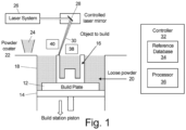
- Fig. 1 is a schematic of an exemplary, non-limiting LPBF additive manufacturing system 10.
- the LPBF system 10 can be used with a variety of build powders to produce a workpiece 16.
- the powder can be a metallic powder or polymeric powder.
- Metallic powders compatible with typical LPBF systems 10 include aluminum, aluminum alloys (e.g., aluminum-lithium alloys), titanium, nickel, nickel alloys, and other metals and alloys known in the art.
- Polymeric powders compatible with typical LPBF systems 10 include a wide variety of polymers as known in the art.
- a typical LPBF system 10 includes a build plate 12, a build station piston 14 that adjusts the height of the build plate 12, a workpiece or part 16 that is built on top of the build plate 12, a powder chamber 18 to contain loose, and unconsolidated build powder 20 that surrounds the workpiece 16.
- a typical LPBF system 10 also includes a powder coater 22 that distributes additional build powder 24 over the workpiece 16 after completion of each layer formed on the workpiece 16.
- a laser system 26 combined with a controlled laser mirror 28 directs a laser beam 30 onto loose build powder 20 to form a melt pool (not shown) that, when solidified, forms a layer of the workpiece 16.
- the build station piston 14 lowers the build plate 12 and workpiece 16 by a predetermined distance that corresponds to the desired thickness of the next layer of the workpiece 16.
- the powder coater 22 then moves across the top of the loose build powder 20 to distribute a layer of additional build powder 24 that will then be consolidated with the laser beam 30 to form the next layer of the workpiece 16.
- Controller 32 controls the height of the build plate 12 by moving the build station piston 14, which in turn controls the thickness of each layer of the workpiece 16. Controller 32 also controls the movement of the powder coater 22 as it distributes additional build powder 24 and the movement of the laser beam 30 as it forms the melt pool that consolidates loose build powder 20 to form each layer of the workpiece 16. For example, the controller 32 controls LPBF system 10 operating parameters, including:
- Controller 32 typically includes a reference database 34 and processor 36.
- Reference database 34 contains processing data relevant to the LPBF system 10, build powder to be used to produce the workpiece 16, and the specific work piece 16 to be produced.
- Processor 36 contains programming to interface with the reference database 34 to control the LPBF system 10 to products parts, such as workpiece 16, as is known to a person of ordinary skill in the art.
- Workpiece 16 can be a near-net-shaped part (i.e., initial production of the part that is very close to the final (net) shape).
- Controller 32 can also collect data from sensors used to monitor the LPBF process, including at least one neuromorphic sensor 38, which provides an asynchronous data stream indicative of visually observable changes to the LPBF process, including changes to the melt pool.
- the at least one neuromorphic sensor 38 can collect data from any portion of the observable electromagnetic spectrum associated with the LPBF process.
- the neuromorphic sensors 38 can be configured to collect data across a range of desirable wave lengths, including wave lengths commonly associated with the infrared band, the visible band, and the ultraviolet band as well as other bands of the electromagnetic spectrum.
- the neuromorphic sensors 38 Due to the high sampling rate (e.g., 1 MHz or 1,000,000 equivalent frames per second) of the neuromorphic sensors 38 compared with other image capture devices, such as high resolution cameras and high speed/ultra-high speed cameras, the neuromorphic sensors 38 have a microsecond temporal resolution that permits capture of data from very rapidly occurring events. In addition, the neuromorphic sensors 38 have a much higher dynamic range (e.g., 120 dB) compared with other image capture devices, allowing capture of data at a high resolution. Combining the high sampling rate with high resolution imaging allows the neuromorphic sensors 38 to produce a rich dataset for assessing the LPBF process.
- the high sampling rate e.g., 1 MHz or 1,000,000 equivalent frames per second
- the at least one neuromorphic sensor 38 which provides fast, high resolution asynchronous data can optionally be combined with at least one synchronous sensor 40 to capture additional data such as melt pool temperature, pressure, and other visual and environmental data.
- data from the at least one neuromorphic sensor 38 and the at least one synchronous sensor 40 can optionally be combined with the LPBF system 10 operating parameters discussed above, including:
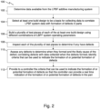
- Fig. 2 is a flow chart of a method 100 for correlate LPBF system data with the formation of defects in LPBF manufactured parts.
- a first step 102 the data available from the comprehensive data set described above are determined.
- at least one build design is selected to be a basis for collecting data to correlate LPBF system data with the formation of defects in LPBF manufactured parts.
- the at least one build design can be any build design deemed to be representative of parts to be built using the LPBF system. If desired, more than one build design (i.e., any number of build designs) can be selected for collecting data to correlate LPBF system data with the formation of defects in LPBF manufactured parts.
- step 106 At least a portion of the data identified in step 102 is collected as each of the plurality of test pieces is built.
- the data collected in step 106 can be reviewed as it is collected and, in any case, is recorded for analysis in later steps of the method 100.
- each of the plurality of test pieces are inspected to determine if any of the test pieces have defects including, but are not limited to, porosity, unfused powder, balling, cracking, warping, delamination, swelling, formation of humps and valleys, and other defects.
- the plurality of test pieces can be inspected for defects using any relevant inspection techniques including visual inspection, dye penetrant inspection, x-ray inspection (including CT/CAT scans), destructive inspection, and any other type of inspections that would be useful for identifying the presence of defects in the plurality of test pieces.
- any defects identified as a result of the inspection step 108 are assessed to determine when they formed during the build process and the likely cause of the defect.
- the data collected in step 106 are then reviewed to correlate data collected when the defects formed during the build process to the defects themselves.
- the correlated data are then reviewed to determine which of the LPBF operating system operating conditions, including melt pool conditions, that are observable with the at least one neuromorphic sensor 38 and the at least one synchronous sensor 40 can be used as criteria to indicate the formation of or potential formation of defects. Going forward, in step 112, the identified criteria to indicate the formation of or potential formation of defects can be provided to (e.g., coded into) the LPBF system controller 32 to provide a real time indication of the formation of or potential formation of defects during a build cycle.
- Fig. 3 is a flow chart of a method 200 for additive manufacturing of parts using a LPBF additive manufacturing system.
- a first step 202 an initial batch of build powder is provided to the LPBF system.
- a part is built at step 204 using selected LPBF system operating parameters.
- the selected LPBF system operating parameters can include any desired combination of laser beam power, velocity, spot size, build plate temperature, layer thickness, and laser hatching strategy including hatch distance, hatch delay time, and stripe width.
- Other LPBF system operating parameters can be selected as well.
- the part can be a complex near-net-shaped part or any other part desired to be made using the LPBF system.
- the data about the LPBF system operating conditions, including melt pool conditions are collected with the at least one neuromorphic sensor 38 and, optionally, the at least one synchronous sensor 40 and transmitted to the LPBF system controller 32 through means known in the art for transmitting signals from sensors to a controller.
- the LPBF system controller 32 processes data from the neuromorphic sensors 38 and, optionally, synchronous sensors 40 to determine whether conditions in the LPBF system, including at the melt pool, are suitable for the formation of or potential formation of defects.
- the controller 32 determines at step 206 that conditions are suitable for the formation of or potential formation of defects, the controller 32, at step 208, takes at least one predetermined mitigation action to mitigate the formation of or potential formation of defects.
- the mitigation action can be at least one of:
- the detection of the formation of or potential formation of defects and data about conditions in the LPBF system can be provided to an expert system, including an system that implements a machine learning or artificial intelligence algorithm (e.g., a reinforcement learning algorithm), to prescribe corrective actions to be taken in the next pass of the LPBF system.
- a machine learning or artificial intelligence algorithm e.g., a reinforcement learning algorithm
- the disclosed system and method uses asynchronous data collection from neuromorphic sensors to identify anomalies and instabilities in the melt pool that are associated with the formation of defects in the additively manufactured part. By identifying the formation of or potential formation of defects during the build process, certain defects can be mitigated during the build process or, if not suitable mitigation is available, the build process can be terminated or stopped early, avoiding the time and expense of completing a part known to be defective. Further, the use of the disclosed system and method can improve the repeatability of a build process to the point that parts made with the process can be certified for commercial use without elaborate inspection techniques, including, for example, computed tomography scans (CT or CAT scans.
- CT computed tomography scans
- a laser powder bed fusion (LPBF) additive manufacturing system comprising: a build plate; a build station piston configured to adjust the height of the build plate as a part is built on top of the build plate; a powder chamber configured to contain loose build powder, wherein the powder chamber surrounds the build plate; a laser system configured to direct a laser beam onto the loose build powder to form a melt pool, wherein when the melt pool forms a layer of the part as the melt pool solidifies and wherein as each layer of the part is formed the build station piston lowers the build plate and part by a predetermined distance corresponding to a desired thickness of a next layer of the part; a powder coater configured to distribute additional build powder over the part after completion of each layer of the part; a controller; at least one neuromorphic sensor configured to capture asynchronous data indicative of visually observable changes to the melt pool; and means to transmit to the controller the asynchronous data from the at least one neuromorphic sensor and, optionally, the synchronous data from the at least one synchronous sensor.
- LPBF laser
- the controller is configured to process the asynchronous data from the at least one neuromorphic sensor to determine whether conditions in the LPBF additive manufacturing system are suitable for formation of or protentional formation of defects in the part.
- the controller is further configured to take at least one predetermined mitigation action to mitigate the formation of or potential formation of defects in the part.
- the LPBF additive manufacturing system of the preceding paragraph can optionally include, additionally and/or alternatively, any one or more of the following features, configurations and/or additional elements.
- a further embodiment of the foregoing system further comprising at least one synchronous sensor configured to capture synchronous data that includes at least one of melt pool temperature and melt pool pressure, wherein the controller is configured to process the asynchronous data from the at least one neuromorphic sensor and the synchronous data from the at least one synchronous sensor to determine whether conditions in the LPBF additive manufacturing system are suitable for formation of or protentional formation of defects in the part.
- controller is further configured to process at least one of laser beam power, laser beam velocity, laser beam spot size, build plate temperature, layer thickness, laser hatch distance, laser hatch delay time, and laser hatch stripe width along with the asynchronous data from the at least one neuromorphic sensor and the synchronous data from the at least one synchronous sensor to determine whether conditions in the LPBF additive manufacturing system are suitable for the formation of or protentional formation of defects in the part.
- the at least one predetermined mitigation action is at least one of: notifying an operator of the formation of or potential formation of defects in the part; changing at least one LPBF system operating parameter for at least the next layer of the build process; reworking all or part of a layer in which the defect was detected; stopping the build process so the part can be reworked manually; and stopping the build process so the part can be scrapped.
- notifying an operator of the formation of or potential formation of defects includes providing a visual or aural alert.
- changing at least one LPBF additive manufacturing system operating parameter for at least the next layer of the build process includes changing at least one of laser beam power, laser beam velocity, laser beam spot size, build plate temperature, layer thickness, laser hatch distance, laser hatch delay time, and laser hatch stripe width.
- a method for correlating laser powder bed fusion (LPBF) additive manufacturing system data with formation of defects in LPBF manufactured parts comprising the steps of: determining data available from the LPBF additive manufacturing system; selecting at least one build design to be a basis for collecting data to correlate LPBF additive manufacturing system data with formation of defects in LPBF manufactured parts; building a plurality of test pieces of the at least one build design using a LPBF additive manufacturing system and collecting at least a portion of the data available from the LPBF additive manufacturing system as each of the plurality of test pieces is built; inspecting each of the plurality of test pieces to determine if any of the test pieces have defects; assessing any defects identified as a result of the inspection to determine when the defects formed during the build process and the likely cause of the defect; correlating data collected when the defects formed during the build process to the identified defects; determining which of the LPBF additive manufacturing system operating conditions that are observable with the at least one neuromorphic sensor and the at least one synchronous sensor can be used as criteria to indicate the formation of or potential formation of
- the LPBF additive manufacturing system of the preceding paragraph can optionally include, additionally and/or alternatively, any one or more of the following features, configurations and/or additional elements.
- a further embodiment of any of the foregoing methods, wherein building a plurality of test pieces of the at least one build design using a LPBF additive manufacturing system includes selecting LPBF additive manufacturing system operating parameters so the test pieces represent a range of LPBF additive manufacturing system operating parameters.
- a further embodiment of any of the foregoing methods, wherein building a plurality of test pieces of the at least one build design using a LPBF additive manufacturing system includes selecting LPBF additive manufacturing system operating parameters to induce the formation of defects in the plurality of test pieces.
- defects in the plurality of test pieces include one or more of porosity, unfused powder, balling, cracking, warping, delamination, swelling, and formation of humps and valleys.
- a further embodiment of any of the foregoing methods, wherein building a plurality of test pieces of the at least one build design using a LPBF additive manufacturing system includes selecting LPBF additive manufacturing system operating parameters so the test pieces represent a range of LPBF additive manufacturing system operating parameters.
- a further embodiment of any of the foregoing methods, wherein collecting at least a portion of the data available from the LPBF additive manufacturing system includes recording the data for analysis.
- a further embodiment of any of the foregoing methods, wherein inspecting each of the plurality of test pieces to determine if any of the test pieces have defects includes inspecting the test pieces by at least one of visual inspection, dye penetrant inspection, x-ray inspection (including CT/CAT scans), and destructive inspection.
- a method for additive manufacturing parts using a laser powder bed fusion (LPBF) additive manufacturing system comprising the steps of: providing to the LPBF additive manufacturing system an initial batch of build powder; building a part using selected LPBF additive manufacturing system operating parameters; collecting data about the LPBF additive manufacturing system operating conditions with at least one neuromorphic sensor and, optionally, at least one synchronous sensor; transmitting to a LPBF additive manufacturing system controller the data collected about the LPBF additive manufacturing system operating conditions with the at least one neuromorphic sensor and, optionally, the at least one synchronous sensor; processing, by the LPBF additive manufacturing system controller, the data collected about the LPBF additive manufacturing system operating conditions with the at least one neuromorphic sensor and, optionally, the at least one synchronous sensor to determine whether conditions in the LPBF additive manufacturing system are suitable for the formation of or protentional formation of defects; and if the controller determines that conditions are suitable for the formation of or potential formation of defects, taking, by the controller, at least one predetermined mitigation action to mitigate the formation of or potential formation of defects.
- the LPBF additive manufacturing system of the preceding paragraph can optionally include, additionally and/or alternatively, any one or more of the following features, configurations and/or additional elements.
- the selected LPBF additive manufacturing system operating parameters include at least one of laser beam power, laser beam velocity, laser beam spot size, build plate temperature, layer thickness, laser hatch distance, laser hatch delay time, and laser hatch stripe width.
- the at least one predetermined mitigation action is at least one of: notifying an operator of the formation of or potential formation of defects; changing at least one of the LPBF additive manufacturing system operating parameters for at least the next layer of the build process; reworking all or part of a layer in which the defect was detected; stopping the build process so the part can be reworked manually; and stopping the build process so the part can be scrapped.
- notifying an operator of the formation of or potential formation of defects includes providing a visual or aural alert.
- changing at least one LPBF additive manufacturing system operating parameter for at least the next layer of the build process includes changing at least one of laser beam power, laser velocity, laser spot size, build plate temperature, layer thickness, and laser hatch distance, laser hatch delay time, and laser hatch stripe width.
Landscapes
- Engineering & Computer Science (AREA)
- Chemical & Material Sciences (AREA)
- Materials Engineering (AREA)
- Manufacturing & Machinery (AREA)
- Automation & Control Theory (AREA)
- Plasma & Fusion (AREA)
- Physics & Mathematics (AREA)
- Analytical Chemistry (AREA)
- Optics & Photonics (AREA)
- Health & Medical Sciences (AREA)
- General Health & Medical Sciences (AREA)
- Toxicology (AREA)
- Powder Metallurgy (AREA)
Abstract
A laser powder bed fusion (LPBF) system (10) includes a build plate (12), a build station piston (14) configured to adjust the height of the build plate (12) as a part (16) is built on top of the build plate (12), and a powder chamber (18) configured to contain loose build powder (20), wherein the powder chamber (18) surrounds the build plate (12). The LPBF system (10) also includes a laser system (26) configured to direct a laser beam (30) onto the loose build powder (20) to form a melt pool, which forms a layer of the part (16) as the melt pool solidifies. As each layer of the part (16) is formed, the build station piston (14) lowers the build plate (12) and part (16) by a predetermined distance corresponding to a desired thickness of a next layer of the part (16). The LPBF system (10) further includes a powder coater (22) configured to distribute additional build powder (24) over the part (16) after completion of each layer of the part (16), a controller (32), at least one neuromorphic sensor (38) configured capture asynchronous data indicative of visually observable changes to the melt pool, optionally, at least one synchronous sensor (40) configured to capture synchronous data, and means to transmit to the controller (32) the asynchronous data and, optionally, the synchronous data. The controller (32) is configured to process the asynchronous data and, optionally, the synchronous data to determine whether conditions in the LPBF system (10) are suitable for formation of or protentional formation of defects in the part (16). The controller (32) is further configured to take at least one predetermined mitigation action to mitigate the formation of or potential formation of defects in the part (16).
Description
- The present disclosure relates generally to laser powder bed fusion additive manufacturing and, more particularly, to a method of monitoring a laser powder bed fusion additive manufacturing process.
- Laser powder bed fusion (LPBF) additive manufacturing is an additive manufacturing, or 3-D printing, technology that uses a laser to sinter or fuse metallic or polymeric particles together in a layer-by-layer process. LPBF is typically used as an industrial process to make near net shape parts. Some LPBF processes sinter the build powder particles, while others melt and fuse the build powder particles. LPBF is also known as direct metal laser sintering (DMLS).
- LPBF additive manufacturing processes are dynamic, high temperature, high energy processes in which conditions change rapidly as a laser scans a build powder bed to form a melt pool. The combination of rapidly changing conditions and high temperature/high energy create an environment in which defects can form in parts made with an LPBF additive manufacturing process. Because defects formed in such parts can be difficult to detect without elaborate inspection techniques, including, for example, computed tomography scans (CT or CAT scans), certifying parts made with an LPBF additive manufacturing process for commercial use can be a challenge.
- One aspect of this disclosure is directed to a laser powder bed fusion (LPBF) additive manufacturing system that includes a build plate, a build station piston configured to adjust the height of the build plate as a part is built on top of the build plate, and a powder chamber configured to contain loose build powder, wherein the powder chamber surrounds the build plate. The LPBF additive manufacturing system also includes a laser system configured to direct a laser beam onto the loose build powder to form a melt pool. The melt pool forms a layer of the part as the melt pool solidifies. As each layer of the part is formed, the build station piston lowers the build plate and part by a predetermined distance corresponding to a desired thickness of a next layer of the part. The LPBF additive manufacturing system further includes a powder coater configured to distribute additional build powder over the part after completion of each layer of the part, a controller, at least one neuromorphic sensor configured capture asynchronous data indicative of visually observable changes to the melt pool, optionally, at least one synchronous sensor configured to capture synchronous data that includes at least one of melt pool temperature and melt pool pressure, and means to transmit to the controller the asynchronous data from the at least one neuromorphic sensor and, optionally, the synchronous data from the at least one synchronous sensor. The controller is configured to process the asynchronous data from the at least one neuromorphic sensor and, optionally, the synchronous data from the at least one synchronous sensor to determine whether conditions in the LPBF additive manufacturing system are suitable for formation of or protentional formation of defects in the part. The controller is further configured to take at least one predetermined mitigation action to mitigate the formation of or potential formation of defects in the part.
- Another aspect of the disclosure is directed to a method for correlating laser powder bed fusion (LPBF) additive manufacturing system data with formation of defects in LPBF manufactured parts. The method includes determining data available from the LPBF additive manufacturing system, selecting at least one build design to be a basis for collecting data to correlate LPBF additive manufacturing system data with formation of defects in LPBF manufactured parts, and building a plurality of test pieces of the at least one build design using a LPBF additive manufacturing system and collecting at least a portion of the data available from the LPBF additive manufacturing system as each of the plurality of test pieces is built. The method also includes inspecting each of the plurality of test pieces to determine if any of the test pieces have defects, assessing any defects identified as a result of the inspection to determine when the defects formed during the build process and the likely cause of the defect, and correlating data collected when the defects formed during the build process to the identified defects. The method further includes determining which of the LPBF additive manufacturing system operating conditions that are observable with the at least one neuromorphic sensor and the at least one synchronous sensor can be used as criteria to indicate the formation of or potential formation of defects; and providing to a LPBF additive manufacturing system controller the identified criteria to indicate the formation of or potential formation of defects in a part, whereby the LPBF additive manufacturing system controller is configured to provide a real time indication of the formation of or potential formation of defects in the part during a build cycle.
- Yet another aspect of this disclosure is directed to a method for additive manufacturing parts using a laser powder bed fusion (LPBF) additive manufacturing system. The method includes the steps of providing to the LPBF additive manufacturing system an initial batch of build powder, building a part using selected LPBF additive manufacturing system operating parameters, and collecting data about the LPBF additive manufacturing system operating conditions with at least one neuromorphic sensor and, optionally, at least one synchronous sensor. The method also includes transmitting to a LPBF additive manufacturing system controller the data collected about the LPBF additive manufacturing system operating conditions with at least one neuromorphic sensor and, optionally, at least one synchronous sensor and processing, by the LPBF additive manufacturing system controller, the data collected about the LPBF additive manufacturing system operating conditions with the at least one neuromorphic sensor and, optionally, the at least one synchronous sensor to determine whether conditions in the LPBF additive manufacturing system are suitable for the formation of or protentional formation of defects. If the controller determines that conditions are suitable for the formation of or potential formation of defects, the controller takes at least one predetermined mitigation action to mitigate the formation of or potential formation of defects.
- Features of embodiments are set forth in the dependent claims.
-
-
Fig. 1 is a schematic of an exemplary laser powder bed fusion (LPBF) additive manufacturing system. -
Fig. 2 is a flow chart of a method for correlating LPBF system data with the formation of defects in LPBF manufactured parts. -
Fig. 3 is a flow chart of a method for additive manufacturing parts using a LPBF additive manufacturing system. - Laser powder bed fusion (LPBF) additive manufacturing is an option to make near net shape parts. The dynamic, high temperature, high energy processes conditions that are characteristic of LPBF additive manufacturing processes create an environment that is challenging to monitor using conventional techniques. For example, the rapid changes that occur in a LPBF melt pool cannot be captured readily using conventional high speed cameras due to frame rate limitations. Similarly, the high temperatures associated with the LPBF melt pool create a dynamic range challenge for high speed cameras. As a result, it is difficult or even impossible to detect the formation of defects in parts during manufacture using an LPBF additive manufacturing process. For the same reason, it has been difficult or even impossible to control the LPBF process to limit or prevent the formation of such defects.
- The relatively recent development of neuromorphic sensors, also known as event cameras, has created the possibility of monitoring LPBF additive manufacturing processes in real time. Neuromorphic sensors do not capture images using a shutter as conventional (frame) cameras do. Rather, neuromorphic sensors capture images as a collection of individual pixels that operate independently and asynchronously from all of the other pixels in the neuromorphic sensor. Each pixel reports changes in brightness as they occur and remains silent if there is no change in brightness. This feature allows neuromorphic sensors to have microsecond responsiveness and allows for a higher sampling rate that is possible using other techniques, such as high speed cameras.
- The asynchronous data collection from the neuromorphic sensors can be used to identify anomalies and instabilities in the melt pool, including anomalies associated with the formation of defects in the additively manufactured part. Defects known to occur in LPBF manufactured parts include porosity, unfused powder, balling, cracking, warping, delamination, swelling, formation of humps and valleys, and other defects. Data collected from neuromorphic sensors can be supplemented with data from other sensors compatible with the LPBF environment, such as laser sensors, voltage sensors, and other sensors to create a "sensor fusion" environment to provide a richer set of data for monitoring the LPBF process.
-
Fig. 1 is a schematic of an exemplary, non-limiting LPBF additive manufacturing system 10. The LPBF system 10 can be used with a variety of build powders to produce aworkpiece 16. For example, the powder can be a metallic powder or polymeric powder. Metallic powders compatible with typical LPBF systems 10 include aluminum, aluminum alloys (e.g., aluminum-lithium alloys), titanium, nickel, nickel alloys, and other metals and alloys known in the art. Polymeric powders compatible with typical LPBF systems 10 include a wide variety of polymers as known in the art. - A typical LPBF system 10 includes a
build plate 12, abuild station piston 14 that adjusts the height of thebuild plate 12, a workpiece orpart 16 that is built on top of thebuild plate 12, apowder chamber 18 to contain loose, andunconsolidated build powder 20 that surrounds theworkpiece 16. A typical LPBF system 10 also includes apowder coater 22 that distributesadditional build powder 24 over theworkpiece 16 after completion of each layer formed on theworkpiece 16. Alaser system 26 combined with a controlledlaser mirror 28 directs alaser beam 30 ontoloose build powder 20 to form a melt pool (not shown) that, when solidified, forms a layer of theworkpiece 16. As each layer of theworkpiece 16 is formed, thebuild station piston 14 lowers thebuild plate 12 andworkpiece 16 by a predetermined distance that corresponds to the desired thickness of the next layer of theworkpiece 16. Thepowder coater 22 then moves across the top of theloose build powder 20 to distribute a layer ofadditional build powder 24 that will then be consolidated with thelaser beam 30 to form the next layer of theworkpiece 16. -
Controller 32 controls the height of thebuild plate 12 by moving thebuild station piston 14, which in turn controls the thickness of each layer of theworkpiece 16.Controller 32 also controls the movement of thepowder coater 22 as it distributesadditional build powder 24 and the movement of thelaser beam 30 as it forms the melt pool that consolidatesloose build powder 20 to form each layer of theworkpiece 16. For example, thecontroller 32 controls LPBF system 10 operating parameters, including: - (1) laser beam power, velocity and spot size, build plate temperature, and layer thickness;
- (2) temperature-dependent thermophysical properties of the powder;
- (3) feedstock properties including average powder particle size; and
- (4) laser hatching strategy including hatch distance, hatch delay time, and stripe width.
-
Controller 32 typically includes areference database 34 andprocessor 36.Reference database 34 contains processing data relevant to the LPBF system 10, build powder to be used to produce theworkpiece 16, and thespecific work piece 16 to be produced.Processor 36 contains programming to interface with thereference database 34 to control the LPBF system 10 to products parts, such asworkpiece 16, as is known to a person of ordinary skill in the art.Workpiece 16 can be a near-net-shaped part (i.e., initial production of the part that is very close to the final (net) shape). -
Controller 32 can also collect data from sensors used to monitor the LPBF process, including at least oneneuromorphic sensor 38, which provides an asynchronous data stream indicative of visually observable changes to the LPBF process, including changes to the melt pool. The at least oneneuromorphic sensor 38, can collect data from any portion of the observable electromagnetic spectrum associated with the LPBF process. For example, theneuromorphic sensors 38 can be configured to collect data across a range of desirable wave lengths, including wave lengths commonly associated with the infrared band, the visible band, and the ultraviolet band as well as other bands of the electromagnetic spectrum. Due to the high sampling rate (e.g., 1 MHz or 1,000,000 equivalent frames per second) of theneuromorphic sensors 38 compared with other image capture devices, such as high resolution cameras and high speed/ultra-high speed cameras, theneuromorphic sensors 38 have a microsecond temporal resolution that permits capture of data from very rapidly occurring events. In addition, theneuromorphic sensors 38 have a much higher dynamic range (e.g., 120 dB) compared with other image capture devices, allowing capture of data at a high resolution. Combining the high sampling rate with high resolution imaging allows theneuromorphic sensors 38 to produce a rich dataset for assessing the LPBF process. - The at least one
neuromorphic sensor 38, which provides fast, high resolution asynchronous data can optionally be combined with at least onesynchronous sensor 40 to capture additional data such as melt pool temperature, pressure, and other visual and environmental data. Similarly, data from the at least oneneuromorphic sensor 38 and the at least onesynchronous sensor 40 can optionally be combined with the LPBF system 10 operating parameters discussed above, including: - (1) laser beam power, laser beam velocity, laser beam spot size, laser current and voltage, build plate temperature, and layer thickness;
- (2) temperature-dependent thermophysical properties of the powder;
- (3) feedstock properties including average powder particle size; and
- (4) laser hatching strategy including hatch distance, hatch delay time, and stripe width to create a comprehensive data set with which the operation of the LPBF system 10 can be monitored and assessed. The at least one
synchronous sensor 40 can be one or more of a temperature sensor, a pressure sensor, a voltage sensor, a conventional high speed camera, a conventional high resolution camera, a laser scanner, and any other synchronous sensor that an provide useful data. The combination of asynchronous data from the at least oneneuromorphic sensor 38 and selected synchronous data points from the at least onesynchronous sensor 40, and LPBF system 10 operating parameters can be combined to provide information how much time the laser spends at a particular location for a particular layer of the build to correlate laser location and time data with information about identified defects. The objective is to combine event data with time-series data or visual data to get a more comprehensive, correlated data set with which to evaluate the formation of or potential formation of defects in LPBF manufactured parts. - With the availability of a comprehensive data set, the method depicted in
Fig. 2 can be used to correlate LPBF system 10 data with the formation of defects in LPBF manufactured parts. The defects include, but are not limited to, porosity, unfused powder, balling, cracking, warping, delamination, swelling, formation of humps and valleys, and other defects.Fig. 2 is a flow chart of amethod 100 for correlate LPBF system data with the formation of defects in LPBF manufactured parts. As afirst step 102, the data available from the comprehensive data set described above are determined. Next, atstep 104 at least one build design is selected to be a basis for collecting data to correlate LPBF system data with the formation of defects in LPBF manufactured parts. The at least one build design can be any build design deemed to be representative of parts to be built using the LPBF system. If desired, more than one build design (i.e., any number of build designs) can be selected for collecting data to correlate LPBF system data with the formation of defects in LPBF manufactured parts. - At
step 106, a plurality of test pieces of the at least one build design are built using a LPBF system. Different combinations of LPBF system operating parameters should be selected so the test pieces represent a range of anticipated LPBF system operating parameters for the types of parts for data to correlate LPBF system data with the formation of defects in LPBF manufactured parts will be collected. If desired, the LPBF system operating conditions can be selected to induce the formation of defects including, but are not limited to, porosity, unfused powder, balling, cracking, warping, delamination, swelling, formation of humps and valleys, and other defects. Inducing defects into the plurality of test pieces can be useful in later correlating data with the formation of such defects. Duringstep 106, at least a portion of the data identified instep 102 is collected as each of the plurality of test pieces is built. The data collected instep 106 can be reviewed as it is collected and, in any case, is recorded for analysis in later steps of themethod 100. - At
step 108, each of the plurality of test pieces are inspected to determine if any of the test pieces have defects including, but are not limited to, porosity, unfused powder, balling, cracking, warping, delamination, swelling, formation of humps and valleys, and other defects. The plurality of test pieces can be inspected for defects using any relevant inspection techniques including visual inspection, dye penetrant inspection, x-ray inspection (including CT/CAT scans), destructive inspection, and any other type of inspections that would be useful for identifying the presence of defects in the plurality of test pieces. - In
step 110, any defects identified as a result of theinspection step 108 are assessed to determine when they formed during the build process and the likely cause of the defect. The data collected instep 106 are then reviewed to correlate data collected when the defects formed during the build process to the defects themselves. The correlated data are then reviewed to determine which of the LPBF operating system operating conditions, including melt pool conditions, that are observable with the at least oneneuromorphic sensor 38 and the at least onesynchronous sensor 40 can be used as criteria to indicate the formation of or potential formation of defects. Going forward, instep 112, the identified criteria to indicate the formation of or potential formation of defects can be provided to (e.g., coded into) theLPBF system controller 32 to provide a real time indication of the formation of or potential formation of defects during a build cycle. -
Fig. 3 is a flow chart of amethod 200 for additive manufacturing of parts using a LPBF additive manufacturing system. As afirst step 202, an initial batch of build powder is provided to the LPBF system. Once the initial batch of build powder has been provided to the LPBF system, a part is built atstep 204 using selected LPBF system operating parameters. The selected LPBF system operating parameters can include any desired combination of laser beam power, velocity, spot size, build plate temperature, layer thickness, and laser hatching strategy including hatch distance, hatch delay time, and stripe width. Other LPBF system operating parameters can be selected as well. The part can be a complex near-net-shaped part or any other part desired to be made using the LPBF system. - During
step 206, the data about the LPBF system operating conditions, including melt pool conditions, are collected with the at least oneneuromorphic sensor 38 and, optionally, the at least onesynchronous sensor 40 and transmitted to theLPBF system controller 32 through means known in the art for transmitting signals from sensors to a controller. TheLPBF system controller 32 processes data from theneuromorphic sensors 38 and, optionally,synchronous sensors 40 to determine whether conditions in the LPBF system, including at the melt pool, are suitable for the formation of or potential formation of defects. - If the
controller 32 determines atstep 206 that conditions are suitable for the formation of or potential formation of defects, thecontroller 32, atstep 208, takes at least one predetermined mitigation action to mitigate the formation of or potential formation of defects. The mitigation action can be at least one of: - notifying an operator of the formation of or potential formation of defects by suitable means, including but not limited to providing a visual or aural alert;
- taking predetermined steps to mitigate the formation of or potential formation of defects, including but not limited to changing at least one of the LPBF system operating parameters discussed above for at least the next layer of the build process;
- taking predetermined steps correct a defect whose formation was detected by the
controller 32, including but not limited to reworking all or part of a layer in which the defect was detected; - stopping the build process so the part can be reworked manually or scrapped as deemed appropriate;
- any other mitigation step that is deemed to be appropriate.
- Additionally, the detection of the formation of or potential formation of defects and data about conditions in the LPBF system can be provided to an expert system, including an system that implements a machine learning or artificial intelligence algorithm (e.g., a reinforcement learning algorithm), to prescribe corrective actions to be taken in the next pass of the LPBF system.
- The disclosed system and method uses asynchronous data collection from neuromorphic sensors to identify anomalies and instabilities in the melt pool that are associated with the formation of defects in the additively manufactured part. By identifying the formation of or potential formation of defects during the build process, certain defects can be mitigated during the build process or, if not suitable mitigation is available, the build process can be terminated or stopped early, avoiding the time and expense of completing a part known to be defective. Further, the use of the disclosed system and method can improve the repeatability of a build process to the point that parts made with the process can be certified for commercial use without elaborate inspection techniques, including, for example, computed tomography scans (CT or CAT scans.
- The following are non-exclusive descriptions of possible embodiments of the present invention.
- A laser powder bed fusion (LPBF) additive manufacturing system, comprising: a build plate; a build station piston configured to adjust the height of the build plate as a part is built on top of the build plate; a powder chamber configured to contain loose build powder, wherein the powder chamber surrounds the build plate; a laser system configured to direct a laser beam onto the loose build powder to form a melt pool, wherein when the melt pool forms a layer of the part as the melt pool solidifies and wherein as each layer of the part is formed the build station piston lowers the build plate and part by a predetermined distance corresponding to a desired thickness of a next layer of the part; a powder coater configured to distribute additional build powder over the part after completion of each layer of the part; a controller; at least one neuromorphic sensor configured to capture asynchronous data indicative of visually observable changes to the melt pool; and means to transmit to the controller the asynchronous data from the at least one neuromorphic sensor and, optionally, the synchronous data from the at least one synchronous sensor. The controller is configured to process the asynchronous data from the at least one neuromorphic sensor to determine whether conditions in the LPBF additive manufacturing system are suitable for formation of or protentional formation of defects in the part. The controller is further configured to take at least one predetermined mitigation action to mitigate the formation of or potential formation of defects in the part.
- The LPBF additive manufacturing system of the preceding paragraph can optionally include, additionally and/or alternatively, any one or more of the following features, configurations and/or additional elements.
- A further embodiment of the foregoing system, further comprising at least one synchronous sensor configured to capture synchronous data that includes at least one of melt pool temperature and melt pool pressure, wherein the controller is configured to process the asynchronous data from the at least one neuromorphic sensor and the synchronous data from the at least one synchronous sensor to determine whether conditions in the LPBF additive manufacturing system are suitable for formation of or protentional formation of defects in the part.
- A further embodiment of any of the foregoing systems, wherein the controller is further configured to process at least one of laser beam power, laser beam velocity, laser beam spot size, build plate temperature, layer thickness, laser hatch distance, laser hatch delay time, and laser hatch stripe width along with the asynchronous data from the at least one neuromorphic sensor and the synchronous data from the at least one synchronous sensor to determine whether conditions in the LPBF additive manufacturing system are suitable for the formation of or protentional formation of defects in the part.
- A further embodiment of any of the foregoing systems, wherein the at least one predetermined mitigation action is at least one of: notifying an operator of the formation of or potential formation of defects in the part; changing at least one LPBF system operating parameter for at least the next layer of the build process; reworking all or part of a layer in which the defect was detected; stopping the build process so the part can be reworked manually; and stopping the build process so the part can be scrapped.
- A further embodiment of the foregoing system, wherein notifying an operator of the formation of or potential formation of defects includes providing a visual or aural alert.
- A further embodiment of the foregoing system, wherein changing at least one LPBF additive manufacturing system operating parameter for at least the next layer of the build process includes changing at least one of laser beam power, laser beam velocity, laser beam spot size, build plate temperature, layer thickness, laser hatch distance, laser hatch delay time, and laser hatch stripe width.
- A method for correlating laser powder bed fusion (LPBF) additive manufacturing system data with formation of defects in LPBF manufactured parts, comprising the steps of: determining data available from the LPBF additive manufacturing system; selecting at least one build design to be a basis for collecting data to correlate LPBF additive manufacturing system data with formation of defects in LPBF manufactured parts; building a plurality of test pieces of the at least one build design using a LPBF additive manufacturing system and collecting at least a portion of the data available from the LPBF additive manufacturing system as each of the plurality of test pieces is built; inspecting each of the plurality of test pieces to determine if any of the test pieces have defects; assessing any defects identified as a result of the inspection to determine when the defects formed during the build process and the likely cause of the defect; correlating data collected when the defects formed during the build process to the identified defects; determining which of the LPBF additive manufacturing system operating conditions that are observable with the at least one neuromorphic sensor and the at least one synchronous sensor can be used as criteria to indicate the formation of or potential formation of defects; and providing to a LPBF additive manufacturing system controller the identified criteria to indicate the formation of or potential formation of defects in a part, whereby the LPBF additive manufacturing system controller is configured to provide a real time indication of the formation of or potential formation of defects in the part during a build cycle.
- The LPBF additive manufacturing system of the preceding paragraph can optionally include, additionally and/or alternatively, any one or more of the following features, configurations and/or additional elements.
- A further embodiment of the foregoing method, wherein the build design is representative of parts to be built using the LPBF additive manufacturing system.
- A further embodiment of any of the foregoing methods, wherein building a plurality of test pieces of the at least one build design using a LPBF additive manufacturing system includes selecting LPBF additive manufacturing system operating parameters so the test pieces represent a range of LPBF additive manufacturing system operating parameters.
- A further embodiment of any of the foregoing methods, wherein building a plurality of test pieces of the at least one build design using a LPBF additive manufacturing system includes selecting LPBF additive manufacturing system operating parameters to induce the formation of defects in the plurality of test pieces.
- A further embodiment of any of the foregoing methods, wherein the defects in the plurality of test pieces include one or more of porosity, unfused powder, balling, cracking, warping, delamination, swelling, and formation of humps and valleys.
- A further embodiment of any of the foregoing methods, wherein building a plurality of test pieces of the at least one build design using a LPBF additive manufacturing system includes selecting LPBF additive manufacturing system operating parameters so the test pieces represent a range of LPBF additive manufacturing system operating parameters.
- A further embodiment of any of the foregoing methods, wherein collecting at least a portion of the data available from the LPBF additive manufacturing system includes recording the data for analysis.
- A further embodiment of any of the foregoing methods, wherein inspecting each of the plurality of test pieces to determine if any of the test pieces have defects, includes inspecting the test pieces by at least one of visual inspection, dye penetrant inspection, x-ray inspection (including CT/CAT scans), and destructive inspection.
- A method for additive manufacturing parts using a laser powder bed fusion (LPBF) additive manufacturing system, comprising the steps of: providing to the LPBF additive manufacturing system an initial batch of build powder; building a part using selected LPBF additive manufacturing system operating parameters; collecting data about the LPBF additive manufacturing system operating conditions with at least one neuromorphic sensor and, optionally, at least one synchronous sensor; transmitting to a LPBF additive manufacturing system controller the data collected about the LPBF additive manufacturing system operating conditions with the at least one neuromorphic sensor and, optionally, the at least one synchronous sensor; processing, by the LPBF additive manufacturing system controller, the data collected about the LPBF additive manufacturing system operating conditions with the at least one neuromorphic sensor and, optionally, the at least one synchronous sensor to determine whether conditions in the LPBF additive manufacturing system are suitable for the formation of or protentional formation of defects; and if the controller determines that conditions are suitable for the formation of or potential formation of defects, taking, by the controller, at least one predetermined mitigation action to mitigate the formation of or potential formation of defects.
- The LPBF additive manufacturing system of the preceding paragraph can optionally include, additionally and/or alternatively, any one or more of the following features, configurations and/or additional elements.
- A further embodiment of the foregoing method, wherein the selected LPBF additive manufacturing system operating parameters include at least one of laser beam power, laser beam velocity, laser beam spot size, build plate temperature, layer thickness, laser hatch distance, laser hatch delay time, and laser hatch stripe width.
- A further embodiment of any of the foregoing methods, wherein the at least one predetermined mitigation action is at least one of: notifying an operator of the formation of or potential formation of defects; changing at least one of the LPBF additive manufacturing system operating parameters for at least the next layer of the build process; reworking all or part of a layer in which the defect was detected; stopping the build process so the part can be reworked manually; and stopping the build process so the part can be scrapped.
- A further embodiment of the foregoing method, wherein notifying an operator of the formation of or potential formation of defects includes providing a visual or aural alert.
- A further embodiment of the foregoing method, wherein changing at least one LPBF additive manufacturing system operating parameter for at least the next layer of the build process includes changing at least one of laser beam power, laser velocity, laser spot size, build plate temperature, layer thickness, and laser hatch distance, laser hatch delay time, and laser hatch stripe width.
- While the invention has been described with reference to an exemplary embodiment(s), it will be understood by those skilled in the art that various changes may be made and equivalents may be substituted for elements thereof without departing from the scope of the invention. In addition, many modifications may be made to adapt a particular situation or material to the teachings of the invention without departing from the essential scope thereof. Therefore, it is intended that the invention not be limited to the particular embodiment(s) disclosed, but that the invention will include all embodiments falling within the scope of the appended claims.
Claims (15)
- A laser powder bed fusion (LPBF) additive manufacturing system (10), comprising:a build plate (12);a build station piston (14) configured to adjust the height of the build plate (12) as a part (16) is built on top of the build plate (12);a powder chamber (18) configured to contain loose build powder (20), wherein the powder chamber (18) surrounds the build plate (12);a laser system (26) configured to direct a laser beam (30) onto the loose build powder (20) to form a melt pool, wherein when the melt pool forms a layer of the part (16) as the melt pool solidifies and wherein as each layer of the part (16) is formed the build station piston (14) lowers the build plate (12) and part (16) by a predetermined distance corresponding to a desired thickness of a next layer of the part (16);a powder coater (22) configured to distribute additional build powder (24) over the part (16) after completion of each layer of the part (16);a controller (32);at least one neuromorphic sensor (38) configured to capture asynchronous data indicative of visually observable changes to the melt pool; andmeans to transmit to the controller the asynchronous data from the at least one neuromorphic sensor (38) and, optionally, the synchronous data from the at least one synchronous sensor (40);wherein the controller (32) is configured to process the asynchronous data from the at least one neuromorphic sensor (38) to determine whether conditions in the LPBF additive manufacturing system (10) are suitable for formation of or protentional formation of defects in the part (16); andwherein the controller (32) is further configured to take at least one predetermined mitigation action to mitigate the formation of or potential formation of defects in the part (16).
- The system of claim 1, further comprising at least one synchronous sensor (40) configured to capture synchronous data that includes at least one of melt pool temperature and melt pool pressure, wherein the controller (32) is configured to process the asynchronous data from the at least one neuromorphic sensor (38) and the synchronous data from the at least one synchronous sensor (40) to determine whether conditions in the LPBF additive manufacturing system (10) are suitable for formation of or protentional formation of defects in the part (16).
- The system of claim 1 or 2, wherein the controller (32) is further configured to process at least one of laser beam power, laser beam velocity, laser beam spot size, build plate temperature, layer thickness, laser hatch distance, laser hatch delay time, and laser hatch stripe width along with the asynchronous data from the at least one neuromorphic sensor (38) and the synchronous data from the at least one synchronous sensor (40) to determine whether conditions in the LPBF additive manufacturing system (10) are suitable for the formation of or protentional formation of defects in the part (16).
- The system of any preceding claim, wherein the at least one predetermined mitigation action is at least one of:notifying an operator of the formation of or potential formation of defects in the part (16) by providing a visual or aural alert;changing at least one LPBF system operating parameter for at least the next layer of the build process;reworking all or part of a layer in which the defect was detected;stopping the build process so the part (16) can be reworked manually; andstopping the build process so the part (16) can be scrapped.
- The system of claim 4, wherein changing at least one LPBF additive manufacturing system operating parameter for at least the next layer of the build process includes changing at least one of laser beam power, laser beam velocity, laser beam spot size, build plate temperature, layer thickness, laser hatch distance, laser hatch delay time, and laser hatch stripe width.
- A method for correlating laser powder bed fusion (LPBF) additive manufacturing system data with formation of defects in LPBF manufactured parts (16), comprising the steps of:determining data available from the LPBF additive manufacturing system (10);selecting at least one build design to be a basis for collecting data to correlate LPBF additive manufacturing system data with formation of defects in LPBF manufactured parts (16);building a plurality of test pieces (16) of the at least one build design using a LPBF additive manufacturing system (10) and collecting at least a portion of the data available from the LPBF additive manufacturing system (10) as each of the plurality of test pieces (16) is built;inspecting each of the plurality of test pieces (16) to determine if any of the test pieces (16) have defects;assessing any defects identified as a result of the inspection to determine when the defects formed during the build process and the likely cause of the defect;correlating data collected when the defects formed during the build process to the identified defects;determining which of the LPBF additive manufacturing system operating conditions that are observable with the at least one neuromorphic sensor (38) and the at least one synchronous sensor (40) can be used as criteria to indicate the formation of or potential formation of defects; andproviding to a LPBF additive manufacturing system controller (32) the identified criteria to indicate the formation of or potential formation of defects in a part (16), whereby the LPBF additive manufacturing system controller (32) is configured to provide a real time indication of the formation of or potential formation of defects in the part (16) during a build cycle.
- The method of claim 6, wherein the build design is representative of parts (16) to be built using the LPBF additive manufacturing system (10).
- The method of claim 6 or 7, wherein building a plurality of test pieces (16) of the at least one build design using a LPBF additive manufacturing system (10) includes selecting LPBF additive manufacturing system operating parameters so the test pieces (16) represent a range of LPBF additive manufacturing system operating parameters.
- The method of any of claims 6 to 8, wherein building a plurality of test pieces (16) of the at least one build design using a LPBF additive manufacturing system (10) includes selecting LPBF additive manufacturing system operating parameters to induce the formation of defects in the plurality of test pieces (16).
- The method of claim 9, wherein the defects in the plurality of test pieces (16) include one or more of porosity, unfused powder, balling, cracking, warping, delamination, swelling, and formation of humps and valleys.
- The method of any of claims 6 to 10, wherein collecting at least a portion of the data available from the LPBF additive manufacturing system (10) includes recording the data for analysis.
- The method of any of claims 6 to 11, wherein inspecting each of the plurality of test pieces (16) to determine if any of the test pieces (16) have defects, includes inspecting the test pieces (16) by at least one of visual inspection, dye penetrant inspection, x-ray inspection (including CT/CAT scans), and destructive inspection.
- A method for additive manufacturing parts (16) using a laser powder bed fusion (LPBF) additive manufacturing system (10), comprising the steps of:providing to the LPBF additive manufacturing system (10) an initial batch of build powder (20);building a part (16) using selected LPBF additive manufacturing system operating parameters;collecting data about the LPBF additive manufacturing system operating conditions with at least one neuromorphic sensor (38) and, optionally, at least one synchronous sensor (40);transmitting to a LPBF additive manufacturing system controller (32) the data collected about the LPBF additive manufacturing system operating conditions with the at least one neuromorphic sensor (38) and, optionally, the at least one synchronous sensor (40);processing, by the LPBF additive manufacturing system controller (32), the data collected about the LPBF additive manufacturing system operating conditions with the at least one neuromorphic sensor (38) and, optionally, the at least one synchronous sensor (40) to determine whether conditions in the LPBF additive manufacturing system (20) are suitable for the formation of or protentional formation of defects; andif the controller (32) determines that conditions are suitable for the formation of or potential formation of defects, taking, by the controller (32), at least one predetermined mitigation action to mitigate the formation of or potential formation of defects.
- The method of claim 13, wherein the selected LPBF additive manufacturing system operating parameters include at least one of laser beam power, laser beam velocity, laser beam spot size, build plate temperature, layer thickness, laser hatch distance, laser hatch delay time, and laser hatch stripe width.
- The method of claim 13 or 14, wherein the at least one predetermined mitigation action is at least one of:notifying an operator of the formation of or potential formation of defects by providing a visual or aural alert;changing at least one of the LPBF additive manufacturing system operating parameters for at least the next layer of the build process by changing at least one of laser beam power, laser velocity, laser spot size, build plate temperature, layer thickness, and laser hatch distance, laser hatch delay time, and laser hatch stripe width;reworking all or part (16) of a layer in which the defect was detected;stopping the build process so the part (16) can be reworked manually; andstopping the build process so the part (16) can be scrapped.
Applications Claiming Priority (1)
| Application Number | Priority Date | Filing Date | Title |
|---|---|---|---|
| US18/345,848 US20250001506A1 (en) | 2023-06-30 | 2023-06-30 | Melt pool process using neuromorphic sensors |
Publications (1)
| Publication Number | Publication Date |
|---|---|
| EP4487983A1 true EP4487983A1 (en) | 2025-01-08 |
Family
ID=91738066
Family Applications (1)
| Application Number | Title | Priority Date | Filing Date |
|---|---|---|---|
| EP24185496.7A Pending EP4487983A1 (en) | 2023-06-30 | 2024-06-28 | Melt pool process using neuromorphic sensors |
Country Status (2)
| Country | Link |
|---|---|
| US (1) | US20250001506A1 (en) |
| EP (1) | EP4487983A1 (en) |
Citations (4)
| Publication number | Priority date | Publication date | Assignee | Title |
|---|---|---|---|---|
| WO2020191263A1 (en) * | 2019-03-21 | 2020-09-24 | General Electric Company | In-situ monitoring system assisted material and parameter development for additive manufacturing |
| DE102020205640A1 (en) * | 2020-05-05 | 2021-11-11 | Robert Bosch Gesellschaft mit beschränkter Haftung | Monitoring device for a manufacturing plant, manufacturing plant and process |
| WO2024046520A1 (en) * | 2022-09-02 | 2024-03-07 | Fraunhofer-Gesellschaft zur Förderung der angewandten Forschung eingetragener Verein | Method for the additive manufacture of a component, control system for controlling a method for the additive manufacture of a component, and manufacturing system |
| GB2623964A (en) * | 2022-10-31 | 2024-05-08 | Donaa Ltd | Vision system and software detecting defects in real-time during additive manufacturing. |
Family Cites Families (4)
| Publication number | Priority date | Publication date | Assignee | Title |
|---|---|---|---|---|
| WO2021058216A1 (en) * | 2019-09-25 | 2021-04-01 | SLM Solutions Group AG | Technique for analyzing sensor data in powder bed additive manufacturing |
| DE102020205637A1 (en) * | 2020-05-05 | 2021-11-11 | Robert Bosch Gesellschaft mit beschränkter Haftung | Monitoring device, joining device with monitoring device and method |
| EP4056375A1 (en) * | 2021-03-11 | 2022-09-14 | HP Scitex Ltd. | Printer performance levels |
| JP7716335B2 (en) * | 2021-12-28 | 2025-07-31 | 株式会社日立製作所 | Additive manufacturing condition search device and additive manufacturing condition search method |
-
2023
- 2023-06-30 US US18/345,848 patent/US20250001506A1/en active Pending
-
2024
- 2024-06-28 EP EP24185496.7A patent/EP4487983A1/en active Pending
Patent Citations (4)
| Publication number | Priority date | Publication date | Assignee | Title |
|---|---|---|---|---|
| WO2020191263A1 (en) * | 2019-03-21 | 2020-09-24 | General Electric Company | In-situ monitoring system assisted material and parameter development for additive manufacturing |
| DE102020205640A1 (en) * | 2020-05-05 | 2021-11-11 | Robert Bosch Gesellschaft mit beschränkter Haftung | Monitoring device for a manufacturing plant, manufacturing plant and process |
| WO2024046520A1 (en) * | 2022-09-02 | 2024-03-07 | Fraunhofer-Gesellschaft zur Förderung der angewandten Forschung eingetragener Verein | Method for the additive manufacture of a component, control system for controlling a method for the additive manufacture of a component, and manufacturing system |
| GB2623964A (en) * | 2022-10-31 | 2024-05-08 | Donaa Ltd | Vision system and software detecting defects in real-time during additive manufacturing. |
Non-Patent Citations (1)
| Title |
|---|
| M L VLASEA ET AL: "DEVELOPMENT OF POWDER BED FUSION ADDITIVE MANUFACTURING TEST BED FOR ENHANCED REAL-TIME PROCESS CONTROL", 31 December 2015 (2015-12-31), XP055312433, Retrieved from the Internet <URL:http://sffsymposium.engr.utexas.edu/sites/default/files/2015/2015-42-Vlasea.pdf> [retrieved on 20161019] * |
Also Published As
| Publication number | Publication date |
|---|---|
| US20250001506A1 (en) | 2025-01-02 |
Similar Documents
| Publication | Publication Date | Title |
|---|---|---|
| Mitchell et al. | Linking pyrometry to porosity in additively manufactured metals | |
| JP7704774B2 (en) | Method for in-situ inspection of weld quality - Patents.com | |
| US20230042539A1 (en) | Additive manufacturing method and apparatus | |
| Yang et al. | Investigation of deep learning for real-time melt pool classification in additive manufacturing | |
| Wu et al. | In situ monitoring methods for selective laser melting additive manufacturing process based on images—A review | |
| Sreedhar et al. | Automatic defect identification using thermal image analysis for online weld quality monitoring | |
| EP2964449B1 (en) | Method and device for evaluating the quality of a component produced by means of an additive laser sintering and/or laser melting method | |
| US20160098825A1 (en) | Feature extraction method and system for additive manufacturing | |
| Grasso et al. | Data fusion methods for statistical process monitoring and quality characterization in metal additive manufacturing | |
| EP2942132B1 (en) | Data fusion from sensors for process control of additive manufacturing from powders | |
| US11354456B2 (en) | Method of providing a dataset for the additive manufacture and corresponding quality control method | |
| US20170136574A1 (en) | Method and device for the quality assurance of at least one component during the production thereof by a generative production process | |
| US20130314504A1 (en) | Method and device for imaging at least one three-dimensional component | |
| EP3659727A1 (en) | Method for automatic identification of material deposition deficiencies during an additive manufacturing process and manufacturing device | |
| JP7318825B2 (en) | Laminate-molded article defect prediction method and laminate-molded article manufacturing method | |
| EP3666423A1 (en) | Systems and methods for monitoring powder spreading in additive manufacturing systems | |
| JP7428197B2 (en) | Steel plate shape discrimination method, shape measurement method, shape control method, manufacturing method, shape discrimination model generation method, and shape discrimination device | |
| KR102847646B1 (en) | Laser melt pool analyzing device using short wavelength bands and its analyzing method | |
| Colosimo et al. | On-machine measurement, monitoring and control | |
| Moshiri et al. | Performance evaluation of in-situ near-infrared melt pool monitoring during laser powder bed fusion | |
| Dickins | Design of a multi-sensor in-situ inspection system for additive manufacturing | |
| Barrett et al. | Low cost, high speed stereovision for spatter tracking in laser powder bed fusion | |
| JP2023066391A (en) | Method and apparatus for monitoring laser processing processes by speckle photometry | |
| US20250001506A1 (en) | Melt pool process using neuromorphic sensors | |
| Zhang et al. | Multiscale basis modeling of 3D melt-pool morphological variations for manufacturing process monitoring |
Legal Events
| Date | Code | Title | Description |
|---|---|---|---|
| PUAI | Public reference made under article 153(3) epc to a published international application that has entered the european phase |
Free format text: ORIGINAL CODE: 0009012 |
|
| STAA | Information on the status of an ep patent application or granted ep patent |
Free format text: STATUS: THE APPLICATION HAS BEEN PUBLISHED |
|
| AK | Designated contracting states |
Kind code of ref document: A1 Designated state(s): AL AT BE BG CH CY CZ DE DK EE ES FI FR GB GR HR HU IE IS IT LI LT LU LV MC ME MK MT NL NO PL PT RO RS SE SI SK SM TR |
|
| STAA | Information on the status of an ep patent application or granted ep patent |
Free format text: STATUS: REQUEST FOR EXAMINATION WAS MADE |
|
| 17P | Request for examination filed |
Effective date: 20250703 |