EP4487961A1 - Centrifuge, rotor for a centrifuge and drive head for a centrifuge - Google Patents
Centrifuge, rotor for a centrifuge and drive head for a centrifuge Download PDFInfo
- Publication number
- EP4487961A1 EP4487961A1 EP23183336.9A EP23183336A EP4487961A1 EP 4487961 A1 EP4487961 A1 EP 4487961A1 EP 23183336 A EP23183336 A EP 23183336A EP 4487961 A1 EP4487961 A1 EP 4487961A1
- Authority
- EP
- European Patent Office
- Prior art keywords
- rotor
- eccentric mass
- mass body
- drive
- drive element
- Prior art date
- Legal status (The legal status is an assumption and is not a legal conclusion. Google has not performed a legal analysis and makes no representation as to the accuracy of the status listed.)
- Pending
Links
- 230000008878 coupling Effects 0.000 claims description 46
- 238000010168 coupling process Methods 0.000 claims description 46
- 238000005859 coupling reaction Methods 0.000 claims description 46
- 230000005540 biological transmission Effects 0.000 claims description 9
- 238000013461 design Methods 0.000 description 12
- 238000005119 centrifugation Methods 0.000 description 8
- 230000000694 effects Effects 0.000 description 7
- 239000000126 substance Substances 0.000 description 6
- 230000003993 interaction Effects 0.000 description 5
- 230000001419 dependent effect Effects 0.000 description 3
- 239000000463 material Substances 0.000 description 3
- 238000005096 rolling process Methods 0.000 description 3
- 230000001808 coupling effect Effects 0.000 description 2
- 238000004519 manufacturing process Methods 0.000 description 2
- 239000000203 mixture Substances 0.000 description 2
- 238000003752 polymerase chain reaction Methods 0.000 description 2
- 229910001220 stainless steel Inorganic materials 0.000 description 2
- 239000010935 stainless steel Substances 0.000 description 2
- 206010013710 Drug interaction Diseases 0.000 description 1
- 235000019892 Stellar Nutrition 0.000 description 1
- 230000001133 acceleration Effects 0.000 description 1
- 230000001154 acute effect Effects 0.000 description 1
- XAGFODPZIPBFFR-UHFFFAOYSA-N aluminium Chemical compound [Al] XAGFODPZIPBFFR-UHFFFAOYSA-N 0.000 description 1
- 229910052782 aluminium Inorganic materials 0.000 description 1
- 238000013459 approach Methods 0.000 description 1
- 239000008280 blood Substances 0.000 description 1
- 210000004369 blood Anatomy 0.000 description 1
- 210000004204 blood vessel Anatomy 0.000 description 1
- 230000002380 cytological effect Effects 0.000 description 1
- 238000011161 development Methods 0.000 description 1
- 230000018109 developmental process Effects 0.000 description 1
- 238000006073 displacement reaction Methods 0.000 description 1
- 238000005553 drilling Methods 0.000 description 1
- 238000005516 engineering process Methods 0.000 description 1
- 238000003891 environmental analysis Methods 0.000 description 1
- 230000005484 gravity Effects 0.000 description 1
- 238000005534 hematocrit Methods 0.000 description 1
- 238000003780 insertion Methods 0.000 description 1
- 230000037431 insertion Effects 0.000 description 1
- 238000009434 installation Methods 0.000 description 1
- 239000003208 petroleum Substances 0.000 description 1
- 230000000704 physical effect Effects 0.000 description 1
- 238000012546 transfer Methods 0.000 description 1
Images


Classifications
-
- B—PERFORMING OPERATIONS; TRANSPORTING
- B04—CENTRIFUGAL APPARATUS OR MACHINES FOR CARRYING-OUT PHYSICAL OR CHEMICAL PROCESSES
- B04B—CENTRIFUGES
- B04B9/00—Drives specially designed for centrifuges; Arrangement or disposition of transmission gearing; Suspending or balancing rotary bowls
- B04B9/08—Arrangement or disposition of transmission gearing ; Couplings; Brakes
- B04B2009/085—Locking means between drive shaft and rotor
Definitions
- the invention relates to a centrifuge, in particular a laboratory centrifuge.
- Centrifuges of the type in question are used, for example, in biotechnology, the pharmaceutical industry, medical technology and environmental analysis.
- a centrifuge of this type is used to centrifuge a product, in particular a container or vessel with a sample or substance arranged therein, or a large number of such products, at speeds that can be more than 3,000 rpm, for example more than 15,000 rpm.
- accelerations acting on the product are to be generated, which can be, for example, more than 15,000 x g (in particular more than 16,000 x g, more than 20,000 x g up to more than 60,000 x g).
- the centrifugation is intended to break down a mixture of substances formed by the sample or substance into components of different densities.
- the pressure and/or temperature conditions can also be controlled during centrifugation.
- a laboratory centrifuge can be used in connection with a polymerase chain reaction (PCR), a determination of the hematocrit, cytological examinations or the centrifugation of microtiters, blood bags, petroleum containers or blood vessels, etc.
- PCR polymerase chain reaction
- at least one product is arranged in a rotor or the at least one product is held on a rotor.
- the rotor can be designed, for example, as a so-called fixed-angle rotor or swing-out rotor.
- the invention relates to a rotor for a centrifuge and a drive head for a centrifuge.
- an output element of the rotor is coupled via a coupling device to a drive element of the laboratory centrifuge, which is usually formed by a drive shaft and driven by a motor.
- the coupling device serves to axially secure the output element on the drive element and thus the rotor on the driven drive shaft of the motor. It is possible that the coupling device also serves to positively transfer the drive torque from the drive shaft to the rotor. It is also possible that the drive torque is transferred via a frictional connection of coupling surfaces, whereby the contact force of the coupling surfaces can be dependent on the rotor's own weight and a force component of a coupling force. High demands must be placed on the operational reliability of the coupling device, particularly due to the aerodynamic effects that arise at high speeds, the large centrifugal forces, gyroscopic effects in the event of a visible impact on the laboratory centrifuge and the like.
- the coupling force of the centrifugal force-operated coupling device increases as the speed of the rotor increases due to centrifugal force. The higher the speed, the greater the clutch force generated by the centrifugal force. It is also possible that a manually operated clutch device is used in addition to such a centrifugal force-operated clutch device.
- Coupling devices in which a pivotable locking lever is held on the rotor are known, for example, from the publications US 2013/0237399 A1 , US 2013/0203581 A1 , WO 2012/059151 A1 , US 2014/0329658 A1 and WO 2011/001729 A1 known.
- Eccentric mass bodies are held on the rotor. In this case, however, these are designed as rolling or sliding bodies. A centrifugal force acting on the eccentric mass bodies is diverted via a guide track with additional transmission bodies, so that a radially inward-oriented coupling force can be generated for locking with a drive shaft.
- EP 2 321 058 B1 proposes another design of a coupling device in which locking levers are mounted on a drive head so as to be pivotable about a pivot axis that is oriented parallel to a rotational axis of the drive shaft. If the locking levers are subjected to a radially outwardly oriented coupling force as a result of the centrifugal force, they pivot outwards.
- the locking levers come into contact with corresponding ramp surfaces of a sleeve of the rotor with ramp surfaces.
- the ramp surfaces are inclined at an angle of 75° to 90° to the rotational axis of the drive shaft.
- the locking levers generate an axial force on the ramp surfaces, with which the sleeve of the rotor is clamped between the ramp surfaces of the locking levers and a truncated cone surface of the drive head with an oppositely oriented opening angle.
- the rotor is axially fixed on the drive head.
- the drive head is screwed to one end face of the drive shaft.
- the pivot pins, via which the locking levers are pivotably mounted on the drive head, protrude from the drive head and are accommodated in corresponding holes in the rotor, whereby a positive transmission of the drive torque between the drive head and the rotor can take place.
- a laboratory centrifuge in which a drive element with a truncated cone-shaped drive surface is driven by a motor.
- the rotor has a corresponding truncated cone-shaped inner friction surface, with which the rotor is pressed onto the truncated cone-shaped friction surface of the drive element due to its own weight.
- the friction force between the friction surfaces leads to the transmission of the rotary movement to the rotor.
- two clutch levers are distributed around the circumference and opposite one another and are mounted so that they can pivot outwards due to the centrifugal force.
- the invention proposes a centrifuge, in particular a laboratory centrifuge, in which a rotor, in particular a fixed-angle rotor, is connected to a drive element via a centrifugal force-operated coupling device.
- the eccentric mass body is not movably guided on the rotor. Rather, the eccentric mass body of the coupling device is movably guided on the drive element.
- the rotor preferably has a rotor recess. As a result of the centrifugal force, the eccentric mass body can be moved behind the rotor recess, whereby the coupling effect can be brought about.
- the eccentric mass body in particular to bring about the coupling effect and/or an axial contact force
- a ramp surface in particular a rotor recess ramp surface or rotor ramp surface.
- the eccentric mass body is not mounted so as to be pivotable about a pivot axis, but is guided along a guide track on the drive element.
- the guide track can provide guidance along a curved degree of freedom, with at least one component of the guide track being oriented in the radial direction.
- the eccentric mass body can thus be moved along the guide track by means of the centrifugal force.
- the eccentric mass body preferably has a translational degree of freedom relative to the drive element, which is oriented in the radial direction. or can be oriented at a fixed acute angle to the radial direction.
- the design according to the invention is based in particular on the knowledge that locking levers mounted on the drive element, as known from the prior art, require a large installation space and are not optimal in terms of the utilization of the mass, since locking lever parts arranged on both sides of a pivot axis generate opposing pivoting moments, so that only a difference in the pivoting moments can be used for the locking effect.
- the rotatable mounting of a locking lever requires a bearing by means of a sliding or rolling bearing, which may place high demands on production, requires additional components such as rolling elements or sliding sleeves and lower manufacturing tolerances in the area of the bearing surfaces and is susceptible to wear.
- a block-like eccentric mass body in extreme cases can be used which is guided exclusively via flat sliding contacts with a guide track.
- Such an eccentric mass body can be manufactured simply and inexpensively and is subject to little wear even during continuous operation at high speeds.
- the contact surface of the eccentric mass body with a guide track allows the surface pressures to be kept low, thus specifying and reducing the mechanical stresses in the design.
- the entire mass of the eccentric mass body can also be used to generate the centrifugal force and thus the coupling force.
- the eccentric mass body ensures a positive locking or locking after the movement behind the rotor recess as a result of the centrifugal force.
- the eccentric mass body has an eccentric mass body ramp surface, while the rotor or a rotor recess has a rotor ramp surface (hereinafter also referred to as the common "ramp surface").
- the ramp surfaces are inclined in a semi-longitudinal section with respect to the axis of rotation of the rotor at a ramp surface angle with respect to the axis of rotation of the rotor that is less than 45° (in particular less than 30° or less than 25° or less than 20°).
- This embodiment of the invention is based on the knowledge that for centrifuges known from the prior art, the release of the locking lever after the centrifuge has finished operating requires separate measures such as pressing a release button or locking levers must be actuated by a spring that returns the locking lever to the Starting position in which the rotor can be removed from the drive element.
- a return movement of the eccentric mass body can be caused solely by applying removal forces to the rotor. The reason for this is that the removal force acting on the ramp surface is converted via the ramp surface angle into a restoring force acting on the eccentric mass body, which supports or even alone causes a return movement to the starting position, which corresponds to the released coupling device.
- the ramp surface angle is preferably selected such that no self-locking occurs in the area of contact of the ramp surfaces.
- the drive element can be designed in any way. It is certainly possible for the drive element to be formed directly from the drive shaft of the drive motor.
- the drive element is a (single or multi-part) drive head that is held in a rotationally fixed manner on the drive shaft of the drive motor. It is possible, for example, for the drive head to be connected to the drive shaft via a shaft-hub connection known per se that transmits a drive torque, whereby securing can be achieved via a fastening screw screwed to the front of the drive shaft.
- a particularly simple way of guiding the eccentric mass body can be to ensure that the guide is ensured by means of an engagement of a guide projection (in particular a bolt or pin) in a groove or an elongated hole.
- a guide projection in particular a bolt or pin
- the eccentric mass body can have the groove or the elongated hole, while the drive element then has the guide projection, bolt or pin (although an inverted arrangement of the elongated hole or groove on the one hand and the guide projection on the other is also possible).
- any number of eccentric mass bodies can be used, whereby the eccentric mass bodies can have the same or different geometries and can be arranged at the same or different radii.
- the eccentric mass bodies Preferably, several eccentric mass bodies are arranged and guided evenly in the circumferential direction on the drive element.
- a particularly compact but efficient design of the centrifuge is achieved when exactly three eccentric mass bodies are guided on the drive element, evenly distributed over the circumference.
- the three eccentric mass bodies ensure stable support between the rotor and the drive element in the required directions.
- the three eccentric mass bodies distributed in the circumferential direction can have a relatively large mass, which can bring about a high securing effect.
- the drive torque is transmitted between the drive element and the rotor via a frictional connection, with the frictional connection preferably being brought about in the region of adjacent transverse surfaces, ramp surfaces or conical surfaces.
- the contact force causing the friction can be caused by the weight of the rotor and/or at least one component of the centrifugal force or coupling force.
- the drive element also has a positive locking element.
- the positive locking element of the drive element then interacts with a counter-positive locking element of the rotor for the positive transmission of the drive torque.
- the positive locking element and the counter-positive locking element preferably have a non-circular cross-section that transmits the drive torque.
- the form-locking element and the counter-form-locking element can be designed as a type of toothing with any tooth geometry or as a round cross-section with a superimposed wave contour.
- the form-locking element and the counter-form-locking element preferably form insertion aids or bevels that enable the rotor to be attached to the drive element not only when the rotor is approached to the drive element in the exact angle of rotation position around the axis of rotation.
- the eccentric mass body may be secured in the starting position, which corresponds to the released coupling device. Such a securing in the starting position can be advantageous in order to avoid the eccentric mass body leaving the starting position for a removed rotor, which can then make it impossible or difficult to attach a new rotor. Any locking device or a spring (cf. the prior art mentioned at the beginning) can be used to secure the eccentric mass body in the starting position, to name just a few non-limiting examples.
- the eccentric mass body is secured in a starting position by a magnet.
- the drive element and the eccentric mass body can have (permanent) magnets whose mutually attractive poles are aligned and arranged closely next to each other in the starting position, while their distance increases when leaving the starting position.
- a magnet can also help ensure that the eccentric mass body returns to the starting position after centrifugation has ended.
- the magnet and the securing effect brought about by the magnet are designed in such a way that the securing is automatically released when the drive element with the eccentric mass body is rotated at a threshold speed up to which the securing effect is desired. In this case, the speed causes a centrifugal force acting on the eccentric mass body, which can overcome the magnetic securing force.
- the drive element has a drive element conical surface.
- the rotor has a rotor conical surface.
- the drive element conical surface and the rotor conical surface are inclined in the opposite direction to the eccentric mass body ramp surface and the rotor ramp surface, which means that the rotor with the rotor conical surface and rotor ramp surface is "caught" between the drive element conical surface and the eccentric mass body ramp surface.
- the opposite angles of the drive element conical surface and the rotor conical surface on the one hand and the eccentric mass body ramp surface and the rotor ramp surface on the other hand can be the same or different.
- the drive element cone surface and the eccentric mass body ramp surface can be "caught" between the rotor cone surface and the rotor ramp surface.
- the centrifugal force and the coupling force caused by this generate a contact force on the said cone surfaces and ramp surfaces, so that the rotor is axially clamped to the drive element.
- the invention proposes for a further proposal that the drive element cone surface and the rotor cone surface are arranged on the side facing away from the drive (i.e. for a vertical arrangement of the rotor axis with the drive below, above) of the eccentric mass body ramp surface and the rotor ramp surface.
- This enables a particularly compact, reliable and Durable design of the shaft-hub connection formed for holding the rotor and for the coupling device.
- the form-locking element and the counter-form-locking element are arranged between the drive element conical surface and the rotor conical surface on the one hand and the eccentric mass body ramp surface and the rotor ramp surface on the other.
- This design preferably shifts the form-locking element and the counter-form-locking element away from the end region of the drive element arranged on the inside of the rotor, which can result in a particularly rigid and reliable transmission of the drive torque between the form-locking element and the counter-form-locking element being possible and, under certain circumstances, more material being available in the area of the drive element for the design and support of the form-locking element.
- the rotor can form the functional surfaces explained for interaction with the drive element in any way, whereby the rotor can have any number of components for this purpose.
- the rotor has a (single-part or multi-part) insert sleeve.
- the drive element can then enter this insert sleeve and bring about at least some of the required interactions and provide the functional surfaces.
- the insert sleeve can form the rotor ramp surface and/or the counter-form-locking element. It is optionally possible for the insert sleeve to then also form the rotor cone surface.
- the drive element has a base body.
- This base body preferably then forms the drive element conical surface.
- the drive element also has a cover body which is connected to the base body.
- An eccentric mass body receiving space is then formed between the base body and the cover body.
- the eccentric mass body can then be movably arranged in the eccentric mass body receiving space.
- the eccentric mass body is then also guided along the guide track in the eccentric mass body receiving space. This guidance preferably takes place through a contact surface of the eccentric mass body with the base body and/or the cover body.
- Such a contact surface can have a surface normal that is oriented parallel to the axis of rotation of the rotor. It is also possible for the base body and/or the cover body to have radially oriented ribs, via which the eccentric mass body can be guided (possibly in addition to the guide projection, the groove or the elongated hole), in which case, for example, a surface normal of a contact surface of the eccentric mass body with such a rib can be oriented tangentially to the circumferential direction.
- the eccentric mass body is designed (at least roughly) as a (single or multi-part) circular ring segment.
- a radially outer end face of the circular ring segment can then form the eccentric mass body ramp surface.
- the centers of the inner surface and the outer surface of the circular ring segment are arranged offset from one another in the radial direction.
- the centers are arranged offset from one another by the displacement path of the eccentric mass body, which can result in a particularly compact embodiment.
- the sum of the extensions of the circular ring segments is preferably greater than 300°, greater than 320° or greater than 330°, which can ensure a very compact design despite the high mass of the eccentric mass bodies.
- the eccentric mass body has a locking element which interacts with a groove or undercut of the rotor.
- a positive locking can be ensured.
- Unlocking can take place, for example, when the vehicle is at a standstill as a result of the magnetic force of the magnets, by means of a manually operated unlocking mechanism or by means of a spring.
- a further solution to the problem underlying the invention is represented by a drive head which is intended for a centrifuge as previously explained and is designed accordingly.
- the drive head has a centrifugal force-operated coupling device which has an eccentric mass body which is movably guided on the drive head.
- the eccentric mass body is guided along a guide track on the drive head, preferably with a translational degree of freedom.
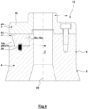
- the form-locking element 15 has a lateral surface 16 with a star-shaped cross-section or a toothing of any shape, a polygon or similar.
- the drive head 2 has a recess 17 extending in the direction of a rotation axis 39.
- this recess 17 has a truncated conical surface in the lower end area, which continues into a cylindrical bore.
- the Recess 17 serves to attach the drive head 2 to a drive shaft of the laboratory centrifuge, which is not described in detail here.
- An eccentric mass body 18a, 18b, 18c is arranged in each of the eccentric mass body receiving spaces 14a, 14b, 14c.
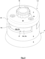
- the eccentric mass bodies 18 are each designed as circular ring segments 19a, 19b, 19c.
- the radially inner end face of the circular ring segments 19 is preferably designed in the shape of a cylinder segment.
- the end faces of the circular ring segments 19 in the circumferential direction are oriented radially to the axis of rotation 39.
- the lower and upper sides of the circular ring segments 19 are oriented parallel to one another with a surface normal that is oriented parallel to the axis of rotation 39.
- the outer surface 20 of the circular ring segments 19 is designed in the shape of a truncated cone segment and forms an eccentric mass body ramp surface 21 that is inclined relative to an axis of rotation 39 with a ramp surface angle 22 that is preferably 15° +/- 5°.
- Two guide projections 24, 25 each extend into the eccentric mass body receiving spaces 14, which for the embodiment shown are designed as guide bolts 26, 27 oriented parallel to the rotation axis 39.
- the guide bolts 26, 27 enter into radially oriented grooves or elongated holes on the underside of the eccentric mass body 18, the longitudinal axis of which is preferably oriented radially to the rotation axis 39.
- the engagement of the guide bolts 26, 27 in the grooves or elongated holes ensures that the eccentric mass body 18 is guided in such a way that the movement of the eccentric mass body takes place in the radial direction to the rotation axis 39.
- the counter-form-locking element 35 has an inner surface whose cross-section corresponds to the cross-section of the outer surface 16 of the form-locking element 15, so that the form-locking element 15 can be arranged in a precise and form-fitting manner for the transmission of a drive torque in the counter-form-locking element 35.
- the eccentric mass bodies 18 are in their starting position.
- the magnet 36 of the eccentric mass body 18 is arranged with the opposite pole adjacent to and aligned with the pole of the magnet 28, so that the starting position is secured via the magnetic force between the magnets 28, 36.
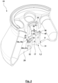
- the drive movement is transmitted to the drive head 2 via the shaft-hub connection between the drive shaft and the drive head 2, which in turn is transmitted to the rotor 23 via the positive locking between the positive locking element 15 and the counter-positive locking element 35.
- the centrifugal force acting on the eccentric mass bodies 18 overcomes the magnetic securing force, the eccentric mass bodies 18 slide radially outwards in the eccentric mass body receiving spaces 14 until the Eccentric mass body 18 with the eccentric mass body ramp surfaces 21 come into contact with the rotor ramp surfaces 33.
- the centrifugal forces acting in the contact surface thus generated are converted, as a result of the ramp surface angle 22, into an axial force which presses the base body 29 of the rotor 23 with the rotor cone surface 31 against the drive element cone surface 5.
- the interaction of the eccentric mass bodies 18 with the eccentric mass body ramp surfaces 21 with the rotor ramp surfaces 33 of the base body 29 of the rotor forms a coupling device 37, via which a reliable connection between the rotor 23 and the drive head is ensured as long as a sufficient centrifugal force is generated on the eccentric mass bodies 18 as a result of the rotation.
- Fig. 3 , 4 and 5 show the drive head 2 in a state of the coupling device 37 in which the eccentric mass bodies 18 are in the starting position.
- Fig. 6 to 9 an operating state of the coupling device 37 in which the eccentric mass bodies 18 are in the coupled position or securing position. If, after centrifugation has ended, it is desired to remove the rotor 23 from the drive head 2, the eccentric mass bodies 18 may well still be in the securing position.
- guidance can be ensured by precisely fitting cylindrical contact surfaces between the guide surfaces 6, 32. It is also possible that in these areas there is no guidance via contact surfaces, but rather there is a play. In this case, guidance can be provided by means of guide surfaces 42, 43, which are formed by the outer surface of the circular disk 10 and an inner surface of the rotor 23.
- the form-locking element 15 and the counter-form-locking element 35 are arranged in this axial order, with the form-locking element 15 being arranged furthest in the rotor 23.
- the form-locking element 15 being arranged furthest in the rotor 23.
- the arrangement of the form-locking element 15 and the counter-form-locking element 35 and/or the eccentric mass body ramp surface 21 and the rotor ramp surface 33 can also take place in a material area of the rotor 23 that has a smaller axial distance from the drive for rigid support and a reduced lever arm of any forces.
- this design enables more material to be made available in the area of the elements mentioned, which can result in improved strength.
- the functional surfaces with which the rotor 23 interacts with the drive head 2 were formed integrally from the base body 29.
- these functional surfaces are at least partially formed by an insert sleeve 38, which can be inserted into the base body 29 and screwed to it.
- the insert sleeve 38 forms both the rotor ramp surface 33 and the counter-form-locking element 35, while the rotor cone surface 31 is formed by the base body 29.
- the eccentric mass body ramp surfaces 21 are rounded in the region of the axial edges.
- the coupling device 37 can be released in particular without tools by applying removal forces to the rotor 23. It is possible that after operation of the When the rotor 23 comes to a standstill in the centrifuge, the magnets 28, 36 automatically move the eccentric mass bodies 18 back to the unlocked starting position. However, it is also possible that, alternatively or cumulatively, the removal forces manually applied by the user to the rotor 23 are converted via the angle of inclination of the eccentric mass body ramp surfaces 21 into a force that moves the eccentric mass bodies 18 back to the unlocked starting position.
- the eccentric mass bodies 18 are made of stainless steel, whereby it is possible that the base body 29 of the rotor 23 and/or the insert sleeve 38 is made of aluminum or stainless steel.
- the counter-form-locking element 35 can also be arranged axially on the outside of the rotor 23, whereby the form-locking element 15 is then arranged in the lower end region of the base body 4.
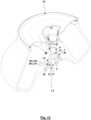
- Fig. 14 shows an embodiment in which a connection between the drive head 2 and the rotor 23 is not exclusively made and secured by the fact that the rotor 23 is clamped with the rotor cone surface 31 and the rotor ramp surface 33 between the eccentric mass body ramp surface 21 and the output element cone surface 5. Rather, an additional connection and securing is made here by the fact that the base body 29 of the rotor 23 has a groove or undercut 44.
- the eccentric mass body 18 has an outwardly oriented locking element 45.
- the locking element 45 is directly connected to the eccentric mass body ramp surface 21, wherein the locking element 45 is arranged in the end region of the eccentric mass body ramp surface 21 that has the smaller distance from the axis of rotation 39.
- the locking element 45 enters the groove or undercut 44, whereby a locked operating state is achieved.
- the locking element 45 and the groove or undercut 44 form a positive connection which blocks removal of the rotor 23 from the drive head 2 in a removal direction which corresponds to the direction of the axis of rotation 39.
- the contact surfaces 46, 47 of the eccentric mass body 18 and the groove or undercut 44 can have any shape.
- the contact surfaces 46, 47 can be designed as circular ring segment surfaces whose surface normal corresponds to the axis of rotation 39, or the contact surfaces 46, 47 can form any cone angle to the axis of rotation 39.
- Fig. 14 shows an embodiment in which the contact surface 47 of the groove or undercut 44 has a nose 48 which engages in a recess 49 of the contact surface 46.
- Unlocking can occur when, with the braking of the rotor 23, the force of the magnets 28, 36 on the eccentric mass bodies 18 becomes greater than the friction force component acting radially outward in the contact surfaces and the remaining centrifugal force acting on the eccentric mass bodies 18.
- unlocking can occur, for example, via a spring or a manually operated unlocking device.
- the eccentric mass bodies 18 each form both the eccentric mass body ramp surfaces 21 and the locking elements 45.
- first eccentric mass bodies it is also possible for first eccentric mass bodies to form the eccentric mass body ramp surfaces 21 while the locking elements 45 are formed by the second eccentric mass bodies.
Landscapes
- Centrifugal Separators (AREA)
Abstract
Die Erfindung betrifft einen Rotor (23), der über eine Zentrifugalkraft betätigte Kupplungseinrichtung (37) mit einen Antriebselement (1) verbunden ist. Die Kupplungseinrichtung (37) weist einen Exzentermassekörper (18) auf, der beweglich an dem Antriebselement (1) geführt ist. Des Weiteren weist die Kupplungseinrichtung (37) einen Rotorrücksprung (40) auf, hinter den der Exzentermassekörper (18) infolge der Zentrifugalkraft bewegt werden kann.The invention relates to a rotor (23) which is connected to a drive element (1) via a clutch device (37) actuated by centrifugal force. The clutch device (37) has an eccentric mass body (18) which is movably guided on the drive element (1). Furthermore, the clutch device (37) has a rotor recess (40) behind which the eccentric mass body (18) can be moved as a result of the centrifugal force.
Erfindungsgemäß ist der Exzentermassekörper (18) entlang einer Führungsbahn (41) an dem Antriebselement (1) geführt. Vorzugsweise verfügt der Exzentermassekörper (18) über eine Exzentermassekörper-Rampenfläche (21) und der Rotorrücksprung (40) weist eine Rotor-Rampenfläche (33) auf. Die Rampenflächen (21, 33) sind unter einem Rampenflächenwinkel gegenüber einer Drehachse (39) des Rotors (23) geneigt, der kleiner ist als 45°.

Description
Die Erfindung betrifft eine Zentrifuge, insbesondere eine Laborzentrifuge. Zentrifugen der hier vorliegenden Art finden Einsatz beispielsweise in der Biotechnologie, der pharmazeutischen Industrie, der Medizintechnik und der Umweltanalytik. Mittels einer derartigen Zentrifuge erfolgt ein Zentrifugieren eines Produkts, insbesondere eines Behälters oder Gefäßes mit darin angeordneter Probe oder Substanz, oder einer Vielzahl derartiger Produkte mit Drehzahlen, welche mehr als 3.000 U/min, bspw. mehr als 15.000 U/min, betragen können. Infolge der Zentrifugation sollen auf das Produkt wirkende Beschleunigungen erzeugt werden, welche bspw. mehr als 15.000 x g (insbesondere mehr als 16.000 x g, mehr als 20.000 x g bis hin zu mehr als 60.000 x g) betragen können. Durch die Zentrifugation soll ein von der Probe oder der Substanz gebildetes Stoffgemisch in Komponenten unterschiedlicher Dichte zerlegt werden. Je nach den chemischen und/oder physikalischen Eigenschaften des Stoffgemisches kann während der Zentrifugation ergänzend eine gezielte Steuerung der Druck- und/oder Temperaturverhältnisse erfolgen. Um lediglich einige Beispiele zu nennen, kann der Einsatz einer Laborzentrifuge im Zusammenhang mit einer Polymerase-Kettenreaktion (PCR), einer Bestimmung des Hematokrits, zytologischen Untersuchungen oder dem Zentrifugieren von Mikrotitern, Blutbeuteln, Erdölgefäßen oder Blutgefäßen u. ä. erfolgen. In der Zentrifuge ist mindestens ein Produkt in einem Rotor angeordnet oder das mindestens eine Produkt ist an einem Rotor gehalten. Der Rotor kann dabei bspw. als so genannter Festwinkelrotor oder Ausschwingrotor ausgebildet sein kann.The invention relates to a centrifuge, in particular a laboratory centrifuge. Centrifuges of the type in question are used, for example, in biotechnology, the pharmaceutical industry, medical technology and environmental analysis. A centrifuge of this type is used to centrifuge a product, in particular a container or vessel with a sample or substance arranged therein, or a large number of such products, at speeds that can be more than 3,000 rpm, for example more than 15,000 rpm. As a result of the centrifugation, accelerations acting on the product are to be generated, which can be, for example, more than 15,000 x g (in particular more than 16,000 x g, more than 20,000 x g up to more than 60,000 x g). The centrifugation is intended to break down a mixture of substances formed by the sample or substance into components of different densities. Depending on the chemical and/or physical properties of the mixture of substances, the pressure and/or temperature conditions can also be controlled during centrifugation. To name just a few examples, a laboratory centrifuge can be used in connection with a polymerase chain reaction (PCR), a determination of the hematocrit, cytological examinations or the centrifugation of microtiters, blood bags, petroleum containers or blood vessels, etc. In the centrifuge, at least one product is arranged in a rotor or the at least one product is held on a rotor. The rotor can be designed, for example, as a so-called fixed-angle rotor or swing-out rotor.
Des Weiteren betrifft die Erfindung einen Rotor für eine Zentrifuge sowie einen Antriebskopf für eine Zentrifuge.Furthermore, the invention relates to a rotor for a centrifuge and a drive head for a centrifuge.
Um den Rotor mit den Produkten in die für das Zentrifugieren erforderliche Rotation zu versetzen, wird ein Abtriebselement des Rotors über eine Kupplungseinrichtung mit einem üblicherweise von einer Antriebswelle ausgebildeten Antriebselement der Laborzentrifuge, welches von einem Motor angetrieben ist, gekuppelt. Hierbei dient die Kupplungseinrichtung einer axialen Sicherung des Abtriebselements auf dem Antriebselement und damit des Rotors auf der angetriebenen Antriebswelle des Motors. Möglich ist, dass die Kupplungseinrichtung auch der formschlüssigen Übertragung des Antriebsmoments von der Antriebswelle auf den Rotor dient. Ebenfalls möglich ist, dass die Übertragung des Antriebsmoments über einen Reibschluss von Kupplungsflächen erfolgt, wobei die Anpresskraft der Kupplungsflächen abhängig sein kann von einem Eigengewicht des Rotors und einer Kraftkomponente einer Kupplungskraft. An die Betriebssicherheit der Kupplungseinrichtung sind hohe Anforderungen zu stellen insbesondere infolge sich bei den hohen Drehzahlen ergebenden aerodynamischen Effekten, den großen Zentrifugalkräften, Kreiseleffekten bei einem sichtlichen Stoß auf die Laborzentrifuge und ähnlichem.In order to set the rotor with the products into the rotation required for centrifugation, an output element of the rotor is coupled via a coupling device to a drive element of the laboratory centrifuge, which is usually formed by a drive shaft and driven by a motor. The coupling device serves to axially secure the output element on the drive element and thus the rotor on the driven drive shaft of the motor. It is possible that the coupling device also serves to positively transfer the drive torque from the drive shaft to the rotor. It is also possible that the drive torque is transferred via a frictional connection of coupling surfaces, whereby the contact force of the coupling surfaces can be dependent on the rotor's own weight and a force component of a coupling force. High demands must be placed on the operational reliability of the coupling device, particularly due to the aerodynamic effects that arise at high speeds, the large centrifugal forces, gyroscopic effects in the event of a visible impact on the laboratory centrifuge and the like.
In einem bestimmungsgemäßen Laborbetrieb der Laborzentrifuge ist eine wiederholte Montage und Demontage des Rotors erforderlich, um mit demselben Rotor oder unterschiedlichen Rotoren sukzessive eine Vielzahl von Gefäßen mit zu zentrifugierenden Substanzen untersuchen zu können. Hierbei hat sich herausgestellt, dass angesichts des manuellen Betätigungsaufwands und des hiermit verbundenen Zeitbedarfs, aber auch hinsichtlich der Betriebssicherheit der Einsatz von manuell betätigten Kupplungseinrichtungen nachteilig sein kann. Aus diesem Grund finden zentrifugalkraftbetätigte Kupplungseinrichtungen Einsatz, bei welchen das Abtriebselement des Rotors lediglich auf das von dem Motor angetriebene Antriebselement der Laborzentrifuge aufgesetzt wird. Während anfänglich lediglich ein Reibschluss zwischen Antriebselement und Abtriebselement infolge des Eigengewichts des Rotors für die Kupplung zwischen Antriebselement und Abtriebselement sorgt, steigt mit zunehmender Drehzahl des Rotors zentrifugalkraftbedingt die Kupplungskraft der zentrifugalkraftbetätigten Kupplungseinrichtung. Je größer hierbei die Drehzahl ist umso größer ist automatisch die durch die Zentrifugalkraft erzeugte Kupplungskraft. Möglich ist auch, dass zusätzlich zu einer derartigen zentrifugalkraftbetätigten Kupplungseinrichtung auch eine manuell betätigte Kupplungseinrichtung eingesetzt ist.When the laboratory centrifuge is used as intended in a laboratory, the rotor must be repeatedly assembled and disassembled in order to be able to successively examine a large number of vessels with substances to be centrifuged using the same rotor or different rotors. It has been found that the use of manually operated coupling devices can be disadvantageous in view of the manual operation effort and the associated time required, but also in terms of operational safety. For this reason, centrifugal force-operated coupling devices are used in which the output element of the rotor is simply placed on the drive element of the laboratory centrifuge driven by the motor. While initially only a frictional connection between the drive element and output element due to the rotor's own weight ensures the coupling between the drive element and output element, the coupling force of the centrifugal force-operated coupling device increases as the speed of the rotor increases due to centrifugal force. The higher the speed, the greater the clutch force generated by the centrifugal force. It is also possible that a manually operated clutch device is used in addition to such a centrifugal force-operated clutch device.
Bekannt sind Ausführungsformen, bei denen ein Exzentermassekörper, der mit der Zentrifugalkraft beaufschlagt wird und die Kupplungskraft herbeiführt, an dem Rotor gelagert ist. Der Exzentermassekörper führt dann eine Verriegelung mit einer Verriegelungsnut einer Antriebswelle herbei. Problematisch hierbei ist, dass die Zentrifugalkraft radial nach außen wirkt, während eine Verriegelung radial nach innen mit der Verriegelungsnut der Antriebswelle erforderlich ist. Aus diesem Grund finden Verriegelungshebel Einsatz, die um eine tangential zur Umfangsrichtung orientierte Schwenkachse verschwenkbar sind. Der Schwerpunkt des Verriegelungshebels liegt dabei radial außenliegend von der Schwenkachse, sodass eine Verschwenkung infolge der Zentrifugalkraft zur Folge hat, dass das radial innenliegende Hebelteil des Verriegelungshebels radial nach innen beaufschlagt wird. Kupplungseinrichtungen, bei denen ein verschwenkbarer Verriegelungshebel an dem Rotor gehalten ist, sind beispielsweise aus den Druckschriften
Auch gemäß
Aus
Weiterer Stand der Technik ist insbesondere aus
Der Erfindung liegt die Aufgabe zugrunde, eine Zentrifuge mit einer alternativen zentrifugalkraftbetätigten Kupplungseinrichtung für ein drehfeste und axial gesicherte Kupplung eines Rotors mit einem Antriebselement einer Antriebseinheit vorzuschlagen, die insbesondere hinsichtlich
- der Sicherheit der Kupplungseinrichtung im Betrieb der Zentrifuge und/oder
- einer einfachen, aber dennoch zuverlässigen Bedienung und/oder
- der Komplexität erforderlichen Bauelemente und/oder
- der Kosten und/oder
- der Robustheit und/oder
- einer Bedienbarkeit ohne manuelle Betätigungselemente
- the safety of the coupling device during operation of the centrifuge and/or
- a simple, yet reliable operation and/or
- the complexity required components and/or
- the costs and/or
- the robustness and/or
- operability without manual controls
Die Aufgabe der Erfindung wird erfindungsgemäß mit den Merkmalen der unabhängigen Patentansprüche gelöst. Weitere bevorzugte erfindungsgemäße Ausgestaltungen sind den abhängigen Patentansprüchen zu entnehmen.The object of the invention is achieved according to the invention with the features of the independent patent claims. Further preferred embodiments according to the invention can be found in the dependent patent claims.
Die Erfindung schlägt eine Zentrifuge, insbesondere eine Laborzentrifuge, vor, bei der ein Rotor, insbesondere ein Festwinkelrotor, über eine zentrifugalkraftbetätigte Kupplungseinrichtung mit einem Antriebselement verbunden ist. Bei der erfindungsgemäßen Kupplungseinrichtung ist der Exzentermassekörper nicht beweglich an dem Rotor geführt. Vielmehr ist der Exzentermassekörper der Kupplungseinrichtung beweglich an dem Antriebselement geführt. Der Rotor verfügt vorzugsweise über einen Rotorrücksprung. Infolge der Zentrifugalkraft kann der Exzentermassekörper hinter den Rotorrücksprung bewegt werden, womit die Kupplungswirkung herbeigeführt werden kann. Alternativ oder kumulativ möglich ist, dass der Exzentermassekörper (insbesondere zur Herbeiführung der Kupplungswirkung und/oder einer axialen Anpresskraft) durch die Zentrifugalkraft gegen eine Rampenfläche, insbesondere eine Rotorrücksprung-Rampenfläche oder Rotor-Rampenfläche, bewegt werden kann.The invention proposes a centrifuge, in particular a laboratory centrifuge, in which a rotor, in particular a fixed-angle rotor, is connected to a drive element via a centrifugal force-operated coupling device. In the coupling device according to the invention, the eccentric mass body is not movably guided on the rotor. Rather, the eccentric mass body of the coupling device is movably guided on the drive element. The rotor preferably has a rotor recess. As a result of the centrifugal force, the eccentric mass body can be moved behind the rotor recess, whereby the coupling effect can be brought about. Alternatively or cumulatively, it is possible for the eccentric mass body (in particular to bring about the coupling effect and/or an axial contact force) to be moved by the centrifugal force against a ramp surface, in particular a rotor recess ramp surface or rotor ramp surface.
Erfindungsgemäß wird vorgeschlagen, dass der Exzentermassekörper nicht verschwenkbar um eine Schwenkachse gelagert ist, sondern entlang einer Führungsbahn an dem Antriebselement geführt ist. Hierbei kann die Führungsbahn eine Führung entlang eines kurvenförmigen Freiheitsgrades vorgeben, wobei zumindest eine Komponente der Führungsbahn in radialer Richtung orientiert ist. Mittels der Zentrifugalkraft kann somit der Exzentermassekörper entlang der Führungsbahn bewegt werden. Vorzugsweise verfügt der Exzentermassekörper gegenüber dem Antriebselement über einen translatorischen Freiheitsgrad, der in radialer Richtung orientiert sein kann oder unter einem festen spitzen Winkel gegenüber der radialen Richtung orientiert sein kann.According to the invention, it is proposed that the eccentric mass body is not mounted so as to be pivotable about a pivot axis, but is guided along a guide track on the drive element. In this case, the guide track can provide guidance along a curved degree of freedom, with at least one component of the guide track being oriented in the radial direction. The eccentric mass body can thus be moved along the guide track by means of the centrifugal force. The eccentric mass body preferably has a translational degree of freedom relative to the drive element, which is oriented in the radial direction. or can be oriented at a fixed acute angle to the radial direction.
Die erfindungsgemäße Ausgestaltung beruht insbesondere auf der Erkenntnis, dass gemäß dem Stand der Technik bekannte, an dem Antriebselement gelagerte Verriegelungshebel einen großen Bauraum erfordern und hinsichtlich der Ausnutzung der Masse nicht optimal sind, da beidseits einer Schwenkachse angeordnete Verriegelungshebelteile entgegengesetzte Schwenkmomente erzeugen, sodass für die Verriegelungswirkung lediglich eine Differenz der Schwenkmomente genutzt werden kann. Hinzu kommt, dass die drehbare Lagerung einer Verriegelungshebels eine Lagerung mittels eines Gleit- oder Wälzlagers erfordert, die u. U. hohe Anforderungen an die Fertigung stellt, zusätzliche Bauelemente wie Wälzkörper oder Gleithülsen und geringere Fertigungstoleranzen im Bereich der Lagerflächen erfordert und verschleißanfällig ist. Hingegen kann im Rahmen der Erfindung im Extremfall ein klotzartiger Exzentermassekörper verwendet werden, der ausschließlich über flächige Gleitkontakte mit einer Führungsbahn geführt ist. Ein derartiger Exzentermassekörper kann einfach und kostengünstig hergestellt werden und ist auch bei dauerhaftem Betrieb bei hohen Drehzahlen einem geringen Verschleiß ausgesetzt. Über die Kontaktfläche des Exzentermassekörpers mit einer Führungsbahn können die Flächenpressungen klein gehalten werden und damit die mechanischen Beanspruchungen konstruktiv vorgegeben und reduziert werden. Im Vergleich zu dem zuvor genannten Verriegelungshebel kann des Weiteren die gesamte Masse des Exzentermassekörpers für die Erzeugung der Zentrifugalkraft und damit für die Kupplungskraft genutzt werden.The design according to the invention is based in particular on the knowledge that locking levers mounted on the drive element, as known from the prior art, require a large installation space and are not optimal in terms of the utilization of the mass, since locking lever parts arranged on both sides of a pivot axis generate opposing pivoting moments, so that only a difference in the pivoting moments can be used for the locking effect. In addition, the rotatable mounting of a locking lever requires a bearing by means of a sliding or rolling bearing, which may place high demands on production, requires additional components such as rolling elements or sliding sleeves and lower manufacturing tolerances in the area of the bearing surfaces and is susceptible to wear. In contrast, within the scope of the invention, in extreme cases a block-like eccentric mass body can be used which is guided exclusively via flat sliding contacts with a guide track. Such an eccentric mass body can be manufactured simply and inexpensively and is subject to little wear even during continuous operation at high speeds. The contact surface of the eccentric mass body with a guide track allows the surface pressures to be kept low, thus specifying and reducing the mechanical stresses in the design. In comparison to the locking lever mentioned above, the entire mass of the eccentric mass body can also be used to generate the centrifugal force and thus the coupling force.
Möglich ist, dass der Exzentermassekörper nach der Bewegung hinter den Rotorrücksprung infolge der Zentrifugalkraft eine formschlüssige Sicherung oder Verriegelung gewährleistet. Für einen Vorschlag der Erfindung weist der Exzentermassekörper eine Exzentermassekörper-Rampenfläche auf, während der Rotor oder ein Rotorrücksprung eine Rotor-Rampenfläche aufweist (im Folgenden auch gemeinsamen "Rampenfläche"). Die Rampenflächen sind in einem Halblängsschnitt hinsichtlich der Drehachse des Rotors unter einem Rampenflächenwinkel gegenüber der Drehachse des Rotors geneigt, der kleiner ist als 45° (insbesondere kleiner ist als 30° oder kleiner ist 25° oder kleiner ist 20°). Dieser Ausgestaltung der Erfindung liegt die Erkenntnis zugrunde, dass für aus dem Stand der Technik bekannten Zentrifugen die Lösung des Verriegelungshebels nach Beendigung des Betriebs der Zentrifuge separate Maßnahmen wie das Betätigen eine Löseknopfes erfordert oder Verriegelungshebel über einer Feder beaufschlagt sein müssen, die bei Entfall der Zentrifugationswirkung den Verriegelungshebel wieder in die Ausgangsstellung bewegt, in der der Rotor von dem Antriebselement entnommen werden kann. Wird aber der zuvor gemäß der Erfindung vorgeschlagene kleine Rampenflächenwinkel gewählt, kann eine Rückbewegung des Exzentermassekörpers hervorgerufen werden allein unter Aufbringung von Entnahmekräften auf den Rotor. Der Grund hierfür ist, dass die an der Rampenfläche wirkende Entnahmekraft über den Rampenflächenwinkel umgewandelt wird in eine auf den Exzentermassekörper wirkende Rückstellkraft, die eine Rückstellbewegung in die Ausgangsstellung, die der gelösten Kupplungseinrichtung entspricht, unterstützt oder sogar alleine hervorruft. Vorzugsweise ist dabei der Rampenflächenwinkel derart gewählt, dass keine Selbsthemmung im Bereich des Kontakts der Rampenflächen auftritt.It is possible that the eccentric mass body ensures a positive locking or locking after the movement behind the rotor recess as a result of the centrifugal force. For one proposal of the invention, the eccentric mass body has an eccentric mass body ramp surface, while the rotor or a rotor recess has a rotor ramp surface (hereinafter also referred to as the common "ramp surface"). The ramp surfaces are inclined in a semi-longitudinal section with respect to the axis of rotation of the rotor at a ramp surface angle with respect to the axis of rotation of the rotor that is less than 45° (in particular less than 30° or less than 25° or less than 20°). This embodiment of the invention is based on the knowledge that for centrifuges known from the prior art, the release of the locking lever after the centrifuge has finished operating requires separate measures such as pressing a release button or locking levers must be actuated by a spring that returns the locking lever to the Starting position in which the rotor can be removed from the drive element. However, if the small ramp surface angle previously proposed according to the invention is selected, a return movement of the eccentric mass body can be caused solely by applying removal forces to the rotor. The reason for this is that the removal force acting on the ramp surface is converted via the ramp surface angle into a restoring force acting on the eccentric mass body, which supports or even alone causes a return movement to the starting position, which corresponds to the released coupling device. The ramp surface angle is preferably selected such that no self-locking occurs in the area of contact of the ramp surfaces.
Im Rahmen der Erfindung kann das Antriebselement beliebig ausgebildet sein. So ist durchaus möglich, dass das Antriebselement unmittelbar von der Antriebswelle des Antriebsmotors ausgebildet ist. Für einen besonderen Vorschlag der Erfindung ist das Antriebselement ein (ein- oder mehrteiliger) Antriebskopf, der drehfest an der Antriebswelle des Antriebsmotors gehalten ist. Möglich ist beispielsweise, dass der Antriebskopf über eine an sich bekannte, ein Antriebsmoment übertragende Welle-Nabe-Verbindung mit der Antriebswelle verbunden ist, wobei eine Sicherung über eine mit der Stirnseite der Antriebswelle verschraubte Befestigungsschraube erfolgen kann.Within the scope of the invention, the drive element can be designed in any way. It is certainly possible for the drive element to be formed directly from the drive shaft of the drive motor. For a particular proposal of the invention, the drive element is a (single or multi-part) drive head that is held in a rotationally fixed manner on the drive shaft of the drive motor. It is possible, for example, for the drive head to be connected to the drive shaft via a shaft-hub connection known per se that transmits a drive torque, whereby securing can be achieved via a fastening screw screwed to the front of the drive shaft.
Für das Halten und Führen des Exzentermassekörper an dem Antriebselement gibt es im Rahmen der Erfindung vielfältige Möglichkeiten, solange eine Führung entlang einer gradlinigen oder kurvenförmigen Führungsbahn erfolgt. Eine besonders einfache Führung des Exzentermassekörpers kann darin bestehen, dass die Führung mittels eines Eingriffs eines Führungsvorsprungs (insbesondere eines Bolzens oder Stiftes) in eine Nut oder ein Langloch gewährleistet wird. So kann beispielsweise der Exzentermassekörper die Nut oder das Langloch aufweisen, während das Antriebselement dann den Führungsvorsprung, Bolzen oder Stift aufweist (wobei aber auch eine umgekehrte Anordnung des Langloches oder der Nut einerseits und des Führungsvorsprungs andererseits möglich ist).Within the scope of the invention, there are many different ways of holding and guiding the eccentric mass body on the drive element, as long as it is guided along a straight or curved guide path. A particularly simple way of guiding the eccentric mass body can be to ensure that the guide is ensured by means of an engagement of a guide projection (in particular a bolt or pin) in a groove or an elongated hole. For example, the eccentric mass body can have the groove or the elongated hole, while the drive element then has the guide projection, bolt or pin (although an inverted arrangement of the elongated hole or groove on the one hand and the guide projection on the other is also possible).
Im Rahmen der Erfindung kann eine beliebige Anzahl von Exzentermassekörpern Einsatz finden, wobei die Exzentermassekörper gleiche oder unterschiedliche Geometrien aufweisen können und bei gleichen oder unterschiedlichen Radien angeordnet sein können. Vorzugsweise sind mehrere Exzentermassekörper gleichmäßig in Umfangsrichtung an dem Antriebselement angeordnet und geführt. Eine besonders kompakte aber effiziente Ausgestaltung der Zentrifuge ergibt sich, wenn über den Umfang gleichmäßig verteilt genau drei Exzentermassekörper an dem Antriebselement geführt sind. Die drei Exzentermassekörper gewährleisten eine stabile Abstützung zwischen dem Rotor und dem Antriebselement in die erforderlichen Richtungen. Andererseits können die drei in Umfangsrichtung verteilten Exzentermassekörper eine verhältnismäßig große Masse aufweisen, womit eine hohe Sicherungswirkung herbeigeführt werden kann.Within the scope of the invention, any number of eccentric mass bodies can be used, whereby the eccentric mass bodies can have the same or different geometries and can be arranged at the same or different radii. Preferably, several eccentric mass bodies are arranged and guided evenly in the circumferential direction on the drive element. A particularly compact but efficient design of the centrifuge is achieved when exactly three eccentric mass bodies are guided on the drive element, evenly distributed over the circumference. The three eccentric mass bodies ensure stable support between the rotor and the drive element in the required directions. On the other hand, the three eccentric mass bodies distributed in the circumferential direction can have a relatively large mass, which can bring about a high securing effect.
Im Rahmen der Erfindung ist durchaus möglich, dass eine Übertragung des Antriebsmomentes zwischen dem Antriebselement und dem Rotor über eine reibschlüssige Verbindung erfolgen kann, wobei die reibschlüssige Verbindung vorzugsweise im Bereich von aneinander anliegenden Querflächen, Rampenflächen oder Konusflächen herbeigeführt wird. Hierbei kann die die Reibung hervorrufende Anpresskraft durch die Gewichtskraft des Rotors und/oder zumindest eine Komponente der Zentrifugalkraft oder Kupplungskraft hervorgerufen werden. Für einen Vorschlag der Erfindung weist das Antriebselement aber zusätzlich ein Formschlusselement auf. Das Formschlusselement des Antriebselements tritt dann mit einem Gegen-Formschlusselement des Rotors zur formschlüssigen Übertragung des Antriebsmomentes in Wechselwirkung. Für die Ausgestaltung des Formschlusselements und des Gegen-Formschlusselements gibt es vielfältige Möglichkeiten, wobei auch die aus dem Stand der Technik bekannten Möglichkeiten im Rahmen der Erfindung genutzt werden können. Vorzugsweise verfügen das Formschlusselement und das Gegen-Formschlusselement über einen unrunden, das Antriebsmoment übertragenden Querschnitt. So können beispielsweise das Formschlusselement und das Gegen-Formschlusselement als eine Art Verzahnung mit beliebiger Zahngeometrie oder als runder Querschnitt mit überlagerter Wellenkontur ausgebildet sein. Vorzugsweise bilden das Formschlusselement und das Gegen-Formschlusselement Einführhilfen oder -schrägen aus, die das Aufstecken des Rotors auf das Antriebselement nicht nur dann ermöglichen, wenn der Rotor in der exakten Drehwinkelstellung um die Rotationsachse an das Antriebselement angenähert wird.Within the scope of the invention, it is entirely possible for the drive torque to be transmitted between the drive element and the rotor via a frictional connection, with the frictional connection preferably being brought about in the region of adjacent transverse surfaces, ramp surfaces or conical surfaces. The contact force causing the friction can be caused by the weight of the rotor and/or at least one component of the centrifugal force or coupling force. For one proposal of the invention, however, the drive element also has a positive locking element. The positive locking element of the drive element then interacts with a counter-positive locking element of the rotor for the positive transmission of the drive torque. There are many possibilities for the design of the positive locking element and the counter-positive locking element, whereby the possibilities known from the prior art can also be used within the scope of the invention. The positive locking element and the counter-positive locking element preferably have a non-circular cross-section that transmits the drive torque. For example, the form-locking element and the counter-form-locking element can be designed as a type of toothing with any tooth geometry or as a round cross-section with a superimposed wave contour. The form-locking element and the counter-form-locking element preferably form insertion aids or bevels that enable the rotor to be attached to the drive element not only when the rotor is approached to the drive element in the exact angle of rotation position around the axis of rotation.
Durchaus erwünscht sein kann, dass eine Sicherung des Exzentermassekörpers in der Ausgangsstellung, die der gelösten Kupplungseinrichtung entspricht, erfolgt. Eine derartige Sicherung in der Ausgangsstellung kann vorteilhaft sein um zu vermeiden, dass die Exzentermassekörper unerwünscht für einen entnommenen Rotor die Ausgangstellung verlassen, womit dann das Aufstecken eines neuen Rotors unmöglich oder erschwert sein kann. Für die Sicherung des Exzentermassekörpers in der Ausgangstellung können beliebige Rasteinrichtungen oder eine Feder (vgl. den eingangs genannten Stand der Technik) verwendet werden, um lediglich einige die Erfindung nicht beschränkende Beispiele zu nennen. Für einen Vorschlag der Erfindung ist der Exzentermassekörper über einen Magneten in einer Ausgangsstellung gesichert. So können bspw. das Antriebselement und der Exzentermassekörper (Permanent-) Magnete aufweisen, deren aneinander anziehende Pole in der Ausgangsstellung fluchtend und eng benachbart angeordnet sind, während sich deren Abstand bei dem Verlassen der Ausgansstellung vergrößert. Neben der Sicherungswirkung in der Ausgangstellung kann ein Magnet auch einen Beitrag dazu leisten, dass der Exzentermassekörper nach der Beendigung der Zentrifugation in die Ausgangsstellung zurückkehrt. Die Auslegung des Magneten und der durch den Magneten herbeigeführten Sicherungswirkung erfolgt dabei so, dass die Sicherung automatisch gelöst wird, wenn eine Verdrehung des Antriebselements mit dem Exzentermassekörper mit einem Schwellwert der Drehzahl erfolgt, bis zu welcher die Sicherungswirkung gewünscht ist. In diesem Fall ruft die Drehzahl eine auf den Exzentermassekörper wirkende Zentrifugalkraft hervor, die die magnetische Sicherungskraft überwinden kann.It may be desirable for the eccentric mass body to be secured in the starting position, which corresponds to the released coupling device. Such a securing in the starting position can be advantageous in order to avoid the eccentric mass body leaving the starting position for a removed rotor, which can then make it impossible or difficult to attach a new rotor. Any locking device or a spring (cf. the prior art mentioned at the beginning) can be used to secure the eccentric mass body in the starting position, to name just a few non-limiting examples. For a proposal of the According to the invention, the eccentric mass body is secured in a starting position by a magnet. For example, the drive element and the eccentric mass body can have (permanent) magnets whose mutually attractive poles are aligned and arranged closely next to each other in the starting position, while their distance increases when leaving the starting position. In addition to the securing effect in the starting position, a magnet can also help ensure that the eccentric mass body returns to the starting position after centrifugation has ended. The magnet and the securing effect brought about by the magnet are designed in such a way that the securing is automatically released when the drive element with the eccentric mass body is rotated at a threshold speed up to which the securing effect is desired. In this case, the speed causes a centrifugal force acting on the eccentric mass body, which can overcome the magnetic securing force.
Für einen weiteren Vorschlag der Erfindung weist das Antriebselement eine Antriebselement-Konusfläche auf. Der Rotor weist eine Rotor-Konusfläche auf. Die Antriebselement-Konusfläche und die Rotor-Konusfläche sind entgegengesetzt zu der Exzentermassekörper-Rampenfläche und der Rotor-Rampenfläche geneigt, was zur Folge hat, dass der Rotor mit der Rotor-Konusfläche und Rotor-Rampenfläche "gefangen ist" zwischen der Antriebselement-Konusfläche und der Exzentermassekörper-Rampenfläche. Hierbei können die entgegengesetzten Winkel einerseits der Antriebselement-Konusfläche und der Rotor-Konusfläche und andererseits der Exzentermassekörper-Rampenfläche und der Rotor-Rampenfläche gleich groß oder unterschiedlich groß sein.For a further proposal of the invention, the drive element has a drive element conical surface. The rotor has a rotor conical surface. The drive element conical surface and the rotor conical surface are inclined in the opposite direction to the eccentric mass body ramp surface and the rotor ramp surface, which means that the rotor with the rotor conical surface and rotor ramp surface is "caught" between the drive element conical surface and the eccentric mass body ramp surface. The opposite angles of the drive element conical surface and the rotor conical surface on the one hand and the eccentric mass body ramp surface and the rotor ramp surface on the other hand can be the same or different.
Alternativ möglich ist, dass die Antriebselement-Konusfläche und die Exzentermassekörper-Rampenfläche zwischen der Rotor-Konusfläche und der Rotor-Rampenfläche "gefangen sind". Für diese Ausgestaltung erzeugen die Zentrifugalkraft und die hierdurch hervorgerufene Kupplungskraft eine Anpresskraft an die genannten Konusflächen und Rampenflächen, sodass ein axiales Verspannen des Rotors an dem Antriebselement erfolgt.Alternatively, it is possible for the drive element cone surface and the eccentric mass body ramp surface to be "caught" between the rotor cone surface and the rotor ramp surface. For this design, the centrifugal force and the coupling force caused by this generate a contact force on the said cone surfaces and ramp surfaces, so that the rotor is axially clamped to the drive element.
Während durchaus auch eine andere Anordnung möglich ist, schlägt die Erfindung für einen weiteren Vorschlag vor, dass die Antriebselement-Konusfläche und die Rotor-Konusfläche auf der dem Antrieb abgewandten Seite (dass heißt für eine vertikale Anordnung der Rotorachse mit unten liegendem Antrieb oberhalb) von der Exzentermassekörper-Rampenfläche und der Rotor-Rampenfläche angeordnet sind. Dies ermöglicht eine besonders kompakte, zuverlässige und beständige Ausgestaltung der gebildeten Welle-Nabe-Verbindung zum Halten des Rotors und für die Kupplungseinrichtung.While another arrangement is also possible, the invention proposes for a further proposal that the drive element cone surface and the rotor cone surface are arranged on the side facing away from the drive (i.e. for a vertical arrangement of the rotor axis with the drive below, above) of the eccentric mass body ramp surface and the rotor ramp surface. This enables a particularly compact, reliable and Durable design of the shaft-hub connection formed for holding the rotor and for the coupling device.
Auch für die Anordnung des Formschlusselements und des Gegen-Formschlusselements in axialer Richtung und relativ zu den Konusflächen und Rampenflächen gibt es im Rahmen der Erfindung vielfältige Möglichkeiten. Für einen Vorschlag der Erfindung sind das Formschlusselement und das Gegenformschlusselement zwischen einerseits Antriebselement-Konusfläche und der Rotor-Konusfläche und andererseits der Exzentermassekörper-Rampenfläche und der Rotor-Rampenfläche angeordnet. Diese Ausgestaltung verlagert vorzugsweise das Formschlusselement und das Gegen-Formschlusselement von dem innenliegend von dem Rotor angeordneten Endbereich des Antriebselements weg, was zur Folge haben kann, dass eine besonders steife und zuverlässige Übertragung des Antriebsmomentes zwischen dem Formschlusselement und dem Gegen-Formschlusselement möglich ist und unter Umständen auch mehr Material im Bereich des Antriebselements für die Ausgestaltung und Abstützung des Formschlusselementes vorhanden ist.There are also a variety of options within the scope of the invention for the arrangement of the form-locking element and the counter-form-locking element in the axial direction and relative to the conical surfaces and ramp surfaces. For one proposal of the invention, the form-locking element and the counter-form-locking element are arranged between the drive element conical surface and the rotor conical surface on the one hand and the eccentric mass body ramp surface and the rotor ramp surface on the other. This design preferably shifts the form-locking element and the counter-form-locking element away from the end region of the drive element arranged on the inside of the rotor, which can result in a particularly rigid and reliable transmission of the drive torque between the form-locking element and the counter-form-locking element being possible and, under certain circumstances, more material being available in the area of the drive element for the design and support of the form-locking element.
Der Rotor kann auf beliebige Weise die erläuterten Funktionsflächen für die Wechselwirkung mit dem Antriebselement ausbilden, wobei der Rotor hierzu eine beliebige Anzahl von Bauelementen aufweisen kann. Gemäß einem Vorschlag der Erfindung weist der Rotor eine (ein- oder mehrteilige) Einsatzhülse auf. In diese Einsatzhülse kann dann das Antriebselement eintreten und zumindest ein Teil der erforderlichen Wechselwirkungen herbeiführen und die Funktionsflächen bereitstellen. Zu diesem Zweck kann die Einsatzhülse die Rotor-Rampenfläche und/oder das Gegen-Formschlusselement ausbilden. Optional möglich ist, dass die Einsatzhülse dann auch die Rotor-Konusfläche ausbildet.The rotor can form the functional surfaces explained for interaction with the drive element in any way, whereby the rotor can have any number of components for this purpose. According to one proposal of the invention, the rotor has a (single-part or multi-part) insert sleeve. The drive element can then enter this insert sleeve and bring about at least some of the required interactions and provide the functional surfaces. For this purpose, the insert sleeve can form the rotor ramp surface and/or the counter-form-locking element. It is optionally possible for the insert sleeve to then also form the rotor cone surface.
Auch für die Ausgestaltung des Antriebselements, insbesondere des Antriebskopfes, gibt es vielfältige Möglichkeiten, wobei vorzugsweise das Antriebselement mehrteilig ausgebildet ist. Für einen Vorschlag der Erfindung weist das Antriebselement einen Grundkörper auf. Vorzugsweise bildet dieser Grundkörper dann die Antriebselement-Konusfläche aus. Des Weiteren verfügt das Antriebselement über einen Abdeckkörper, der mit dem Grundkörper verbunden ist. Zwischen dem Grundkörper und dem Abdeckkörper ist dann ein Exzentermassekörper-Aufnahmeraum gebildet. In dem Exzentermassekörper-Aufnahmeraum kann dann der Exzentermassekörper beweglich angeordnet sein. In dem Exzentermassekörper-Aufnahmeraum ist dann der Exzentermassekörper auch entlang der Führungsbahn geführt. Vorzugsweise erfolgt diese Führung durch eine Kontaktfläche des Exzentermassekörpers mit dem Grundkörper und/oder dem Abdeckkörper. Eine derartige Kontaktfläche kann eine Flächennormale aufweisen, die parallel zur Drehachse des Rotors orientiert ist. Das Weiteren möglich ist, dass der Grundkörper und/oder der Abdeckkörper radial orientierte Rippen aufweisen, über welche (unter Umständen zusätzlich zu dem Führungsvorsprung, der Nut oder dem Langloch) eine Führung des Exzentermassekörpers erfolgen kann, wobei dann beispielsweise eine Flächennormale einer Kontaktfläche des Exzentermassekörpers mit einer derartigen Rippe tangential zur Umfangsrichtung orientiert sein kann.There are also many different options for the design of the drive element, in particular the drive head, whereby the drive element is preferably made up of several parts. According to one proposal of the invention, the drive element has a base body. This base body preferably then forms the drive element conical surface. The drive element also has a cover body which is connected to the base body. An eccentric mass body receiving space is then formed between the base body and the cover body. The eccentric mass body can then be movably arranged in the eccentric mass body receiving space. The eccentric mass body is then also guided along the guide track in the eccentric mass body receiving space. This guidance preferably takes place through a contact surface of the eccentric mass body with the base body and/or the cover body. Such a contact surface can have a surface normal that is oriented parallel to the axis of rotation of the rotor. It is also possible for the base body and/or the cover body to have radially oriented ribs, via which the eccentric mass body can be guided (possibly in addition to the guide projection, the groove or the elongated hole), in which case, for example, a surface normal of a contact surface of the eccentric mass body with such a rib can be oriented tangentially to the circumferential direction.
Für die Form des (ein- oder mehrteiligen) Exzentermassekörpers gibt es vielfältige Möglichkeiten. Für einen Vorschlag der Erfindung ist der Exzentermassekörper (zumindest in grober Näherung) als (einstückiges oder mehrstückiges) Kreisringsegment ausgebildet. Eine radial außenliegende Stirnseite des Kreisringsegments kann dann die Exzentermassekörper-Rampenfläche ausbilden. Möglich ist beispielsweise, dass die Mittelpunkte der Innenfläche und der Außenfläche des Kreisringsegments in radialer Richtung versetzt zueinander angeordnet sind. So ist bspw. möglich, dass die Mittelpunkte um den Verschiebeweg des Exzentermassekörpers versetzt zueinander angeordnet sind, woraus sich eine besonders kompakte Ausführungsform ergeben kann.There are many different options for the shape of the (single or multi-part) eccentric mass body. For one proposal of the invention, the eccentric mass body is designed (at least roughly) as a (single or multi-part) circular ring segment. A radially outer end face of the circular ring segment can then form the eccentric mass body ramp surface. It is possible, for example, that the centers of the inner surface and the outer surface of the circular ring segment are arranged offset from one another in the radial direction. For example, it is possible that the centers are arranged offset from one another by the displacement path of the eccentric mass body, which can result in a particularly compact embodiment.
Finden mehrere als Kreisringsegment ausgebildete Exzentermassekörper Einsatz, die dieselbe Form und dieselben Radien aufweisen, ist die Summe der Erstreckungen der Kreisringsegmente vorzugsweise größer als 300°, größer als 320° oder größer als 330°, womit eine sehr kompakte Ausgestaltung trotz hoher Masse der Exzentermassekörper gewährleistet werden kann.If several eccentric mass bodies designed as circular ring segments are used, which have the same shape and the same radii, the sum of the extensions of the circular ring segments is preferably greater than 300°, greater than 320° or greater than 330°, which can ensure a very compact design despite the high mass of the eccentric mass bodies.
Zusätzlich zu den erläuterten Verbindungs- und Sicherungsmaßnahmen für die Befestigung des Rotors an dem Antriebskopf können beliebige weitere Verbindungs- und/oder Sicherungsmaßnahmen Einsatz finden. Für einen Vorschlag der Erfindung weist der Exzentermassekörper ein Verriegelungselement auf, welches mit einer Nut oder Hinterschneidung des Rotors in Wechselwirkung tritt. Mittels der Wechselwirkung, insbesondere eines Eingriffs des Verriegelungselements in die Nut oder hinter die Hinterschneidung, kann eine formschlüssige Sicherung gewährleistet werden. Eine Entriegelung kann beispielsweise bei Stillstand infolge der Magnetkraft der Magneten erfolgen, mittels eines manuell betätigten Entriegelungsmechanismus erfolgen oder über eine Feder erfolgen.In addition to the connection and securing measures explained for fastening the rotor to the drive head, any other connection and/or securing measures can be used. For one proposal of the invention, the eccentric mass body has a locking element which interacts with a groove or undercut of the rotor. By means of the interaction, in particular an engagement of the locking element in the groove or behind the undercut, a positive locking can be ensured. Unlocking can take place, for example, when the vehicle is at a standstill as a result of the magnetic force of the magnets, by means of a manually operated unlocking mechanism or by means of a spring.
Eine weitere Lösung der der Erfindung zugrunde liegenden Aufgabe stellt ein Rotor dar, der für eine Zentrifuge bestimmt ist, wie diese zuvor erläutert worden ist, und entsprechend gestaltet ist.
- Um lediglich einige Beispiele zu nennen, kann der Rotor einen Rotorrücksprung aufweisen, hinter den der Exzentermassekörper infolge der Zentrifugalkraft bewegt werden kann.
- Der Rotorrücksprung kann eine Rotor-Rampenfläche aufweisen, die in einem Halblängsschnitt unter einem Rampenflächenwinkel gegenüber einer Drehachse des Rotors geneigt ist, der kleiner
ist als 45° (insbesondere kleinerist 30° oder kleiner ist 25° oderkleiner ist als 20°). - Der Rotor kann ein Gegen-Formschlusselement aufweisen, welches mit dem Formschlusselement des Antriebselements zur formschlüssigen Übertragung des Antriebsmomentes in Wechselwirkung tritt.
- Der Rotor kann eine Rotor-Konusfläche aufweisen, wobei die Rotor-Konusfläche entgegengesetzt zu der Rotor-Rampenfläche geneigt sein kann.
- Möglich ist, dass die Rotor-Rampenfläche weiter außenliegend, also in Richtung des Antriebs vorgeordnet, angeordnet sein kann als die Rotor-Konusfläche.
- Das Gegen-Formschlusselement des Rotors kann zwischen der Rotor-Konusfläche und der Rotor-Rampenfläche angeordnet sein.
- Der Rotor kann eine Einsatzhülse aufweisen, die die Rotor-Rampenfläche und/oder das Gegen-Formschlusselement und/oder die Rotor-Konusfläche ausbildet.
- To name just a few examples, the rotor can have a rotor recess behind which the eccentric mass body can be moved as a result of the centrifugal force.
- The rotor recess may have a rotor ramp surface which, in a semi-longitudinal section, is inclined at a ramp surface angle relative to a rotation axis of the rotor which is less than 45° (in particular less than 30° or less than 25° or less than 20°).
- The rotor can have a counter-positive locking element which interacts with the positive locking element of the drive element for the positive transmission of the drive torque.
- The rotor may have a rotor cone surface, wherein the rotor cone surface may be inclined opposite to the rotor ramp surface.
- It is possible that the rotor ramp surface can be arranged further outwards, i.e. further forward in the direction of the drive, than the rotor cone surface.
- The counter-form-locking element of the rotor can be arranged between the rotor cone surface and the rotor ramp surface.
- The rotor may have an insert sleeve which forms the rotor ramp surface and/or the counter-form-locking element and/or the rotor cone surface.
Eine weitere Lösung der der Erfindung zugrunde liegenden Aufgabe stellt ein Antriebskopf dar, der für eine Zentrifuge bestimmt ist, wie diese zuvor erläutert worden ist, und entsprechend gestaltet ist. Der Antriebskopf weist eine zentrifugalkraftbetätigten Kupplungseinrichtung auf, die einen an dem Antriebskopf beweglich geführten Exzentermassekörper aufweist. Der Exzentermassekörper ist entlang einer Führungsbahn an dem Antriebskopf, vorzugsweise mit einem translatorischen Freiheitsgrad, geführt.A further solution to the problem underlying the invention is represented by a drive head which is intended for a centrifuge as previously explained and is designed accordingly. The drive head has a centrifugal force-operated coupling device which has an eccentric mass body which is movably guided on the drive head. The eccentric mass body is guided along a guide track on the drive head, preferably with a translational degree of freedom.
Vorteilhafte Weiterbildungen der Erfindung ergeben sich aus den Patentansprüchen, der Beschreibung und den Zeichnungen.Advantageous developments of the invention emerge from the patent claims, the description and the drawings.
Die in der Beschreibung genannten Vorteile von Merkmalen und von Kombinationen mehrerer Merkmale sind lediglich beispielhaft und können alternativ oder kumulativ zur Wirkung kommen, ohne dass die Vorteile zwingend von erfindungsgemäßen Ausführungsformen erzielt werden müssen.The advantages of features and combinations of several features mentioned in the description are merely exemplary and can be used alternatively or cumulatively without the advantages necessarily having to be achieved by embodiments according to the invention.
Hinsichtlich des Offenbarungsgehalts - nicht des Schutzbereichs - der ursprünglichen Anmeldungsunterlagen und des Patents gilt Folgendes: Weitere Merkmale sind den Zeichnungen - insbesondere den dargestellten Geometrien und den relativen Abmessungen mehrerer Bauteile zueinander sowie deren relativer Anordnung und Wirkverbindung - zu entnehmen. Die Kombination von Merkmalen unterschiedlicher Ausführungsformen der Erfindung oder von Merkmalen unterschiedlicher Patentansprüche ist ebenfalls abweichend von den gewählten Rückbeziehungen der Patentansprüche möglich und wird hiermit angeregt. Dies betrifft auch solche Merkmale, die in separaten Zeichnungen dargestellt sind oder bei deren Beschreibung genannt werden. Diese Merkmale können auch mit Merkmalen unterschiedlicher Patentansprüche kombiniert werden. Ebenso können in den Patentansprüchen aufgeführte Merkmale für weitere Ausführungsformen der Erfindung entfallen, was aber nicht für die unabhängigen Patentansprüche des erteilten Patents gilt.The following applies to the disclosure content - not the scope of protection - of the original application documents and the patent: Further features can be found in the drawings - in particular the geometries shown and the relative dimensions of several components to one another as well as their relative arrangement and operative connection. The combination of features of different embodiments of the invention or of features of different patent claims is also possible in deviation from the selected references of the patent claims and is hereby suggested. This also applies to features that are shown in separate drawings or are mentioned in their description. These features can also be combined with features of different patent claims. Likewise, features listed in the patent claims can be omitted for further embodiments of the invention, but this does not apply to the independent patent claims of the granted patent.
Die in den Patentansprüchen und der Beschreibung genannten Merkmale sind bezüglich ihrer Anzahl so zu verstehen, dass genau diese Anzahl oder eine größere Anzahl als die genannte Anzahl vorhanden ist, ohne dass es einer expliziten Verwendung des Adverbs "mindestens" bedarf. Wenn also beispielsweise von einem Exzentermassekörper oder Magnet die Rede ist, ist dies so zu verstehen, dass genau ein Exzentermassekörper oder Magnet, zwei Exzentermassekörper oder Magnete oder mehr Exzentermassekörper oder Magnete vorhanden sind. Die in den Patentansprüchen angeführten Merkmale können durch weitere Merkmale ergänzt werden oder die einzigen Merkmale sein, die der Gegenstand des jeweiligen Patentanspruchs aufweist.The number of features mentioned in the patent claims and the description is to be understood as meaning that exactly this number or a greater number than the number mentioned is present, without the need for an explicit use of the adverb "at least". For example, if an eccentric mass body or magnet is mentioned, this is to be understood as meaning that exactly one eccentric mass body or magnet, two eccentric mass bodies or magnets or more eccentric mass bodies or magnets are present. The features mentioned in the patent claims can be supplemented by further features or can be the only features that the subject matter of the respective patent claim has.
Die in den Patentansprüchen enthaltenen Bezugszeichen stellen keine Beschränkung des Umfangs der durch die Patentansprüche geschützten Gegenstände dar. Sie dienen lediglich dem Zweck, die Patentansprüche leichter verständlich zu machen.The reference signs contained in the patent claims do not represent a limitation of the scope of the subject matter protected by the patent claims. They serve only the purpose of making the patent claims easier to understand.
Im Folgenden wird die Erfindung anhand in den Figuren dargestellter bevorzugter Ausführungsbeispiele weiter erläutert und beschrieben.
- Fig. 1
- zeigt ein als Antriebskopf ausgebildetes Antriebselement einer Laborzentrifuge in einer räumlichen Explosionsdarstellung.
- Fig. 2
- zeigt einen Rotor mit darin angeordnetem Antriebskopf gemäß
Fig. 1 in einem räumlichen Halblängsschnitt, wobei die Kupplungseinrichtung gelöst ist. - Fig. 3
- zeigt einen Längsschnitt durch den Rotor mit Antriebskopf gemäß
Fig. 2 . - Fig. 4
- zeigt einen Längsschnitt durch den Antriebskopf gemäß
Fig. 1 , wobei die Kupplungseinrichtung in der gelösten Ausgangsstellung ist. - Fig. 5
- zeigt den Antriebskopf gemäß
Fig. 1 und4 in der gelösten Ausgangsstellung in einer räumlichen Ansicht. - Fig. 6
bis 9 - zeigen den
Fig. 2 entsprechende Darstellungen, wobei sich hier allerdings die die Kupplungseinrichtung in der gekuppelten Stellung befindet.bis 5 - Fig. 10
- zeigt eine weitere Ausführungsform eines Antriebkopfes mit dessen Annäherung an einen Rotor in einem Längsschnitt.
- Fig. 11
- zeigt den Rotor und den Antriebskopf gemäß
Fig. 10 in einem räumlichen Halblängsschnitt. - Fig. 12 und 13
- zeigen Ansichten gemäß
Fig. 10 und11 , wobei hier aber die Kupplungseinrichtung die gelöste Ausgangsstellung verlassen hat und eine gekuppelte Stellung eingenommen hat. - Fig. 14
- zeigt eine weitere Ausführungsform eines Antriebskopfes im Kupplungsbereich mit einem Rotor in einem Detail eines Halblängsschnitts.
- Fig. 1
- shows a drive element of a laboratory centrifuge designed as a drive head in a spatial exploded view.
- Fig. 2
- shows a rotor with a drive head arranged therein according to
Fig. 1 in a spatial semi-longitudinal section, with the coupling device released. - Fig. 3
- shows a longitudinal section through the rotor with drive head according to
Fig. 2 . - Fig. 4
- shows a longitudinal section through the drive head according to
Fig. 1 , wherein the coupling device is in the released starting position. - Fig. 5
- shows the drive head according to
Fig. 1 and4 in the released starting position in a spatial view. - Fig. 6 to 9
- show the
Fig. 2 to 5 corresponding representations, although here the coupling device is in the coupled position. - Fig. 10
- shows another embodiment of a drive head with its approach to a rotor in a longitudinal section.
- Fig. 11
- shows the rotor and the drive head according to
Fig. 10 in a spatial semi-longitudinal section. - Fig. 12 and 13
- show views according to
Fig. 10 and11 , whereby the coupling device has left the released initial position and has assumed a coupled position. - Fig. 14
- shows a further embodiment of a drive head in the coupling area with a rotor in a detail of a semi-longitudinal section.
In der folgenden Figurenbeschreibung sind teilweise Bauelemente oder Merkmale mit denselben Bezugsnummern gekennzeichnet, wobei diese dann durch den ergänzenden Buchstaben a, b,... voneinander unterschieden sein können. In diesem Fall kann auch ohne den zusätzlichen Buchstaben auf das Bauelement oder Merkmal Bezug genommen werden, womit dann ein Bauelement oder Merkmal, mehrere Bauelemente oder Merkmale oder sämtliche Bauelemente oder Merkmale angesprochen sein können.In the following description of the figures, some components or features are identified by the same reference numbers, whereby these can then be distinguished from one another by the additional letters a, b,... In this case, reference can also be made to the component or feature without the additional letter, which can then refer to one component or feature, several components or features or all components or features.
Der Grundkörper 4 bildet in dem unteren Endbereich eine Antriebselement-Konusfläche 5 aus, die sich ausgehend von einer zylindrischen Führungsfläche 6 erweitert. Ohne dass dies zwingend der Fall ist, bildet der Grundkörper 4 integral einen Sternkörper 7 aus. Der Sternkörper 7 verfügt über radial orientierte Rippen 8, die von einer Sternhülse 9 ausgehen.The
Der Abdeckkörper 3 verfügt über eine Kreisscheibe 10, die von oben auf den Sternkörper 7 aufgelegt ist und mittels Schrauben 11a, 11b, 11c an dem Sternkörper 7 gesichert ist. Hierbei sind die Schrauben 11a, 11b, 11c durch Bohrungen 12a, 12b, 12c der Kreisscheibe 10 mit Gewindebohrungen 13a, 13b, 13c im Bereich der Rippen 8a, 8b, 8c verschraubt. Zwischen dem Abdeckkörper 3 und dem Grundkörper sind drei Exzentermassekörper-Aufnahmeräume 14a, 14b, 14c gebildet, die radial nach außen offen sind, radial nach innen durch die Sternhülse 9 begrenzt sind und in Umfangsrichtung begrenzt sind durch die Rippen 8a, 8b, 8c.The
Der Abdeckkörper 3 verfügt auf der außenliegenden Seite über ein Formschlusselement 15.The
Gemäß
Der Antriebskopf 2 verfügt über eine in Richtung einer Drehachse 39 durchgehende Ausnehmung 17. In
In den Exzentermassekörper-Aufnahmeräumen 14a, 14b, 14c ist jeweils ein Exzentermassekörper 18a, 18b, 18c angeordnet. Die Exzentermassekörper 18 sind jeweils als Kreisringsegmente 19a, 19b, 19c ausgebildet. Vorzugsweise ist die radial innenliegende Stirnfläche der Kreisringsegmente 19 zylindersegmentförmig ausgebildet. Die Stirnflächen der Kreisringsegmente 19 in Umfangsrichtung sind radial zur Drehachse 39 orientiert. Die Unter- und Oberseiten der Kreisringsegmente 19 sind parallel zueinander orientiert mit einer Flächennormale, die parallel zur Drehachse 39 orientiert ist. Die äußere Mantelfläche 20 der Kreisringsegmente 19 ist kegelstumpfsegmentförmig ausgebildet und bildet eine Exzentermassekörper-Rampenfläche 21, die gegenüber einer Drehachse 39 mit einem Rampenflächenwinkel 22 geneigt ist, der vorzugsweise 15° +/- 5° beträgt.An eccentric
In die Exzentermassekörper-Aufnahmeräume 14 erstrecken sich jeweils zwei Führungsvorsprünge 24, 25, die für das dargestellte Ausführungsbeispiel als parallel zur Drehachse 39 orientierte Führungsbolzen 26, 27 ausgebildet sind. Die Führungsbolzen 26, 27 treten ein in radial orientierte Nuten oder Langlöcher auf der Unterseite der Exzentermassekörper 18, deren Längsachse vorzugsweise radial zu Drehachse 39 orientiert ist. Der Eingriff der Führungsbolzen 26, 27 in die Nuten oder Langlöcher gewährleistet eine Führung des Exzentermassekörpers 18 derart, dass die Bewegung des Exzentermassekörpers in radialer Richtung zu der Drehachse 39 erfolgt.Two guide projections 24, 25 each extend into the eccentric mass body receiving spaces 14, which for the embodiment shown are designed as guide bolts 26, 27 oriented parallel to the
Des Weiteren ist im Bereich der Exzentermassekörper-Aufnahmeräume 14 jeweils ein als Permanentmagnet ausgebildeter Magnet 28 angeordnet, dessen radial außen liegender Pol vorzugsweise bündig zu der Gleitfläche zwischen dem Exzentermassekörper 18 und dem Antriebskopf 2 angeordnet ist.Furthermore, in the area of the eccentric mass body receiving spaces 14, a
Ist der Abdeckkörper 3 mit dem Grundkörper 4 montiert, sind die Exzentermassekörper 18 in den Exzentermassekörper-Aufnahmeräumen 14 zwischen dem Abdeckkörper 3 und der Anlagefläche an dem Grundkörper 4 in Richtung der Drehachse 39 gefangen, womit die Führungsbolzen 26, 27 nicht aus den Nuten oder Langlöchern austreten können. Der maximale Bewegungsweg der Exzentermassekörper 18 radial nach außen ist vorgegeben durch die Länge der Nuten oder der Langlöcher.If the
- eine kegelstumpfförmige Rotor-
Konusfläche 31, - eine zylindrische Führungsfläche 32,
- eine
mit dem Rampenflächenwinkel 22 gegenüber der Drehachse 39 geneigte RotorRücksprung-Rampenfläche 33, die vorzugsweise im Bereich eines Rotorrücksprungs 40 desRotors 23, der bspw. eine Hinterschneidung bilden kann, ausgebildet wird, - einen zylindrischen Zwischenabschnitt 34, im Bereich dessen der Abdeckkörper 3 angeordnet ist und
- einen Abschnitt mit verringertem Durchmesser, in
dem die Ausnehmung 30 das Gegen-Formschlusselement 35 ausbildet.
- a truncated cone-shaped
rotor cone surface 31, - a
cylindrical guide surface 32, - a rotor
recess ramp surface 33 inclined at theramp surface angle 22 relative to the axis ofrotation 39, which is preferably formed in the region of arotor recess 40 of therotor 23, which can form an undercut, for example, - a cylindrical
intermediate section 34, in the region of which thecover body 3 is arranged and - a section with a reduced diameter in which the
recess 30 forms the counter-form-lockingelement 35.
Das Gegen-Formschlusselement 35 verfügt dabei über eine Innenfläche, deren Querschnitt dem Querschnitt der Mantelfläche 16 des Formschlusselements 15 entspricht, sodass das Formschlusselement 15 passgenau und formschlüssig zur Übertragung eines Antriebsmoments in dem Gegen-Formschlusselement 35 angeordnet werden kann.The counter-form-locking
In
Wird der Antriebsmotor betätigt, wird über die Welle-Nabe-Verbindung zwischen der Antriebswelle und dem Antriebskopf 2 die Antriebsbewegung auf den Antriebskopf 2 übertragen, die wiederum über den Formschluss zwischen den Formschlusselement 15 und dem Gegen-Formschlusselement 35 auf den Rotor 23 übertragen wird. Überwindet die an den Exzentermassekörpern 18 wirkende Zentrifugalkraft die magnetische Sicherungskraft, gleiten die Exzentermassekörper 18 in den Exzentermassekörper-Aufnahmeräumen 14 radial nach außen, bis die Exzentermassekörper 18 mit den Exzentermassekörper-Rampenflächen 21 zur Anlage kommen an die Rotor-Rampenflächen 33. Die in der dadurch erzeugten Kontaktfläche wirkenden Zentrifugalkräfte werden infolge des Rampenflächenwinkels 22 umgewandelt in eine Axialkraft, die den Grundkörper 29 des Rotors 23 mit der Rotor-Konusfläche 31 gegen die Antriebselement-Konusfläche 5 presst.If the drive motor is activated, the drive movement is transmitted to the drive head 2 via the shaft-hub connection between the drive shaft and the drive head 2, which in turn is transmitted to the
Die Wechselwirkung der Exzentermassekörper 18 mit den Exzentermassekörper-Rampenflächen 21 mit den Rotor-Rampenflächen 33 des Grundkörpers 29 des Rotors bildet eine Kupplungseinrichtung 37, über die eine zuverlässige Verbindung zwischen dem Rotor 23 und dem Antriebskopf gewährleistet ist, solange infolge der Verdrehung eine hinreichende Zentrifugalkraft an den Exzentermassekörpern 18 erzeugt wird.The interaction of the eccentric mass bodies 18 with the eccentric mass body ramp surfaces 21 with the rotor ramp surfaces 33 of the
In dem in
Für das in
Für das in
Vorzugsweise sind die Exzentermassekörper-Rampenflächen 21 im Bereich der axialen Kanten abgerundet.Preferably, the eccentric mass body ramp surfaces 21 are rounded in the region of the axial edges.
Die Kupplungseinrichtung 37 kann insbesondere werkzeuglos durch Applikation von Entnahmekräften auf den Rotor 23 gelöst werden. Möglich ist, dass nach dem Betrieb der Zentrifuge mit dem Erreichen des Stillstands des Rotors 23 die Magnete 28, 36 die Exzentermassekörper 18 automatisch in die nicht verriegelte Ausgangsstellung zurückbewegen. Möglich ist aber auch, dass alternativ oder kumulativ die von dem Benutzer manuell auf den Rotor 23 aufgebrachten Entnahmekräfte über den Neigungswinkel der Exzentermassekörper-Rampenflächen 21 in eine Kraft umgewandelt werden, die die Exzentermassekörper 18 in die nicht verriegelte Ausgangsstellung zurückbewegen.The
Vorzugsweise sind die Exzentermassekörper 18 aus Edelstahl hergestellt, wobei möglich ist, dass dann der Grundkörper 29 des Rotors 23 und/oder die Einsatzhülse 38 aus Aluminium oder Edelstahl hergestellt ist.Preferably, the eccentric mass bodies 18 are made of stainless steel, whereby it is possible that the
Erfindungsgemäß sind die Exzentermassekörper 18 durch eine Führungsbahn 41 geführt. Die Führungsbahn 41 kann wie folgt alternativ oder kumulativ bereitgestellt werden:
- Möglich ist, dass die
Führungsbahn 41 durch die Führung der Führungsvorsprünge 24, 25 in den Nuten oder Langlöchern der Exzentermassekörper 18 erfolgt. Vorzugsweise wird auf diese Weise eine Führung der Exzentermassekörper 18 in radialer Richtung gewährleistet und ein radial außenliegender oder radial innenliegender Anschlag für die Bewegung der Exzentermasse Körper 18 bereitgestellt. - Möglich ist, dass die
Führungsbahn 41 durch die Führung der Exzentermassekörper 18 zwischen der Unterseite desAbdeckkörpers 3 und der Oberseite desGrundkörpers 4 bereitgestellt wird. Diese Führung gewährleistet insbesondere, dass kein Verkanten der Exzentermassekörper 18 erfolgen kann und/oder keine Bewegung der Exzentermassekörper 18 in axialer Richtung erfolgen kann. - Möglich ist des Weiteren, dass die
Führungsbahn 41 gewährleistet wird von Kontaktflächen zwischen den Stirnseiten der Exzentermassekörper 18 in Umfangsrichtung und den Seitenflächen der Rippen 8 (für das dargestellte Ausführungsbeispiel ist dies nicht der Fall).
- It is possible that the
guide path 41 is provided by guiding the guide projections 24, 25 in the grooves or slots of the eccentric mass body 18. Preferably, in this way, guidance of the eccentric mass body 18 in the radial direction is ensured and a radially outer or radially inner stop is provided for the movement of the eccentric mass body 18. - It is possible that the
guide track 41 is provided by guiding the eccentric mass body 18 between the underside of thecover body 3 and the top of thebase body 4. This guidance ensures in particular that the eccentric mass body 18 cannot become jammed and/or that the eccentric mass body 18 cannot move in the axial direction. - It is also possible that the
guide track 41 is ensured by contact surfaces between the end faces of the eccentric mass bodies 18 in the circumferential direction and the side surfaces of the ribs 8 (this is not the case for the embodiment shown).
Abweichend zu den dargestellten Ausführungsbeispielen kann das Gegen-Formschlusselement 35 auch axial außenliegend an dem Rotor 23 angeordnet sein, womit dann das Formschlusselement 15 im unteren Endbereich des Grundkörpers 4 angeordnet ist.Deviating from the embodiments shown, the counter-form-locking
Die Kontaktflächen 46, 47 des Exzentermassekörpers 18 und der Nut oder Hinterschneidung 44 können beliebig geformt sein. Beispielsweise können die Kontaktflächen 46, 47 als Kreisringsegmentflächen ausgebildet sein, deren Flächennormale der Drehachse 39 entspricht, oder die Kontaktflächen 46, 47 können einen beliebigen Konuswinkel zu der Drehachse 39 ausbilden.
Eine Entriegelung kann erfolgen, wenn mit der Abbremsung des Rotors 23 die Kraft der Magnete 28, 36 auf die Exzentermassekörper 18 größer wird als die in den Kontaktflächen wirkende, radial nach außen wirkende Reibkraftkomponente und die verbleibende, auf die Exzentermassekörper 18 wirkende Zentrifugalkraft. Alternativ oder kumulativ kann die Entriegelung bspw. über eine Feder oder eine manuell betätigte Entriegelungseinrichtung erfolgen.Unlocking can occur when, with the braking of the
Für das dargestellte Ausführungsbeispiel bilden die Exzentermassekörper 18 jeweils sowohl die Exzentermassekörper-Rampenflächen 21 als auch die Verriegelungselemente 45 aus. Es ist aber auch möglich, dass erste Exzentermassekörper die Exzentermassekörper-Rampenflächen 21 ausbilden, während die Verriegelungselemente 45 vom zweiten Exzentermassekörpern ausgebildet sind.For the embodiment shown, the eccentric mass bodies 18 each form both the eccentric mass body ramp surfaces 21 and the
- 11
- Antriebselementdrive element
- 22
- Antriebskopfdrive head
- 33
- Abdeckkörpercover body
- 44
- Grundkörperbase body
- 55
- Antriebselement-Konusflächedrive element conical surface
- 66
- Führungsflächeguide surface
- 77
- Sternkörperstellar bodies
- 88
- Ripperib
- 99
- Sternhülsestar sleeve
- 1010
- Kreisscheibecircular disk
- 1111
- Schraubenscrews
- 1212
- Bohrungdrilling
- 1313
- Gewindebohrungenthreaded holes
- 1414
- Exzentermassekörper-Aufnahmeraumeccentric mass body receiving space
- 1515
- Formschlusselementform-fitting element
- 1616
- Mantelflächelateral surface
- 1717
- Ausnehmungrecess
- 1818
- Exzentermassekörpereccentric mass body
- 1919
- Kreisringsegmentcircular ring segment
- 2020
- Mantelflächelateral surface
- 2121
- Exzentermassekörper-Rampenflächeeccentric mass body ramp surface
- 2222
- Rampenflächenwinkelramp surface angle
- 2323
- Rotorrotor
- 2424
- Führungsvorsprunglead
- 2525
- Führungsvorsprunglead
- 2626
- Führungsbolzenguide pin
- 2727
- Führungsbolzenguide pin
- 2828
- Magnetmagnet
- 2929
- Grundkörperbase body
- 3030
- Ausnehmungrecess
- 3131
- Rotor-Konusflächerotor cone surface
- 3232
- Führungsflächeguide surface
- 3333
- Rotor-Rampenflächerotor ramp surface
- 3434
- Zwischenabschnittintermediate section
- 3535
- Gegen-Formschlusselementcounter-form-locking element
- 3636
- Magnetmagnet
- 3737
- Kupplungseinrichtungcoupling device
- 3838
- Einsatzhülseinsert sleeve
- 3939
- Drehachseaxis of rotation
- 4040
- Rotorrücksprungrotor recess
- 4141
- Führungsbahnguideway
- 4242
- Führungsflächeguide surface
- 4343
- Führungsflächeguide surface
- 4444
- Nut, Hinterschneidunggroove, undercut
- 4545
- Verriegelungselementlocking element
- 4646
- Kontaktflächecontact surface
- 4747
- Kontaktflächecontact surface
- 4848
- NaseNose
- 4949
- Vertiefungdeepening
Claims (15)
Priority Applications (1)
| Application Number | Priority Date | Filing Date | Title |
|---|---|---|---|
| EP23183336.9A EP4487961A1 (en) | 2023-07-04 | 2023-07-04 | Centrifuge, rotor for a centrifuge and drive head for a centrifuge |
Applications Claiming Priority (1)
| Application Number | Priority Date | Filing Date | Title |
|---|---|---|---|
| EP23183336.9A EP4487961A1 (en) | 2023-07-04 | 2023-07-04 | Centrifuge, rotor for a centrifuge and drive head for a centrifuge |
Publications (1)
| Publication Number | Publication Date |
|---|---|
| EP4487961A1 true EP4487961A1 (en) | 2025-01-08 |
Family
ID=87136481
Family Applications (1)
| Application Number | Title | Priority Date | Filing Date |
|---|---|---|---|
| EP23183336.9A Pending EP4487961A1 (en) | 2023-07-04 | 2023-07-04 | Centrifuge, rotor for a centrifuge and drive head for a centrifuge |
Country Status (1)
| Country | Link |
|---|---|
| EP (1) | EP4487961A1 (en) |
Citations (13)
| Publication number | Priority date | Publication date | Assignee | Title |
|---|---|---|---|---|
| JPS56164040U (en) | 1980-05-10 | 1981-12-05 | ||
| US6063018A (en) | 1997-10-23 | 2000-05-16 | Jouan | Centrifuge having force responsive locking device for securing a rotor to a drive head |
| JP2008126130A (en) | 2006-11-20 | 2008-06-05 | Hitachi Koki Co Ltd | Centrifuge rotor and centrifuge with the same |
| WO2011001729A1 (en) | 2009-06-30 | 2011-01-06 | 株式会社久保田製作所 | Centrifugal separator, rotor for centrifugal separator |
| WO2012059151A1 (en) | 2010-11-01 | 2012-05-10 | Sigma Laborzentrifugen Gmbh | Rotor bearing for a laboratory centrifuge |
| US20130203581A1 (en) | 2009-11-04 | 2013-08-08 | Awel International | Centrifuge integrating tachometric device mounted in an upper part of the chamber, especially mounted on the lid |
| US20130237399A1 (en) | 2009-11-04 | 2013-09-12 | Awel International | Centrifuge comprising visual and/or tactile indicator for indicating the accurate mounting of the rotor on the drive shaft, and corresponding rotor |
| GB2502894A (en) * | 2012-06-08 | 2013-12-11 | Thermo Electron Led Gmbh | Centrifuge drive head for releasably connecting a driving system to a rotor of a centrifuge, a set and a centrifuge comprising the drive head |
| US20140329658A1 (en) | 2013-05-02 | 2014-11-06 | Afi Centrifuge | Laboratory centrifuge comprising means for the locking in translation of a rotor on a driving motor shaft |
| US20150231648A1 (en) * | 2014-02-17 | 2015-08-20 | Thermo Electron Led Gmbh | Drive Head For Detachable Connection Of A Drive With A Rotor Of A Centrifuge, Kit Comprising Such A Drive Head, And Centrifuge |
| EP2321058B1 (en) | 2008-09-03 | 2016-04-27 | Thermo Electron LED GmbH | Centrifuge having a coupling element for the axial locking of a rotor |
| EP3012027B1 (en) | 2014-10-21 | 2016-09-21 | Sigma Laborzentrifugen GmbH | Centrifugal force actuated coupling device for a laboratory centrifuge |
| DE102021121259A1 (en) | 2021-08-16 | 2023-02-16 | Andreas Hettich Gmbh & Co. Kg | centrifuge |
-
2023
- 2023-07-04 EP EP23183336.9A patent/EP4487961A1/en active Pending
Patent Citations (14)
| Publication number | Priority date | Publication date | Assignee | Title |
|---|---|---|---|---|
| JPS56164040U (en) | 1980-05-10 | 1981-12-05 | ||
| US6063018A (en) | 1997-10-23 | 2000-05-16 | Jouan | Centrifuge having force responsive locking device for securing a rotor to a drive head |
| JP2008126130A (en) | 2006-11-20 | 2008-06-05 | Hitachi Koki Co Ltd | Centrifuge rotor and centrifuge with the same |
| EP2321058B1 (en) | 2008-09-03 | 2016-04-27 | Thermo Electron LED GmbH | Centrifuge having a coupling element for the axial locking of a rotor |
| WO2011001729A1 (en) | 2009-06-30 | 2011-01-06 | 株式会社久保田製作所 | Centrifugal separator, rotor for centrifugal separator |
| US20130237399A1 (en) | 2009-11-04 | 2013-09-12 | Awel International | Centrifuge comprising visual and/or tactile indicator for indicating the accurate mounting of the rotor on the drive shaft, and corresponding rotor |
| US20130203581A1 (en) | 2009-11-04 | 2013-08-08 | Awel International | Centrifuge integrating tachometric device mounted in an upper part of the chamber, especially mounted on the lid |
| WO2012059151A1 (en) | 2010-11-01 | 2012-05-10 | Sigma Laborzentrifugen Gmbh | Rotor bearing for a laboratory centrifuge |
| GB2502894A (en) * | 2012-06-08 | 2013-12-11 | Thermo Electron Led Gmbh | Centrifuge drive head for releasably connecting a driving system to a rotor of a centrifuge, a set and a centrifuge comprising the drive head |
| DE102012011531A1 (en) | 2012-06-08 | 2013-12-12 | Thermo Electron Led Gmbh | Drive head for the detachable connection of a drive with a rotor of a centrifuge for a wide speed range |
| US20140329658A1 (en) | 2013-05-02 | 2014-11-06 | Afi Centrifuge | Laboratory centrifuge comprising means for the locking in translation of a rotor on a driving motor shaft |
| US20150231648A1 (en) * | 2014-02-17 | 2015-08-20 | Thermo Electron Led Gmbh | Drive Head For Detachable Connection Of A Drive With A Rotor Of A Centrifuge, Kit Comprising Such A Drive Head, And Centrifuge |
| EP3012027B1 (en) | 2014-10-21 | 2016-09-21 | Sigma Laborzentrifugen GmbH | Centrifugal force actuated coupling device for a laboratory centrifuge |
| DE102021121259A1 (en) | 2021-08-16 | 2023-02-16 | Andreas Hettich Gmbh & Co. Kg | centrifuge |
Similar Documents
| Publication | Publication Date | Title |
|---|---|---|
| DE69514988T2 (en) | Centrifuge with removable rotor and a device for axially locking the rotor on the drive shaft | |
| EP3012027B1 (en) | Centrifugal force actuated coupling device for a laboratory centrifuge | |
| EP0500489B1 (en) | Tool and toolholder for hand held machine | |
| EP3186009B1 (en) | Quick closure for a centrifuge | |
| DE3904259C2 (en) | ||
| EP2929992B1 (en) | Blade holder for a cutting machine | |
| EP0833024A2 (en) | Cylinder lock | |
| WO2015036353A2 (en) | Chucking device | |
| DE102014008219A1 (en) | Drive head for the detachable connection of a drive with a rotor of a centrifuge, this comprehensive set and centrifuge | |
| EP2811911B1 (en) | Fastening device for surgical holding systems | |
| EP3669992B1 (en) | Connection structure | |
| WO2020127104A1 (en) | Connection construction | |
| EP4487961A1 (en) | Centrifuge, rotor for a centrifuge and drive head for a centrifuge | |
| DE3345293C2 (en) | ||
| DE69910220T2 (en) | LOCK FOR CENTRIFUGAL ROTOR | |
| DE102008015955A1 (en) | Hand tool device, has brakeable drive spindle with tool flange for rotatably driven tool, and deforming unit arranged on side of tool, where side is turned away from tool flange and deforming unit is designed as component of clamping nut | |
| EP4387769B1 (en) | Centrifuge | |
| DE19500046C1 (en) | Mechanical clutch between coaxial rotary components | |
| EP2121238B1 (en) | High-speed spindle | |
| EP4212306A1 (en) | Coupling device and plastic processing machine with a coupling device | |
| EP1090705A2 (en) | Mandrel for tool, especially for saw or milling machine | |
| EP2503946B1 (en) | Tool receptacle | |
| DE3318745C2 (en) | Planing machine, in particular hand planer | |
| EP0448736B1 (en) | Reversible filter centrifuge | |
| WO2016107705A1 (en) | Rotational unit for a rotor of a dual centrifuge |
Legal Events
| Date | Code | Title | Description |
|---|---|---|---|
| PUAI | Public reference made under article 153(3) epc to a published international application that has entered the european phase |
Free format text: ORIGINAL CODE: 0009012 |
|
| STAA | Information on the status of an ep patent application or granted ep patent |
Free format text: STATUS: REQUEST FOR EXAMINATION WAS MADE |
|
| 17P | Request for examination filed |
Effective date: 20240124 |
|
| AK | Designated contracting states |
Kind code of ref document: A1 Designated state(s): AL AT BE BG CH CY CZ DE DK EE ES FI FR GB GR HR HU IE IS IT LI LT LU LV MC ME MK MT NL NO PL PT RO RS SE SI SK SM TR |