EP4487939A1 - Method for operating desalting device - Google Patents
Method for operating desalting device Download PDFInfo
- Publication number
- EP4487939A1 EP4487939A1 EP23763167.6A EP23763167A EP4487939A1 EP 4487939 A1 EP4487939 A1 EP 4487939A1 EP 23763167 A EP23763167 A EP 23763167A EP 4487939 A1 EP4487939 A1 EP 4487939A1
- Authority
- EP
- European Patent Office
- Prior art keywords
- water
- desalting device
- desalting
- dilute
- concentrated
- Prior art date
- Legal status (The legal status is an assumption and is not a legal conclusion. Google has not performed a legal analysis and makes no representation as to the accuracy of the status listed.)
- Pending
Links
Images


Classifications
-
- C—CHEMISTRY; METALLURGY
- C02—TREATMENT OF WATER, WASTE WATER, SEWAGE, OR SLUDGE
- C02F—TREATMENT OF WATER, WASTE WATER, SEWAGE, OR SLUDGE
- C02F1/00—Treatment of water, waste water, or sewage
- C02F1/26—Treatment of water, waste water, or sewage by extraction
- C02F1/265—Desalination
-
- C—CHEMISTRY; METALLURGY
- C02—TREATMENT OF WATER, WASTE WATER, SEWAGE, OR SLUDGE
- C02F—TREATMENT OF WATER, WASTE WATER, SEWAGE, OR SLUDGE
- C02F1/00—Treatment of water, waste water, or sewage
- C02F1/44—Treatment of water, waste water, or sewage by dialysis, osmosis or reverse osmosis
-
- B—PERFORMING OPERATIONS; TRANSPORTING
- B01—PHYSICAL OR CHEMICAL PROCESSES OR APPARATUS IN GENERAL
- B01D—SEPARATION
- B01D61/00—Processes of separation using semi-permeable membranes, e.g. dialysis, osmosis or ultrafiltration; Apparatus, accessories or auxiliary operations specially adapted therefor
- B01D61/02—Reverse osmosis; Hyperfiltration ; Nanofiltration
- B01D61/025—Reverse osmosis; Hyperfiltration
-
- B—PERFORMING OPERATIONS; TRANSPORTING
- B01—PHYSICAL OR CHEMICAL PROCESSES OR APPARATUS IN GENERAL
- B01D—SEPARATION
- B01D61/00—Processes of separation using semi-permeable membranes, e.g. dialysis, osmosis or ultrafiltration; Apparatus, accessories or auxiliary operations specially adapted therefor
- B01D61/02—Reverse osmosis; Hyperfiltration ; Nanofiltration
- B01D61/025—Reverse osmosis; Hyperfiltration
- B01D61/026—Reverse osmosis; Hyperfiltration comprising multiple reverse osmosis steps
-
- B—PERFORMING OPERATIONS; TRANSPORTING
- B01—PHYSICAL OR CHEMICAL PROCESSES OR APPARATUS IN GENERAL
- B01D—SEPARATION
- B01D61/00—Processes of separation using semi-permeable membranes, e.g. dialysis, osmosis or ultrafiltration; Apparatus, accessories or auxiliary operations specially adapted therefor
- B01D61/02—Reverse osmosis; Hyperfiltration ; Nanofiltration
- B01D61/12—Controlling or regulating
-
- B—PERFORMING OPERATIONS; TRANSPORTING
- B01—PHYSICAL OR CHEMICAL PROCESSES OR APPARATUS IN GENERAL
- B01D—SEPARATION
- B01D65/00—Accessories or auxiliary operations, in general, for separation processes or apparatus using semi-permeable membranes
- B01D65/02—Membrane cleaning or sterilisation ; Membrane regeneration
- B01D65/06—Membrane cleaning or sterilisation ; Membrane regeneration with special washing compositions
-
- C—CHEMISTRY; METALLURGY
- C02—TREATMENT OF WATER, WASTE WATER, SEWAGE, OR SLUDGE
- C02F—TREATMENT OF WATER, WASTE WATER, SEWAGE, OR SLUDGE
- C02F1/00—Treatment of water, waste water, or sewage
- C02F1/44—Treatment of water, waste water, or sewage by dialysis, osmosis or reverse osmosis
- C02F1/441—Treatment of water, waste water, or sewage by dialysis, osmosis or reverse osmosis by reverse osmosis
-
- C—CHEMISTRY; METALLURGY
- C02—TREATMENT OF WATER, WASTE WATER, SEWAGE, OR SLUDGE
- C02F—TREATMENT OF WATER, WASTE WATER, SEWAGE, OR SLUDGE
- C02F5/00—Softening water; Preventing scale; Adding scale preventatives or scale removers to water, e.g. adding sequestering agents
- C02F5/08—Treatment of water with complexing chemicals or other solubilising agents for softening, scale prevention or scale removal, e.g. adding sequestering agents
-
- B—PERFORMING OPERATIONS; TRANSPORTING
- B01—PHYSICAL OR CHEMICAL PROCESSES OR APPARATUS IN GENERAL
- B01D—SEPARATION
- B01D2311/00—Details relating to membrane separation process operations and control
- B01D2311/12—Addition of chemical agents
-
- B—PERFORMING OPERATIONS; TRANSPORTING
- B01—PHYSICAL OR CHEMICAL PROCESSES OR APPARATUS IN GENERAL
- B01D—SEPARATION
- B01D2317/00—Membrane module arrangements within a plant or an apparatus
- B01D2317/02—Elements in series
- B01D2317/022—Reject series
-
- B—PERFORMING OPERATIONS; TRANSPORTING
- B01—PHYSICAL OR CHEMICAL PROCESSES OR APPARATUS IN GENERAL
- B01D—SEPARATION
- B01D2317/00—Membrane module arrangements within a plant or an apparatus
- B01D2317/04—Elements in parallel
-
- C—CHEMISTRY; METALLURGY
- C02—TREATMENT OF WATER, WASTE WATER, SEWAGE, OR SLUDGE
- C02F—TREATMENT OF WATER, WASTE WATER, SEWAGE, OR SLUDGE
- C02F2103/00—Nature of the water, waste water, sewage or sludge to be treated
- C02F2103/08—Seawater, e.g. for desalination
-
- C—CHEMISTRY; METALLURGY
- C02—TREATMENT OF WATER, WASTE WATER, SEWAGE, OR SLUDGE
- C02F—TREATMENT OF WATER, WASTE WATER, SEWAGE, OR SLUDGE
- C02F2209/00—Controlling or monitoring parameters in water treatment
- C02F2209/02—Temperature
-
- C—CHEMISTRY; METALLURGY
- C02—TREATMENT OF WATER, WASTE WATER, SEWAGE, OR SLUDGE
- C02F—TREATMENT OF WATER, WASTE WATER, SEWAGE, OR SLUDGE
- C02F2209/00—Controlling or monitoring parameters in water treatment
- C02F2209/40—Liquid flow rate
-
- C—CHEMISTRY; METALLURGY
- C02—TREATMENT OF WATER, WASTE WATER, SEWAGE, OR SLUDGE
- C02F—TREATMENT OF WATER, WASTE WATER, SEWAGE, OR SLUDGE
- C02F2209/00—Controlling or monitoring parameters in water treatment
- C02F2209/44—Time
-
- C—CHEMISTRY; METALLURGY
- C02—TREATMENT OF WATER, WASTE WATER, SEWAGE, OR SLUDGE
- C02F—TREATMENT OF WATER, WASTE WATER, SEWAGE, OR SLUDGE
- C02F2301/00—General aspects of water treatment
- C02F2301/08—Multistage treatments, e.g. repetition of the same process step under different conditions
-
- C—CHEMISTRY; METALLURGY
- C02—TREATMENT OF WATER, WASTE WATER, SEWAGE, OR SLUDGE
- C02F—TREATMENT OF WATER, WASTE WATER, SEWAGE, OR SLUDGE
- C02F2303/00—Specific treatment goals
- C02F2303/22—Eliminating or preventing deposits, scale removal, scale prevention
-
- Y—GENERAL TAGGING OF NEW TECHNOLOGICAL DEVELOPMENTS; GENERAL TAGGING OF CROSS-SECTIONAL TECHNOLOGIES SPANNING OVER SEVERAL SECTIONS OF THE IPC; TECHNICAL SUBJECTS COVERED BY FORMER USPC CROSS-REFERENCE ART COLLECTIONS [XRACs] AND DIGESTS
- Y02—TECHNOLOGIES OR APPLICATIONS FOR MITIGATION OR ADAPTATION AGAINST CLIMATE CHANGE
- Y02A—TECHNOLOGIES FOR ADAPTATION TO CLIMATE CHANGE
- Y02A20/00—Water conservation; Efficient water supply; Efficient water use
- Y02A20/124—Water desalination
- Y02A20/131—Reverse-osmosis
Definitions
- the present invention relates to a method for operating a desalting device, and more particularly to a method for operating desalting devices having a first desalting device and a second desalting device.
- a desalting device such as a reverse osmosis (RO) membrane
- the precipitation of scale such as calcium carbonate, silica, calcium fluoride, etc. and membrane clogging due to organic matter occurs after long-term operation, resulting in a decrease in the performance of the desalting device, such as a decrease in the salt removal rate and a decrease in the permeated water amount.
- scale clogging a method is adopted in which the ion concentration in the raw water is measured and the desalting device is operated so that the saturation index of the concentrated water in the desalting device is not exceeded in order to prevent a decrease in the performance of the desalting device.
- the saturation index herein generally refers to the logarithmic value of the product of the concentration and ionic strength of each ion species involved in scale formation divided by the solubility product.
- the desalting device is operated within a range such that the saturation index does not exceed zero. Furthermore, when the saturation index exceeds zero, for example, a scale inhibitor is added to suppress the formation of scale, and a desalting device is operated.
- flushing refers to an operation of discharging feedwater from the concentrated water discharging pipe to the outside of the system by opening the on-off valve of the concentrated water discharging pipe while continuing to operate the feedwater pump. By passing water through at a faster flow rate than during a normal operation, dirt that clogs the membrane surface may be effectively washed away. Flushing is generally performed 1 to 10 times per day for 30 to 120 seconds per flush. However, flushing for a few minutes at a time is not enough to restore the degraded desalting device, and cleaning with a cleaning solution is ultimately required.
- Another method is to reverse the flow direction of the water to be treated in the module.
- the turbid matter accumulated on the raw water spacer may be easily peeled off, and the stability of the desalting device is improved (Patent Documents 1 and 2).
- Patent Documents 1 and 2 the number of valves required to reverse the flow increases significantly, significantly increasing the initial cost.
- a valve fails, the valve is unable to be switched, which significantly reduces the stability of the device.
- Patent Document 3 describes a method of washing scale by passing washing water having low concentrations of F ions, Al ions, and Na ions through the system.
- this method when the ratio of a standardized permeated water amount (corrected permeated water amount) calculated from the flow rate, pressure, and water temperature in the reverse osmosis membrane treatment process to a preset initial standardized permeated water amount reaches a specified value, the passing of cleaning water is switched on.
- this method does not sufficiently restore the degraded desalting device.
- an object of the present invention is to provide a method for operating a desalting device that may prevent a decrease in the desalting performance of the desalting device.
- the method for operating a desalting device is a method for operating a desalting device having a first desalting device and a second desalting device, including: a normal operation step, in which a water to be treated is supplied to a first desalting device and separated into a first concentrated water and a first desalted water, and the first concentrated water is supplied to a second desalting device and separated into a second concentrated water and a second desalted water; and a dilute water passing operation step, in which a dilute water having a lower concentration than the first concentrated water is passed through the second desalting device before a corrected permeated water amount of the second desalting device is reduced.
- a plurality of the second desalting devices are arranged in parallel, and while the first desalting device and some of the second desalting devices are performing the normal operation step, other second desalting devices perform the dilute water passing operation step.
- the method for operating a desalting device is a method for operating a desalting device having a first desalting device and two second desalting devices, alternately performs: a first water passing pattern, in which a water to be treated is supplied to a first desalting device and separated into a first concentrated water and a first desalted water, the first concentrated water is supplied to one second desalting device and separated into a second concentrated water and a second desalted water, and a dilute water having a lower concentration than the first concentrated water is passed through other second desalting device; and a second water passing pattern, in which a water to be treated is supplied to a first desalting device and separated into a first concentrated water and a first desalted water, the first concentrated water is supplied to other second desalting device and separated into a second concentrated water and a second desalted water, and a dilute water having a lower concentration than the first concentrated water is passed through one second desalting device.
- a water having a dissolved salt concentration less than a saturation solubility is used as a dilute water.
- a desalted water from the first desalting device or from the first desalting device and the second desalting device is used as a dilute water.
- a scale inhibitor is added to a dilute water.
- the desalting device is a reverse osmosis membrane device.
- a dilute water has a water temperature of 25°C or higher.
- the first concentrated water has a water temperature of 20°C or higher, a pH of ⁇ 6.0, a calcium ion concentration of 50 to 500 mg/L, an aluminum ion concentration of 0.01 to 0.5 mg/L, an iron ion concentration of 0.01 to 0.25 mg/L, and a silica concentration of 500 to 1500 mg/L.
- the water to be treated is passed through a first desalting device so as to be separated into a first desalted water and a first concentrated water, and the first concentrated water is passed through a second desalting device so as to be separated into a second desalted water and a second concentrated water.
- auxiliary equipment such as a tank is not required, and the device configuration is simplified.
- water having a low salt concentration that is, the permeated water from the first desalting device, as the dilute water
- the scale adhering to the second desalting device may be dissolved and removed more sufficiently than when the water to be treated is used as the dilute water.
- a reverse osmosis membrane device (RO device) is taken as an example of the desalting device, but the present invention is not limited thereto.
- the reverse osmosis membrane is preferably an aromatic polyamide reverse osmosis membrane, but is not limited thereto.
- desalting devices other than reverse osmosis membrane devices include nanofiltration membrane devices, forward osmosis membrane devices, membrane distillation devices, electrodialysis devices, and electrodeionization devices.
- water to be treated include industrial water with a salt concentration of about 10 to 5000 mg/L, particularly about 50 to 1000 mg/L, well water, fluoride-containing waste water, and the like, but are not limited thereto.
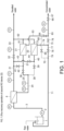
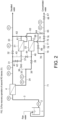
- FIG. 1 and FIG. 2 show the configuration of the desalting device used in the method for operating the desalting device according to the embodiment. It is noted that the flow of water during operation is shown by a thick solid line.
- PI denotes a pressure sensor
- FI denotes a flow rate sensor.
- a first RO device 4 and a second RO device are arranged in series.
- two second RO devices 21 and 22 are arranged in parallel.
- one second RO device 21 is in a normal operation and the other second RO device 22 is in a dilute water passing operation
- the one second RO device 21 is in the dilute water passing operation and the other second RO device 22 is in the normal operation.
- raw water in a raw water tank 1 is supplied to the first RO device 4 via a pump 2 and a pipe 3, and desalted water (permeated water) is taken out as desalted water via a pipe 31, a valve 32, and a pipe 33.
- the concentrated water from the first RO device 4 (first concentrated water) is supplied to the one second RO device 21 via pipes 34 and 35, a valve 36, and a pipe 37.
- the desalted water (permeated water) from the second RO device 21 is merged into the pipe 33 via pipes 61 and 62 and taken out as desalted water.
- the concentrated water from the second RO device 21 is taken out as concentrated water via a pipe 63, a valve 64, a pipe 65, a valve 66, and a pipe 67.
- a pipe 38 branching from the pipe 34 is connected to a water supply port of the other second desalting device 22 via a valve 39 and a pipe 40.
- the valve 39 is shown closed.
- the pipes 31 and 37 are connected by a pipe 41 and a valve 42.
- the pipe 31 and 40 are connected by a pipe 43 and a valve 44.
- the valve 42 is shown closed and the valve 44 is shown open.
- the desalted water from the other second RO device 22 is merged into the pipe 33 via the pipes 73 and 62 and taken out as desalted water.
- the concentrated water from the second RO device 22 is returned to the raw water tank 1 via pipes 74 and 77, a valve 78, and pipes 79 and 71.
- the one second desalting device 21 is in the dilute water passing operation, and the other second desalting device 22 is in the normal operation.
- raw water in the raw water tank 1 is supplied to the first RO device 4 via the pump 2 and the pipe 3, and desalted water (permeated water) is taken out as desalted water via the pipe 31, the valve 32, and the pipe 33.
- the valve 36 is closed and the valve 39 is open.
- the concentrated water from the first RO device 4 (first concentrated water) is supplied to the other second RO device 22 via the pipes 34 and 38, the valve 39, and the pipe 40.
- the desalted water (permeated water) from the second RO device 22 is merged into the pipe 33 via the pipes 73 and 62 and taken out as desalted water.
- the concentrated water from the second RO device 22 flows through the pipes 74 and 75 and the valve 76 into the pipe 65, and is taken out as concentrated water.
- the valve 42 is open and the valve 44 is closed.
- a part of the first desalted water from the pipe 31 is supplied to the water supply port of the one second desalting device 21 via the pipes 42 and 37, and the second desalting device 21 is caused to be in the dilute water passing operation.
- the desalted water from the one second RO device 21 is merged into the pipe 33 via the pipes 61 and 62 and taken out as desalted water.
- the concentrated water from the one second RO device 21 is returned to the raw water tank 1 via the pipes 63 and 68, the valve 69, and the pipes 70 and 71.
- one first RO device 4 and two second RO devices 21 and 22 are arranged, but more than one of each may be arranged. Further, in FIG. 1 and FIG. 2 , when each of the second RO devices 21 and 22 are in the dilute water passing operation, although the dilute water is separated into concentrated water and desalinated water, by closing a valve (not shown) of the desalted water flow passage, the dilute water is not separated into concentrated water and desalted water, and only concentrated water may be discharged from the second RO devices 21 and 22.
- the water passing speed of the dilute water may be appropriately determined corresponding to the clogging state of the desalting device, for example, in the case of a reverse osmosis membrane, the water passing speed is preferably 0.001 to 1 m/s, particularly 0.02 to 0.2 m/s. Specifically, in the case of a 4-inch module, the water passing speed is preferably 300 to 2000 L/Hr per unit, and in the case of an 8-inch module, the water passing speed is preferably 1.8 to 10 m 3 /Hr per unit. Further, the pressure at the concentrated water discharge side of the desalting device is preferably 0.1 to 2 MPa.
- the second RO device through which the dilute water passes is switched. It is noted that 5% is merely an example, and any value selected from between 1% and 5% may be used. In particular, it is preferable to measure the change in permeation flux of the terminal RO which is most concentrated in the second RO device.
- the corrected permeation flux is as described in Example below.
- the predetermined period of time is, for example, 10 to 240 minutes, particularly 30 to 180 minutes, for example, about 90 minutes.
- the dilute water may be any water in which the dissolved salts are less than the saturation solubility.
- a second desalted water permeated water of the second RO device
- a mixture of the permeated water from the first RO device or the second RO device and the raw water may be used as the dilute water.
- a mixture of the permeated water from the first RO device or the second RO device and the first concentrated water may be used as the dilute water.
- the temperature of the dilute water is preferably 20°C or higher, particularly 25° C or higher.
- a scale inhibitor may be added to the dilute water.
- the addition of scale inhibitor may improve the ability to dissolve scale and prevent dissolved scale from re-adhering.
- the scale inhibitor may be appropriately selected depending on the type of desalting device and raw water used.
- a reverse osmosis membrane device is used as the desalting device, and in the case of water to be treated that tends to produce calcium carbonate scale, phosphonic acids such as 2-phosphonobutane-1,2,4-tricarboxylic acid, copolymers of acrylic acid and 2-acrylamido-2-methylpropanesulfonic acid, polyacrylic acid, etc. may be used, and in the case of water to be treated that tends to produce calcium fluoride scale, phosphonic acids such as 2-phosphonobutane-1,2,4-tricarboxylic acid, polyacrylic acid, etc. may be used. Further, the amount of these scale inhibitors to be added is about 10 to 1000 mg/L.
- a pH adjuster may be added to the dilute water to improve the dissolving power of scale and to prevent re-adhesion of dissolved scale.
- dilute water When dilute water is passed through as shown in FIG. 1 , it is preferable to pass the water through the water supply side of the second RO device, but it may also be passed through the concentrated water outlet side of the second RO device. Further, during the time that the dilute water is being passed through the desalting device, the recovery rate may be maintained within a range in which the concentrated water in the desalting device is less than the saturation solubility, and treated water may be produced while the water is being passed through the desalting device.
- the RO devices are installed in two stages, but they may be installed in three or more stages. It is noted that when three or more stages are installed, it is preferable that the desalting device for passing the dilute water is the last one.
- the present invention may be suitably used in cases where calcium fluoride scale or calcium carbonate scale is formed in the second RO device.
- the first concentrated water supplied to the second RO device may be suitably used in the following cases.
- the corrected permeation flux is specified by operating pressure, water temperature, and salinity concentration in the feed water. It is desirable to specify the corrected permeation flux as data indicating the performance of the RO device.
- the corrected permeation flux is generally calculated by the method described in the standardization method for reverse osmosis membrane element and module permeated water amount performance data as specified in JIS K3 8021990.
- Equation (1) the permeated water amount performance data is corrected by the following Equation (1) to calculate a corrected permeation flux F ps .
- F ps Q pa ⁇ P fa ⁇ ⁇ P fba 2 ⁇ P pa ⁇ ⁇ fba + ⁇ pa P fs ⁇ ⁇ P fbs 2 ⁇ P ps ⁇ ⁇ fbs + ⁇ ps ⁇ TCF a TCF s
- Q pa permeated water amount (m 3 /d) under actual operating conditions
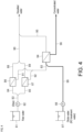
- Raw water in a raw water tank 81 may be feed via a pump 82 and pipe 83.
- the pipe 83 branches into pipes 84 and 85, which are connected to first RO devices 86 and 87.
- the permeated water from the first RO devices 86 and 87 may be taken out as desalted water via pipes 88 and 89 and a joint pipe 90.
- the concentrated water from the first RO devices 86 and 87 is supplied to a second RO device 94 via pipes 91 and 92 and a joint pipe 93.
- the permeated water from the second RO device 94 flows through a pipe 95 and joins the pipe 90.
- the concentrated water from the second RO device 94 is discharged outside the system via a pipe 96.
- the dilute water in a dilute water tank 97 may be supplied to the second RO device 94 via a pump 98, a pipe 99 and the pipe 93.
- the above desalted water was used as the dilute water.
- FIG. 3 shows a normal raw water treatment operation with the pump 82 operating and the pump 98 stopped.
- the raw water is subjected to RO treatment in the first RO device 86 and 87 or further in the second RO device 94, and separated into permeated water (desalted water) and concentrated water.
- FIG. 4 shows a state in which the dilute water is passed through the second RO device 94.
- the pump 82 is stopped, only the pump 98 is operated, and the supply of raw water to the first RO devices 86 and 87 is stopped.
- the dilute water in the dilute water tank 98 is passed through the second RO device 94, whereby scale of the second RO device 94 is dissolved and removed.
- the permeated water is not allowed to flow into the pipe 95 while the dilute water is being passed through the second RO device 94.
- the permeated water may be allowed to flow into the pipe 95 while the dilute water is being passed through the second RO device 94.
- an aqueous solution containing calcium chloride (110 mg/L), sodium bicarbonate (70 mg/L), sodium metasilicate (1610 mg/L), aluminum chloride hexahydrate (0.45 mg/L), ferric chloride (0.4 mg/L), and a scale inhibitor (2-phosphonobutane-1,2,4-tricarboxylic acid) (10 mg/L) was prepared, and further, the pH was adjusted to 5.5 with an aqueous sodium hydroxide solution or an aqueous sulfuric acid solution (water temperature 20°C).
- the permeated water obtained when the simulated raw water was passed through the RO device as shown in FIG. 3 was used.
- the scale inhibitor was added at 10 mg/L.
- Simulated raw water passing step ( FIG. 3 ): Simulated raw water was passed through the reactor so that the initial permeation flux was 0.45 m/D and the water flow rate was 0.1 m/s, and the operation was carried out for 90 minutes with a recovery rate of 73%. (The corrected permeation flux did not decrease substantially after 90 minutes of operation.)
- Dilute water passing step ( FIG. 4 ): After carrying out the simulated raw water passing step for 90 minutes, the dilute water was passed through for 30 minutes at the same pressure and water passing amount as in the simulated raw water passing step. Then, the process returned to the simulated raw water passing step shown in FIG. 3 .
- the simulated raw water passing in FIG. 3 and the dilute water passing in FIG. 4 were alternately conducted in the same manner as in Example 1, except that the passing was switched to the dilute water passing (passing for 30 minutes) in FIG. 4 when the ratio of the flux to the initial standardized permeated water amount reached 90%.
- the ratio F/F 0 of the flux F of the second RO device 94 immediately before the end of the simulated raw water passing step to the initial flux F 0 is shown in FIG. 5 as the "corrected permeated water amount ratio.”
- the performance of the RO membrane may be prevented from decreasing.
- a degraded desalting device is unable to fully recover the performance thereof when it is switched to the passage of the dilute water (Comparative Example 1).
Landscapes
- Chemical & Material Sciences (AREA)
- Engineering & Computer Science (AREA)
- Water Supply & Treatment (AREA)
- Life Sciences & Earth Sciences (AREA)
- Hydrology & Water Resources (AREA)
- Environmental & Geological Engineering (AREA)
- Organic Chemistry (AREA)
- Chemical Kinetics & Catalysis (AREA)
- Nanotechnology (AREA)
- General Chemical & Material Sciences (AREA)
- Separation Using Semi-Permeable Membranes (AREA)
Abstract
Description
- The present invention relates to a method for operating a desalting device, and more particularly to a method for operating desalting devices having a first desalting device and a second desalting device.
- In a desalting device such as a reverse osmosis (RO) membrane, the precipitation of scale such as calcium carbonate, silica, calcium fluoride, etc. and membrane clogging due to organic matter occurs after long-term operation, resulting in a decrease in the performance of the desalting device, such as a decrease in the salt removal rate and a decrease in the permeated water amount. In the case of scale clogging, a method is adopted in which the ion concentration in the raw water is measured and the desalting device is operated so that the saturation index of the concentrated water in the desalting device is not exceeded in order to prevent a decrease in the performance of the desalting device. The saturation index herein generally refers to the logarithmic value of the product of the concentration and ionic strength of each ion species involved in scale formation divided by the solubility product. The desalting device is operated within a range such that the saturation index does not exceed zero. Furthermore, when the saturation index exceeds zero, for example, a scale inhibitor is added to suppress the formation of scale, and a desalting device is operated.
- When the water quality is such that the saturation index is so high that it cannot be controlled even by adding scale inhibitors, chemical cleaning such as acid washing or alkaline washing has conventionally been used to remove the scale. However, in typical cleaning, the equipment is stopped, washed with a cleaning solution, and the cleaning solution is collected before water passing is restarted, resulting in high cleaning costs. Thus, there has been a demand for a desalting device whose performance does not deteriorate even after long-term operation and which does not require chemical cleaning.
- One of the methods for operating the desalting device is the flushing method. Here, flushing refers to an operation of discharging feedwater from the concentrated water discharging pipe to the outside of the system by opening the on-off valve of the concentrated water discharging pipe while continuing to operate the feedwater pump. By passing water through at a faster flow rate than during a normal operation, dirt that clogs the membrane surface may be effectively washed away. Flushing is generally performed 1 to 10 times per day for 30 to 120 seconds per flush. However, flushing for a few minutes at a time is not enough to restore the degraded desalting device, and cleaning with a cleaning solution is ultimately required. Furthermore, when flushing is performed, the on-off valve of the concentrated water pipe is opened, and thus, while flushing is being performed, permeated water cannot be produced, and the recovery rate of the desalting device decreases.
Furthermore, since a salt concentration equivalent to that of the RO feed water is insufficient to restore the desalting device degraded by flushing, it is preferable to perform flushing with water having a low salt concentration. - Another method is to reverse the flow direction of the water to be treated in the module. According to this method, the turbid matter accumulated on the raw water spacer may be easily peeled off, and the stability of the desalting device is improved (
Patent Documents 1 and 2). However, the number of valves required to reverse the flow increases significantly, significantly increasing the initial cost. Furthermore, if a valve fails, the valve is unable to be switched, which significantly reduces the stability of the device. Furthermore, there is no mention of the effect of flow reversal on the separation of scale material. -
Patent Document 3 describes a method of washing scale by passing washing water having low concentrations of F ions, Al ions, and Na ions through the system. In this method, when the ratio of a standardized permeated water amount (corrected permeated water amount) calculated from the flow rate, pressure, and water temperature in the reverse osmosis membrane treatment process to a preset initial standardized permeated water amount reaches a specified value, the passing of cleaning water is switched on. However, it has been found that this method does not sufficiently restore the degraded desalting device. -
- Patent Document 1: Japanese Patent Application Laid-Open (
JP-A) No. 2004-141846. - Patent Document 2: Japanese Patent Application Laid-Open (
JP-A) No. 2004-261724. - Patent Document 3: Japanese Patent Application Laid-Open (
JP-A) No. 2020-121278 - In view of the above problems, an object of the present invention is to provide a method for operating a desalting device that may prevent a decrease in the desalting performance of the desalting device.
- The method for operating a desalting device according to one aspect of the present invention is a method for operating a desalting device having a first desalting device and a second desalting device, including: a normal operation step, in which a water to be treated is supplied to a first desalting device and separated into a first concentrated water and a first desalted water, and the first concentrated water is supplied to a second desalting device and separated into a second concentrated water and a second desalted water; and a dilute water passing operation step, in which a dilute water having a lower concentration than the first concentrated water is passed through the second desalting device before a corrected permeated water amount of the second desalting device is reduced.
- In one aspect of the present invention, a plurality of the second desalting devices are arranged in parallel, and while the first desalting device and some of the second desalting devices are performing the normal operation step, other second desalting devices perform the dilute water passing operation step.
- The method for operating a desalting device according to one aspect of the present invention is a method for operating a desalting device having a first desalting device and two second desalting devices, alternately performs: a first water passing pattern, in which a water to be treated is supplied to a first desalting device and separated into a first concentrated water and a first desalted water, the first concentrated water is supplied to one second desalting device and separated into a second concentrated water and a second desalted water, and a dilute water having a lower concentration than the first concentrated water is passed through other second desalting device; and a second water passing pattern, in which a water to be treated is supplied to a first desalting device and separated into a first concentrated water and a first desalted water, the first concentrated water is supplied to other second desalting device and separated into a second concentrated water and a second desalted water, and a dilute water having a lower concentration than the first concentrated water is passed through one second desalting device. The first water passing pattern and the second water passing pattern are switched at a frequency of once every 30 to 180 minutes.
- In one aspect of the present invention, a water having a dissolved salt concentration less than a saturation solubility is used as a dilute water.
- In one aspect of the present invention, a desalted water from the first desalting device or from the first desalting device and the second desalting device is used as a dilute water.
- In one aspect of the present invention, a scale inhibitor is added to a dilute water.
- In one aspect of the present invention, the desalting device is a reverse osmosis membrane device.
- In one aspect of the present invention, a dilute water has a water temperature of 25°C or higher.
- In one aspect of the present invention, the first concentrated water has a water temperature of 20°C or higher, a pH of <6.0, a calcium ion concentration of 50 to 500 mg/L, an aluminum ion concentration of 0.01 to 0.5 mg/L, an iron ion concentration of 0.01 to 0.25 mg/L, and a silica concentration of 500 to 1500 mg/L.
- In a normal operation step of the method for operating a desalting device of the present invention, the water to be treated is passed through a first desalting device so as to be separated into a first desalted water and a first concentrated water, and the first concentrated water is passed through a second desalting device so as to be separated into a second desalted water and a second concentrated water. By passing a dilute water through the second desalting device before the desalting performance of the second desalting device is substantially deteriorated by performing the normal operation step, the desalting performance of the second desalting device may be prevented from being deteriorated.
- It is noted that in an aspect in which a desalted water from the first or second desalting device is used as dilute water when the second desalting device performs a flux recovery operation, auxiliary equipment such as a tank is not required, and the device configuration is simplified. Further, by using water having a low salt concentration, that is, the permeated water from the first desalting device, as the dilute water, the scale adhering to the second desalting device may be dissolved and removed more sufficiently than when the water to be treated is used as the dilute water.
-
- [
FIG. 1 ] is a flow diagram illustrating the method for operating the desalting device according to an embodiment. - [
FIG. 2 ] is a flow diagram illustrating the method for operating the desalting device according to an embodiment. - [
FIG. 3 ] is a flow diagram illustrating the method for operating the desalting device according to an example. - [
FIG. 4 ] is a flow diagram illustrating the method for operating the desalting device according to an example. - [
FIG. 5 ] is a graph showing the results of the example and the comparative example. - The first embodiment is described below with reference to
FIG. 1 andFIG. 2 . In this embodiment, a reverse osmosis membrane device (RO device) is taken as an example of the desalting device, but the present invention is not limited thereto. It is noted that the reverse osmosis membrane is preferably an aromatic polyamide reverse osmosis membrane, but is not limited thereto. Examples of desalting devices other than reverse osmosis membrane devices include nanofiltration membrane devices, forward osmosis membrane devices, membrane distillation devices, electrodialysis devices, and electrodeionization devices. Further, examples of water to be treated include industrial water with a salt concentration of about 10 to 5000 mg/L, particularly about 50 to 1000 mg/L, well water, fluoride-containing waste water, and the like, but are not limited thereto. -
FIG. 1 andFIG. 2 show the configuration of the desalting device used in the method for operating the desalting device according to the embodiment. It is noted that the flow of water during operation is shown by a thick solid line. In the figure, PI denotes a pressure sensor, and FI denotes a flow rate sensor. - In this embodiment, a
first RO device 4 and a second RO device are arranged in series. As the second RO device, twosecond RO devices FIG. 1 , onesecond RO device 21 is in a normal operation and the othersecond RO device 22 is in a dilute water passing operation, and inFIG. 2 , the onesecond RO device 21 is in the dilute water passing operation and the othersecond RO device 22 is in the normal operation. - As shown in
FIG. 1 , raw water in araw water tank 1 is supplied to thefirst RO device 4 via apump 2 and apipe 3, and desalted water (permeated water) is taken out as desalted water via apipe 31, avalve 32, and apipe 33. - The concentrated water from the first RO device 4 (first concentrated water) is supplied to the one
second RO device 21 viapipes valve 36, and apipe 37. - The desalted water (permeated water) from the
second RO device 21 is merged into thepipe 33 viapipes second RO device 21 is taken out as concentrated water via apipe 63, avalve 64, apipe 65, avalve 66, and apipe 67. - A
pipe 38 branching from thepipe 34 is connected to a water supply port of the othersecond desalting device 22 via avalve 39 and apipe 40. InFIG. 1 , thevalve 39 is shown closed. - The
pipes pipe 41 and avalve 42. Thepipe pipe 43 and avalve 44. InFIG. 1 , thevalve 42 is shown closed and thevalve 44 is shown open. Thus, a part of the first desalted water from thepipe 31 is supplied to the water supply port of thesecond desalting device 22 via thepipes second desalting device 22 is caused to be in the dilute water passing operation. - During the dilute water passing operation of the other
second RO device 22, the desalted water from the othersecond RO device 22 is merged into thepipe 33 via thepipes second RO device 22 is returned to theraw water tank 1 viapipes valve 78, andpipes - Contrary to
FIG. 1 , inFIG. 2 , the onesecond desalting device 21 is in the dilute water passing operation, and the othersecond desalting device 22 is in the normal operation. In this case as well, raw water in theraw water tank 1 is supplied to thefirst RO device 4 via thepump 2 and thepipe 3, and desalted water (permeated water) is taken out as desalted water via thepipe 31, thevalve 32, and thepipe 33. - In
FIG. 2 , thevalve 36 is closed and thevalve 39 is open. Thus, the concentrated water from the first RO device 4 (first concentrated water) is supplied to the othersecond RO device 22 via thepipes valve 39, and thepipe 40. - The desalted water (permeated water) from the
second RO device 22 is merged into thepipe 33 via thepipes second RO device 22 flows through thepipes valve 76 into thepipe 65, and is taken out as concentrated water. - In addition, in
FIG. 2 , thevalve 42 is open and thevalve 44 is closed. Thus, a part of the first desalted water from thepipe 31 is supplied to the water supply port of the onesecond desalting device 21 via thepipes second desalting device 21 is caused to be in the dilute water passing operation. The desalted water from the onesecond RO device 21 is merged into thepipe 33 via thepipes second RO device 21 is returned to theraw water tank 1 via thepipes valve 69, and thepipes - In this way, in the method for operating the desalting device in
FIG. 1 andFIG. 2 , by operating one of the twosecond desalting devices - In
FIG. 1 andFIG. 2 , onefirst RO device 4 and twosecond RO devices FIG. 1 andFIG. 2 , when each of thesecond RO devices second RO devices - The water passing speed of the dilute water may be appropriately determined corresponding to the clogging state of the desalting device, for example, in the case of a reverse osmosis membrane, the water passing speed is preferably 0.001 to 1 m/s, particularly 0.02 to 0.2 m/s. Specifically, in the case of a 4-inch module, the water passing speed is preferably 300 to 2000 L/Hr per unit, and in the case of an 8-inch module, the water passing speed is preferably 1.8 to 10 m3/Hr per unit. Further, the pressure at the concentrated water discharge side of the desalting device is preferably 0.1 to 2 MPa.
- Before the corrected permeation flux of the second RO device decreases from the initial operation stage, specifically, before the same decreases by 5% or more from the initial operation stage, the second RO device through which the dilute water passes is switched. It is noted that 5% is merely an example, and any value selected from between 1% and 5% may be used. In particular, it is preferable to measure the change in permeation flux of the terminal RO which is most concentrated in the second RO device. The corrected permeation flux is as described in Example below.
- Rather than detecting the decrease in the corrected permeation flux, it is also possible to operate the one second RO devices in normal operation and the other second RO device in the dilute water passing operation for a predetermined period of time, and then switch the one second RO device to the normal operation and the other second RO device to the dilute water passing operation. The predetermined period of time is, for example, 10 to 240 minutes, particularly 30 to 180 minutes, for example, about 90 minutes.
- In the above embodiment, although the first desalted water is used as the dilute water, in the present invention, the dilute water may be any water in which the dissolved salts are less than the saturation solubility. Thus, a second desalted water (permeated water of the second RO device) may be used as the dilute water. Moreover, a mixture of the permeated water from the first RO device or the second RO device and the raw water may be used as the dilute water. Furthermore, a mixture of the permeated water from the first RO device or the second RO device and the first concentrated water may be used as the dilute water. The saturation solubility of a dissolved salt is the solubility product Ksp of a scale species XY with respect to the molar concentration of X+ [X+] and the molar concentration of Y- [Y-], where [X+][Y-] = Ksp is satisfied.
- It is noted that, since the recovery effect of the permeated water amount is small when the temperature of the dilute water is low, the temperature of the dilute water is preferably 20°C or higher, particularly 25° C or higher.
- A scale inhibitor may be added to the dilute water. The addition of scale inhibitor may improve the ability to dissolve scale and prevent dissolved scale from re-adhering.
- The scale inhibitor may be appropriately selected depending on the type of desalting device and raw water used. A reverse osmosis membrane device is used as the desalting device, and in the case of water to be treated that tends to produce calcium carbonate scale, phosphonic acids such as 2-phosphonobutane-1,2,4-tricarboxylic acid, copolymers of acrylic acid and 2-acrylamido-2-methylpropanesulfonic acid, polyacrylic acid, etc. may be used, and in the case of water to be treated that tends to produce calcium fluoride scale, phosphonic acids such as 2-phosphonobutane-1,2,4-tricarboxylic acid, polyacrylic acid, etc. may be used. Further, the amount of these scale inhibitors to be added is about 10 to 1000 mg/L.
- It is noted that a pH adjuster may be added to the dilute water to improve the dissolving power of scale and to prevent re-adhesion of dissolved scale.
- When dilute water is passed through as shown in
FIG. 1 , it is preferable to pass the water through the water supply side of the second RO device, but it may also be passed through the concentrated water outlet side of the second RO device. Further, during the time that the dilute water is being passed through the desalting device, the recovery rate may be maintained within a range in which the concentrated water in the desalting device is less than the saturation solubility, and treated water may be produced while the water is being passed through the desalting device. - In the above embodiment, the RO devices are installed in two stages, but they may be installed in three or more stages. It is noted that when three or more stages are installed, it is preferable that the desalting device for passing the dilute water is the last one.
- The present invention may be suitably used in cases where calcium fluoride scale or calcium carbonate scale is formed in the second RO device. Specifically, the first concentrated water supplied to the second RO device may be suitably used in the following cases.
-
Water temperature 20°C or higher pH < 6.0 - Calcium ion concentration: 50 to 500 mg/L (preferably 100 to 250 mg/L)
- Aluminum ion concentration: 0.01 to 0.5 mg/L (preferably 0.1 to 0.25 mg/L)
- Iron ion concentration: 0.01 to 0.25 mg/L (preferably 0.1 to 0.25 mg/L)
- Silica concentration: 500 to 1500 mg/L (preferably 700 to 1200 mg/L)
- Using the test equipment shown in
FIG. 3 andFIG. 4 , a simulated raw water treatment operation (FIG. 3 ) and a dilute water passing operation to the second RO device (FIG. 4 ) were alternately performed. It is noted that in this test, the corrected permeation flux value was used as the flux value. - Since the actual permeation flux is affected by operating pressure, water temperature, and salinity concentration in the feed water, it is desirable to specify the corrected permeation flux as data indicating the performance of the RO device.
- Here, the corrected permeation flux is generally calculated by the method described in the standardization method for reverse osmosis membrane element and module permeated water amount performance data as specified in JIS K3 8021990.
- That is, the permeated water amount performance data is corrected by the following Equation (1) to calculate a corrected permeation flux Fps.
[Expression 1]
Where, Qpa: permeated water amount (m3/d) under actual operating conditions - Pfa: Operating pressure (kPa) under actual operating conditions
- ΔPfba: Module differential pressure (kPa) under actual operating conditions
- Ppa: Pressure (kPa) on the permeated water side under actual operating conditions
- Πfba: Osmotic pressure (kPa) of the average solute concentration on the supply side and the concentrated side under actual operating conditions
- TCFa: Temperature conversion coefficient under actual operating conditions
- Pfs: Operating pressure (kPa) under standard operating conditions
- ΔPfbs: Module differential pressure (kPa) under standard operating conditions
- Pps: Pressure (kPa) on the permeated water side under standard operating conditions
- Πfbs: Osmotic pressure (kPa) of the average solute concentration on the supply side and the concentrated side under standard operating conditions
- TCFs: Temperature conversion coefficient under standard operating conditions
- Raw water in a
raw water tank 81 may be feed via apump 82 andpipe 83. Thepipe 83 branches intopipes first RO devices first RO devices pipes joint pipe 90. - The concentrated water from the
first RO devices second RO device 94 viapipes joint pipe 93. The permeated water from thesecond RO device 94 flows through apipe 95 and joins thepipe 90. The concentrated water from thesecond RO device 94 is discharged outside the system via apipe 96. - The dilute water in a
dilute water tank 97 may be supplied to thesecond RO device 94 via apump 98, apipe 99 and thepipe 93. In this test example, the above desalted water was used as the dilute water. -
FIG. 3 shows a normal raw water treatment operation with thepump 82 operating and thepump 98 stopped. The raw water is subjected to RO treatment in thefirst RO device second RO device 94, and separated into permeated water (desalted water) and concentrated water. -
FIG. 4 shows a state in which the dilute water is passed through thesecond RO device 94. InFIG. 4 , thepump 82 is stopped, only thepump 98 is operated, and the supply of raw water to thefirst RO devices dilute water tank 98 is passed through thesecond RO device 94, whereby scale of thesecond RO device 94 is dissolved and removed. - It is noted that in
FIG. 4 , the permeated water is not allowed to flow into thepipe 95 while the dilute water is being passed through thesecond RO device 94. However, the permeated water may be allowed to flow into thepipe 95 while the dilute water is being passed through thesecond RO device 94. - As a simulated raw water, an aqueous solution containing calcium chloride (110 mg/L), sodium bicarbonate (70 mg/L), sodium metasilicate (1610 mg/L), aluminum chloride hexahydrate (0.45 mg/L), ferric chloride (0.4 mg/L), and a scale inhibitor (2-phosphonobutane-1,2,4-tricarboxylic acid) (10 mg/L) was prepared, and further, the pH was adjusted to 5.5 with an aqueous sodium hydroxide solution or an aqueous sulfuric acid solution (
water temperature 20°C). - As the dilute water, the permeated water obtained when the simulated raw water was passed through the RO device as shown in
FIG. 3 was used. The scale inhibitor was added at 10 mg/L. - The above-mentioned simulated raw water and simulated dilute water were passed through the desalting device of
FIG. 3 andFIG. 4 . - Simulated raw water passing step (
FIG. 3 ): Simulated raw water was passed through the reactor so that the initial permeation flux was 0.45 m/D and the water flow rate was 0.1 m/s, and the operation was carried out for 90 minutes with a recovery rate of 73%. (The corrected permeation flux did not decrease substantially after 90 minutes of operation.) - Dilute water passing step (
FIG. 4 ): After carrying out the simulated raw water passing step for 90 minutes, the dilute water was passed through for 30 minutes at the same pressure and water passing amount as in the simulated raw water passing step. Then, the process returned to the simulated raw water passing step shown inFIG. 3 . - In the simulated raw water passing step of
FIG. 3 , the simulated raw water passing inFIG. 3 and the dilute water passing inFIG. 4 were alternately conducted in the same manner as in Example 1, except that the passing was switched to the dilute water passing (passing for 30 minutes) inFIG. 4 when the ratio of the flux to the initial standardized permeated water amount reached 90%. - The ratio F/F0 of the flux F of the
second RO device 94 immediately before the end of the simulated raw water passing step to the initial flux F0 is shown inFIG. 5 as the "corrected permeated water amount ratio." As shown inFIG. 5 , by performing the dilute water passing step before the flux of the RO membrane decreases, as in Example 1, the performance of the RO membrane may be prevented from decreasing. In contrast, when the ratio of the flux to the initial standardized permeated water amount reaches 90%, a degraded desalting device is unable to fully recover the performance thereof when it is switched to the passage of the dilute water (Comparative Example 1). - Although the present invention has been described in detail with reference to a particular aspect, it is apparent to a person skilled in the art that various modifications can be made therein without departing from the spirit and scope of the present invention.
The present application is based onJapanese Patent Application No. 2022-032755 filed on March 3, 2022 -
- 1 Raw water tank
- 4 First RO device
- 21, 22 Second RO device
- 81 Raw water tank
- 86, 87 First RO device
- 94 Second RO device
- 97 Dilute water tank
Claims (9)
- A method for operating a desalting device having a first desalting device and a second desalting device, comprising:a normal operation step, in which a water to be treated is supplied to a first desalting device and separated into a first concentrated water and a first desalted water, and the first concentrated water is supplied to a second desalting device and separated into a second concentrated water and a second desalted water; anda dilute water passing operation step, in which a dilute water having a lower concentration than the first concentrated water is passed through the second desalting device before a corrected permeated water amount of the second desalting device is reduced.
- The method for operating the desalting device according to claim 1, wherein a plurality of the second desalting devices are arranged in parallel, and while the first desalting device and some of the second desalting devices are performing the normal operation step, other second desalting devices perform the dilute water passing operation step.
- The method for operating the desalting device according to claim 1, which is a method for operating a desalting device having a first desalting device and two second desalting devices, alternately performing:a first water passing pattern, in which a water to be treated is supplied to a first desalting device and separated into a first concentrated water and a first desalted water, the first concentrated water is supplied to one second desalting device and separated into a second concentrated water and a second desalted water, and a dilute water having a lower concentration than the first concentrated water is passed through other second desalting device; anda second water passing pattern, in which a water to be treated is supplied to a first desalting device and separated into a first concentrated water and a first desalted water, the first concentrated water is supplied to other second desalting device and separated into a second concentrated water and a second desalted water, and a dilute water having a lower concentration than the first concentrated water is passed through one second desalting device,wherein the first water passing pattern and the second water passing pattern are switched at a frequency of once every 30 to 180 minutes.
- The method for operating the desalting device according to any one of claims 1 to 3, wherein a water having a dissolved salt concentration less than a saturation solubility is used as a dilute water.
- The method for operating the desalting device according to any one of claims 1 to 3, wherein a desalted water from the first desalting device or from the first desalting device and the second desalting device is used as a dilute water.
- The method for operating the desalting device according to any one of claims 1 to 5, wherein a scale inhibitor is added to a dilute water.
- The method for operating the desalting device according to any one of claims 1 to 6, wherein the desalting device is a reverse osmosis membrane device.
- The method for operating the desalting device according to any one of claims 1 to 7, wherein a dilute water has a water temperature of 25°C or higher.
- The method for operating the desalting device according to any one of claims 1 to 8, wherein the first concentrated water has a water temperature of 20°C or higher, a pH of <6.0, a calcium ion concentration of 50 to 500 mg/L, an aluminum ion concentration of 0.01 to 0.5 mg/L, an iron ion concentration of 0.01 to 0.25 mg/L, and a silica concentration of 500 to 1500 mg/L.
Applications Claiming Priority (2)
| Application Number | Priority Date | Filing Date | Title |
|---|---|---|---|
| JP2022032755A JP7318755B1 (en) | 2022-03-03 | 2022-03-03 | Operation method of desalting equipment |
| PCT/JP2023/003390 WO2023166905A1 (en) | 2022-03-03 | 2023-02-02 | Method for operating desalting device |
Publications (2)
| Publication Number | Publication Date |
|---|---|
| EP4487939A1 true EP4487939A1 (en) | 2025-01-08 |
| EP4487939A4 EP4487939A4 (en) | 2026-04-01 |
Family
ID=87469677
Family Applications (1)
| Application Number | Title | Priority Date | Filing Date |
|---|---|---|---|
| EP23763167.6A Pending EP4487939A4 (en) | 2022-03-03 | 2023-02-02 | Method for operating desalting device |
Country Status (7)
| Country | Link |
|---|---|
| US (1) | US20250136473A1 (en) |
| EP (1) | EP4487939A4 (en) |
| JP (1) | JP7318755B1 (en) |
| KR (1) | KR20240157640A (en) |
| CN (1) | CN118647579A (en) |
| TW (1) | TW202335732A (en) |
| WO (1) | WO2023166905A1 (en) |
Family Cites Families (12)
| Publication number | Priority date | Publication date | Assignee | Title |
|---|---|---|---|---|
| JP4225471B2 (en) | 2003-03-03 | 2009-02-18 | オルガノ株式会社 | Operation method of multistage separation membrane module |
| JP4251879B2 (en) | 2002-08-29 | 2009-04-08 | オルガノ株式会社 | Operation method of separation membrane module |
| JP6142937B1 (en) | 2016-03-18 | 2017-06-07 | 栗田工業株式会社 | Reverse osmosis membrane device operation management method and reverse osmosis membrane treatment system |
| JP7454330B2 (en) * | 2018-06-20 | 2024-03-22 | オルガノ株式会社 | Boron removal method in treated water, boron removal system, ultrapure water production system, and boron concentration measurement method |
| JP7116691B2 (en) * | 2019-01-31 | 2022-08-10 | オルガノ株式会社 | Water treatment method and water treatment equipment |
| JP7200014B2 (en) * | 2019-03-13 | 2023-01-06 | オルガノ株式会社 | Pure water production device and pure water production method |
| JP2021037481A (en) | 2019-09-04 | 2021-03-11 | オルガノ株式会社 | Water treatment system and water treatment method |
| JP2021037480A (en) | 2019-09-04 | 2021-03-11 | オルガノ株式会社 | Water treatment system and water treatment method |
| JP7526611B2 (en) | 2020-08-14 | 2024-08-01 | 東京エレクトロン株式会社 | Processing system and processing method |
| JP7407750B2 (en) * | 2020-09-09 | 2024-01-04 | 栗田工業株式会社 | How to operate desalination equipment |
| US20230285903A1 (en) * | 2020-09-09 | 2023-09-14 | Kurita Water Industries Ltd. | Method for operating desalting device |
| CN112919693B (en) | 2021-01-21 | 2022-09-13 | 倍杰特集团股份有限公司 | Full-membrane-process desalted water treatment system and treatment method thereof |
-
2022
- 2022-03-03 JP JP2022032755A patent/JP7318755B1/en active Active
-
2023
- 2023-02-02 WO PCT/JP2023/003390 patent/WO2023166905A1/en not_active Ceased
- 2023-02-02 US US18/836,749 patent/US20250136473A1/en active Pending
- 2023-02-02 EP EP23763167.6A patent/EP4487939A4/en active Pending
- 2023-02-02 CN CN202380020411.4A patent/CN118647579A/en active Pending
- 2023-02-02 KR KR1020247023716A patent/KR20240157640A/en active Pending
- 2023-02-09 TW TW112104616A patent/TW202335732A/en unknown
Also Published As
| Publication number | Publication date |
|---|---|
| JP2023128417A (en) | 2023-09-14 |
| KR20240157640A (en) | 2024-11-01 |
| TW202335732A (en) | 2023-09-16 |
| EP4487939A4 (en) | 2026-04-01 |
| WO2023166905A1 (en) | 2023-09-07 |
| JP7318755B1 (en) | 2023-08-01 |
| CN118647579A (en) | 2024-09-13 |
| US20250136473A1 (en) | 2025-05-01 |
Similar Documents
| Publication | Publication Date | Title |
|---|---|---|
| CN105408008B (en) | The incrustation scale detection means and method and water reuse (treatment processing system of enrichment facility | |
| EP1691915B1 (en) | Method and system for increasing recovery and preventing precipitation fouling in pressure-driven membrane processes | |
| US20230285903A1 (en) | Method for operating desalting device | |
| JP6395844B2 (en) | Adhesion monitoring device for water treatment device, water treatment device and operation method thereof, and cleaning method for water treatment device | |
| JP2012192374A (en) | Water treatment apparatus | |
| JP5961916B2 (en) | Water treatment equipment | |
| JP2020121278A (en) | Water treatment method and water treatment device | |
| JP5757110B2 (en) | Water treatment method and water treatment system | |
| US20250136473A1 (en) | Method for operating desalting device | |
| JP2005288442A (en) | Membrane module cleaning method | |
| JP7407750B2 (en) | How to operate desalination equipment | |
| WO2016035175A1 (en) | Water treatment device and operating method for water treatment device | |
| TWI893203B (en) | How to operate the desalination device | |
| JP2006043655A (en) | Water treating apparatus and operation method therefor | |
| JP7744460B1 (en) | Water treatment device and water treatment method | |
| JP2001314734A (en) | Cleaning method for membrane separation equipment | |
| JP2022041621A (en) | Separation membrane washing method and water treatment system | |
| JP2024027297A (en) | Water treatment method and water treatment equipment | |
| JP2016112518A (en) | Deoxidation apparatus, and production method of deoxidized water | |
| Nam et al. | Evaluation on cleaning efficiency and membrane fouling by permeation coefficient and concentration polarization factor in pilot-scale SWRO processes |
Legal Events
| Date | Code | Title | Description |
|---|---|---|---|
| STAA | Information on the status of an ep patent application or granted ep patent |
Free format text: STATUS: THE INTERNATIONAL PUBLICATION HAS BEEN MADE |
|
| PUAI | Public reference made under article 153(3) epc to a published international application that has entered the european phase |
Free format text: ORIGINAL CODE: 0009012 |
|
| STAA | Information on the status of an ep patent application or granted ep patent |
Free format text: STATUS: REQUEST FOR EXAMINATION WAS MADE |
|
| 17P | Request for examination filed |
Effective date: 20240809 |
|
| AK | Designated contracting states |
Kind code of ref document: A1 Designated state(s): AL AT BE BG CH CY CZ DE DK EE ES FI FR GB GR HR HU IE IS IT LI LT LU LV MC ME MK MT NL NO PL PT RO RS SE SI SK SM TR |
|
| DAV | Request for validation of the european patent (deleted) | ||
| DAX | Request for extension of the european patent (deleted) | ||
| A4 | Supplementary search report drawn up and despatched |
Effective date: 20260302 |
|
| RIC1 | Information provided on ipc code assigned before grant |
Ipc: B01D 61/12 20060101AFI20260224BHEP Ipc: B01D 61/58 20060101ALI20260224BHEP Ipc: C02F 1/44 20230101ALI20260224BHEP |