EP4487906A1 - System und verfahren zur planung einer strahlenbehandlung - Google Patents
System und verfahren zur planung einer strahlenbehandlung Download PDFInfo
- Publication number
- EP4487906A1 EP4487906A1 EP24175404.3A EP24175404A EP4487906A1 EP 4487906 A1 EP4487906 A1 EP 4487906A1 EP 24175404 A EP24175404 A EP 24175404A EP 4487906 A1 EP4487906 A1 EP 4487906A1
- Authority
- EP
- European Patent Office
- Prior art keywords
- objective
- pass
- value
- parameters
- reference objective
- Prior art date
- Legal status (The legal status is an assumption and is not a legal conclusion. Google has not performed a legal analysis and makes no representation as to the accuracy of the status listed.)
- Pending
Links
Images




Classifications
-
- A—HUMAN NECESSITIES
- A61—MEDICAL OR VETERINARY SCIENCE; HYGIENE
- A61N—ELECTROTHERAPY; MAGNETOTHERAPY; RADIATION THERAPY; ULTRASOUND THERAPY
- A61N5/00—Radiation therapy
- A61N5/10—X-ray therapy; Gamma-ray therapy; Particle-irradiation therapy
- A61N5/1001—X-ray therapy; Gamma-ray therapy; Particle-irradiation therapy using radiation sources introduced into or applied onto the body; brachytherapy
-
- A—HUMAN NECESSITIES
- A61—MEDICAL OR VETERINARY SCIENCE; HYGIENE
- A61N—ELECTROTHERAPY; MAGNETOTHERAPY; RADIATION THERAPY; ULTRASOUND THERAPY
- A61N5/00—Radiation therapy
- A61N5/10—X-ray therapy; Gamma-ray therapy; Particle-irradiation therapy
- A61N5/103—Treatment planning systems
-
- A—HUMAN NECESSITIES
- A61—MEDICAL OR VETERINARY SCIENCE; HYGIENE
- A61N—ELECTROTHERAPY; MAGNETOTHERAPY; RADIATION THERAPY; ULTRASOUND THERAPY
- A61N5/00—Radiation therapy
- A61N5/10—X-ray therapy; Gamma-ray therapy; Particle-irradiation therapy
- A61N5/103—Treatment planning systems
- A61N5/1031—Treatment planning systems using a specific method of dose optimization
-
- A—HUMAN NECESSITIES
- A61—MEDICAL OR VETERINARY SCIENCE; HYGIENE
- A61N—ELECTROTHERAPY; MAGNETOTHERAPY; RADIATION THERAPY; ULTRASOUND THERAPY
- A61N5/00—Radiation therapy
- A61N5/10—X-ray therapy; Gamma-ray therapy; Particle-irradiation therapy
- A61N5/103—Treatment planning systems
- A61N5/1039—Treatment planning systems using functional images, e.g. PET or MRI
-
- A—HUMAN NECESSITIES
- A61—MEDICAL OR VETERINARY SCIENCE; HYGIENE
- A61N—ELECTROTHERAPY; MAGNETOTHERAPY; RADIATION THERAPY; ULTRASOUND THERAPY
- A61N5/00—Radiation therapy
- A61N5/10—X-ray therapy; Gamma-ray therapy; Particle-irradiation therapy
- A61N5/1042—X-ray therapy; Gamma-ray therapy; Particle-irradiation therapy with spatial modulation of the radiation beam within the treatment head
- A61N5/1045—X-ray therapy; Gamma-ray therapy; Particle-irradiation therapy with spatial modulation of the radiation beam within the treatment head using a multi-leaf collimator, e.g. for intensity modulated radiation therapy or IMRT
-
- G—PHYSICS
- G16—INFORMATION AND COMMUNICATION TECHNOLOGY [ICT] SPECIALLY ADAPTED FOR SPECIFIC APPLICATION FIELDS
- G16H—HEALTHCARE INFORMATICS, i.e. INFORMATION AND COMMUNICATION TECHNOLOGY [ICT] SPECIALLY ADAPTED FOR THE HANDLING OR PROCESSING OF MEDICAL OR HEALTHCARE DATA
- G16H20/00—ICT specially adapted for therapies or health-improving plans, e.g. for handling prescriptions, for steering therapy or for monitoring patient compliance
- G16H20/40—ICT specially adapted for therapies or health-improving plans, e.g. for handling prescriptions, for steering therapy or for monitoring patient compliance relating to mechanical, radiation or invasive therapies, e.g. surgery, laser therapy, dialysis or acupuncture
-
- A—HUMAN NECESSITIES
- A61—MEDICAL OR VETERINARY SCIENCE; HYGIENE
- A61N—ELECTROTHERAPY; MAGNETOTHERAPY; RADIATION THERAPY; ULTRASOUND THERAPY
- A61N5/00—Radiation therapy
- A61N5/10—X-ray therapy; Gamma-ray therapy; Particle-irradiation therapy
- A61N5/103—Treatment planning systems
- A61N5/1031—Treatment planning systems using a specific method of dose optimization
- A61N2005/1034—Monte Carlo type methods; particle tracking
-
- A—HUMAN NECESSITIES
- A61—MEDICAL OR VETERINARY SCIENCE; HYGIENE
- A61N—ELECTROTHERAPY; MAGNETOTHERAPY; RADIATION THERAPY; ULTRASOUND THERAPY
- A61N5/00—Radiation therapy
- A61N5/10—X-ray therapy; Gamma-ray therapy; Particle-irradiation therapy
- A61N2005/1085—X-ray therapy; Gamma-ray therapy; Particle-irradiation therapy characterised by the type of particles applied to the patient
- A61N2005/1087—Ions; Protons
-
- A—HUMAN NECESSITIES
- A61—MEDICAL OR VETERINARY SCIENCE; HYGIENE
- A61N—ELECTROTHERAPY; MAGNETOTHERAPY; RADIATION THERAPY; ULTRASOUND THERAPY
- A61N5/00—Radiation therapy
- A61N5/10—X-ray therapy; Gamma-ray therapy; Particle-irradiation therapy
- A61N2005/1085—X-ray therapy; Gamma-ray therapy; Particle-irradiation therapy characterised by the type of particles applied to the patient
- A61N2005/1089—Electrons
Definitions
- radiotherapy comprises using a linear accelerator (“linac”), whereby a targeted region is irradiated by high-energy particles (e.g., electrons, high-energy photons, and the like).
- high-energy particles e.g., electrons, high-energy photons, and the like.
- radiotherapy is provided using a heavy charged particle accelerator (e.g., protons, carbon ions, and the like).
- the cost function 102 is a mathematical formulation that relates the parameters 103 and the model 101.
- the cost function may be referred to as an objective function.
- the cost function 102 relates the dose distribution in the model 101 to a single value (the cost function value 109).
- the cost function value 109 For example, when the reference objective is "the mean dose for the bladder is less than 30 Gy", the cost function mathematically formulates and computes the mean dose for the bladder as a function of parameters 103, and compares the achieved mean dose to the reference of 30 Gy.
- the optimiser 107 seeks parameters that would minimize the difference between the achieved mean dose and the reference mean dose.
- the cost function value quantifies how close the dose in the model is to a desired value.
- the cost function value 109 is value of the cost function 102 when evaluated with the set of optimised parameters.
- the cost function value 109 is calculated by the optimiser during optimisation.
- the cost function value 109 may be referred to as a penalty.
- the cost function value 109 is output by the optimiser.
- the cost function value 109 represents a penalty for violating an objective or constraint.
- the penalty is evaluated by the optimiser during optimisation.
- constrained optimisation only objectives contribute to the cost function.
- the constraint 105 comprise one or more conditions that the optimised parameters 111 must satisfy.
- the constraint may be a hard constraint (which set conditions that the parameters are required to satisfy) or soft constraint (which have some variable values that are penalised in the cost function if some conditions are not satisfied).
- Constraints restrict the set of solutions that are obtainable. Constraints are used to define what is physically or clinically acceptable rather than what is mathematically possible. For example, for IMRT, a constraint may be that the weights of the beamlets must be non-negative (since a negative beamlet weight is not possible). Note that the constraint 105 is an optional feature.
- the reference objective 104 represents a goal to be achieved.
- the reference objective comprises a dose-based objective and/or a volume-based objective.
- a dose objective may be defined in terms of a dose value (in Gy).
- An example of a dose objective may be stated as "the average dose to an OAR should be less than or equal to 30Gy".
- a volume-based objective may comprise a relative volume or an absolute volume.
- the relative volume represents a fraction of a volume. For example, the relative volume is a percentage.
- the absolute volume may be defined in terms of physical dimensions (e.g., in mm, cm, mm 3 , cm 3 , etc).
- a volume based objective may be stated as "at least 90% of the volume of a PTV should meet some criterion".
- a reference objective 104 may be stated as "at least X% of a first region receives at least Y Gy". The optimiser 107 may then determine optimised parameters 111 that result in an achieved goal value 113 that is close to the reference objective 104.
- the reference objective may be referred to as a treatment-planning objective.
- the reference objective 104 is an optional feature.
- the reference objective 104 comprises an indication of a cost function 102 to be used.
- the reference objective comprises an indication of an anatomical structure to which the goal to be achieved is applicable.
- the reference objective is an anatomy specific function that establishes the dose and/or biological response goal.
- Constraints 105 are anatomy-specific functions that must be met. They may be referred to as hard constraints. When constraints are used together with objectives, constraints are always met, while objectives may not be met (instead, they are goals that the optimiser tries to achieve).
- the cost function 102 together with the model 101, the parameters 103, constraints 105 (optional) and reference objective 104 (optional), define the problem to be solved.
- the cost function 102, constraints 105, reference objective 104 may be referred to as a treatment-planning objective.
- the treatment-planning objective may be associated to an anatomical structure.
- a treatment-planning objective may comprise any of cost function 102, constraint 105, reference objective 104.
- An example of a treatment-planning objective may be stated as "97% of the volume of a PTV should receive a dose of at least 30 Gy, using a "Target Penalty" cost function".
- Other examples of treatment-planning objectives are listed in row m to x in Table.
- the optimiser 107 aims to find a set of optimised parameters 111 for which the cost function 102 is minimised.
- the optimised parameters 111 are an output of the optimiser 107.
- the optimiser 107 minimises the difference between the goal value 113 (e.g., the output of the optimiser) and a reference objective 104.
- the optimiser 107 outputs the cost function value 109.
- the cost function value 109 is the value of the cost function 102, when evaluated with the optimised parameters 111.
- the optimiser 107 outputs an achieved goal value 113.
- the achieved goal value 113 is comparable to the reference objective.
- An achieved goal value 113 represents a value that has the same units as a given reference objective.
- the achieved value 113 may be different from the cost function value 109.
- the cost function value 109 which may be a number that is an evaluation of the cost function, the achieved value 113 may have a physical meaning.
- the reference objective comprises a dosimetric objective in Gray (Gy)
- the achieved goal value also relates to a dose (e.g., it has the units of Gy and/or the same physical meaning as the reference objective).
- the achieved goal value when the reference objective comprises a reference volume and a dose value, the achieved goal value also relates to a reference volume and a dose value (i.e. it has the same physical meaning as the reference objective).
- a reference objective may be DVH-based and may be for a percentage of a volume to receive a predetermined dose.
- the cost function value 109 may be a number that corresponds to a cost function evaluated with a set of optimised parameters.
- the achieved goal value 113 would be the achieved percentage of the volume that receives the predetermined dose. In other words, the achieved goal value 113 is comparable to the reference objective.
- Fig. 1B shows an example of a two-stage optimisation procedure 150 for IMRT.
- optimisation procedure 100 may be applied to other modes of radiotherapy.
- the optimisation procedure may also be applied to volumetric modulated arc therapy (VMAT).
- VMAT volumetric modulated arc therapy
- IMRT one or more radiation beams are directed to a tumour.
- the intensity of each beam profile is non-uniform.
- the aim of optimisation procedure 150 is to modify the intensity profile such that a high enough dose is delivered to the tumour, while reducing the dose delivered to healthy organs.
- the method of optimisation for IMRT 150 comprises two stages.
- the first stage 151 is fluence map optimisation (FMO) and the second stage 153 is the determination of a configuration of the radiotherapy system.
- FMO fluence map optimisation
- stage 151 an optimal fluence map is determined.
- the optimal fluence map is then used to determine a configuration for the radiotherapy system in stage 2.
- FMO step 151 will be described next.
- Step 153 will be described further below.
- each beam is divided into a number of beamlets.
- the contribution of each beamlet, at unit fluence, to voxels is then calculated.
- the beamlets may be equally weighted and may contribute equally to the dose distribution.
- the weight of each beamlet is adjusted such that a cost function is minimised.
- the full dose distribution may be obtained.
- the full dose distribution may be compared with any constraints and/or reference objective to determine if the optimised solution is suitable.
- the optimisation procedure for FMO may also be expressed as follows.
- the optimisation procedure for FMO may be performed by the optimisation procedure 100 described herein.
- Optimisation comprises minimizing a cost function f( x ) by determining suitable values of parameters x based on certain constraints g .
- the parameters x correspond to the weight of the beamlets ( x may also be referred to as decision variables, which are the parameters that may be controlled).
- the output of FMO (Stage 151) comprises parameters x .
- the constraints g comprise restrictions.
- An example of a restriction is a minimum dose at voxels corresponding to a target, or a maximum dose at voxels corresponding to OAR, etc...
- d n is a non-optimizable parameter (e.g., it may depend on machine configuration and/or properties of the tissue).
- d n may be obtained from the model 101 described above. For example, from the model 101, it is known whether a voxel n belongs to a target, an OAR, etc...
- the dose d n may be determined by pencil beam algorithms, convolution based algorithms and/or Monte Carlo (MC) based algorithms.
- dose calculations use pencil beam algorithms or convolution based algorithms (which are fast but have reduced accuracy). Further details of how the dose d n may be determined are provided in Monaco ® Training Guide, Document ID: LTGMON0530 (Elekta AB).
- the output of stage 1 may include a dose distribution.
- the cost function f( x ) is the sum of the total dose (T1, T2 ... T3) where each of T1, T2... T3 represent the dose on different structures.
- T1, T2... T3 represent the dose on different structures.
- the requirement for the dose at a target to be above a certain amount may be formulated as a constraint.
- such a requirement could be formulated as a reference objective.
- Step 151 provides a set of optimised parameters (e.g., beamlet weights x ) that would provide an optimum intensity map (or fluence map).
- a further step is required to translate each optimised beamlet weight into a configuration of the machine that would deliver the optimum fluence.
- step 153 Determining a configuration (step 153) is described next.
- the output from step 151 is turned into a configuration of a radiotherapy system.
- the configuration is useable by a radiotherapy apparatus (examples of which are described herein) for delivering radiation therapy.
- the configuration of the radiotherapy system comprises a set of (i.e., one or more) aperture configurations.
- the shapes and weights of the aperture configurations are selected to meet the same goal as in the first stage.
- shape refers to a shape of an opening.
- Each shape may be referred to as a segment.
- weight refers to the weight of each segment.
- the weight of a segment is related to the dose rate. For a fixed dose rate, the segment weight is proportional to the amount of time the beam is delivered through the segment.
- a higher segment weight means a longer delivery time through the segment.
- the weight of a segment is a function of dose rate and/or the duration for which the beam is delivered through the segment.
- Aperture configurations may be realised by a beam shaping apparatus, such as part 850 of Fig. 8 .
- the beam shaping apparatus is an MLC
- the shapes are defined by leaf positions.
- An aperture configuration may be referred to as a control point or a segment.
- the control point and/or segment comprise radiation information (e.g. energy, dose) and geometric information such as gantry angle and leaf position.
- the shapes and weights of the apertures may be determined by applying algebraic and trigonometric considerations to the arrangement of the aperture in order to implement the optimised beamlet weights of step 151.
- step 153 comprises performing a second stage optimisation procedure to determine an optimised aperture configuration that would implement the optimised fluence pattern determined in step 151.
- the second stage optimisation procedure may be referred to as aperture optimisation, or aperture refinement.
- Aperture optimisation may comprise the following:
- aperture optimisation may comprise:
- the optimisation steps in step 153 may comprise a calculation of the dose distribution.
- the dose distribution may be calculated using pencil beam algorithms, convolution-based algorithms and/or Monte Carlo (MC) based algorithms.
- dose calculations in step 153 use MC based algorithms (which are more accurate but computationally expensive).
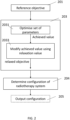
- the step of determining a configuration of the radiotherapy system is based on at least a set of optimised parameters and a relaxed objective from stage one (step 151).
- the relaxed objective(s) may be used in the formulation of the optimisation problem of step 153.
- the optimisation problem of step 153 may be improved (e.g., by having improved convergence, or improving the chance that the outcome of step 153 is suitable)
- Fig. 1B relates to one specific angle.
- a prior step would be to determine the angles from which radiation is to be delivered from.
- the beam angle optimisation (BAO) procedure is carried out before the procedure of Fig. 1B .
- the procedure of Fig. 1B is then carried out for each determined angle.
- BAO beam angle optimisation
- Fig. 1B relates a two-stage optimisation procedure (FMO at step 151 and determination of a configuration at step 153) for IMRT
- alternative methods of optimisation such as Direct Machine Parameter Optimisation (DMPO)
- DMPO Direct Machine Parameter Optimisation
- the decision variable x corresponds to a parameter of a machine (e.g. an MLC leaf position) that delivers radiation.
- the decision variable x may correspond to any one or more of the following: number of beams, beam angles, a dose per beam, beamlet weights, segment or control point shapes, segment or control point weights, dose-volume histogram information, a dose excess value.
- cost function 102 in optimisation procedure 100, examples of cost functions comprise: Target EUD, Target Penalty, Quadratic Overdose, Quadratic Underdose, Serial, Parallel, Maximum Dose, Overdose DVH, Underdose DVH.
- the cost functions are briefly defined below. Each cost function offers different calculation methods.
- the reference objective is a dose value and a relative volume component (e.g. a percentage) or an absolute volume (e.g. in cc).
- the reference objective is a dose value.
- Cost functions such as serial, parallel, quadratic overdose, overdose DVH, or maximum dose aim to limit the dose at an anatomical structure. For example, for these cost functions, a penalty is increased as the achieved dose exceeds a reference dose. The penalty may increase the further the achieved dose is above the reference dose.
- Cost functions such as quadratic underdose or underdose DVH aim to increase the dose at an anatomical structure.
- Cost functions such as Target EUD and Target Penalty aim to increase the dose at a structure. For example, these cost functions are used for target or PTV.
- a penalty increases when the achieved dose is lower than a reference dose. The penalty may increase the further the achieved dose is below the reference dose.
- the unitless number (k) is a power law exponent.
- the Target EUD cost function defines a structure as a target volume and expresses the probability that a target cell survives a given dose.
- This cost function requires a prescribed dose as input (i.e. the reference objective for this cost function is a dose value).
- the prescribed dose, in Gy is an equivalent uniform dose (EUD).
- EUD is a homogenous dose that, if delivered at an anatomical structure, has the same clinical effect that a non-homogenous dose distribution would.
- the Target Penalty cost function takes as input a prescribed dose and a minimum volume as input (i.e., the reference objective for this cost function is a dose and a relative volume).
- the Target Penalty is a quadratic penalty which starts at a threshold dose. It produces steeper dose gradients after a target threshold is met.
- the Target Penalty is used to define the requirement that at least some fraction of the total anatomical structure volume should receive at least the target dose.
- the quadratic overdose (QO) cost function is a cost function used to limit the dose in the structure to which it is applied.
- the QO may be applied to either targets or OARs.
- the QO cost function may be used to limit hot spots in a target.
- the QO cost function takes as input a maximum dose and a root-mean square (RMS) dose excess (i.e. the reference objectives comprises two dose values).
- the maximum dose defines a dose beyond which a penalty is incurred.
- the RMS dose excess defines the amount of violation that is acceptable.
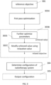
- the second pass relaxation value is smaller than the first pass relaxation value. This may improve the optimisation procedure further.
- the optimiser has already covered a broad solution space.
- the second pass optimisation step 303B the smaller relaxation parameter narrows the solution space and leads to improved optimisation.
- the second relaxation value is between 25% to 75% of the first relaxation value. Further optionally, the second relaxation value is 50% of the first relaxation value.
- the first pass and/or second pass relaxation value is defined relative to (e.g. as a ratio of or a percentage (%) of) a reference objective (which may comprise a dose value) or relative to an achieved value.
- a relaxation value is 3%.
- values for the relaxation include 2%, 5% or 10%.
- the relaxation value is a ratio or percentage, the relaxation may be bounded by a lower value and an upper value. The upper value may be different from the lower value.
- the relaxation value is 3% (of an achieved value) with 0.6 Gy as lower bound, and 1.2Gy as upper bound.
- the lower value and upper value for the second pass optimisation may differ from the lower value and upper value for the first pass optimisation (step 303A).
- the purpose of the lower bound and upper bound is to enable the relaxed objective to lie in a more suitable range.
- one reference objective is received (step 201 or step 301). However, additionally and optionally, a plurality of reference objectives is received. Each reference objective is tackled in turn.
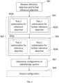
- Fig. 4 shows a flow chart of a method of radiotherapy treatment planning according to an embodiment.
- the method is for delivering radiation therapy by a radiotherapy system (such as the radiotherapy system 600 of Fig. 7 ).
- the method of Fig. 4 may be performed by the treatment planning system 610 described in relation to Fig. 7 .
- Step 901 is analogous to step 201 or 301 except that a first and a second reference objective are received.
- the first reference objective may be referred to as a reference objective
- the second reference objective may be referred to as a further reference objective.
- Step 903 may be referred to as first pass optimisation and step 905 may be referred to as second pass optimisation.
- Step 903 each received objective is taken in turn and first pass optimisation (pass 1 optimisation) is performed for each.
- Step 903 comprises step 903A, where first pass optimisation based on the first reference objective is performed, and step 903B, where first pass optimisation based on the second reference objective is performed.
- step 903A The aim of step 903A is to determine parameters that would achieve the first reference objective received in step 901.
- Step 903A is corresponds to step 203 or 303A.
- step 903A comprises the following steps.
- Step 903A After first pass optimisation based on the first objective is performed (step 903A), a further first pass optimisation based on the second reference objective is performed (Step 903B).
- the aim of step 903B is to determine parameters that would achieve the second reference objective received in step 901.
- Step 903B corresponds to step 203 or 303A.
- step 903B comprises the following steps.
- the outputs of step 903 may be considered to be the set of optimised parameters obtained in step 903B.
- the outputs may also include any one or more of the first pass relaxed objective from step 903A, and the further first pass relaxed objective of step 903B.
- step 903 second pass optimisation is performed at step 905.
- Step 905 comprises step 905A, where second pass optimisation based on the first reference objective is performed, and step 905B, where second pass optimisation based on the second reference objective is performed. Note that steps 905A and 905B may be skipped in some circumstances (indicated by dashed lines in Fig. 4 ), as described herein.
- step 905A The aim of step 905A is to determine parameters that would achieve the first reference objective received in step 901, starting from the set of optimised parameters obtained from step 903.
- Step 905A corresponds to step 303B.
- step 905A comprises the following steps.
- Step 905B After second pass optimisation based on the first objective is performed (step 905A), a further second pass optimisation based on the second reference objective is performed (Step 905B).
- the aim of step 905B is to determine parameters that would achieve the second reference objective received in step 901. Step 905B corresponds to step 303B.
- step 905B comprises the following steps.
- the outputs of step 905 may be considered to be the set of optimised parameters obtained in step 905A or 905B (if step 905B has been performed).
- the outputs may also include any one or more of the second pass relaxed objective from step 905A, and the further second pass relaxed objective of step 905B.
- Steps 903 and 905 collectively correspond to a fluence map optimisation step 902.
- Step 902 corresponds to step 151 of Fig. 1B .
- step 905 a set of optimised parameters from the second pass optimisation (step 905), and either of:
- a configuration of the radiotherapy system is determined, based on the set optimised parameters and relaxed objectives from step 902.
- Step 907 corresponds to step 153 of Fig. 1B .
- the configuration obtained in step 907 is outputted for use by a radiotherapy system.
- Step 909 is optional.
- the first and/or second relaxation value is based on the cost function
- the first pass relaxation value used in step 903A may be different from the first pass relaxation value used in step 903B.
- the second pass relaxation value used in step 905A may be different from the second pass relaxation value used in step 905B.
- Fig. 4 comprises a first and a second objective
- the method of Fig. 4 is applicable to three or more reference objectives.
- objectives may be prioritised and each objective is taken in turn based on its priority.
- the objectives may be:
- the wish-list shown in Table 1 comprises the following.
- the wish-list comprises the 'clinical' constraints (rows a to f). The violation of those constraints implies plan rejection.
- the wish-list further comprises 'planning' constraints (rows g to l). The purpose of 'planning' constraints is to achieve dose conformality and control of potential hotspots.
- the clinical constraints and planning constraints are pre-defined constraints.
- step 407 of Fig. 4 may refer to checking whether such clinical constraints are met.
- the purpose of constraints in rows a to I is to limit the dose at the corresponding structures.
- the wish-list further comprises prioritised objectives (row m to x).
- the prioritised objectives each correspond to the reference objective described herein.
- the prioritized objectives comprise: objectives that relate to the dose coverage and conformality of the target (which are the 1st-priority objectives in rows m to q), and objectives that are concerned with dose sparing of the OARs (rows r to y).
- the prioritised objective may be user-defined priorities.
- the "Cost function (parameter values)" relates to the type of cost function to be used. For some cost functions, additional parameters are provided.
- the 'Goal' refers to a dose or volume to be achieved by the treatment planning system.
- cost functions and associated goals each achieving different purposes. For example, at rows r to t, for the 'Rectum' structure, different cost functions and goals are applied.
- the priority refers to the relative priority of the reference objectives.
- the objectives that relate to dose coverage and conformality of the target (which are the 1st-priority objectives in rows m to q) are optimised first, and objectives that are concerned with dose sparing of the OARs (rows r to y) are optimised after, in order of their priorities.
- the layering order relates to structure volumes that overlap.
- structures comprise overlapping voxels
- Fig. 5 shows a flow chart of an optimisation procedure for radiotherapy treatment planning according to an embodiment.
- the method is for delivering radiation therapy by a radiotherapy system (such as the radiotherapy system 600 of Fig. 7 ).
- the method of Fig. 5 may be performed by the treatment planning system 610 described in relation to Fig. 7 .
- the optimisation is started.
- step 403 the contribution of each beamlet, at unit fluence, to voxels is calculated.
- first pass optimisation (pass 1 optimisation) is performed.
- one or more objectives may be obtained.
- the objectives are prioritised and each objective is considered in turn based on its priority.
- an objective represents a clinical goal to be achieved.
- An objective may be referred to as a treatment-planning objective.
- Step 404 comprises steps 405, 407, 409, 411, 413, 415, 417, 419 and 421.
- step 411 it is checked whether the first priority objective met its clinical goal. In other words, it is checked whether the achieved value after optimisation at step 407 meets the first priority objective (reference objective).
- a constraint is set to the goal value (i.e. the reference objective).
- the constraint is intended to be used in subsequent steps.
- subsequent steps comprise first pass optimisation of another objective, second pass of optimisation of the same prioritised objective, or a step subsequent to the optimisation procedure.
- the second pass is described below in relation to Fig. 6 .
- the purpose of step 413 is to leave room in the solution space for subsequent optimisation.
- steps 405 to 417 are repeated for all objectives.
- a first optimisation pass (steps 405 to 417) is carried out and an achieved value is obtained.
- a constraint is obtained. The constraint is set to the goal (reference objective) if the achieved value meets the reference objective(step 413), or to a relaxed value (if goal could not be met)(step 415).
- the cost function will be revisited in the second pass of the optimization.
- step 421 the first optimisation pass is completed, and the procedure moves to the second optimisation pass described in relation to Fig. 6
- Fig. 6 shows a flow chart of an optimisation procedure for radiotherapy treatment planning according to an embodiment.
- the method shown in Fig. 6 follows the steps carried out in the method of Fig. 5 .
- the flow chart of Fig. 6 depicts second pass optimisation.
- the method is for delivering radiation therapy by a radiotherapy system (such as the radiotherapy system 600 of Fig. 7 ).
- the method of Fig. 6 may be performed by the treatment planning system 610 described in relation to Fig. 7 .
- Step 502 comprises steps 503 to 521.
- step 503 it is checked whether the first priority objective meets the achieved goal from the first pass. In other words, it is checked whether the achieved value obtained after optimisation at step 405 of Fig. 5 meets the first priority objective (reference objective). When the first priority objective does not meet the achieved goal from the first pass, no further optimisation is carried out for this priority objective.
- the constraint is kept at its current value at step 505. The constraint is used in subsequent steps. The procedure then moves to the next objective at step 521.
- step 503 when the first priority objective meets the achieved goal from the first pass, the method progresses to step 507.
- step 507 it is checked whether a sufficient value exists.
- the sufficient value is a pre-determined condition. If the sufficient value exists, the method progresses to step 509, and, if not, to step 517.
- a sufficient value is a value that is considered to be good enough from a clinical standpoint. For example, it is desired to spare the parotid, by reducing the mean dose to the parotid gland.
- the complication probability at the 10 Gy level is very low. This means that trying to reduce the dose to the parotid gland from 10 Gy to 5 Gy may be at the cost of plan complexity (and lead to potential issues with plan QA), and may lead to increased treatment delivery times without any clinical benefit to the patient.
- the optimizer is stopped from pushing down further (i.e. the optimiser is prevented from computation once a good enough achieved objective is obtained).
- step 509 further optimisation is performed until the first priority objective (i.e. the achieved value after optimisation) meets or betters the sufficient value.
- the first priority objective is pushed (i.e. optimisation is performed) as low as possible but stopped at the sufficient value.
- step 511 it is checked if the sufficient value has been reached. If so, at step 513, the sufficient value is used as a constraint (instead of the goal). The constraint is used in subsequent steps.
- the constraint is set to the achieved value relaxed by a second relaxation value.
- a second relaxation value is applied to the achieved value to obtain a second relaxed objective, and said second relaxed objective is used as a constraint in subsequent steps. The method then progresses to step 521.
- steps 503, 507, 509, 511, 513, and 515 is to revisit the achieved objective value from the first optimisation pass (the achieved objective value having met the reference objective from the first pass) such that the achieved objective value reaches the sufficient value or its lowest possible value (i.e. the achieved objective value is made more suitable for a relaxation value to be applied to obtain a more suitable second relaxed objective value).
- step 507 the method progresses to step 517 when a sufficient value does not exist.
- step 517 further optimisation is performed such that first priority objective reaches an optimum (i.e. the achieved value obtained after optimisation is pushed as low as possible).
- the purpose of steps 503, 507, 517, and 519 is to revisit the achieved objective value from the first optimisation pass (the achieved objective value having met the reference objective from the first pass) such that the achieved objective value reaches its lowest possible value (step 517) (i.e. the achieved objective value is made more suitable for a relaxation value to be applied to obtain a more suitable second relaxed objective value).
- the constraint is set to the achieved objective value from step 517, relaxed by the second relaxation value.
- a second relaxation value is applied to the achieved objective value to obtain a second relaxed objective.
- the second relaxed objective is used as a constraint in a subsequent steps. The method then progresses to step 521, where the next objective is considered.
- steps 503 to 521 are repeated for all objectives.
- a second optimisation pass is carried out and a second pass constraint for a subsequent step is obtained.
- step 525 second pass optimisation is completed.
- Fig. 7 illustrates a block diagram of an implementation of a radiotherapy system 600.
- the radiotherapy system 600 comprises a computing system 610 within which a set of instructions, for causing the computing system 610 to perform any one or more of the methods discussed herein, may be executed.
- the computing system 610 may implement a treatment planning system.
- the computing system 610 may also be referred to as a computer.
- the treatment planning system 610 may perform any of the methods described herein. In particular, the methods described herein may be implemented by a processor 611 of the treatment planning system 610.
- the computing system 610 shall be taken to include any number or collection of machines, e.g. computing device(s), that individually or jointly execute a set (or multiple sets) of instructions to perform any one or more of the methods discussed herein. That is, hardware and/or software may be provided in a single computing device, or distributed across a plurality of computing devices in the computing system. In some implementations, one or more elements of the computing system may be connected (e.g., networked) to other machines, for example in a Local Area Network (LAN), an intranet, an extranet, or the Internet.
- LAN Local Area Network
- One or more elements of the computing system may operate in the capacity of a server or a client machine in a client-server network environment, or as a peer machine in a peer-to-peer (or distributed) network environment.
- One or more elements of the computing system may be a personal computer (PC), a tablet computer, a set-top box (STB), a Personal Digital Assistant (PDA), a cellular telephone, a web appliance, a server, a network router, switch or bridge, or any machine capable of executing a set of instructions (sequential or otherwise) that specify actions to be taken by that machine.
- PC personal computer
- PDA Personal Digital Assistant
- the computing system 610 includes controller circuitry 611 and a memory 613 (e.g., read-only memory (ROM), flash memory, dynamic random access memory (DRAM) such as synchronous DRAM (SDRAM) or Rambus DRAM (RDRAM), etc.).
- the memory 613 may comprise a static memory (e.g., flash memory, static random access memory (SRAM), etc.), and/or a secondary memory (e.g., a data storage device), which communicate with each other via a bus (not shown).
- Controller circuitry 611 represents one or more general-purpose processors such as a microprocessor, central processing unit, accelerated processing units, or the like. More particularly, the controller circuitry 611 may comprise a complex instruction set computing (CISC) microprocessor, reduced instruction set computing (RISC) microprocessor, very long instruction word (VLIW) microprocessor, processor implementing other instruction sets, or processors implementing a combination of instruction sets. Controller circuitry 611 may also include one or more special-purpose processing devices such as an application specific integrated circuit (ASIC), a field programmable gate array (FPGA), a digital signal processor (DSP), network processor, or the like. One or more processors of the controller circuitry may have a multicore design. Controller circuitry 611 is configured to execute the processing logic for performing the operations and steps discussed herein.
- CISC complex instruction set computing
- RISC reduced instruction set computing
- VLIW very long instruction word
- Controller circuitry 611 may also include one or more special-purpose processing devices such as an application specific integrated circuit (ASIC
- the computing system 610 may further include a network interface circuitry 618.
- the computing system 610 may be communicatively coupled to an input device 620 and/or an output device 630, via input/output circuitry 617.
- the input device 620 and/or the output device 630 may be elements of the computing system 610.
- the input device 620 may include an alphanumeric input device (e.g., a keyboard or touchscreen), a cursor control device (e.g., a mouse or touchscreen), an audio device such as a microphone, and/or a haptic input device.
- the output device 630 may include an audio device such as a speaker, a video display unit (e.g., a liquid crystal display (LCD) or a cathode ray tube (CRT)), and/or a haptic output device.
- a video display unit e.g., a liquid crystal display (LCD) or a cathode ray tube (CRT)
- a haptic output device e.g., a speaker, a speaker, a video display unit (e.g., a liquid crystal display (LCD) or a cathode ray tube (CRT)), and/or a haptic output device.
- the input device 620 and the output device 630 may be provided as a single device, or as separate devices.
- the computing system 610 may comprise image processing circuitry 619.
- Image processing circuitry 619 may be configured to process image data 680 (e.g. images, or imaging data), such as medical images obtained from one or more imaging data sources, a treatment device 650 and/or an image acquisition device 640.
- Image processing circuitry 619 may be configured to process, or pre-process, image data.
- image processing circuitry 619 may convert received image data into a particular format, size, resolution or the like.
- image processing circuitry 619 may be combined with controller circuitry 611.
- the radiotherapy system 600 may further comprise an image acquisition device 640 and/or a treatment device 650, such as those disclosed herein in the examples of Fig. 8 .
- the image acquisition device 640 and the treatment device 650 may be provided as a single device.
- treatment device 650 is configured to perform imaging, for example in addition to providing treatment and/or during treatment.
- the treatment device 650 comprises the main radiation delivery components of the radiotherapy system, such as beam shaping apparatus 850.
- Image acquisition device 640 may be configured to perform positron emission tomography (PET), computed tomography (CT), magnetic resonance imaging (MRI), single positron emission computed tomography (SPECT), x-ray, and the like.
- PET positron emission tomography
- CT computed tomography
- MRI magnetic resonance imaging
- SPECT single positron emission computed tomography
- x-ray x-ray
- Image acquisition device 640 may be configured to output image data 680, which may be accessed by computing system 610.
- Treatment device 650 may be configured to output treatment data 660, which may be accessed by computing system 610.
- Computing system 610 may be configured to access or obtain treatment data 660, planning data 670 and/or image data 680.
- Treatment data 660 may be obtained from an internal data source (e.g. from memory 613) or from an external data source, such as treatment device 650 or an external database.
- Planning data 670 may be obtained from memory 613 and/or from an external source, such as a planning database. Planning data 670 may comprise information obtained from one or more of the image acquisition device 640 and the treatment device 650.
- the various methods described above may be implemented by a computer program.
- the computer program may include computer code (e.g. instructions) 710 arranged to instruct a computer to perform the functions of one or more of the various methods described above.
- the steps of the methods described in relation to Fig. 2 , Fig. 3 , Fig. 4 , Fig. 5 and Fig. 6 may be performed by the computer code 710.
- the steps of the methods described above may be performed in any suitable order.
- the computer program and/or the code 710 for performing such methods may be provided to an apparatus, such as a computer, on one or more computer readable media or, more generally, a computer program product 700)), depicted in Fig. 8 .
- the computer readable media may be transitory or non-transitory.
- the one or more computer readable media 700 could be, for example, an electronic, magnetic, optical, electromagnetic, infrared, or semiconductor system, or a propagation medium for data transmission, for example for downloading the code over the Internet.
- the one or more computer readable media could take the form of one or more physical computer readable media such as semiconductor or solid state memory, magnetic tape, a removable computer diskette, a random access memory (RAM), a read-only memory (ROM), a rigid magnetic disc, and an optical disk, such as a CD-ROM, CD-R/W or DVD.
- the instructions 710 may also reside, completely or at least partially, within the memory 613 and/or within the controller circuitry 611 during execution thereof by the computing system 610, the memory 613 and the controller circuitry 611 also constituting computer-readable storage media.
- modules, components and other features described herein can be implemented as discrete components or integrated in the functionality of hardware components such as ASICS, FPGAs, DSPs or similar devices.
- a “hardware component” is a tangible (e.g., non-transitory) physical component (e.g., a set of one or more processors) capable of performing certain operations and may be configured or arranged in a certain physical manner.
- a hardware component may include dedicated circuitry or logic that is permanently configured to perform certain operations.
- a hardware component may comprise a special-purpose processor, such as an FPGA or an ASIC.
- a hardware component may also include programmable logic or circuitry that is temporarily configured by software to perform certain operations.
- modules and components can be implemented as firmware or functional circuitry within hardware devices. Further, the modules and components can be implemented in any combination of hardware devices and software components, or only in software (e.g., code stored or otherwise embodied in a machine-readable medium or in a transmission medium).
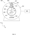
- Fig. 9 depicts a radiotherapy apparatus according to the present disclosure.
- Fig. 9 shows a cross-section through a radiotherapy apparatus 800 comprising a radiation head 804 and a beam receiving apparatus 806, both of which are attached to a gantry 802.
- the radiation head 804 includes a radiation source 807 which emits a beam of radiation 822.
- the radiation head 804 also includes a beam shaping apparatus 850 which controls the size and shape of the radiation field associated with the beam.
- the beam receiving apparatus 806 is configured to receive radiation emitted from the radiation head 804, for the purpose of absorbing and/or measuring the beam of radiation.
- the radiation head 804 and the beam receiving apparatus 806 are positioned diametrically opposed to one another.
- the gantry 802 is rotatable, and supports the radiation head 804 and the beam receiving apparatus 806 such that they are rotatable around an axis of rotation 805, which may coincide with the patient longitudinal axis.
- the gantry provides rotation of the radiation head 804 and the beam receiving apparatus 806 in a plane which is perpendicular to the patient longitudinal axis (e.g. a sagittal plane).
- Three gantry directions XG, YG, ZG can be defined, where the YG direction is perpendicular with gantry axis of rotation.
- the ZG direction extends from a point on the gantry corresponding to the radiation head, towards the axis of rotation of the gantry. Therefore, from the patient frame of reference, the ZG direction rotates around as the gantry rotates.
- Fig. 9 also shows a support surface 810 on which a subject (or patient) is supported during radiotherapy treatment.
- the radiation head 804 is configured to rotate around the axis of rotation 805 such that the radiation head 804 directs radiation towards the subject from various angles around the subject in order to spread out the radiation dose received by healthy tissue to a larger region of healthy tissue while building up a prescribed dose of radiation at a target region.
- the radiotherapy apparatus 800 is configured to deliver a radiation beam towards a radiation isocentre which is substantially located on the axis of rotation 805 at the centre of the gantry 802 regardless of the angle at which the radiation head 804 is placed.
- the rotatable gantry 802 and radiation head 804 are dimensioned so as to allow a central bore 880 to exist.
- the central bore 880 provides opening sufficient to allow a subject to be positioned therethrough without the possibility of being incidentally contacted by the radiation head 804 or other mechanical components as the gantry rotates the radiation head 804 about the subject.
- the radiation head 804 emits the radiation beam 822 along a beam axis 890 (or radiation axis or beam path), where the beam axis 890 is used to define the direction in which the radiation is emitted by the radiation head.
- the radiation beam 822 is incident on the beam receiving apparatus 806 which can include at least one of a beam stopper and a radiation detector.
- the beam receiving apparatus 806 is attached to the gantry 802 on a diametrically opposite side to the radiation head 804 to attenuate and/or detect a beam of radiation after the beam has passed through the subject.
- the radiation beam axis 890 may be defined as, for example, a centre of the radiation beam 822 or a point of maximum intensity.
- the beam shaping apparatus 850 delimits the spread of the radiation beam 822.
- the beam shaping apparatus 850 is configured to adjust the shape and/or size of a field of radiation produced by the radiation source.
- the beam shaping apparatus 850 does this by defining an aperture (also referred to as a window or an opening) of variable shape to collimate the radiation beam 822 to a chosen cross-sectional shape.
- the beam shaping apparatus 850 may be provided by a combination of a diaphragm and a multi-leaf collimator (MLC).
- MLC multi-leaf collimator
- Beam shaping apparatus 850 may also be referred to as a bean modifier.
- the radiotherapy apparatus 800 may be configured to deliver both coplanar and non-coplanar (also referred to as tilted) modes of radiotherapy treatment.
- coplanar treatment radiation is emitted in a plane which is perpendicular to the axis of rotation of the radiation head 804.
- non-coplanar treatment radiation is emitted at an angle which is not perpendicular to the axis of rotation.
- the radiation head 804 can move between at least two positions, one in which the radiation is emitted in a plane which is perpendicular to the axis of rotation (coplanar configuration) and one in which radiation is emitted in a plane which is not perpendicular to the axis of rotation (non-coplanar configuration).
- the radiation head In the coplanar configuration, the radiation head is positioned to rotate about a rotation axis and in a first plane. In the non-coplanar configuration, the radiation head is tilted with respect to the first plane such that a field of radiation produced by the radiation head is directed at an oblique angle relative to the first plane and the rotation axis. In the non-coplanar configuration, the radiation head is positioned to rotate in a respective second plane parallel to and displaced from the first plane. The radiation beam is emitted at an oblique angle with respect to the second plane, and therefore as the radiation head rotates the beam sweeps out a cone shape.
- the beam receiving apparatus 806 remains in the same place relative to the rotatable gantry when the radiotherapy apparatus is in both the coplanar and non-coplanar modes. Therefore, the beam receiving apparatus 806 is configured to rotate about the rotation axis in the same plane in both coplanar and non-coplanar modes. This may be the same plane as the plane in which the radiation head rotates.
- the beam shaping apparatus 850 is configured to reduce the spread of the field of radiation in the non-coplanar configuration in comparison to the coplanar configuration.
- the radiotherapy apparatus 800 includes a controller 840 which is programmed to control the radiation source 807, beam receiving apparatus 806 and the gantry 802. Controller 840 may perform functions or operations such as treatment planning, treatment execution, image acquisition, image processing, motion tracking, motion management, and/or other tasks involved in a radiotherapy process.
- Controller 840 is programmed to control features of apparatus 800 according to a radiotherapy treatment plan for irradiating a target region, also referred to as a target tissue, of a patient.
- the treatment plan includes information about a particular dose to be applied to a target tissue, as well as other parameters such as beam angles, dose-histogram-volume information, the number of radiation beams to be used during therapy, the dose per beam, and the like.
- Controller 840 is programmed to control various components of apparatus 800, such as gantry 802, radiation head 804, beam receiving apparatus 806, and support surface 810, according to the treatment plan.
- Hardware components of controller 840 may include one or more computers (e.g., general purpose computers, workstations, servers, terminals, portable/mobile devices, etc.); processors (e.g., central processing units (CPUs), graphics processing units (GPUs), microprocessors, digital signal processors (DSPs), field programmable gate arrays (FPGAs), special-purpose or specially-designed processors, etc.); memory/storage devices such as a memory (e.g., read-only memories (ROMs), random access memories (RAMs), flash memories, hard drives, optical disks, solid-state drives (SSDs), etc.); input devices (e.g., keyboards, mice, touch screens, mics, buttons, knobs, trackballs, levers, handles, joysticks, etc.); output devices (e.g., displays, printers, speakers, vibration devices, etc.); circuitries; printed circuit boards (PCBs); or other suitable hardware.
- Software components of controller 140 may include operation device software, application software, etc.
- the radiation head 804 may be connected to a head actuator 830 which is configured to actuate the radiation head 804, for example between a coplanar configuration and one or more non-coplanar configurations. This may involve translation and rotation of the radiation head 804 relative to the gantry.
- the head actuator may include a curved rail along which the radiation head 804 may be moved to adjust the position and angle of the radiation head 804.
- the controller 840 may control the configuration of the radiation head 804 via the head actuator 830.
- the beam shaping apparatus 850 includes a shaping actuator 832.
- the shaping actuator is configured to control the position of one or more elements in the beam shaping apparatus 850 in order to shape the radiation beam 822.
- the beam shaping apparatus 850 includes an MLC, and the shaping actuator 832 includes means for actuating leaves of the MLC.
- the beam shaping apparatus 850 may further comprise a diaphragm, and the shaping actuator 832 may include means for actuating blocks of the diaphragm.
- the controller 840 may control the beam shaping apparatus 850 via the shaping actuator 832.
- a treatment plan may comprise positioning information of beam shaping apparatus 850.
- the positioning information of beam shaping apparatus 850 may comprise information indicating a configuration of one or more elements of beam shaping apparatus 850, such as leaf configuration of an MLC of beam shaping apparatus 850, a configuration of a diaphragm of beam shaping apparatus 850, a configuration of an opening (e.g., window or aperture) of the MLC, and/or the like.
- an optimiser or of an optimisation procedure
- the purpose of an optimisation procedure is to find a set of optimised parameters for which a cost function is minimised.
Landscapes
- Health & Medical Sciences (AREA)
- Engineering & Computer Science (AREA)
- Biomedical Technology (AREA)
- General Health & Medical Sciences (AREA)
- Public Health (AREA)
- Nuclear Medicine, Radiotherapy & Molecular Imaging (AREA)
- Veterinary Medicine (AREA)
- Animal Behavior & Ethology (AREA)
- Pathology (AREA)
- Life Sciences & Earth Sciences (AREA)
- Radiology & Medical Imaging (AREA)
- Surgery (AREA)
- Urology & Nephrology (AREA)
- Epidemiology (AREA)
- Medical Informatics (AREA)
- Primary Health Care (AREA)
- Radiation-Therapy Devices (AREA)
Applications Claiming Priority (1)
| Application Number | Priority Date | Filing Date | Title |
|---|---|---|---|
| US18/315,961 US12582840B2 (en) | 2023-05-11 | 2023-05-11 | System and method for radiation treatment planning |
Publications (1)
| Publication Number | Publication Date |
|---|---|
| EP4487906A1 true EP4487906A1 (de) | 2025-01-08 |
Family
ID=91076739
Family Applications (1)
| Application Number | Title | Priority Date | Filing Date |
|---|---|---|---|
| EP24175404.3A Pending EP4487906A1 (de) | 2023-05-11 | 2024-05-13 | System und verfahren zur planung einer strahlenbehandlung |
Country Status (3)
| Country | Link |
|---|---|
| US (1) | US12582840B2 (de) |
| EP (1) | EP4487906A1 (de) |
| CN (1) | CN118925083A (de) |
Citations (4)
| Publication number | Priority date | Publication date | Assignee | Title |
|---|---|---|---|---|
| US20100104068A1 (en) * | 2008-10-23 | 2010-04-29 | Kilby Warren D | Sequential optimizations for treatment planning |
| US20130072742A1 (en) * | 2011-09-20 | 2013-03-21 | Janne Nord | Method and apparatus pertaining to multi-stage radiation-treatment plan optimization |
| US20190247676A1 (en) * | 2018-02-13 | 2019-08-15 | Varian Medical Systems International Ag | Optimizing radiation dose to overlapping structures |
| EP3681600A1 (de) | 2017-09-13 | 2020-07-22 | Elekta, Inc. | Optimierung des arbeitsablaufs für strahlentherapiebehandlungspläne |
Family Cites Families (11)
| Publication number | Priority date | Publication date | Assignee | Title |
|---|---|---|---|---|
| US6064203A (en) | 1997-05-20 | 2000-05-16 | The Johns Hopkins University | Method and apparatus for determining or imaging longitudinal spin relaxation time or producing images which substantially reflect longitudinal spin relaxation time contrast |
| US6402689B1 (en) | 1998-09-30 | 2002-06-11 | Sicel Technologies, Inc. | Methods, systems, and associated implantable devices for dynamic monitoring of physiological and biological properties of tumors |
| CN101006541B (zh) | 2003-06-02 | 2010-07-07 | 福克斯·彻斯癌症中心 | 高能多能离子选择系统、离子束治疗系统及离子束治疗中心 |
| US8492735B2 (en) | 2010-05-27 | 2013-07-23 | Mitsubishi Electric Research Laboratories, Inc. | Method for optimization radiotherapy particle beams |
| CN107072595B (zh) | 2013-12-31 | 2021-11-26 | 威斯康星州医药大学股份有限公司 | 基于多模态成像的自适应重计划 |
| US20150202464A1 (en) | 2014-01-23 | 2015-07-23 | Mitsubis | Multi-Criteria Optimization in Particle Beam Dose Optimization |
| US9884206B2 (en) | 2015-07-23 | 2018-02-06 | Loma Linda University Medical Center | Systems and methods for intensity modulated radiation therapy |
| US10737114B2 (en) | 2016-12-06 | 2020-08-11 | International Business Machines Corporation | Translating different clinical protocols for particle therapy into a set of constraints |
| US10512791B2 (en) | 2018-02-06 | 2019-12-24 | Varian Medical Systems International Ag | Methods to optimize coverage for multiple targets simultaneously for radiation treatments |
| US12036422B2 (en) | 2019-11-11 | 2024-07-16 | Siemens Healthineers International Ag | Expansion of search space for multicriteria optimization in radiation treatment planning |
| US12186585B2 (en) | 2020-04-09 | 2025-01-07 | Accenture Global Solutions Limited | Quantum computation for intensity-modulated radiation therapy |
-
2023
- 2023-05-11 US US18/315,961 patent/US12582840B2/en active Active
-
2024
- 2024-05-10 CN CN202410577602.7A patent/CN118925083A/zh active Pending
- 2024-05-13 EP EP24175404.3A patent/EP4487906A1/de active Pending
Patent Citations (4)
| Publication number | Priority date | Publication date | Assignee | Title |
|---|---|---|---|---|
| US20100104068A1 (en) * | 2008-10-23 | 2010-04-29 | Kilby Warren D | Sequential optimizations for treatment planning |
| US20130072742A1 (en) * | 2011-09-20 | 2013-03-21 | Janne Nord | Method and apparatus pertaining to multi-stage radiation-treatment plan optimization |
| EP3681600A1 (de) | 2017-09-13 | 2020-07-22 | Elekta, Inc. | Optimierung des arbeitsablaufs für strahlentherapiebehandlungspläne |
| US20190247676A1 (en) * | 2018-02-13 | 2019-08-15 | Varian Medical Systems International Ag | Optimizing radiation dose to overlapping structures |
Also Published As
| Publication number | Publication date |
|---|---|
| US20240374925A1 (en) | 2024-11-14 |
| CN118925083A (zh) | 2024-11-12 |
| US12582840B2 (en) | 2026-03-24 |
Similar Documents
| Publication | Publication Date | Title |
|---|---|---|
| US10857384B2 (en) | Controlling and shaping the dose distribution outside treatment targets in external-beam radiation treatments | |
| EP3655098B1 (de) | Geometrische aspekte einer strahlentherapieplanung und -behandlung | |
| CN110960805B (zh) | 对强度调制质子疗法执行照射时间优化的方法和装置 | |
| US11103726B2 (en) | Creating treatment field using initial field and patient specific geometry and achievable dose | |
| US7801270B2 (en) | Treatment plan optimization method for radiation therapy | |
| US10835760B2 (en) | Methods to optimize coverage for multiple targets simultaneously for radiation treatments | |
| EP4461350A1 (de) | Verfahren und system zur behandlungsplanung | |
| EP4292648B1 (de) | Punktpositionierung auf basis der minimalen überwachungseinheitseinschränkung und optimierungsziele für ein strahlentherapiesystem | |
| US20260102632A1 (en) | System and method for radiation treatment planning | |
| EP4487907A1 (de) | Verfahren und system zur planung einer strahlenbehandlung | |
| EP4461351A1 (de) | Verfahren und system zur behandlungsplanung | |
| EP4487906A1 (de) | System und verfahren zur planung einer strahlenbehandlung | |
| WO2025147994A1 (en) | System and method for radiation treatment planning | |
| US20250360337A1 (en) | Dose adjustment for maximum field delivery time in radiation therapy treatment planning |
Legal Events
| Date | Code | Title | Description |
|---|---|---|---|
| PUAI | Public reference made under article 153(3) epc to a published international application that has entered the european phase |
Free format text: ORIGINAL CODE: 0009012 |
|
| STAA | Information on the status of an ep patent application or granted ep patent |
Free format text: STATUS: THE APPLICATION HAS BEEN PUBLISHED |
|
| AK | Designated contracting states |
Kind code of ref document: A1 Designated state(s): AL AT BE BG CH CY CZ DE DK EE ES FI FR GB GR HR HU IE IS IT LI LT LU LV MC ME MK MT NL NO PL PT RO RS SE SI SK SM TR |
|
| STAA | Information on the status of an ep patent application or granted ep patent |
Free format text: STATUS: REQUEST FOR EXAMINATION WAS MADE |
|
| 17P | Request for examination filed |
Effective date: 20250708 |