EP4487895A1 - Catheter assembly - Google Patents
Catheter assembly Download PDFInfo
- Publication number
- EP4487895A1 EP4487895A1 EP23774469.3A EP23774469A EP4487895A1 EP 4487895 A1 EP4487895 A1 EP 4487895A1 EP 23774469 A EP23774469 A EP 23774469A EP 4487895 A1 EP4487895 A1 EP 4487895A1
- Authority
- EP
- European Patent Office
- Prior art keywords
- catheter
- needle
- fitting portion
- fitting
- connection portion
- Prior art date
- Legal status (The legal status is an assumption and is not a legal conclusion. Google has not performed a legal analysis and makes no representation as to the accuracy of the status listed.)
- Pending
Links
Images







Classifications
-
- A—HUMAN NECESSITIES
- A61—MEDICAL OR VETERINARY SCIENCE; HYGIENE
- A61M—DEVICES FOR INTRODUCING MEDIA INTO, OR ONTO, THE BODY; DEVICES FOR TRANSDUCING BODY MEDIA OR FOR TAKING MEDIA FROM THE BODY; DEVICES FOR PRODUCING OR ENDING SLEEP OR STUPOR
- A61M25/00—Catheters; Hollow probes
- A61M25/01—Introducing, guiding, advancing, emplacing or holding catheters
- A61M25/06—Body-piercing guide needles or the like
- A61M25/0606—"Over-the-needle" catheter assemblies, e.g. I.V. catheters
-
- A—HUMAN NECESSITIES
- A61—MEDICAL OR VETERINARY SCIENCE; HYGIENE
- A61M—DEVICES FOR INTRODUCING MEDIA INTO, OR ONTO, THE BODY; DEVICES FOR TRANSDUCING BODY MEDIA OR FOR TAKING MEDIA FROM THE BODY; DEVICES FOR PRODUCING OR ENDING SLEEP OR STUPOR
- A61M25/00—Catheters; Hollow probes
- A61M25/01—Introducing, guiding, advancing, emplacing or holding catheters
- A61M25/06—Body-piercing guide needles or the like
- A61M25/0612—Devices for protecting the needle; Devices to help insertion of the needle, e.g. wings or holders
- A61M25/0618—Devices for protecting the needle; Devices to help insertion of the needle, e.g. wings or holders having means for protecting only the distal tip of the needle, e.g. a needle guard
-
- A—HUMAN NECESSITIES
- A61—MEDICAL OR VETERINARY SCIENCE; HYGIENE
- A61M—DEVICES FOR INTRODUCING MEDIA INTO, OR ONTO, THE BODY; DEVICES FOR TRANSDUCING BODY MEDIA OR FOR TAKING MEDIA FROM THE BODY; DEVICES FOR PRODUCING OR ENDING SLEEP OR STUPOR
- A61M2205/00—General characteristics of the apparatus
- A61M2205/02—General characteristics of the apparatus characterised by a particular materials
- A61M2205/0216—Materials providing elastic properties, e.g. for facilitating deformation and avoid breaking
-
- A—HUMAN NECESSITIES
- A61—MEDICAL OR VETERINARY SCIENCE; HYGIENE
- A61M—DEVICES FOR INTRODUCING MEDIA INTO, OR ONTO, THE BODY; DEVICES FOR TRANSDUCING BODY MEDIA OR FOR TAKING MEDIA FROM THE BODY; DEVICES FOR PRODUCING OR ENDING SLEEP OR STUPOR
- A61M25/00—Catheters; Hollow probes
- A61M25/0097—Catheters; Hollow probes characterised by the hub
-
- A—HUMAN NECESSITIES
- A61—MEDICAL OR VETERINARY SCIENCE; HYGIENE
- A61M—DEVICES FOR INTRODUCING MEDIA INTO, OR ONTO, THE BODY; DEVICES FOR TRANSDUCING BODY MEDIA OR FOR TAKING MEDIA FROM THE BODY; DEVICES FOR PRODUCING OR ENDING SLEEP OR STUPOR
- A61M25/00—Catheters; Hollow probes
- A61M25/01—Introducing, guiding, advancing, emplacing or holding catheters
- A61M25/0105—Steering means as part of the catheter or advancing means; Markers for positioning
- A61M25/0113—Mechanical advancing means, e.g. catheter dispensers
-
- A—HUMAN NECESSITIES
- A61—MEDICAL OR VETERINARY SCIENCE; HYGIENE
- A61M—DEVICES FOR INTRODUCING MEDIA INTO, OR ONTO, THE BODY; DEVICES FOR TRANSDUCING BODY MEDIA OR FOR TAKING MEDIA FROM THE BODY; DEVICES FOR PRODUCING OR ENDING SLEEP OR STUPOR
- A61M25/00—Catheters; Hollow probes
- A61M25/01—Introducing, guiding, advancing, emplacing or holding catheters
- A61M25/06—Body-piercing guide needles or the like
- A61M25/0612—Devices for protecting the needle; Devices to help insertion of the needle, e.g. wings or holders
- A61M25/0618—Devices for protecting the needle; Devices to help insertion of the needle, e.g. wings or holders having means for protecting only the distal tip of the needle, e.g. a needle guard
- A61M25/0625—Devices for protecting the needle; Devices to help insertion of the needle, e.g. wings or holders having means for protecting only the distal tip of the needle, e.g. a needle guard with a permanent connection to the needle hub, e.g. a guiding rail, a locking mechanism or a guard advancement mechanism
Definitions
- the present invention relates to a catheter assembly.
- WO 2018/038029 A discloses a catheter assembly including a catheter operation member for moving a catheter member in a distal end direction with respect to a needle member and a safety member for covering a needle tip.
- the safety member includes a pair of arms separably connected to a valve mechanism inserted into a lumen of a catheter hub, and an outer tube covering a pair of the arms.
- a pair of the arms are hooked on the valve mechanism, and the outer tube covers a pair of the arms so as to prevent a pair of the arms from opening outward.
- a pair of the arms are exposed from the outer tube and opened outward to be disengaged from the valve mechanism.
- the safety member is configured by assembling a plurality of members in a complicated manner. Therefore, there is a problem that the size of the catheter assembly increases and the manufacturing cost tends to increase.
- An object of the present invention is to solve the above-described problem.
- a catheter assembly including: a catheter member including a catheter and a catheter hub provided at a proximal end of the catheter; a needle member including an inner needle inserted into a lumen of the catheter and an inner needle hub provided at a proximal end of the inner needle; a catheter operation member provided in the catheter member; and a safety member provided to be movable with respect to the inner needle in an axial direction of the inner needle, in which a needle tip of the inner needle is exposed from the safety member in an initial state, is located on a distal end side with respect to the safety member, and is covered with the safety member in a state where the inner needle is removed from the catheter member, the catheter operation member includes a connection portion that separably connects the safety member and is formed to be elastically deformable, the connection portion includes a first restriction portion, the safety member includes a second restriction portion located on a distal end side with respect to the first restriction portion so as to face the first restriction portion in the initial state, and
- the second restriction portion of the safety member when the catheter operation member is moved in the distal end direction to advance the catheter in a state where the living body is punctured with the inner needle, the second restriction portion of the safety member can be pushed in the distal end direction by the first restriction portion of the catheter operation member.
- the safety member can be moved in the distal end direction along with the operation of the catheter operation member.
- the safety member when the safety member is pulled back in the proximal end direction from the catheter operation member after the catheter is advanced, the first restriction portion is pressed in the proximal end direction by the second restriction portion, and thus the connection portion can be elastically deformed.
- the safety member can be separated from the catheter operation member by causing the second restriction portion to pass over the first restriction portion in the proximal end direction. Therefore, the needle member can be removed from the catheter member while protecting the needle tip by using the safety member.
- the first restriction portion is provided in the connection portion of the catheter operation member and the second restriction portion is only required to be provided in the safety member, the configurations of the catheter operation member and the safety member can be simplified. Therefore, the size of the catheter assembly can be reduced and the manufacturing cost can be suppressed.
- a catheter assembly 10 is used in a case where infusion, blood transfusion, blood sampling, or the like is performed on a living body.
- a catheter 24 is inserted into and indwelled in a body to connect the inside of the body with the outside of the body.
- the catheter assembly 10 can insert a catheter longer than a peripheral venous catheter (for example, a central venous catheter, a PICC, a midline catheter, or the like).
- the catheter assembly 10 may be configured to allow insertion of the peripheral venous catheter.
- the catheter assembly 10 is not limited to the venous catheter, and may be configured to allow insertion of an artery catheter such as a peripheral arterial catheter.
- the catheter assembly 10 extends in one direction (arrow X direction).
- the catheter assembly 10 has a distal end at one end (arrow Xa direction) in an extending direction.
- the catheter assembly 10 has a proximal end at the other end (arrow Xb direction) in the extending direction.
- the arrow Xa direction may be referred to as a "distal end direction”
- the arrow Xb direction may be referred to as a "proximal end direction”.
- the configuration of the catheter assembly 10 in the initial state will be described.
- the catheter assembly 10 includes an assembly main body 12 and a grip 14.
- the assembly main body 12 includes a catheter member 16, a needle member 18, a catheter operation member 20, and a safety member 22.
- the catheter member 16 includes a catheter 24 and a catheter hub 26.
- the catheter 24 has flexibility.
- the catheter 24 has a lumen 28 having a size capable of accommodating an inner needle 32 of the needle member 18 and allowing a medicinal solution, blood, or the like to flow.
- the distal end (end portion in the arrow Xa direction) of the catheter 24 is reduced in diameter in order to reduce puncture resistance.
- the entire length of the catheter 24 is not particularly limited, and can be appropriately designed according to use, various conditions, and the like, and is set to, for example, about 14 mm to about 500 mm. Furthermore, the entire length of the catheter 24 may be set to about 30 mm to about 400 mm. Moreover, the entire length of the catheter 24 may be set to about 76 mm to about 200 mm.
- the proximal end (end portion in the arrow Xb direction) of the catheter 24 is fixed to the catheter hub 26 by caulking, fusion, adhesion, or the like.
- the constituent material of the catheter 24 is not particularly limited, but a soft resin material is preferable.
- the constituent material of the catheter 24 include a fluorine-based resin such as polytetrafluoroethylene (PTFE), an ethylene-tetrafluoroethylene copolymer (ETFE), and a perfluoroalkoxy fluorine resin (PFA), an olefin-based resin such as polyethylene and polypropylene or a mixture thereof, polyurethane, polyester, polyamide, a polyether nylon resin, and a mixture of the olefin-based resin and an ethylene-vinyl acetate copolymer.
- PTFE polytetrafluoroethylene
- ETFE ethylene-tetrafluoroethylene copolymer
- PFA perfluoroalkoxy fluorine resin
- an olefin-based resin such as polyethylene and polypropylene or a mixture thereof, polyurethane, polyester, polyamide, a polyether nylon resin, and a
- the catheter hub 26 includes a lumen 30 communicating with the lumen 28 of the catheter 24.
- the catheter hub 26 has a tubular shape.
- a hemostasis valve and a plug are accommodated in the lumen 30 of the catheter hub 26.
- the constituent material of the catheter hub 26 is not particularly limited, but a thermoplastic resin is preferable.
- examples of the constituent material of the catheter hub 26 include polypropylene, polycarbonate, polyamide, polysulfone, polyarylate, and a methacrylate-butylene-styrene copolymer.
- the needle member 18 includes an inner needle 32 and an inner needle hub 34.
- the inner needle 32 is a hollow needle having rigidity, which is capable of puncturing a skin 500 (see Fig. 10 ) of the living body.
- the entire length of the inner needle 32 is longer than the entire length of the catheter 24.
- the distal end of the inner needle 32 has a sharp needle tip 36.
- the inner needle 32 is inserted into the lumen 28 of the catheter 24.
- the distal end of the inner needle 32 is exposed from the distal end opening 38 of the catheter 24 (see Figs. 1 and 2 ).
- the inner needle 32 has a lumen 40 extending along an axial direction of the inner needle 32.
- the lumen 40 communicates with a distal end opening 42 of the inner needle 32 (see Fig. 3 ).
- the constituent material of the inner needle 32 include a metal material, a hard resin, and ceramics. Examples of the metal material include stainless steel, aluminum, and titanium.
- the proximal end of the inner needle 32 is fixed to the inner needle hub 34 by fusion, adhesion, insert molding, or the like.
- the inner needle 32 may be a solid needle.
- the inner needle hub 34 extends along the axial direction of the inner needle 32.
- the inner needle hub 34 is made of, for example, the same material as that of the above-described catheter hub 26.
- the inner needle hub 34 is fixed to the grip 14 (see Fig. 2 ).
- the catheter operation member 20 is operated by a user when the catheter member 16 is moved along the inner needle 32.
- the catheter operation member 20 covers at least a part of the catheter 24 from above.
- the catheter operation member 20 is an integrally molded article made of a resin material.
- the catheter operation member 20 has flexibility. In other words, the catheter operation member 20 is elastically deformable.
- the catheter operation member 20 includes a catheter attachment portion 44 and a connection portion 46.
- the catheter attachment portion 44 can be detachably attached to the catheter member 16.
- the catheter attachment portion 44 extends along the axial direction (arrow X direction) of the catheter 24.
- the entire length of the catheter attachment portion 44 is shorter than the entire length of the catheter member 16 (see Fig. 2 ).
- the catheter attachment portion 44 includes an operation plate portion 48, a cover portion 50, a plurality of operation tabs 52, a first support portion 54, and a second support portion 56.
- the operation plate portion 48 is located above the catheter 24.
- the operation plate portion 48 has flexibility. In other words, the operation plate portion 48 is configured to be bendable in a thickness direction of the operation plate portion 48.
- the width of the operation plate portion 48 is wider than the outer diameter of the catheter 24.
- the cover portion 50 extends from the proximal end of the operation plate portion 48 in the proximal end direction (arrow Xb direction). The cover portion 50 is opened downward.
- the distal end of the cover portion 50 has a cross-sectional shape in which a U shape is vertically inverted.
- a portion of the cover portion 50 from the intermediate portion to the proximal end in the extending direction has a transverse cross-sectional shape in which an L shape is vertically inverted.
- the portion of the cover portion 50 from the intermediate portion to the proximal end includes a cutout portion 58.
- a part of the catheter hub 26 is exposed upward from the cover portion 50 (see Fig. 2 ). That is, the cover portion 50 covers only a part of the catheter hub 26.
- the proximal end of the cover portion 50 is located on the proximal end side (arrow Xb direction) with respect to the proximal end of the catheter hub 26.
- the proximal end of the cover portion 50 has a wall portion 60 that covers the catheter hub 26 from the proximal end direction.
- a plurality of the operation tabs 52 protrude upward from the upper surface of the operation plate portion 48.
- a plurality of the operation tabs 52 are disposed at intervals along the extending direction of the operation plate portion 48.
- an operation tab 52a located closest to the arrow Xa direction protrudes more than a plurality of the other operation tabs 52.
- the first support portion 54 protrudes downward from the lower surface of the distal end of the operation plate portion 48.
- the first support portion 54 extends along the extending direction of the operation plate portion 48.
- the first support portion 54 has a first support slit 62 opened downward.
- the first support slit 62 extends along the extending direction (arrow X direction) of the operation plate portion 48.
- An intermediate portion of the catheter 24 in the longitudinal direction is detachably fitted to the first support slit 62.
- the intermediate portion of the catheter 24 in the longitudinal direction is detachably inserted into the first support slit 62. Note that, in the inserted state, a gap may be present between the intermediate portion of the catheter 24 in the longitudinal direction and the inner surface of the first support slit 62.
- the second support portion 56 is located at the distal end of the cover portion 50.
- the second support portion 56 has a second support slit 64 opened downward.
- the proximal end of the catheter 24 is detachably fitted to the second support slit 64.
- the proximal end of the catheter 24 is detachably inserted into the second support slit 64. Note that, in the inserted state, a gap may be present between the proximal end of the catheter 24 and the inner surface of the second support slit 64.
- connection portion 46 extends in the proximal end direction from the proximal end (wall portion 60) of the catheter attachment portion 44.
- the safety member 22 is separably connected to the connection portion 46.
- the connection portion 46 has a tubular shape.
- the connection portion 46 is formed with a slit 66 extending along the axial direction (arrow X direction) of the connection portion 46. That is, the connection portion 46 has a C-shape in cross section (see Fig. 7 ).
- the slit 66 is provided on the lower surface of the connection portion 46.
- the slit 66 extends linearly over the entire length of the connection portion 46.
- the groove width of the slit 66 is larger than the outer diameter of the inner needle 32 and smaller than the outer diameter of a needle protection portion 84 of the safety member 22, the needle protection portion 84 being to be described later.
- a recess 70 is formed in each of a pair of groove inner surfaces 68 forming the slit 66.
- a pair of the recesses 70 face each other with the slit 66 interposed therebetween.
- the portion of the slit 66 interposed between a pair of the recesses 70 and a pair of the recesses 70 constitute a first fitting portion 72 for connecting the safety member 22.
- the first fitting portion 72 is a fitting hole 74 provided in the connection portion 46.
- the first fitting portion 72 is located on the midway of the connection portion 46 in the axial direction. Specifically, the first fitting portion 72 is located on the distal end side with respect to the center of the connection portion 46 in the axial direction.
- the recess 70 is formed in a trapezoidal shape in a bottom view of the connection portion 46.
- the length of the recess 70 along the arrow X direction decreases outward in the width direction of the slit 66.
- the recess 70 is surrounded by a first inclined inner surface 76, an intermediate inner surface 78, and a second inclined inner surface 80.
- Each of the first inclined inner surface 76, the intermediate inner surface 78, and the second inclined inner surface 80 is a flat surface.
- the first inclined inner surface 76 is connected to a portion of the groove inner surface 68 located on the distal end side with respect to the recess 70.
- the first inclined inner surface 76 is inclined outward in the width direction of the slit 66 toward the proximal end (arrow Xb direction) of the connection portion 46.
- the intermediate inner surface 78 is connected to an end of the first inclined inner surface 76 in the arrow Xb direction.
- the intermediate inner surface 78 extends along the axial direction of the connection portion 46.
- the second inclined inner surface 80 is connected to an end of the intermediate inner surface 78 in the arrow Xb direction.
- the second inclined inner surface 80 is inclined inward in the width direction of the slit 66 toward the proximal end (arrow Xb direction) of the connection portion 46.
- the second inclined inner surface 80 is connected to a portion of the groove inner surface 68 located on the proximal end side with respect to the recess 70.
- the second inclined inner surface 80 is a first restriction portion 82 for restricting the movement of the safety member 22 in the proximal end direction with respect to the connection portion 46.
- the safety member 22 includes a needle protection portion 84, a second fitting portion 86, a support plate portion 88, and a stopper portion 90.
- the needle protection portion 84 is a tubular portion extending along the arrow X direction. That is, the needle protection portion 84 has a lumen 92 into which the inner needle 32 is inserted. The lumen 92 extends over the entire length of the needle protection portion 84.
- the needle protection portion 84 is inserted into a lumen 47 of the connection portion 46 (see Figs. 6 and 7 ). In the initial state of the catheter assembly 10, the distal end of the needle protection portion 84 is located in the lumen 30 of the catheter hub 26 (see Fig. 6 ).
- the second fitting portion 86 is a fitting protrusion 94 protruding downward from the lower surface of the needle protection portion 84.
- the second fitting portion 86 is located on the distal end side with respect to the center of the needle protection portion 84 in a longitudinal direction.
- the second fitting portion 86 (fitting protrusion 94) is fitted to the first fitting portion 72 (fitting hole 74) (see Figs. 4 and 5 ).
- the second fitting portion 86 has a shape corresponding to the first fitting portion 72.
- the second fitting portion 86 is formed in a hexagonal shape when viewed from below.
- the outer peripheral surface of the second fitting portion 86 includes a pair of first inclined outer surfaces 96, a pair of intermediate outer surfaces 98, and a pair of second inclined outer surfaces 100.
- a pair of the first inclined outer surfaces 96, a pair of the intermediate outer surfaces 98, and a pair of the second inclined outer surfaces 100 are flat surfaces.
- Each of the first inclined outer surfaces 96 is inclined outward in the width direction (arrow Y direction) of the second fitting portion 86 from the end of the second fitting portion 86 in the arrow Xa direction toward the arrow Xb direction.
- Each of the intermediate outer surfaces 98 is connected to an end of the first inclined outer surfaces 96 in the arrow Xb direction.
- the intermediate outer surface 98 extends along the axial direction of the needle protection portion 84.
- Each of the second inclined outer surfaces 100 is inclined inward in the width direction of the second fitting portion 86 from the proximal end of the intermediate outer surface 98 toward the arrow Xb direction.
- the first inclined outer surface 96 is located to face the first inclined inner surface 76
- the intermediate outer surface 98 is located to face the intermediate inner surface 78
- the second inclined outer surface 100 is located to face the second inclined inner surface 80.
- the second inclined outer surface 100 is a second restriction portion 102 that can come into contact with the second inclined inner surface 80 (first restriction portion 82) in a state where the safety member 22 is connected to the catheter operation member 20.
- the second restriction portion 102 is located on the distal end side with respect to the first restriction portion 82 in the initial state of the catheter assembly 10.
- the support plate portion 88 extends in the proximal end direction (arrow Xb direction) from the proximal end of the needle protection portion 84.
- the stopper portion 90 protrudes downward from the proximal end of the support plate portion 88.
- the stopper portion 90 is located at an end of the support plate portion 88 in the arrow Y direction.
- the surface of the stopper portion 90 facing the arrow Xa direction has a portion inclined downward in the arrow Xb direction.
- the grip 14 has a size and a shape, with which the user can easily grip the grip 14.
- the grip 14 extends in the arrow X direction.
- the grip 14 covers the proximal end of the assembly main body 12.
- the grip 14 includes a lower cover portion 104 and an upper cover portion 106.
- the inner needle hub 34 is fixed to the lower cover portion 104.
- the safety member 22 is provided on the lower cover portion 104 so as to be slidable in the arrow X direction.
- a movement restriction portion 108 and a holding portion 110 are provided at the distal end of the lower cover portion 104.
- the movement restriction portion 108 is a wall portion located on the distal end side with respect to the stopper portion 90 of the safety member 22.
- the holding portion 110 is located away from the movement restriction portion 108 in the arrow Xb direction.
- the holding portion 110 is configured such that the stopper portion 90 can pass over in the distal end direction but cannot pass over in the proximal end direction.
- the holding portion 110 prevents the movement of the safety member 22 in the proximal end direction with respect to the grip 14.
- an opening portion 112 for exposing the catheter operation member 20 is formed in the upper cover portion 106.
- a plurality of the operation tabs 52 are exposed to the outside from the opening portion 112 of the upper cover portion 106.
- the grip 14 supports the operation plate portion 48 of the catheter operation member 20 so as to be slidable in the arrow X direction.
- the distal end of the safety member 22 is inserted into the lumen 47 of the connection portion 46 from the proximal end side of the catheter operation member 20.
- the groove inner surfaces 68 of the slit 66 are pressed outward in the width direction of the slit 66 by the second fitting portion 86, the groove width of the portion of the slit 66 located on the arrow Xb direction side with respect to the first fitting portion 72 is widened. Therefore, the second fitting portion 86 can be pushed into the first fitting portion 72 (fitting hole 74) through the slit 66.
- the skin 500 is punctured with the distal end (the inner needle 32 and the catheter 24) of the catheter assembly 10. At this time, the needle tip 36 of the inner needle 32 is located in the blood vessel.
- the user grips the operation tab 52 with fingers and moves the catheter operation member 20 toward the distal end of the catheter 24. Then, the catheter member 16 moves in the distal end direction along the inner needle 32. At this time, since the second inclined inner surface 80 (first restriction portion 82) of the catheter operation member 20 pushes the second inclined outer surface 100 (second restriction portion 102) of the safety member 22 in the distal end direction, the safety member 22 moves in the distal end direction together with the catheter operation member 20.
- connection portion 46 since the safety member 22 is movable in the distal end direction with respect to the grip 14, a large force that causes the second fitting portion 86 to come out from the first fitting portion 72 in the proximal end direction does not act on the connection portion 46. That is, the connection between the catheter operation member 20 and the safety member 22 is maintained in a state where the second inclined outer surface 100 and the second inclined inner surface 80 are brought into contact with each other.
- the user separates the catheter 24 from the first support slit 62 by curving the operation plate portion 48 upward while moving the catheter operation member 20.
- the operation plate portion 48 is located on the skin 500 in a curved state.
- the catheter operation member 20 is detached from the grip 14. Therefore, the catheter 24 is indwelled in the blood vessel, and the catheter operation member 20 is detached from the grip 14.
- the user pulls back the grip 14 in the proximal end direction (arrow Xb direction) while holding the catheter operation member 20. Then, since the inner needle 32 moves in the proximal end direction together with the grip 14 with respect to the catheter member 16, the needle tip 36 is located in the lumen 92 of the needle protection portion 84 of the safety member 22 (see Fig. 11 ) .
- the stopper portion 90 of the safety member 22 passes over the holding portion 110 in the distal end direction and comes into contact with the movement restriction portion 108, such that the movement of the safety member 22 in the arrow X direction with respect to the grip 14 is prevented. Accordingly, the relative movement of the needle member 18 fixed to the grip 14 and the safety member 22 along the arrow X direction is prevented, and thus the needle tip 36 is not exposed again from the needle protection portion 84 of the safety member 22.
- the second fitting portion 86 can be pulled out from the slit 66 in the proximal end direction. Then, when the distal end of the needle protection portion 84 comes out of the connection portion 46, the safety member 22 is separated from the catheter operation member 20.
- the catheter operation member 20 is removed from the catheter member 16. Specifically, the catheter 24 is removed from the second support slit 64 by lifting the catheter operation member 20 upward with respect to the catheter member 16.
- the present embodiment has the following effects.
- the second restriction portion 102 of the safety member 22 can be pushed in the distal end direction by the first restriction portion 82 of the catheter operation member 20.
- the safety member 22 can be moved in the distal end direction along with the operation of the catheter operation member 20.
- the safety member 22 when the safety member 22 is pulled back in the proximal end direction from the catheter operation member 20 after the catheter 24 is advanced, the first restriction portion 82 is pressed in the proximal end direction by the second restriction portion 102, and thus the connection portion 46 can be elastically deformed.
- the safety member 22 can be separated from the catheter operation member 20 by causing the second restriction portion 102 to pass over the first restriction portion 82 in the proximal end direction. Therefore, the needle member 18 can be removed from the catheter member 16 while protecting the needle tip 36 by using the safety member 22.
- the first restriction portion 82 is provided in the connection portion 46 of the catheter operation member 20 and the second restriction portion 102 is provided in the safety member 22, the configurations of the catheter operation member 20 and the safety member 22 can be simplified. Therefore, the size of the catheter assembly 10 can be reduced and the manufacturing cost can be suppressed.
- connection portion 46 has a tubular shape.
- the slit 66 is formed in the connection portion 46 along the axial direction of the connection portion 46.
- connection portion 46 is easily elastically deformed radially outward.
- connection portion 46 includes the first fitting portion 72.
- the safety member 22 includes the needle protection portion 84 inserted into the lumen 47 of the connection portion 46 in the initial state and the second fitting portion 86 provided in the needle protection portion 84 and fitted to the first fitting portion 72 in the initial state.
- the first restriction portion 82 is provided in the first fitting portion 72.
- the second restriction portion 102 is provided in the second fitting portion 86.
- the safety member 22 can be easily connected to the connection portion 46 of the catheter operation member 20 by fitting the first fitting portion 72 and the second fitting portion 86 to each other.
- the first fitting portion 72 is located on the midway of the connection portion 46 in the axial direction.
- the first fitting portion 72 in a case where the safety member 22 is pulled back in the proximal end direction from the catheter operation member 20, the first fitting portion 72 can be brought into contact with the connection portion 46 until the first fitting portion 72 is completely removed from the connection portion 46 after the fitting between the first fitting portion 72 and the second fitting portion 86 is released (the second restriction portion 102 passes over the first restriction portion 82 in the proximal end direction).
- the second restriction portion 102 passes over the first restriction portion 82 in the proximal end direction.
- the first fitting portion 72 is located on the distal end side with respect to the center of the connection portion 46 in the axial direction.
- the first fitting portion 72 is provided on the groove inner surfaces 68 forming the slit 66.
- the first fitting portion 72 can be easily provided in the connection portion 46. Furthermore, it is easy to release the fitting between the first fitting portion 72 and the second fitting portion 86.
- the first fitting portion 72 is a fitting hole 74.
- the second fitting portion 86 is a fitting protrusion 94 that can be fitted into the fitting hole 74.
- the thickness of the needle protection portion 84 does not become too thin.
- an assembly main body 12A according to a modification example will be described.
- the same components as those of the above-described assembly main body 12 are denoted by the same reference numerals, and the detailed description thereof will be omitted.
- the same effect is obtained for the same configuration as that of the above-described assembly main body 12.
- the structures of a first fitting portion 130 and a second fitting portion 132 are different from the structures of the first fitting portion 72 and the second fitting portion 86 of the assembly main body 12 described above.
- the first fitting portion 130 is located on the distal end side with respect to the center of the connection portion 46 in the axial direction.
- the first fitting portion 130 is a fitting recess 134 provided on an inner surface forming the lumen 47 of the connection portion 46.
- the first fitting portion 130 extends along the circumferential direction of the connection portion 46. Opposite ends of the first fitting portion 130 in the extending direction communicate with the slit 66.
- the inner surface forming the fitting recess 134 includes a first inclined inner surface 136, an intermediate inner surface 138, and a second inclined inner surface 140.
- the first inclined inner surface 136 is inclined outward in the radial direction of the connection portion 46 toward the proximal end of the connection portion 46.
- the intermediate inner surface 138 is connected to an end of the first inclined inner surface 136 in the arrow Xb direction.
- the intermediate inner surface 138 extends along the axial direction of the connection portion 46.
- the second inclined inner surface 140 is connected to an end of the intermediate inner surface 138 in the arrow Xb direction.
- the second inclined inner surface 140 is inclined inward in the radial direction of the connection portion 46 toward the proximal end of the connection portion 46.
- the second inclined inner surface 140 is a first restriction portion 142 for restricting the movement of the safety member 22 in the proximal end direction with respect to the connection portion 46.
- the second fitting portion 132 is a fitting protrusion 144 protruding from the outer circumferential surface of the needle protection portion 84.
- the second fitting portion 132 extends along the circumferential direction of the needle protection portion 84.
- the second fitting portion 132 is inserted into the fitting recess 134 which is the first fitting portion 130 and the slit 66 in the initial state of the catheter assembly 10.
- the outer surface of the fitting protrusion 144 has a first inclined outer surface 146, an intermediate outer surface 148, and a second inclined outer surface 150.
- the first inclined outer surface 146 is inclined outward in the radial direction of the needle protection portion 84 from the end of the second fitting portion 132 in the arrow Xa direction toward the arrow Xb direction.
- the intermediate outer surfaces 148 is connected to the end of the first inclined outer surface 146 in the arrow Xb direction.
- the intermediate outer surface 148 extends along the axial direction of the needle protection portion 84.
- the second inclined outer surface 150 is inclined inward in the radial direction of the connection portion 46 from the proximal end of the intermediate outer surface 148 toward the arrow Xb direction.
- the first inclined outer surface 146 is located to face the first inclined inner surface 136
- the intermediate outer surface 148 is located to face the intermediate inner surface 138
- the second inclined outer surface 150 is located to face the second inclined inner surface 140.
- the second inclined outer surface 150 is a second restriction portion 152 that can come into contact with the second inclined inner surface 140 (first restriction portion 142) in a state where the safety member 22 is connected to the catheter operation member 20.
- the second restriction portion 152 is located on the distal end side with respect to the first restriction portion 142 in the initial state of the catheter assembly 10.
- the first fitting portion 130 is provided on an inner surface forming the lumen 47 of the connection portion 46.
- the size of the first fitting portion 130 (the contact area between the first restriction portion 142 and the second restriction portion 152) can be easily changed.
- the second fitting portion 132 extends along the circumferential direction of the needle protection portion 84.
- the first fitting portion may be a protrusion
- the second fitting portion may be a recess.
- both the first fitting portion and the second fitting portion may be protrusions.
- the catheter assembly may include a blunt needle that is inserted into the lumen of the inner needle. In this case, since the distal end of the blunt needle can protrude from the distal end of the inner needle before the inner needle is removed from the catheter member, it is possible to prevent the catheter from being damaged by the needle tip when the inner needle is removed.
- the present embodiment discloses the following content.
- a catheter assembly including: a catheter member (16) including a catheter (24) and a catheter hub (26) provided at a proximal end of the catheter; a needle member (18) including an inner needle (32) inserted into a lumen (28) of the catheter and an inner needle hub (34) provided at a proximal end of the inner needle; a catheter operation member (20) provided in the catheter member; and a safety member (22) provided to be movable with respect to the inner needle in an axial direction of the inner needle, in which a needle tip (36) of the inner needle is exposed from the safety member in an initial state, is located on a distal end side with respect to the safety member, and is covered with the safety member in a state where the inner needle is removed from the catheter member, the catheter operation member includes a connection portion (46) that separably connects the safety member and is formed to be elastically deformable, the connection portion includes a first restriction portion (82, 142), the safety member includes a second restriction portion (102
- connection portion may be formed in a tubular shape, and a slit (66) may be formed in the connection portion along an axial direction of the connection portion.
- connection portion may include a first fitting portion (72, 130)
- safety member may include a needle protection portion (84) inserted into a lumen (47) of the connection portion in the initial state, and a second fitting portion (86, 132) provided in the needle protection portion and fitted to the first fitting portion in the initial state, the first restriction portion may be provided in the first fitting portion, and the second restriction portion may be provided in the second fitting portion.
- the first fitting portion may be located on a midway of the connection portion in the axial direction.
- the first fitting portion may be located on the distal end side with respect to a center of the connection portion in the axial direction.
- the first fitting portion may be provided on a groove inner surface (68) forming the slit.
- the first fitting portion may be provided on an inner surface forming the lumen of the connection portion.
- the second fitting portion may annularly extend in a circumferential direction of the needle protection portion.
- the first fitting portion may be a recess or a hole
- the second fitting portion may be a protrusion fittable to the recess or the hole.
Landscapes
- Health & Medical Sciences (AREA)
- Life Sciences & Earth Sciences (AREA)
- Biophysics (AREA)
- Pulmonology (AREA)
- Engineering & Computer Science (AREA)
- Anesthesiology (AREA)
- Biomedical Technology (AREA)
- Heart & Thoracic Surgery (AREA)
- Hematology (AREA)
- Animal Behavior & Ethology (AREA)
- General Health & Medical Sciences (AREA)
- Public Health (AREA)
- Veterinary Medicine (AREA)
- Media Introduction/Drainage Providing Device (AREA)
Abstract
Description
- The present invention relates to a catheter assembly.
-
WO 2018/038029 A discloses a catheter assembly including a catheter operation member for moving a catheter member in a distal end direction with respect to a needle member and a safety member for covering a needle tip. The safety member includes a pair of arms separably connected to a valve mechanism inserted into a lumen of a catheter hub, and an outer tube covering a pair of the arms. In an initial state of the catheter assembly, a pair of the arms are hooked on the valve mechanism, and the outer tube covers a pair of the arms so as to prevent a pair of the arms from opening outward. When the catheter assembly is used, a pair of the arms are exposed from the outer tube and opened outward to be disengaged from the valve mechanism. - In the catheter assembly disclosed in
WO 2018/038029 A , the safety member is configured by assembling a plurality of members in a complicated manner. Therefore, there is a problem that the size of the catheter assembly increases and the manufacturing cost tends to increase. - An object of the present invention is to solve the above-described problem.
- According to an aspect of the present invention, there is provided a catheter assembly including: a catheter member including a catheter and a catheter hub provided at a proximal end of the catheter; a needle member including an inner needle inserted into a lumen of the catheter and an inner needle hub provided at a proximal end of the inner needle; a catheter operation member provided in the catheter member; and a safety member provided to be movable with respect to the inner needle in an axial direction of the inner needle, in which a needle tip of the inner needle is exposed from the safety member in an initial state, is located on a distal end side with respect to the safety member, and is covered with the safety member in a state where the inner needle is removed from the catheter member, the catheter operation member includes a connection portion that separably connects the safety member and is formed to be elastically deformable, the connection portion includes a first restriction portion, the safety member includes a second restriction portion located on a distal end side with respect to the first restriction portion so as to face the first restriction portion in the initial state, and when the safety member is relatively moved to the catheter operation member in a proximal end direction, the catheter operation member and the safety member are separated from each other since the connection portion pressed by the second restriction portion is elastically deformed and the second restriction portion passes over the first restriction portion in the proximal end direction.
- According to the present invention, when the catheter operation member is moved in the distal end direction to advance the catheter in a state where the living body is punctured with the inner needle, the second restriction portion of the safety member can be pushed in the distal end direction by the first restriction portion of the catheter operation member. Thus, the safety member can be moved in the distal end direction along with the operation of the catheter operation member.
- Furthermore, when the safety member is pulled back in the proximal end direction from the catheter operation member after the catheter is advanced, the first restriction portion is pressed in the proximal end direction by the second restriction portion, and thus the connection portion can be elastically deformed. Thus, the safety member can be separated from the catheter operation member by causing the second restriction portion to pass over the first restriction portion in the proximal end direction. Therefore, the needle member can be removed from the catheter member while protecting the needle tip by using the safety member.
- In this case, since the first restriction portion is provided in the connection portion of the catheter operation member and the second restriction portion is only required to be provided in the safety member, the configurations of the catheter operation member and the safety member can be simplified. Therefore, the size of the catheter assembly can be reduced and the manufacturing cost can be suppressed.
-
-
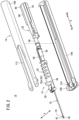
Fig. 1 is a perspective view of a catheter assembly according to an embodiment of the present invention. -
Fig. 2 is an exploded perspective view of the catheter assembly ofFig. 1 . -
Fig. 3 is an exploded perspective view of an assembly main body ofFig. 2 . -
Fig. 4 is a partially omitted perspective view of the assembly main body ofFig. 2 as viewed obliquely from below. -
Fig. 5 is a partially omitted bottom view of the assembly main body ofFig. 2 . -
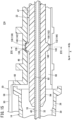
Fig. 6 is a longitudinal cross-sectional view taken along line VI-VI ofFig. 5 . -
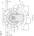
Fig. 7 is a transverse cross-sectional view taken along line VII-VII ofFig. 6 . -
Fig. 8 is a perspective view of a safety member inFig. 3 as viewed obliquely from below. -
Fig. 9 is an explanatory diagram of a method of assembling a safety member to a catheter operation member. -
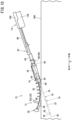
Fig. 10 is a first explanatory diagram of an operation procedure of the catheter assembly ofFig. 1 . -
Fig. 11 is a second explanatory diagram of an operation procedure of the catheter assembly ofFig. 1 . -
Fig. 12 is a third explanatory diagram of an operation procedure of the catheter assembly ofFig. 1 . -
Fig. 13 is a fourth explanatory diagram of an operation procedure of the catheter assembly ofFig. 1 . -
Fig. 14 is a fifth explanatory diagram of an operation procedure of the catheter assembly ofFig. 1 . -
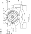
Fig. 15 is a partially omitted longitudinal cross-sectional view of an assembly main body according to a modification example. -
Fig. 16 is a transverse cross-sectional view taken along line XVI-XVI ofFig. 15 . - As illustrated in
Fig. 1 , acatheter assembly 10 according to an embodiment of the present invention is used in a case where infusion, blood transfusion, blood sampling, or the like is performed on a living body. In thecatheter assembly 10, acatheter 24 is inserted into and indwelled in a body to connect the inside of the body with the outside of the body. Thecatheter assembly 10 can insert a catheter longer than a peripheral venous catheter (for example, a central venous catheter, a PICC, a midline catheter, or the like). Note that thecatheter assembly 10 may be configured to allow insertion of the peripheral venous catheter. Furthermore, thecatheter assembly 10 is not limited to the venous catheter, and may be configured to allow insertion of an artery catheter such as a peripheral arterial catheter. - The
catheter assembly 10 extends in one direction (arrow X direction). Thecatheter assembly 10 has a distal end at one end (arrow Xa direction) in an extending direction. Thecatheter assembly 10 has a proximal end at the other end (arrow Xb direction) in the extending direction. In the following description, the arrow Xa direction may be referred to as a "distal end direction", and the arrow Xb direction may be referred to as a "proximal end direction". Hereinafter, the configuration of thecatheter assembly 10 in the initial state will be described. - In
Fig. 2 , thecatheter assembly 10 includes an assemblymain body 12 and agrip 14. The assemblymain body 12 includes acatheter member 16, aneedle member 18, acatheter operation member 20, and asafety member 22. - As illustrated in
Fig. 3 , thecatheter member 16 includes acatheter 24 and acatheter hub 26. Thecatheter 24 has flexibility. Thecatheter 24 has alumen 28 having a size capable of accommodating aninner needle 32 of theneedle member 18 and allowing a medicinal solution, blood, or the like to flow. The distal end (end portion in the arrow Xa direction) of thecatheter 24 is reduced in diameter in order to reduce puncture resistance. - The entire length of the
catheter 24 is not particularly limited, and can be appropriately designed according to use, various conditions, and the like, and is set to, for example, about 14 mm to about 500 mm. Furthermore, the entire length of thecatheter 24 may be set to about 30 mm to about 400 mm. Moreover, the entire length of thecatheter 24 may be set to about 76 mm to about 200 mm. The proximal end (end portion in the arrow Xb direction) of thecatheter 24 is fixed to thecatheter hub 26 by caulking, fusion, adhesion, or the like. - The constituent material of the
catheter 24 is not particularly limited, but a soft resin material is preferable. Specifically, examples of the constituent material of thecatheter 24 include a fluorine-based resin such as polytetrafluoroethylene (PTFE), an ethylene-tetrafluoroethylene copolymer (ETFE), and a perfluoroalkoxy fluorine resin (PFA), an olefin-based resin such as polyethylene and polypropylene or a mixture thereof, polyurethane, polyester, polyamide, a polyether nylon resin, and a mixture of the olefin-based resin and an ethylene-vinyl acetate copolymer. - In
Fig. 6 , thecatheter hub 26 includes alumen 30 communicating with thelumen 28 of thecatheter 24. Thecatheter hub 26 has a tubular shape. A hemostasis valve and a plug (not illustrated) are accommodated in thelumen 30 of thecatheter hub 26. - The constituent material of the
catheter hub 26 is not particularly limited, but a thermoplastic resin is preferable. Specifically, examples of the constituent material of thecatheter hub 26 include polypropylene, polycarbonate, polyamide, polysulfone, polyarylate, and a methacrylate-butylene-styrene copolymer. - As illustrated in
Fig. 3 , theneedle member 18 includes aninner needle 32 and aninner needle hub 34. Theinner needle 32 is a hollow needle having rigidity, which is capable of puncturing a skin 500 (seeFig. 10 ) of the living body. The entire length of theinner needle 32 is longer than the entire length of thecatheter 24. The distal end of theinner needle 32 has asharp needle tip 36. Theinner needle 32 is inserted into thelumen 28 of thecatheter 24. The distal end of theinner needle 32 is exposed from the distal end opening 38 of the catheter 24 (seeFigs. 1 and2 ). - In
Fig. 6 , theinner needle 32 has alumen 40 extending along an axial direction of theinner needle 32. Thelumen 40 communicates with a distal end opening 42 of the inner needle 32 (seeFig. 3 ). Examples of the constituent material of theinner needle 32 include a metal material, a hard resin, and ceramics. Examples of the metal material include stainless steel, aluminum, and titanium. The proximal end of theinner needle 32 is fixed to theinner needle hub 34 by fusion, adhesion, insert molding, or the like. Theinner needle 32 may be a solid needle. - The
inner needle hub 34 extends along the axial direction of theinner needle 32. Theinner needle hub 34 is made of, for example, the same material as that of the above-describedcatheter hub 26. Theinner needle hub 34 is fixed to the grip 14 (seeFig. 2 ). - As illustrated in
Figs. 2 to 4 , thecatheter operation member 20 is operated by a user when thecatheter member 16 is moved along theinner needle 32. Thecatheter operation member 20 covers at least a part of thecatheter 24 from above. Thecatheter operation member 20 is an integrally molded article made of a resin material. Thecatheter operation member 20 has flexibility. In other words, thecatheter operation member 20 is elastically deformable. - In
Figs. 3 and4 , thecatheter operation member 20 includes acatheter attachment portion 44 and aconnection portion 46. Thecatheter attachment portion 44 can be detachably attached to thecatheter member 16. Thecatheter attachment portion 44 extends along the axial direction (arrow X direction) of thecatheter 24. The entire length of thecatheter attachment portion 44 is shorter than the entire length of the catheter member 16 (seeFig. 2 ). - The
catheter attachment portion 44 includes anoperation plate portion 48, acover portion 50, a plurality ofoperation tabs 52, afirst support portion 54, and asecond support portion 56. Theoperation plate portion 48 is located above thecatheter 24. Theoperation plate portion 48 has flexibility. In other words, theoperation plate portion 48 is configured to be bendable in a thickness direction of theoperation plate portion 48. The width of theoperation plate portion 48 is wider than the outer diameter of thecatheter 24. - The
cover portion 50 extends from the proximal end of theoperation plate portion 48 in the proximal end direction (arrow Xb direction). Thecover portion 50 is opened downward. The distal end of thecover portion 50 has a cross-sectional shape in which a U shape is vertically inverted. A portion of thecover portion 50 from the intermediate portion to the proximal end in the extending direction has a transverse cross-sectional shape in which an L shape is vertically inverted. In other words, the portion of thecover portion 50 from the intermediate portion to the proximal end includes acutout portion 58. - That is, a part of the
catheter hub 26 is exposed upward from the cover portion 50 (seeFig. 2 ). That is, thecover portion 50 covers only a part of thecatheter hub 26. InFig. 4 , the proximal end of thecover portion 50 is located on the proximal end side (arrow Xb direction) with respect to the proximal end of thecatheter hub 26. The proximal end of thecover portion 50 has awall portion 60 that covers thecatheter hub 26 from the proximal end direction. - In
Fig. 3 , a plurality of theoperation tabs 52 protrude upward from the upper surface of theoperation plate portion 48. A plurality of theoperation tabs 52 are disposed at intervals along the extending direction of theoperation plate portion 48. Among a plurality of theoperation tabs 52, anoperation tab 52a located closest to the arrow Xa direction protrudes more than a plurality of theother operation tabs 52. - In
Fig. 4 , thefirst support portion 54 protrudes downward from the lower surface of the distal end of theoperation plate portion 48. Thefirst support portion 54 extends along the extending direction of theoperation plate portion 48. Thefirst support portion 54 has a first support slit 62 opened downward. The first support slit 62 extends along the extending direction (arrow X direction) of theoperation plate portion 48. An intermediate portion of thecatheter 24 in the longitudinal direction is detachably fitted to the first support slit 62. In other words, the intermediate portion of thecatheter 24 in the longitudinal direction is detachably inserted into the first support slit 62. Note that, in the inserted state, a gap may be present between the intermediate portion of thecatheter 24 in the longitudinal direction and the inner surface of the first support slit 62. - The
second support portion 56 is located at the distal end of thecover portion 50. Thesecond support portion 56 has a second support slit 64 opened downward. The proximal end of thecatheter 24 is detachably fitted to the second support slit 64. In other words, the proximal end of thecatheter 24 is detachably inserted into the second support slit 64. Note that, in the inserted state, a gap may be present between the proximal end of thecatheter 24 and the inner surface of the second support slit 64. - In
Figs. 3 to 6 , theconnection portion 46 extends in the proximal end direction from the proximal end (wall portion 60) of thecatheter attachment portion 44. Thesafety member 22 is separably connected to theconnection portion 46. Theconnection portion 46 has a tubular shape. InFig. 5 , theconnection portion 46 is formed with aslit 66 extending along the axial direction (arrow X direction) of theconnection portion 46. That is, theconnection portion 46 has a C-shape in cross section (seeFig. 7 ). Theslit 66 is provided on the lower surface of theconnection portion 46. - The
slit 66 extends linearly over the entire length of theconnection portion 46. The groove width of theslit 66 is larger than the outer diameter of theinner needle 32 and smaller than the outer diameter of aneedle protection portion 84 of thesafety member 22, theneedle protection portion 84 being to be described later. Arecess 70 is formed in each of a pair of grooveinner surfaces 68 forming theslit 66. - A pair of the
recesses 70 face each other with theslit 66 interposed therebetween. The portion of theslit 66 interposed between a pair of therecesses 70 and a pair of therecesses 70 constitute a firstfitting portion 72 for connecting thesafety member 22. The firstfitting portion 72 is afitting hole 74 provided in theconnection portion 46. The firstfitting portion 72 is located on the midway of theconnection portion 46 in the axial direction. Specifically, the firstfitting portion 72 is located on the distal end side with respect to the center of theconnection portion 46 in the axial direction. - The
recess 70 is formed in a trapezoidal shape in a bottom view of theconnection portion 46. The length of therecess 70 along the arrow X direction decreases outward in the width direction of theslit 66. Therecess 70 is surrounded by a first inclinedinner surface 76, an intermediateinner surface 78, and a second inclinedinner surface 80. Each of the first inclinedinner surface 76, the intermediateinner surface 78, and the second inclinedinner surface 80 is a flat surface. - The first inclined
inner surface 76 is connected to a portion of the grooveinner surface 68 located on the distal end side with respect to therecess 70. The first inclinedinner surface 76 is inclined outward in the width direction of theslit 66 toward the proximal end (arrow Xb direction) of theconnection portion 46. The intermediateinner surface 78 is connected to an end of the first inclinedinner surface 76 in the arrow Xb direction. The intermediateinner surface 78 extends along the axial direction of theconnection portion 46. - The second inclined
inner surface 80 is connected to an end of the intermediateinner surface 78 in the arrow Xb direction. The second inclinedinner surface 80 is inclined inward in the width direction of theslit 66 toward the proximal end (arrow Xb direction) of theconnection portion 46. The second inclinedinner surface 80 is connected to a portion of the grooveinner surface 68 located on the proximal end side with respect to therecess 70. The second inclinedinner surface 80 is afirst restriction portion 82 for restricting the movement of thesafety member 22 in the proximal end direction with respect to theconnection portion 46. - As illustrated in
Fig. 8 , thesafety member 22 includes aneedle protection portion 84, a secondfitting portion 86, asupport plate portion 88, and astopper portion 90. Theneedle protection portion 84 is a tubular portion extending along the arrow X direction. That is, theneedle protection portion 84 has alumen 92 into which theinner needle 32 is inserted. Thelumen 92 extends over the entire length of theneedle protection portion 84. Theneedle protection portion 84 is inserted into alumen 47 of the connection portion 46 (seeFigs. 6 and7 ). In the initial state of thecatheter assembly 10, the distal end of theneedle protection portion 84 is located in thelumen 30 of the catheter hub 26 (seeFig. 6 ). - The second
fitting portion 86 is afitting protrusion 94 protruding downward from the lower surface of theneedle protection portion 84. The secondfitting portion 86 is located on the distal end side with respect to the center of theneedle protection portion 84 in a longitudinal direction. In the initial state of thecatheter assembly 10, the second fitting portion 86 (fitting protrusion 94) is fitted to the first fitting portion 72 (fitting hole 74) (seeFigs. 4 and5 ). The secondfitting portion 86 has a shape corresponding to the firstfitting portion 72. The secondfitting portion 86 is formed in a hexagonal shape when viewed from below. - As illustrated in
Fig. 5 , the outer peripheral surface of the secondfitting portion 86 includes a pair of first inclinedouter surfaces 96, a pair of intermediateouter surfaces 98, and a pair of second inclined outer surfaces 100. A pair of the first inclinedouter surfaces 96, a pair of the intermediateouter surfaces 98, and a pair of the second inclinedouter surfaces 100 are flat surfaces. - Each of the first inclined
outer surfaces 96 is inclined outward in the width direction (arrow Y direction) of the secondfitting portion 86 from the end of the secondfitting portion 86 in the arrow Xa direction toward the arrow Xb direction. Each of the intermediateouter surfaces 98 is connected to an end of the first inclinedouter surfaces 96 in the arrow Xb direction. The intermediateouter surface 98 extends along the axial direction of theneedle protection portion 84. Each of the second inclinedouter surfaces 100 is inclined inward in the width direction of the secondfitting portion 86 from the proximal end of the intermediateouter surface 98 toward the arrow Xb direction. - In the initial state of the
catheter assembly 10, the first inclinedouter surface 96 is located to face the first inclinedinner surface 76, the intermediateouter surface 98 is located to face the intermediateinner surface 78, and the second inclinedouter surface 100 is located to face the second inclinedinner surface 80. The second inclinedouter surface 100 is asecond restriction portion 102 that can come into contact with the second inclined inner surface 80 (first restriction portion 82) in a state where thesafety member 22 is connected to thecatheter operation member 20. Thesecond restriction portion 102 is located on the distal end side with respect to thefirst restriction portion 82 in the initial state of thecatheter assembly 10. - In
Fig. 8 . thesupport plate portion 88 extends in the proximal end direction (arrow Xb direction) from the proximal end of theneedle protection portion 84. InFigs. 7 and8 , thestopper portion 90 protrudes downward from the proximal end of thesupport plate portion 88. Thestopper portion 90 is located at an end of thesupport plate portion 88 in the arrow Y direction. The surface of thestopper portion 90 facing the arrow Xa direction has a portion inclined downward in the arrow Xb direction. - In
Fig. 2 , thegrip 14 has a size and a shape, with which the user can easily grip thegrip 14. Thegrip 14 extends in the arrow X direction. Thegrip 14 covers the proximal end of the assemblymain body 12. Thegrip 14 includes alower cover portion 104 and anupper cover portion 106. - The
inner needle hub 34 is fixed to thelower cover portion 104. Thesafety member 22 is provided on thelower cover portion 104 so as to be slidable in the arrow X direction. Amovement restriction portion 108 and a holdingportion 110 are provided at the distal end of thelower cover portion 104. - The
movement restriction portion 108 is a wall portion located on the distal end side with respect to thestopper portion 90 of thesafety member 22. When thestopper portion 90 comes into contact with themovement restriction portion 108, the movement of thesafety member 22 in the distal end direction with respect to thegrip 14 is prevented. The holdingportion 110 is located away from themovement restriction portion 108 in the arrow Xb direction. The holdingportion 110 is configured such that thestopper portion 90 can pass over in the distal end direction but cannot pass over in the proximal end direction. The holdingportion 110 prevents the movement of thesafety member 22 in the proximal end direction with respect to thegrip 14. - As illustrated in
Fig. 2 , anopening portion 112 for exposing thecatheter operation member 20 is formed in theupper cover portion 106. A plurality of theoperation tabs 52 are exposed to the outside from theopening portion 112 of theupper cover portion 106. Thegrip 14 supports theoperation plate portion 48 of thecatheter operation member 20 so as to be slidable in the arrow X direction. - Next, a method of assembling the
safety member 22 to thecatheter operation member 20 will be described. As illustrated inFig. 9 , the distal end of thesafety member 22 is inserted into thelumen 47 of theconnection portion 46 from the proximal end side of thecatheter operation member 20. - Then, since the groove
inner surfaces 68 of theslit 66 are pressed outward in the width direction of theslit 66 by the secondfitting portion 86, the groove width of the portion of theslit 66 located on the arrow Xb direction side with respect to the firstfitting portion 72 is widened. Therefore, the secondfitting portion 86 can be pushed into the first fitting portion 72 (fitting hole 74) through theslit 66. - When the second
fitting portion 86 is fitted to the firstfitting portion 72, the pressing force acting on the grooveinner surface 68 is released. Therefore, the portion of theslit 66 located on the arrow Xb direction side with respect to the firstfitting portion 72 returns to the original shape. Thus, the assembly of thesafety member 22 to thecatheter operation member 20 is completed. - Next, an operation procedure of the
catheter assembly 10 will be briefly described. In the case of using thecatheter assembly 10, as illustrated inFig. 10 , theskin 500 is punctured with the distal end (theinner needle 32 and the catheter 24) of thecatheter assembly 10. At this time, theneedle tip 36 of theinner needle 32 is located in the blood vessel. - Next, the user grips the
operation tab 52 with fingers and moves thecatheter operation member 20 toward the distal end of thecatheter 24. Then, thecatheter member 16 moves in the distal end direction along theinner needle 32. At this time, since the second inclined inner surface 80 (first restriction portion 82) of thecatheter operation member 20 pushes the second inclined outer surface 100 (second restriction portion 102) of thesafety member 22 in the distal end direction, thesafety member 22 moves in the distal end direction together with thecatheter operation member 20. - Note that, at this time, since the
safety member 22 is movable in the distal end direction with respect to thegrip 14, a large force that causes the secondfitting portion 86 to come out from the firstfitting portion 72 in the proximal end direction does not act on theconnection portion 46. That is, the connection between thecatheter operation member 20 and thesafety member 22 is maintained in a state where the second inclinedouter surface 100 and the second inclinedinner surface 80 are brought into contact with each other. - Furthermore, the user separates the
catheter 24 from the first support slit 62 by curving theoperation plate portion 48 upward while moving thecatheter operation member 20. Note that theoperation plate portion 48 is located on theskin 500 in a curved state. Thus, thecatheter operation member 20 is detached from thegrip 14. Therefore, thecatheter 24 is indwelled in the blood vessel, and thecatheter operation member 20 is detached from thegrip 14. - Subsequently, the user pulls back the
grip 14 in the proximal end direction (arrow Xb direction) while holding thecatheter operation member 20. Then, since theinner needle 32 moves in the proximal end direction together with thegrip 14 with respect to thecatheter member 16, theneedle tip 36 is located in thelumen 92 of theneedle protection portion 84 of the safety member 22 (seeFig. 11 ) . - Furthermore, in this state, as illustrated in
Fig. 12 , thestopper portion 90 of thesafety member 22 passes over the holdingportion 110 in the distal end direction and comes into contact with themovement restriction portion 108, such that the movement of thesafety member 22 in the arrow X direction with respect to thegrip 14 is prevented. Accordingly, the relative movement of theneedle member 18 fixed to thegrip 14 and thesafety member 22 along the arrow X direction is prevented, and thus theneedle tip 36 is not exposed again from theneedle protection portion 84 of thesafety member 22. - Thereafter, when the
grip 14 is further pulled back in the proximal end direction in a state of holding thecatheter operation member 20, as illustrated inFig. 13 , while a pair of the second inclined outer surfaces 100 (second restriction portion 102) of the secondfitting portion 86 pushes and expands a pair of the second inclined inner surfaces 80 (first restriction portion 82) of the secondfitting portion 86 outward in the width direction of theslit 66, a pair of the second inclined outer surfaces 100 (second restriction portion 102) of the secondfitting portion 86 passes over the second inclined inner surfaces 80. Thus, since the groove width of the portion of theslit 66 on the proximal end side is wider than the firstfitting portion 72, the secondfitting portion 86 can be pulled out from theslit 66 in the proximal end direction. Then, when the distal end of theneedle protection portion 84 comes out of theconnection portion 46, thesafety member 22 is separated from thecatheter operation member 20. - Next, as illustrated in
Fig. 14 , thecatheter operation member 20 is removed from thecatheter member 16. Specifically, thecatheter 24 is removed from the second support slit 64 by lifting thecatheter operation member 20 upward with respect to thecatheter member 16. - The present embodiment has the following effects.
- According to the present embodiment, when the
catheter operation member 20 is moved in the distal end direction to advance thecatheter 24 in a state where the living body is punctured with theinner needle 32, thesecond restriction portion 102 of thesafety member 22 can be pushed in the distal end direction by thefirst restriction portion 82 of thecatheter operation member 20. Thus, thesafety member 22 can be moved in the distal end direction along with the operation of thecatheter operation member 20. - Furthermore, when the
safety member 22 is pulled back in the proximal end direction from thecatheter operation member 20 after thecatheter 24 is advanced, thefirst restriction portion 82 is pressed in the proximal end direction by thesecond restriction portion 102, and thus theconnection portion 46 can be elastically deformed. Thus, thesafety member 22 can be separated from thecatheter operation member 20 by causing thesecond restriction portion 102 to pass over thefirst restriction portion 82 in the proximal end direction. Therefore, theneedle member 18 can be removed from thecatheter member 16 while protecting theneedle tip 36 by using thesafety member 22. - In this case, since the
first restriction portion 82 is provided in theconnection portion 46 of thecatheter operation member 20 and thesecond restriction portion 102 is provided in thesafety member 22, the configurations of thecatheter operation member 20 and thesafety member 22 can be simplified. Therefore, the size of thecatheter assembly 10 can be reduced and the manufacturing cost can be suppressed. - The
connection portion 46 has a tubular shape. Theslit 66 is formed in theconnection portion 46 along the axial direction of theconnection portion 46. - According to such a configuration, when the
safety member 22 is pulled back in the proximal end direction from thecatheter operation member 20, theconnection portion 46 is easily elastically deformed radially outward. - The
connection portion 46 includes the firstfitting portion 72. Thesafety member 22 includes theneedle protection portion 84 inserted into thelumen 47 of theconnection portion 46 in the initial state and the secondfitting portion 86 provided in theneedle protection portion 84 and fitted to the firstfitting portion 72 in the initial state. Thefirst restriction portion 82 is provided in the firstfitting portion 72. Thesecond restriction portion 102 is provided in the secondfitting portion 86. - In such a configuration, the
safety member 22 can be easily connected to theconnection portion 46 of thecatheter operation member 20 by fitting the firstfitting portion 72 and the secondfitting portion 86 to each other. - The first
fitting portion 72 is located on the midway of theconnection portion 46 in the axial direction. - In such a configuration, in a case where the
safety member 22 is pulled back in the proximal end direction from thecatheter operation member 20, the firstfitting portion 72 can be brought into contact with theconnection portion 46 until the firstfitting portion 72 is completely removed from theconnection portion 46 after the fitting between the firstfitting portion 72 and the secondfitting portion 86 is released (thesecond restriction portion 102 passes over thefirst restriction portion 82 in the proximal end direction). Thus, it is possible to prevent thesafety member 22 from vigorously coming off from thecatheter operation member 20 when the fitting between the firstfitting portion 72 and the secondfitting portion 86 is released. - The first
fitting portion 72 is located on the distal end side with respect to the center of theconnection portion 46 in the axial direction. - In such a configuration, it is possible to further prevent the
safety member 22 from vigorously coming off from thecatheter operation member 20 when the fitting between the firstfitting portion 72 and the secondfitting portion 86 is released. - The first
fitting portion 72 is provided on the grooveinner surfaces 68 forming theslit 66. - In such a configuration, the first
fitting portion 72 can be easily provided in theconnection portion 46. Furthermore, it is easy to release the fitting between the firstfitting portion 72 and the secondfitting portion 86. - The first
fitting portion 72 is afitting hole 74. The secondfitting portion 86 is afitting protrusion 94 that can be fitted into thefitting hole 74. - In such a configuration, since it is not necessary to form a recess in the
needle protection portion 84, the thickness of theneedle protection portion 84 does not become too thin. - Next, an assembly
main body 12A according to a modification example will be described. In the present modification example, the same components as those of the above-described assemblymain body 12 are denoted by the same reference numerals, and the detailed description thereof will be omitted. In the present modification example, the same effect is obtained for the same configuration as that of the above-described assemblymain body 12. - As illustrated in
Figs. 15 and16 , in the assemblymain body 12A, the structures of a firstfitting portion 130 and a secondfitting portion 132 are different from the structures of the firstfitting portion 72 and the secondfitting portion 86 of the assemblymain body 12 described above. The firstfitting portion 130 is located on the distal end side with respect to the center of theconnection portion 46 in the axial direction. The firstfitting portion 130 is afitting recess 134 provided on an inner surface forming thelumen 47 of theconnection portion 46. The firstfitting portion 130 extends along the circumferential direction of theconnection portion 46. Opposite ends of the firstfitting portion 130 in the extending direction communicate with theslit 66. - In
Fig. 15 , the inner surface forming thefitting recess 134 includes a first inclinedinner surface 136, an intermediateinner surface 138, and a second inclinedinner surface 140. The first inclinedinner surface 136 is inclined outward in the radial direction of theconnection portion 46 toward the proximal end of theconnection portion 46. The intermediateinner surface 138 is connected to an end of the first inclinedinner surface 136 in the arrow Xb direction. The intermediateinner surface 138 extends along the axial direction of theconnection portion 46. - The second inclined
inner surface 140 is connected to an end of the intermediateinner surface 138 in the arrow Xb direction. The second inclinedinner surface 140 is inclined inward in the radial direction of theconnection portion 46 toward the proximal end of theconnection portion 46. The second inclinedinner surface 140 is afirst restriction portion 142 for restricting the movement of thesafety member 22 in the proximal end direction with respect to theconnection portion 46. - The second
fitting portion 132 is afitting protrusion 144 protruding from the outer circumferential surface of theneedle protection portion 84. The secondfitting portion 132 extends along the circumferential direction of theneedle protection portion 84. The secondfitting portion 132 is inserted into thefitting recess 134 which is the firstfitting portion 130 and theslit 66 in the initial state of thecatheter assembly 10. The outer surface of thefitting protrusion 144 has a first inclinedouter surface 146, an intermediateouter surface 148, and a second inclinedouter surface 150. - The first inclined
outer surface 146 is inclined outward in the radial direction of theneedle protection portion 84 from the end of the secondfitting portion 132 in the arrow Xa direction toward the arrow Xb direction. The intermediateouter surfaces 148 is connected to the end of the first inclinedouter surface 146 in the arrow Xb direction. The intermediateouter surface 148 extends along the axial direction of theneedle protection portion 84. The second inclinedouter surface 150 is inclined inward in the radial direction of theconnection portion 46 from the proximal end of the intermediateouter surface 148 toward the arrow Xb direction. - In the initial state of the
catheter assembly 10, the first inclinedouter surface 146 is located to face the first inclinedinner surface 136, the intermediateouter surface 148 is located to face the intermediateinner surface 138, and the second inclinedouter surface 150 is located to face the second inclinedinner surface 140. The second inclinedouter surface 150 is asecond restriction portion 152 that can come into contact with the second inclined inner surface 140 (first restriction portion 142) in a state where thesafety member 22 is connected to thecatheter operation member 20. Thesecond restriction portion 152 is located on the distal end side with respect to thefirst restriction portion 142 in the initial state of thecatheter assembly 10. - In the present modification example, the first
fitting portion 130 is provided on an inner surface forming thelumen 47 of theconnection portion 46. - In such a configuration, as compared with a case where the first
fitting portion 130 is provided only on the grooveinner surface 68 of theslit 66, the size of the first fitting portion 130 (the contact area between thefirst restriction portion 142 and the second restriction portion 152) can be easily changed. Thus, it is easy to set the force necessary for separating thesafety member 22 from thecatheter operation member 20 to an appropriate magnitude. - The second
fitting portion 132 extends along the circumferential direction of theneedle protection portion 84. - In such a configuration, it is possible to relatively increase the force required for the
second restriction portion 152 to pass over thefirst restriction portion 142. - In the present invention, the first fitting portion may be a protrusion, and the second fitting portion may be a recess. Furthermore, both the first fitting portion and the second fitting portion may be protrusions. The catheter assembly may include a blunt needle that is inserted into the lumen of the inner needle. In this case, since the distal end of the blunt needle can protrude from the distal end of the inner needle before the inner needle is removed from the catheter member, it is possible to prevent the catheter from being damaged by the needle tip when the inner needle is removed.
- Note that the present invention is not limited to the above-described embodiment, and various configurations can be taken without departing from the gist of the present invention.
- The present embodiment discloses the following content.
- According to the embodiment described above, there is disclosed a catheter assembly (10) including: a catheter member (16) including a catheter (24) and a catheter hub (26) provided at a proximal end of the catheter; a needle member (18) including an inner needle (32) inserted into a lumen (28) of the catheter and an inner needle hub (34) provided at a proximal end of the inner needle; a catheter operation member (20) provided in the catheter member; and a safety member (22) provided to be movable with respect to the inner needle in an axial direction of the inner needle, in which a needle tip (36) of the inner needle is exposed from the safety member in an initial state, is located on a distal end side with respect to the safety member, and is covered with the safety member in a state where the inner needle is removed from the catheter member, the catheter operation member includes a connection portion (46) that separably connects the safety member and is formed to be elastically deformable, the connection portion includes a first restriction portion (82, 142), the safety member includes a second restriction portion (102, 152) located on a distal end side with respect to the first restriction portion so as to face the first restriction portion in the initial state, and when the safety member is relatively moved to the catheter operation member in a proximal end direction, the catheter operation member and the safety member are separated from each other since the connection portion pressed by the second restriction portion is elastically deformed and the second restriction portion passes over the first restriction portion in the proximal end direction.
- In the catheter assembly, the connection portion may be formed in a tubular shape, and a slit (66) may be formed in the connection portion along an axial direction of the connection portion.
- In the catheter assembly, the connection portion may include a first fitting portion (72, 130), the safety member may include a needle protection portion (84) inserted into a lumen (47) of the connection portion in the initial state, and a second fitting portion (86, 132) provided in the needle protection portion and fitted to the first fitting portion in the initial state, the first restriction portion may be provided in the first fitting portion, and the second restriction portion may be provided in the second fitting portion.
- In the catheter assembly, the first fitting portion may be located on a midway of the connection portion in the axial direction.
- In the catheter assembly, the first fitting portion may be located on the distal end side with respect to a center of the connection portion in the axial direction.
- In the catheter assembly, the first fitting portion may be provided on a groove inner surface (68) forming the slit.
- In the catheter assembly, the first fitting portion may be provided on an inner surface forming the lumen of the connection portion.
- In the catheter assembly, the second fitting portion may annularly extend in a circumferential direction of the needle protection portion.
- In the catheter assembly, the first fitting portion may be a recess or a hole, and the second fitting portion may be a protrusion fittable to the recess or the hole.
-
- 10 Catheter assembly
- 16 Catheter member
- 18 Needle member
- 20 Catheter operation member
- 22 Safety member
- 24 Catheter
- 26 Catheter hub
- 32 Inner needle
- 34 Inner needle hub
- 36 Needle tip
- 46 Connection portion
- 66 Slit
- 72, 130 First fitting portion
- 82, 142 First restriction portion
- 86, 132 Second fitting portion
- 102, 152 Second restriction portion
Claims (9)
- A catheter assembly comprising:a catheter member including a catheter and a catheter hub provided at a proximal end of the catheter;a needle member including an inner needle inserted into a lumen of the catheter and an inner needle hub provided at a proximal end of the inner needle;a catheter operation member provided in the catheter member; anda safety member provided to be movable with respect to the inner needle in an axial direction of the inner needle,wherein a needle tip of the inner needle is exposed from the safety member in an initial state, is located on a distal end side with respect to the safety member, and is covered with the safety member in a state where the inner needle is removed from the catheter member,the catheter operation member includes a connection portion that separably connects the safety member and is formed to be elastically deformable,the connection portion includes a first restriction portion,the safety member includes a second restriction portion located on a distal end side with respect to the first restriction portion so as to face the first restriction portion in the initial state, andwhen the safety member is relatively moved to the catheter operation member in a proximal end direction, the catheter operation member and the safety member are separated from each other since the connection portion pressed by the second restriction portion is elastically deformed and the second restriction portion passes over the first restriction portion in the proximal end direction.
- The catheter assembly according to claim 1,wherein the connection portion is formed in a tubular shape, anda slit is formed in the connection portion along an axial direction of the connection portion.
- The catheter assembly according to claim 2,wherein the connection portion includes a first fitting portion,the safety member includesa needle protection portion inserted into a lumen of the connection portion in the initial state, anda second fitting portion provided in the needle protection portion and fitted to the first fitting portion in the initial state,the first restriction portion is provided in the first fitting portion, andthe second restriction portion is provided in the second fitting portion.
- The catheter assembly according to claim 3,
wherein the first fitting portion is located on a midway of the connection portion in the axial direction. - The catheter assembly according to claim 4,
wherein the first fitting portion is located on the distal end side with respect to a center of the connection portion in the axial direction. - The catheter assembly according to any one of claims 3 to 5,
wherein the first fitting portion is provided on a groove inner surface forming the slit. - The catheter assembly according to any one of claims 3 to 5,
wherein the first fitting portion is provided on an inner surface forming the lumen of the connection portion. - The catheter assembly according to any one of claims 3 to 7,
wherein the second fitting portion annularly extends in a circumferential direction of the needle protection portion. - The catheter assembly according to any one of claims 3 to 8,wherein the first fitting portion is a recess or a hole, andthe second fitting portion is a protrusion fittable to the recess or the hole.
Applications Claiming Priority (2)
| Application Number | Priority Date | Filing Date | Title |
|---|---|---|---|
| JP2022044898 | 2022-03-22 | ||
| PCT/JP2023/008209 WO2023181870A1 (en) | 2022-03-22 | 2023-03-06 | Catheter assembly |
Publications (2)
| Publication Number | Publication Date |
|---|---|
| EP4487895A1 true EP4487895A1 (en) | 2025-01-08 |
| EP4487895A4 EP4487895A4 (en) | 2025-07-09 |
Family
ID=88100641
Family Applications (1)
| Application Number | Title | Priority Date | Filing Date |
|---|---|---|---|
| EP23774469.3A Pending EP4487895A4 (en) | 2022-03-22 | 2023-03-06 | CATHETER ARRANGEMENT |
Country Status (5)
| Country | Link |
|---|---|
| US (1) | US20250010041A1 (en) |
| EP (1) | EP4487895A4 (en) |
| JP (1) | JPWO2023181870A1 (en) |
| CN (1) | CN118076405A (en) |
| WO (1) | WO2023181870A1 (en) |
Family Cites Families (6)
| Publication number | Priority date | Publication date | Assignee | Title |
|---|---|---|---|---|
| US7798994B2 (en) * | 2005-11-15 | 2010-09-21 | Becton, Dickinson And Company | Needle shield to septum interconnect |
| CN104689456B (en) * | 2010-05-14 | 2018-07-13 | C·R·巴德股份有限公司 | catheter placement device and method |
| CN203694357U (en) * | 2013-03-15 | 2014-07-09 | B.布劳恩梅尔松根股份公司 | safety IV catheter |
| JP6718604B2 (en) * | 2015-02-17 | 2020-07-08 | ニプロ株式会社 | Indwelling needle assembly |
| JP7146638B2 (en) | 2016-08-25 | 2022-10-04 | テルモ株式会社 | catheter assembly |
| JP7608427B2 (en) * | 2020-02-20 | 2025-01-06 | テルモ株式会社 | Catheter Assembly |
-
2023
- 2023-03-06 WO PCT/JP2023/008209 patent/WO2023181870A1/en not_active Ceased
- 2023-03-06 EP EP23774469.3A patent/EP4487895A4/en active Pending
- 2023-03-06 JP JP2024509929A patent/JPWO2023181870A1/ja active Pending
- 2023-03-06 CN CN202380013932.7A patent/CN118076405A/en active Pending
-
2024
- 2024-09-19 US US18/890,386 patent/US20250010041A1/en active Pending
Also Published As
| Publication number | Publication date |
|---|---|
| CN118076405A (en) | 2024-05-24 |
| EP4487895A4 (en) | 2025-07-09 |
| WO2023181870A1 (en) | 2023-09-28 |
| JPWO2023181870A1 (en) | 2023-09-28 |
| US20250010041A1 (en) | 2025-01-09 |
Similar Documents
| Publication | Publication Date | Title |
|---|---|---|
| US10238840B2 (en) | Catheter assembly | |
| JP7440491B2 (en) | catheter assembly | |
| US20200061344A1 (en) | Catheter assembly | |
| US10632282B2 (en) | Catheter assembly | |
| US12508402B2 (en) | Catheter assembly | |
| US11291800B2 (en) | Catheter body and hub securing apparatus | |
| WO2009123025A1 (en) | Indwelling needle assembly | |
| JP6941207B2 (en) | Catheter assembly | |
| US20210393920A1 (en) | Catheter assembly | |
| WO2018025968A1 (en) | Catheter assembly | |
| JP7134410B2 (en) | Indwelling needle and indwelling needle assembly | |
| EP4245333A1 (en) | Indwelling needle | |
| US20250010041A1 (en) | Catheter assembly | |
| JP6771406B2 (en) | Catheter assembly | |
| US20220203073A1 (en) | Catheter assembly | |
| JP2016214391A (en) | Catheter assembly | |
| JP7183252B2 (en) | catheter assembly | |
| US20260137907A1 (en) | Catheter assembly | |
| JP2007236825A (en) | Indwelling needle assembly | |
| JP6166358B2 (en) | Catheter assembly | |
| JP7355681B2 (en) | Indwelling catheters and catheter assemblies | |
| JP2019170699A (en) | Catheter assembly | |
| JP2019170828A (en) | Catheter assembly |
Legal Events
| Date | Code | Title | Description |
|---|---|---|---|
| STAA | Information on the status of an ep patent application or granted ep patent |
Free format text: STATUS: THE INTERNATIONAL PUBLICATION HAS BEEN MADE |
|
| PUAI | Public reference made under article 153(3) epc to a published international application that has entered the european phase |
Free format text: ORIGINAL CODE: 0009012 |
|
| STAA | Information on the status of an ep patent application or granted ep patent |
Free format text: STATUS: REQUEST FOR EXAMINATION WAS MADE |
|
| 17P | Request for examination filed |
Effective date: 20240930 |
|
| AK | Designated contracting states |
Kind code of ref document: A1 Designated state(s): AL AT BE BG CH CY CZ DE DK EE ES FI FR GB GR HR HU IE IS IT LI LT LU LV MC ME MK MT NL NO PL PT RO RS SE SI SK SM TR |
|
| DAV | Request for validation of the european patent (deleted) | ||
| DAX | Request for extension of the european patent (deleted) | ||
| A4 | Supplementary search report drawn up and despatched |
Effective date: 20250606 |
|
| RIC1 | Information provided on ipc code assigned before grant |
Ipc: A61M 25/01 20060101ALI20250602BHEP Ipc: A61M 25/00 20060101ALI20250602BHEP Ipc: A61M 25/06 20060101AFI20250602BHEP |