EP4487805A2 - Führungshüllensystem mit positionserfassung - Google Patents
Führungshüllensystem mit positionserfassung Download PDFInfo
- Publication number
- EP4487805A2 EP4487805A2 EP24186702.7A EP24186702A EP4487805A2 EP 4487805 A2 EP4487805 A2 EP 4487805A2 EP 24186702 A EP24186702 A EP 24186702A EP 4487805 A2 EP4487805 A2 EP 4487805A2
- Authority
- EP
- European Patent Office
- Prior art keywords
- intralumenal
- intralumenal device
- distal end
- sensor
- sheath
- Prior art date
- Legal status (The legal status is an assumption and is not a legal conclusion. Google has not performed a legal analysis and makes no representation as to the accuracy of the status listed.)
- Pending
Links
Images










Classifications
-
- A—HUMAN NECESSITIES
- A61—MEDICAL OR VETERINARY SCIENCE; HYGIENE
- A61B—DIAGNOSIS; SURGERY; IDENTIFICATION
- A61B17/00—Surgical instruments, devices or methods
- A61B17/34—Trocars; Puncturing needles
- A61B17/3403—Needle locating or guiding means
-
- A—HUMAN NECESSITIES
- A61—MEDICAL OR VETERINARY SCIENCE; HYGIENE
- A61B—DIAGNOSIS; SURGERY; IDENTIFICATION
- A61B17/00—Surgical instruments, devices or methods
- A61B17/00234—Surgical instruments, devices or methods for minimally invasive surgery
-
- A—HUMAN NECESSITIES
- A61—MEDICAL OR VETERINARY SCIENCE; HYGIENE
- A61B—DIAGNOSIS; SURGERY; IDENTIFICATION
- A61B18/00—Surgical instruments, devices or methods for transferring non-mechanical forms of energy to or from the body
- A61B18/04—Surgical instruments, devices or methods for transferring non-mechanical forms of energy to or from the body by heating
- A61B18/12—Surgical instruments, devices or methods for transferring non-mechanical forms of energy to or from the body by heating by passing a current through the tissue to be heated, e.g. high-frequency current
- A61B18/14—Probes or electrodes therefor
- A61B18/1492—Probes or electrodes therefor having a flexible, catheter-like structure, e.g. for heart ablation
-
- A—HUMAN NECESSITIES
- A61—MEDICAL OR VETERINARY SCIENCE; HYGIENE
- A61B—DIAGNOSIS; SURGERY; IDENTIFICATION
- A61B34/00—Computer-aided surgery; Manipulators or robots specially adapted for use in surgery
- A61B34/20—Surgical navigation systems; Devices for tracking or guiding surgical instruments, e.g. for frameless stereotaxis
-
- A—HUMAN NECESSITIES
- A61—MEDICAL OR VETERINARY SCIENCE; HYGIENE
- A61B—DIAGNOSIS; SURGERY; IDENTIFICATION
- A61B90/00—Instruments, implements or accessories specially adapted for surgery or diagnosis and not covered by any of the groups A61B1/00 - A61B50/00, e.g. for luxation treatment or for protecting wound edges
- A61B90/90—Identification means for patients or instruments, e.g. tags
- A61B90/98—Identification means for patients or instruments, e.g. tags using electromagnetic means, e.g. transponders
-
- A—HUMAN NECESSITIES
- A61—MEDICAL OR VETERINARY SCIENCE; HYGIENE
- A61M—DEVICES FOR INTRODUCING MEDIA INTO, OR ONTO, THE BODY; DEVICES FOR TRANSDUCING BODY MEDIA OR FOR TAKING MEDIA FROM THE BODY; DEVICES FOR PRODUCING OR ENDING SLEEP OR STUPOR
- A61M25/00—Catheters; Hollow probes
-
- A—HUMAN NECESSITIES
- A61—MEDICAL OR VETERINARY SCIENCE; HYGIENE
- A61B—DIAGNOSIS; SURGERY; IDENTIFICATION
- A61B17/00—Surgical instruments, devices or methods
- A61B17/00234—Surgical instruments, devices or methods for minimally invasive surgery
- A61B2017/00238—Type of minimally invasive operation
- A61B2017/00243—Type of minimally invasive operation cardiac
-
- A—HUMAN NECESSITIES
- A61—MEDICAL OR VETERINARY SCIENCE; HYGIENE
- A61B—DIAGNOSIS; SURGERY; IDENTIFICATION
- A61B17/00—Surgical instruments, devices or methods
- A61B17/00234—Surgical instruments, devices or methods for minimally invasive surgery
- A61B2017/00292—Surgical instruments, devices or methods for minimally invasive surgery mounted on or guided by flexible, e.g. catheter-like, means
-
- A—HUMAN NECESSITIES
- A61—MEDICAL OR VETERINARY SCIENCE; HYGIENE
- A61B—DIAGNOSIS; SURGERY; IDENTIFICATION
- A61B17/00—Surgical instruments, devices or methods
- A61B2017/00982—General structural features
-
- A—HUMAN NECESSITIES
- A61—MEDICAL OR VETERINARY SCIENCE; HYGIENE
- A61B—DIAGNOSIS; SURGERY; IDENTIFICATION
- A61B34/00—Computer-aided surgery; Manipulators or robots specially adapted for use in surgery
- A61B34/20—Surgical navigation systems; Devices for tracking or guiding surgical instruments, e.g. for frameless stereotaxis
- A61B2034/2046—Tracking techniques
- A61B2034/2051—Electromagnetic tracking systems
-
- A—HUMAN NECESSITIES
- A61—MEDICAL OR VETERINARY SCIENCE; HYGIENE
- A61B—DIAGNOSIS; SURGERY; IDENTIFICATION
- A61B34/00—Computer-aided surgery; Manipulators or robots specially adapted for use in surgery
- A61B34/20—Surgical navigation systems; Devices for tracking or guiding surgical instruments, e.g. for frameless stereotaxis
- A61B2034/2046—Tracking techniques
- A61B2034/2055—Optical tracking systems
-
- A—HUMAN NECESSITIES
- A61—MEDICAL OR VETERINARY SCIENCE; HYGIENE
- A61B—DIAGNOSIS; SURGERY; IDENTIFICATION
- A61B34/00—Computer-aided surgery; Manipulators or robots specially adapted for use in surgery
- A61B34/20—Surgical navigation systems; Devices for tracking or guiding surgical instruments, e.g. for frameless stereotaxis
- A61B2034/2046—Tracking techniques
- A61B2034/2065—Tracking using image or pattern recognition
-
- A—HUMAN NECESSITIES
- A61—MEDICAL OR VETERINARY SCIENCE; HYGIENE
- A61M—DEVICES FOR INTRODUCING MEDIA INTO, OR ONTO, THE BODY; DEVICES FOR TRANSDUCING BODY MEDIA OR FOR TAKING MEDIA FROM THE BODY; DEVICES FOR PRODUCING OR ENDING SLEEP OR STUPOR
- A61M25/00—Catheters; Hollow probes
- A61M25/01—Introducing, guiding, advancing, emplacing or holding catheters
- A61M25/0105—Steering means as part of the catheter or advancing means; Markers for positioning
- A61M2025/0166—Sensors, electrodes or the like for guiding the catheter to a target zone, e.g. image guided or magnetically guided
Definitions
- This invention relates to guiding sheath and intralumenal devices used with guiding sheaths, such as dilators, therapeutic and diagnostic catheters and transseptal needles.
- Cardiac arrhythmia is irregular beating of the heart caused by aberrant electrical signals. Arrhythmias can reduce quality of life and carry increased risk of stroke and heart failure. Arrythmias can be located and identified via diagnostic catheters. These catheters can be used to create electroanatomical maps to help electrophysiologists understand the pathology and plan and deliver therapy which can include ablation via therapeutic catheters.
- Electrophysiology (EP) catheters are guided by guiding sheaths which are well known for use in facilitating pathway within a patient's vasculature, typically through a femoral artery and aorta to ultimately gain access to the four chambers of the heart.
- guiding sheaths which are well known for use in facilitating pathway within a patient's vasculature, typically through a femoral artery and aorta to ultimately gain access to the four chambers of the heart.
- CARTO .VIZIGO ® Bi-Directional Guiding Sheath by Biosense Webster, Inc., Irvine, California allows for sheath visualization in real-time, three dimensional maps via an imaging electromagnetic system, such as The CARTO ® 3 System by Biosense Webster, Inc. Irvine, California.
- the System enables electrophysiologists to build accurate 3-D electroanatomical maps of the heart and is designed to assist electrophysiologists navigate EP vascular instruments, such as sheaths, catheters, dilators and other probe devices, inside the heart by pinpointing the exact position (location and orientation) of the distal ends of these EP vascular instruments during diagnostic and therapeutic procedures.
- EP vascular instruments such as sheaths, catheters, dilators and other probe devices
- the instrument For visualization of an EP vascular instrument with The CARTO ® 3 System, the instrument carries in or near its distal end an electromagnetic position sensor with three coils, each responsive to a respective magnetic field generators positioned under the patient's bed. Each coil generates a signal that is transmitted by a respective lead wire extending from the distal end of the instrument along its entire length to and through a control handle of the instrument and into an electrical connector which connects with the System for processing and generation of a depiction of the instrument on a monitor displaying a 3-D anatomical map of the heart. Fluoroscopy is often use in lieu of or in addition to electromagnetic position sensing. The ionizing radiation poses a risk to patients and to electrophysiologists who must wear heavy lead-filled garments. Moreover, the view provided is limited to 2D.
- the shaft and distal tip of EP vascular instruments are small by necessity and thus their construction and assembly require highly skilled workers. Moreover, as the field of cardiac electrophysiology advances, more and more components are housed or carried on the instruments' distal ends where space is already at a premium. Furthermore, because the distal ends are advanced into the heart, medical safety requirements are stringent so as to minimize the risk of inadvertent detachment of components from the distal tip or other avoidable traumatic injury to the heart tissue. And, where electrical components in the distal end are connected to lead wires, breakage in the lead wires results in instrument failure.
- intralumental devices such as dilators and transseptal needles that are advanced into patient vasculature
- visualization is often not available.
- the position of the dilator and the transseptal needle is based primarily on guesswork and best estimates of the operators handling these devices. While identification of these devices is possible with fluoroscopy with confirmation by ultrasound, reduction of overall fluoroscopy time is in the interest of the patient's health.
- a catheter shaft for use in a catheter sheath comprises a generally tubular member and an emitter.
- the generally tubular member extends along a longitudinal axis from a proximal end to a distal end.
- the proximal end includes a proximal portion, with the emitter fixed on the proximal portion, and the distal end includes an end effector.
- the end effector includes a septum needle.
- the end effector includes an electrode assembly configured to map an organ.
- the end effector includes an ablation electrode assembly.
- the emitter includes a magnetic member.
- the emitter includes an optically-readable pattern.
- a control handle for use with a catheter sheath includes a pathway along a longitudinal axis of the control handle.
- the pathway is configured to receive a proximal portion of a generally tubular member with an emitter.
- the control handle includes at least one sensor fixed along the pathway and the sensor is responsive to the emitter.
- control handle includes a light source fixed along the pathway.
- the sensor includes a light sensor and the emitter includes an optically-readable pattern.
- the light source is configured to illuminate the optically-readable pattern and the light sensor is configured to detect the optically-readable pattern when illuminated by the light source.
- the light sensor includes a photodiode and the light source includes an LED.
- the emitter includes a magnetic member and the sensor includes a magnetic sensor.
- an intralumenal device position sensing system comprises a catheter sheath with a shaft and a control handle.
- the shaft includes a lumen and the control handle includes a pathway along a longitudinal axis and the pathway and the lumen are in communication with each other.
- a first intralumenal device a first emitter and a sensor.
- the first intralumenal device is configured with a predetermined geometry and includes a proximal portion and a distal portion, the distal portion being configured to extend through the lumen of the sheath and the proximal portion being configured to extend through the pathway of the control handle.
- the first emitter is situated on the proximal portion of the first intralumenal device, and the sensor is situated in the pathway of the control handle, configured to generate signals in response to the first emitter on the proximal portion of the first intralumenal device.
- the signals are representative of a position of the distal portion of the first intralumenal device.
- the first emitter includes a magnetic member and the sensor includes a magnetic sensor.
- the first emitter includes an optically-readable pattern such that an optical signal is emitted when irradiated and the sensor includes an optical unit with at least an optical detector.
- the optical unit includes a light source.
- the first intralumenal device includes a dilator.
- the first intralumenal device includes a lumen configured to receive a second intralumenal device.
- a second emitter is situated on a proximal portion of the second intralumenal device that is configured to be generally coextensive with the proximal portion of the first intralumenal device.
- the second intralumenal device includes a transseptal needle.
- the predetermined geometry includes an insertion length (LIN1) of the first intralumenal device measured proximally from a distal end of the intralumenal device, the insertion length (LIN1) configured to pass through the pathway of the control handle of the guiding sheath and the lumen of the shaft and being greater than a combined length (LT) of the lumen and the pathway by a predetermined distance (DD1).
- LIN1 insertion length of the first intralumenal device measured proximally from a distal end of the intralumenal device
- the insertion length (LIN1) configured to pass through the pathway of the control handle of the guiding sheath and the lumen of the shaft and being greater than a combined length (LT) of the lumen and the pathway by a predetermined distance (DD1).
- the senor is situated along the pathway of the control handle at a predetermined distance (LS1) measured from a distal end of the lumen of the guiding sheath.
- an approach distance AD is defined as a predetermined distance measured proximally from the distal end of the lumen of the guiding sheath.
- the signals generated by the sensor responsive to the third emitter are representative of the distal end of the intralumenal device being even with the distal end of the lumen of the shaft.
- the first emitter includes a magnetic member
- the sensor includes a first magnetic sensor
- the system further comprises a second magnetic sensor situated at a same axial location in the pathway as the first magnetic sensor but at a different angular location about the longitudinal axis of the first intralumenal device.
- the emitter includes a magnetic member and the sensor includes a magnetic sensor, and the magnetic member is situated off-axis relative to a longitudinal axis of the first intralumenal device.
- the first emitter includes a first magnetic strength and the second emitter includes a second magnetic strength different from the first magnetic strength.
- the system includes a second emitter, wherein the first emitter generates a first magnetic field and the second emitter generates a second magnetic field that is orthogonal to the first magnetic field.
- the system includes a second emitter, wherein the first emitter generates a first magnetic field and the second emitter generates a second magnetic field that is off-angle to the first magnetic field.
- the system includes multiple first emitters and multiple sensors, the multiple first emitters situated on the proximal portion of the first intralumenal device that form a first linear array of first emitters, each of the first emitters situated at a different axial location along the proximal portion of the first intralumenal device, the multiple sensors situated in the pathway of the control handle that form a linear array of sensors, each of the sensors situated at a different axial location along the pathway.
- the first intralumenal device is configured such that the distal portion is deflectable.
- the signals generated by the sensor in response to the second emitter are representative of a position of the distal portion of the second intralumenal device when deployed past a distal end of the first intralumenal device.
- an intralumenal device position sensing system includes a guiding sheath with a shaft and a control handle, the shaft including a lumen, and the control handle defining a pathway therein along a longitudinal axis, the pathway and the lumen in communication with each other
- the system also includes a first intralumenal device with a predetermined geometry, the first intralumenal device including a proximal portion and a distal portion, the distal portion configured to extend through the lumen of the sheath and the proximal portion configured to extend through the pathway of the control handle.
- the system further includes a first optically-readable pattern situated on the proximal portion of the first intralumenal device, and an optical source and an optical sensor situated in the pathway of the control handle, the optical source configured to illuminate the first optically-readable pattern, the optical sensor configured to generate signals in response to illumination of the first optically-readable pattern by the optical source, the signals being representative of a position of the distal portion of the first intralumenal device.
- the optical source includes an LED.
- the optical sensor includes a photodiode.
- the system includes a second optically-readable pattern situated on the proximal portion of the first intralumenal device at a second location different from a first location of the first optically-readable pattern.
- the system includes a second optically-readable pattern situated on the proximal portion of the first intralumenal device at a second location diametrically opposite from a first location of the first optically-readable pattern.
- the system includes multiple optical emitters and multiple optical sensors that form respective pairs of an optical emitter and an optical sensor, each pair situated at a different axial location along the pathway.
- an intralumenal device position sensing system includes a guiding sheath with a shaft and a control handle, the shaft including a lumen, and the control handle that defines a pathway therein along a longitudinal axis, the pathway and the lumen in communication with each other.
- the system also includes a first intralumenal device with a predetermined geometry, the first intralumenal device including a proximal portion and a distal portion, the distal portion configured to extend through the lumen of the sheath and the proximal portion configured to extend through the pathway of the control handle.
- the system further includes means for determining position of the distal portion of the first intralumenal based on position of the proximal portion of the first intralumenal device in the pathway of the control handle.
- the position of the distal position includes a position of the distal portion deployed past a distal end of the shaft of the guiding sheath.
- the means for determining position includes electromagnetic emitter and electromagnetic sensor.
- the means for determining position includes optical source and optical sensor.
- a method for determining position of an intralumenal device includes determining a first length of a guiding sheath that includes a shaft and a control handle, the first length defined between a distal end of the sheath and a sensor site in the control handle, and determining a position of the distal end of the sheath within a patient's body. The method also includes determining a second length of an intralumenal device configured to pass through the shaft and control handle of the guiding sheath, the second length defined between a distal end of the intralumenal device and an emitter site on a proximal portion of the intralumenal device that coincides in the control handle.
- the method further includes determining a position of the emitter site of the intralumenal device relative to the control handle, and determining a position of a distal end of the intralumenal device in the patient's body based on the determined location of the emitter site of the intralumenal device.
- the determining a position of the emitter site of the intralumenal device relative to the control handle includes electromagnetic sensing.
- the determining a position of the emitter site of the intralumenal device relative to the control handle include optical sensing.
- the determining a position of the distal end of the sheath within a patient's body includes electromagnetic position sensing.
- the method includes displaying a graphical representation of the position of the distal end of the intralumenal device.
- the position of the distal end of the intralumenal device includes linear position.
- the position of the distal end of the intralumenal device includes rotational position.
- a system in some embodiments, includes a sheath comprising a handle and a catheter tube extending distally from the handle, and an intralumenal device comprising a shaft configured with a predetermined geometry and being configured to traverse through the handle and the catheter tube.
- the system also includes a sensor assembly disposed approximate the handle and configured to determine a length of insertion of the intralumenal device within the sheath to thereby determine a position of a distal end of the shaft.
- the system further includes a processor; and a non-transitory computer readable medium with instructions thereon, that when executed by the processor, cause the system to determine the length of insertion of the intralumenal device within the sheath, and determine the position of a distal end of the shaft based at least in part on the length of insertion of the intralumenal device within the sheath and the predetermined geometry of the shaft.
- the sheath includes a navigation sensor approximate a distal end of the catheter tube.
- a distal portion of the catheter tube includes a curvature
- a distal portion of the shaft includes a pre-shaped curvature
- a distal portion of the catheter tube is deflectable.
- a distal portion of the shaft lacks a navigation sensor.
- the system includes a transseptal puncture kit comprising the sheath and the intralumenal device.
- the intralumenal device includes a transseptal needle.
- the intralumenal device includes a dilator.
- the shaft of the intralumenal device is non-deflectable.
- the intralumenal device includes an identification marker
- the handle includes an identification circuit configured to determine the predetermined geometry of the shaft based at least in part on the identification marker.
- the identification marker includes a radio frequency identification (RFID) circuit.
- RFID radio frequency identification
- the sensor assembly includes a sensor array within the handle of the sheath and a sensor marker disposed on a proximal portion of the shaft of the intralumenal device, the sensor array being configured to determine a position of the sensor marker within the handle to thereby determine the position of a distal end of the shaft.
- the sensor array includes a length approximately equal to a length of a distal portion of the shaft that is distal of a distal end of the catheter tube of the sheath when the intralumenal device is fully distally inserted into the sheath.
- the sensor marker includes a ferromagnetic material, and the sensor array comprising a plurality of magnetic sensors.
- the sensor array includes a plurality of sensors arranged linearly along a longitudinal axis and adjacent to a lumen within the handle, the lumen being configured to receive the shaft of the intralumenal device.
- the system also includes a processor; and a non-transitory computer readable medium with instructions thereon, that when executed by the processor, cause the system to determine the position of the sensor marker within the handle based at least in part on an electrical signal from the sensor array, and determine the position of the distal end of the shaft of the intralumenal device based at least in part on the electrical signal from the sensor array and the predetermined geometry of the shaft.
- the computer readable medium includes instructions, that when executed by the processor, cause the system to determine a position of the distal end of the intralumenal device within the body of a patient.
- the computer readable medium includes instructions, that when executed by the processor, cause the system to determine a position of the distal end of the intralumenal device within the heart of the patient.
- the computer readable medium includes instructions, that when executed by the processor, cause the system to determine a position of the distal end of the intralumenal device in relation to the fossa ovalis within the heart of the patient.
- the computer readable medium includes instructions, that when executed by the processor, cause the system to determine a position of a navigation sensor disposed on a distal portion of the catheter tube, and determine a position of the distal end of the intralumenal device in relation to the navigation sensor.
- the computer readable medium includes instructions, that when executed by the processor, cause the system to determine the predetermined geometry of the shaft based at least in part on an identification marker on the intralumenal device.
- a system includes a processor; and a non-transitory computer readable medium with instructions thereon, that when executed by the processor, cause the system to determine a length of insertion of a shaft of an intralumenal device within a sheath, the shaft comprising a predetermine geometry, the sheath comprising a handle and a catheter tube extending distally from the handle, and determine a position of a distal end of the shaft based at least in part on the length of insertion of the intralumenal device within the sheath and the predetermined geometry of the shaft.
- the computer readable medium includes instructions, that when executed by the processor, cause the system to determine a position of a navigation sensor disposed on a distal portion of the catheter tube; and determine a position of the distal end of the intralumenal device in relation to the navigation sensor.
- the computer readable medium includes instructions, that when executed by the processor, cause the system to determine a position of a distal portion of the catheter tube within the body of a patient, and determine a position of the distal end of the shaft within the body of the patient based at least in part on the position of the distal portion of the catheter tube, the length of insertion of the intralumenal device, and the predetermined geometry of the shaft.
- the computer readable medium incudes instructions, that when executed by the processor, cause the system to provide a display output comprising a graphical representation of the position of the distal end of the shaft in the body.
- the computer readable medium includes instructions, that when executed by the processor, cause the system to determine a position of the distal end of the intralumenal device within the heart of the patient.
- the computer readable medium includes instructions, that when executed by the processor, cause the system to determine a position of the distal end of the intralumenal device in relation to the fossa ovalis within the heart of the patient.
- the computer readable medium includes instructions, that when executed by the processor, cause the system to determine the length of insertion of an intralumenal device within a sheath based at least in part on an electrical signal from a sensor array within the handle.
- a method for visualizing a distal end of an intralumenal device includes determining a position of a distal portion of the sheath within a body of a patient, and determining a length of insertion of a shaft configured with a predetermine geometry within a sheath. The method also includes determining a position of a distal end of the shaft within the body of the patient based at least in part on the length of insertion of the shaft within the sheath, the predetermined geometry of the shaft, and the position of the distal portion of the sheath, and providing a graphical representation of the position of the distal end of the shaft within the body of the patient.
- means for determining position includes first and second conductive members disposed along the pathway, a third conductive member disposed on the proximal portion of the intralumenal device and configured to contact the first and second conductive members in forming a completed electrical circuit when the proximal portion moves along the pathway, and a circuit detector configured to detect the completed electrical circuit.
- the third conductive member includes a ring electrode disposed on the proximal portion of the intralumenal device.
- the system further includes an impedance sensor configured to measure impedance of the completed electrical circuit.
- means for determining position includes a first array of first conductive members and a second array of second conductive members disposed along the pathway, a third array of third conductive members disposed on the proximal portion of the intralumenal device, each third conductive member configured to contact a respective pair of first and second conductors in forming a respective completed electrical circuit when the proximal portion moves along the pathway, and a circuit detector configured to detect a respective completed electrical circuit.
- the system further comprises an impedance sensor to measure impedance of a respective completed electrical circuit.
- the proximal portion of the intralumenal device includes visual indicia disposed between adjacent third conductive members, on an outer surface of the intralumenal device.
- the visual indicia include alphanumeric symbols.
- the visual indicia include colors.
- a system for visualization of intralumenal device includes a lumened device with a first predetermined geometry and including a first proximal portion and a first distal portion and an intralumenal device with a second predetermined geometry, the intralumenal device including a second proximal portion and a second distal portion, the second proximal portion and the second distal portion configured to extend distally through the lumen of the lumened device.
- the system also includes a processor, a display; and a non-transitory computer readable medium with instructions thereon, that when executed by the processor, causes the display to provide visualization representative of the first distal portion with a graphic element representative of an exposed section of the second distal portion extending distally of a distal end of the first distal portion.
- the graphic element comprises a circle with a diameter based on a length of the exposed distal portion.
- the diameter varies in real-time based on a length of the exposed distal portion as the exposed distal portion translate along the pathway.
- the lumened device includes a dilator and the intralumenal device includes a guidewire.
- the system further includes a guiding sheath and a position sensing assembly.
- the guiding sheath includes a control handle and a sheath, the sheath including a third proximal portion and a third distal portion, the sheath configured with a lumen through which the lumened device extends.
- the position sensing assembly is configured to determine a position of the first distal portion of lumened device relative to the third distal portion of the guiding sheath based on a position of the first proximal portion of the lumened device relative to the third proximal portion of the guiding sheath.
- the system further includes a guiding sheath and a position sensing assembly.
- the guiding sheath includes a control handle and a sheath, the sheath including a third proximal portion and a third distal portion, the sheath configured with a lumen through which the lumened device extends.
- the position sensing assembly is configured to determine a position of the second distal portion of the intralumenal device relative to the third distal portion of the guiding sheath based on a position of the second proximal portion of the intralumenal device relative to the third proximal portion of the guiding sheath.
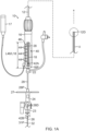
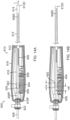
- a guiding sheath 10 includes an elongated flexible catheter tube or sheath 12, and a control handle 16 proximal of sheath 12.
- the sheath 12 is configured with a lumen 14 through which various intralumenal devices can traverse and be guided through a patient's vascular to ultimately reach chambers in the patient's heart.
- the control handle 16 at its proximal end has an electrical connector 17 for connection to a remote control and processing system in transmitting electrical signals for energizing components of the devices and the guiding sheath and/or receiving signals generated or detected by components of the intralumenal devices and the guiding sheath.
- the lumen 14 of the sheath 12 is in communication with a longitudinal pathway 18 provided in the control handle 16.
- the pathway 18 has a length L18 and is configured to receive an intralumenal device that can traverse from the pathway 18 of the control handle 16 into the lumen 14 of the sheath 12.
- a proximal end of the pathway 18 is defined by a hemostatic valve 22 extending proximally from a proximal end of the control handle 16, where access into the proximal end of the pathway 18 is through a fluid-tight seal of the valve 22 that permits entry and passage of the intralumenal device without fluid leaking out or air entering the valve 22.
- a first (or outer) intralumenal device 24 that is advanced through the pathway 18 of the control handle 16 and further through the lumen 14 of the sheath 12 allows a second (or inner) intralumenal device 26 to be passed through a lumen 25 of the first intralumenal device 24.
- the intralumenal devices may include an end effector, for example, a septum needle, an electrode assembly configured to map an organ, and/or an ablation electrode assembly.
- the first intralumenal device 24 is a lumened catheter or dilator that is advanced through the guiding sheath 10 into a patient's heart and followed by a transseptal needle or wire as the second intralumenal device 26 that is advanced through a lumen 25 of the catheter or dilator 24 into the patient's heart.
- the guiding sheath 10 including the sheath 12 and the control handle 16 has a total length LT from a proximal end 16P of the control handle to a distal end of the sheath 12D.
- the device has a handle 27, a valve 23 and a shaft 28. Whereas the shaft 28 is configured for insertion into the guiding sheath 10, the handle 27 and the valve 23 are configured to remain proximal of the control handle 16 of the guiding sheath 10.
- the shaft 28 of the device 24 has a predetermined length LIN1 between a proximal end 28P and a distal end 28D, where the length LIN1 is greater than the length LT of the guiding sheath 10 by at least a length of DD1, such that the distal end 28D of the first intralumenal device 24 has an exposed length of at DD1 past the distal end 12D of the guiding sheath 10 when the first intralumenal device 24 is sufficiently advanced within the guiding sheath for deployment at its distal end 28D (for example, with its handle 27 abutting the proximal end 16P of the control handle 16).
- the first intralumenal device 24 has a total length L24 between the valve 23 and the distal end 28D.
- the second intralumenal device 26 has an elongated body 31 of length LIN2 between a proximal end 26P and a distal end 26D, where the length LIN2 is greater than the total length L24 of the first intralumenal device 24 such that the body 31 has at least a distal exposed length DD2 distal of the distal end 28D of the first intralumenal device 24 (if not also a proximal excess length LEX proximal of the valve 23 of the first intralumenal device 24) when the second intralumenal device 26 is extending through the first intralumenal device 24 with its distal end 26 deployed at the treatment site within the patient's heart, for example, the septum.
- the distal exposed length DD2 of the second intralumenal device 26 may be limited by a stop 26S positioned to set a calibrated maximum advance position of the second intralumenal device 26 relative to the first intralumenal device 24 and/or the guiding sheath 10, in minimizing the risks of inadvertent tissue punctures by the distal end 26D.
- an electrophysiologist inserts the sheath 12 of the guiding sheath 10 into the patient's femoral artery.
- the shaft 28 of the first intralumenal device 24 is inserted through the hemostatis valve 22 into the pathway 18 of the control handle 16 and then further advanced distally into the lumen 14 of the guiding sheath 10.
- the first intralumenal device 24 is advanced distally relative to the guiding sheath 10 until the distal end 28D passes the distal end 12D of the guiding sheath 10.
- the first intralumenal device 24 With distal end 28D exposed, the first intralumenal device 24 is deployed and ready for diagnostic use, therapeutic use and/or receiving the second intralumenal device 26.
- the second instrument 26 is advanced distally through the lumen 25 of the first intralumenal device 24 until the distal end 26D passes the distal end 28D of the first intralumenal device 24. With the distal end exposed 26D, the second intralumenal device 26 is deployed and ready for diagnostic and/or therapeutic use.
- the user's interest in knowing the position of the first intralumenal device 24 generally heightens when the distal end 28D is approaching the distal end 12D of the guiding sheath 10 ( FIG. 1E ) and advancing past it ( FIG. 1F ).
- the heightened interest may continue at least as long as the distal end 28D is exposed outside of the sheath 12.
- Calibrated maximum distal advancement of the first intralumenal device 24 relative to the sheath 12 may be limited by the device handle 27 abutting the hemostatis valve 22 or the proximal end 16P of the control handle 16 of the guiding sheath 10 ( FIG. 1B ).
- the user's interest in knowing the position of the second intralumenal device 26 generally heightens when the distal end 26D is approaching the distal end 28D of the shaft 28 of the first intralumenal device 24 (in solid lines in FIG. 1F ) and advancing past it (in broken lines in FIG. 1F ).
- the heightened interest may continue at least as long as the distal end 26D is exposed outside of the distal end 28D of the first intralumenal device 24.
- both the distal ends of the dilator and the transseptal needle are narrower and/or more steeply tapered relative to the guiding sheath which can be traumatic and injurious to heart tissue if they are advanced too far distally past the distal end 12D of the sheath 12.
- a guiding sheath system in some embodiments, includes components of an advanced electrophysiology ("EP") imaging system S that support components of a position sensing assembly 40 advantageously provided on respective proximal portions of the guiding sheath 10 and of each of the intralumenal devices 24, 26.
- the position sensing assembly 40 provides signals that are generated by the proximal portions of the intralumenal devices 24, 26 and transmitted to the system S via the electrical connector 17 for processing by the system in determining positions (including location and orientation) of the distal ends of the intralumenal devices 24, 26 relative to the guiding sheath 10.
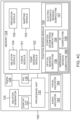
- the EP imaging system S includes a console 122 which may include an ablation power generator 125, a patient interface unit (PIU) 126, and one or more displays 127 and 128 to display 3-D maps and electrograms.
- the operations, functions and acts of the EP imaging system S are managed by the system controller 100 that includes a processing unit 132 communicating with a memory 134 wherein is stored software for operation of the system.
- the system controller 100 is an industry-standard personal computer including a general-purpose computer processing unit.
- the system controller is managed by an operator using a pointing device and a graphical user interface (GUI), which enable the operator to set parameters of the system.
- GUI graphical user interface
- the GUI typically also displays results of the procedure to the operator on a display.
- the software in memory may be downloaded to the controller in electronic form, over a network, for example.
- the software may be provided on non-transitory tangible media, such as optical, magnetic or electronic storage media.
- the memory 134 includes multiple modules used by the processing unit 132, such as, for example, a force sensing module 151, temperature sensing module 152, a 3-D mapping module 153, an ablation module 154, and an irrigation module 155, the functions of which are known in the art, for example, for respectively, measuring tissue temperature, determining position of components within the patient's body with the use of electromagnetic navigation/position sensors responsive to external magnetic field generators positioned outside of the patient's body (for example, below the patient's bed), energizing electrodes to ablate tissue, and controlling flow of irrigation fluid to the treatment site.
- a position sensing module 160 supporting the position sensing assembly and position sensing methods used by the processing unit 132.
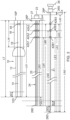
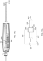
- components of the position sensing assembly 40 include at least emitter 42A advantageously situated on a proximal portion of the first intralumenal device 24 and at least one sensor 44 fixed or otherwise situated along the pathway 18 in the control handle 16 of the guiding sheath 10, such that the emitter 42A and the sensor 44 can interact with each other as the first intralumenal device moves through the pathway 18.
- signals are generated by the sensor in response to the presence and/or movement of the emitter 42A relative thereto wherein such generated signals are indicative of at least the position (linear and/or rotational) of the proximal portion of the first intralumenal device 24 relative to the control handle 16, if not also representative of the position (linear and/or rotational) of the distal end 28D of the first intralumenal device 24 due to its predetermined configurations and geometries.
- components of the position sensing assembly 40 also include at least one emitter 42B advantageously situated on a proximal portion of the second intralumenal device 26, such that the emitter 42B and the sensor 44 can interact with each other as the second intralumenal device moves through the lumen 25 of the first intralumenal device 24.
- signals are generated by the sensor in response to the presence and/or movement of the emitter 42B relative thereto wherein such generated signals are indicative of at least the position (linear and/or rotational) of the proximal portion of the second intralumenal device 26 relative to the control handle, if not also representative of the position (linear and/or rotational) of the distal end 26D of the second intralumenal device 26 due to predetermined configurations and geometries of the intralumenal device 26 and the guiding sheath 10 .
- each of the first and second intralumenal devices 24 and 26 has respective predetermined configurations and geometries such that the spatial relationship between its respective distal end and proximal portion is known and remains generally predictable, whether or not the devices are configured for deflection unidirectionally or bidirectionally (see FIG. 1D ).
- the configurations and geometries of the first and second intralumenal devices and the guiding sheath for use with the system are stored in configurations and geometries subroutine 156 of memory 134 ( FIG. 4B ).
- the system can utilize the signals generated by the sensor in response to the emitter in the proximal portion of each of the first and second intralumenal devices to reliably determine the position (location and orientation) of the respective distal ends of these devices relative to the guiding sheath.
- the sensors 44 are arranged linearly and spaced apart evenly to form an N-by-1 sensor array 46 that has a length L46 that extends along the pathway 18, parallel with a longitudinal axis 48 of the control handle 16.
- the length L46 may be generally equal to the length L18 of the pathway and thus L18 and L46 may be used interchangeably herein.
- N may range between 1 and 10, and preferably be 6 in some embodiments.
- the one or more emitters 42A of the first intralumenal device 24 are supported on a proximal portion of the shaft 28 that is coextensive with the pathway 18 in the immediate proximity of the sensors 44 of the array 46 when the first intralumenal device 24 has been sufficiently advanced into the guiding sheath 10 for deployment past the distal end 12D of the guiding sheath 10.
- the one or more emitters 42B of the second intralumenal device 26 are supported on a proximal portion of an elongated body 31 of the device 26 that extends through the lumen 25 of the shaft 28 and is coextensive with the pathway 18 when the second intralumenal device 26 has been sufficiently advanced into the first intralumenal device 24 for deployment past the distal end 28D of the first intralumenal device 24.
- An approach distance AD of an intralumenal device is defined herein as a predetermined distance within which a user's interest is heightened when a distal tip of the intralumenal device is distally approaching the distal end of the guiding sheath (or of a first or outer intralumenal device).
- An exposed (or deployed) length DD of an intralumenal device is defined herein as a predetermined maximum distance that a user permits a distal end of the intralumenal device to extend past the distal end of the guiding sheath (or of a first or outer intralumenal device),
- the respective intralumenal device 24, 26 may be configured to carry multiple emitters spread along the respective proximal portion for a distance equal to or greater than the length L45 to compensate for the shortage in length of the sensor array L46 relative to the greater exposed length DD1 and/or DD2, with the separation distance between each emitter being dependent at least in part on the length L46 of the sensor array.
- each intralumenal device may carry a single emitter, as scaling is not needed.
- an intralumenal device is not limited to carrying a single emitter and that each intralumenal device may carry multiple emitters, as appropriate or desired.
- the N plurality of sensors 44 in the array 46 and/or the separation distance between adjacent sensors 44 can be varied as desired or appropriate.
- the separation distance between adjacent sensor members 44 in the array 46 is equal or less than the lesser of approach distances AD1, AD2. In some embodiments, the separation distance is equal or less than the lesser of deployed distances DD1, DD2. In some embodiments, the separation distance is equal or less than the lesser of the approach distances AD1, AD2 and the deployed distances DD1, DD2.
- the separation distance between adjacent sensors 44 is less than the distance or field of detection of a sensor 44 so that the detection fields of two adjacent sensors include an overlap and thus an emitter is detected by at least one sensor at any given time while the emitter is within the detection of the sensor array 46.
- the emitters 42A, 42B and the sensor array 46 are enabled by interaction between the emitters 42A, 42B and the sensor array 46 as the intralumenal devices move along the pathway of the control handle.
- the emitters may include magnetic field generating members, for example, permanent or temporary magnets
- the sensors include magnetic field sensors, for example, Hall sensors or coil-based sensors.
- the emitters 42A, 42B are magnetic rings that are carried circumferentially on outer surfaces of the intralumenal devices and are magnetically radially symmetrical about the longitudinal axis of the intralumenal devices, the rings may not adequately provide information on the rotational position (movement or displacement, used interchangeably herein) of the intralumenal devices to the sensor array along the pathway.
- the rings may not adequately provide information on the rotational position (movement or displacement, used interchangeably herein) of the intralumenal devices to the sensor array along the pathway.
- additional magnetic field generating members 42A and 44B are situated off the Z axis on the intralumenal devices 24, 26, respectively, configured in the form of off-axis tabs for interaction with orthogonal (or off-angle at greater or less than 90 degrees) sensors 44x and 44y for detecting and determining "roll" movement and position.
- the sensors 44x and 44y are located in the same axial position (same x/y plane) along the longitudinal axis Z of the control handle 16 but at different angular positions about the longitudinal axis Z.
- the orthogonal (or off angle) sensors 44x, 44y can provide signals representative of rotational movement and displacement in the x/y plane of each intralumenal device.
- multiple sensors 44x extending in the Z axis direction can form a sensor array 46x and multiple sensors 44y extending in the Z axis direction can form a sensor array 46y, where these arrays can generate signals representative of both linear and rotational movement and position of each intralumenal devices as they advance through the guiding sheath 10.
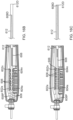
- a pathway 18 of a control handle 16 has a single linear array 46 with a proximal sensor 44P and a distal sensor 44D.
- Extending therethrough is an intralumenal device 24 with a proximal magnetic field emitter 42P and a distal magnetic field emitter 42D configured so that their respective magnetic dipoles or fields are orthogonal to each other.
- the proximal emitter 42P generates magnetic field lines that are perpendicular to the longitudinal axis Z of the intralumenal device 24, whereas the distal emitter 42D generates magnetic field lines that are parallel to the longitudinal axis Z.
- the emitters 42P, 42D may be embedded in the shaft of the intralumenal device.
- the distal emitter 42P is configured with its magnetic field lines parallel to the longitudinal axis Z which produce a changing voltage in a sensor from 0.0V to 3.0V when moved distally past the sensor and a changing voltage from 3.0V to 0.0V when moved proximally past the sensor.
- the signals generated by the distal sensor 44D can be representative of linear position or movement of the intralumenal device 20, and direction of movement.
- the proximal emitter 42D is configured with its magnetic field lines orthogonal to the longitudinal axis Z which produce a changing voltage from 0.0V to 3.0V when the intralumenal device 24 is rotated 180 degrees about its longitudinal axis relative to a sensor.
- the signals generated by the proximal sensor 44P can be representative of rotational position or movement of the intralumenal device 20. Total voltage readings between 0.0 V and 6.0 V are representative of the degree of linear and rotational position and movement.
- a pathway 18 of a control handle 16 has two orthogonal (or off angle) arrays of sensors 46x and 46y and an intralumenal device 20 extending therethrough has a diametrically magnetized member (or ring magnet) 42 with its magnetic field lines being diametrical to the intralumenal device 20 or perpendicular to the longitudinal axis of the intralumenal device 20.
- the emitter member 42 is configured to produce a voltage change in the sensors of both arrays, where a purely linear movement without rotational movement of the intralumenal device 20 produces generally identical responsive signals between each sensor 46x of the orthogonal arrays and generally identical responsive signals between each sensor 46y of the orthogonal arrays, and a purely rotational movement of the intralumenal device 20 without linear movement produces responsive signals in only the orthogonal pair of 46x and 46y in the same axial position.
- a combination of linear and rotational movement in the intralumenal device 20 produces responsive signals in the sensors of both arrays that are representative of the combination movement.
- the components of a position sensing assembly 240 include an optical sensor 252 and an optical emitter (or sensor marker), including, for example, an optically-detectable pattern 254 whose optical emission when illuminated by an optical source 250 is detected by the optical sensor 252.
- the optical source 250 and the optical sensor 252 may form an optical unit in the control handle 16.
- the optically-detectable pattern 254 is provided on a proximal portion 220P of an intralumenal device 220, and the optical source 250 and the optical sensor 252 are situated along a pathway 218 of a control handle 216 of a guiding sheath 210 that receives the intralumenal device 220.
- the optical sensor 252 generates signals in response to the presence, movement and location of the illuminated optically-detectable pattern 254, wherein such generated signals are representative of the displacement and position (linear and/or rotational) of the proximal portion 220P of the intralumenal device 220 relative to the control handle 16, if not also of the distal portion of the intralumenal device relative to the control handle 16.
- a plurality of optical units are provided to form a linear optical array that extends longitudinally along the pathway 18.
- two optical arrays 246a and 246b are provided, diametrically opposing each other along the pathway 18, so as to minimize interference between optical illumination and sensing between the two arrays.
- the optically-detectable pattern may include at least two different patterns 254a and 254b provided on different or opposing locations on the surface of the intralumenal device 220 so that the signals generated by the optical sensor 252 in response to the two different patterns can indicate angular rotation of the intralumenal device 220 about its longitudinal axis.
- the optically-detectable patterns can also be unique to an individual intralumenal device so that each intralumenal device can be identified and limited as a single-use device.
- one or more of the intralumenal devices 24, 26 includes an identification marker 170 and the control handle 16 of the guiding sheath 10 includes an identification circuit 172, as shown in FIG. 2A .
- the identification circuit 172 is configured to determine or identify the predetermined configuration and geometry of the intralumenal device based at least in part on the identification marker 170, which may include a radio frequency identification (RFID) circuit.
- RFID radio frequency identification
- the identification marker 170 may be affixed to a proximal portion of each intralumenal device so that it is read upon insertion into the control handle or shortly after by the identification circuit 172 situated along the pathway 18 of the control handle 16.
- the identification marker 170 may be read by a scan unit 176 separate from or in addition to the identification circuit 172 in the control handle 16, and in communication with an ID subroutine 159 of the position sensing module 160 ( FIG. 4B ).
- the optical source 250 includes an LED
- the optical sensor 252 includes a photodiode
- the optically-detectable pattern 254 as the optical emitter includes a bar code or binary-alternating symbols on multi-axial locations circumferentially on the surface of the intralumenal device 220.
- the optically-detectable pattern as an optical emitter, typically comprising of discrete indicia of dark and light shades reflects light energy in a corresponding pattern that is detected by the optical detector whose output voltage increases with higher reflected light energy and decreases with lower reflected light energy, as shown in FIG. 9 .
- the position sensing assembly 240 may include multiple optical sources 250 and multiple optical detectors 252 arranged in pairs, each pair located at a different location along the pathway 18.
- parameters of the configuration of position sensing assembly 240 depend on a variety of factors, including the size of the field of illumination of each emitter, the length of the optically-detectable pattern, the acceptable degree of uncertainty in the exact location of the intralumenal device relative to the guiding sheath, etc.
- means for determining position including means for determining position of the distal portion of an intralumenal device, are shown and described in one of the many examples in relation to the magnetic field emitters and magnetic field sensors, including, for example, the magnets and the Hall-effect sensors, shown in FIG. 2A and FIG. 2B , and in relation to the optical sensors and the optical emitters illuminated by the optical sources, including, for example, the photodiodes, the optically-readable patterns, and the LEDs, shown in FIG. 8A and FIG. 8B .
- determining position may include determining length, and thus means for determining position may be used interchangeably with means for determining length, as needed or appropriate.
- means for determining position include conductive members configured to complete an electrical circuit and sensors for detecting a completed electrical circuit and sensors for measuring impedance, as discussed further below.
- position sensing assembly is not limited to only electromagnetic components or optical components, and further that both of these types of components may be incorporated and used together as needed or desired.
- an operator has acquired a 3D map of a patient body, including the patient's heart by means of the advanced electrophysiology (EP) imaging system S, such as the CARTO ® 3 System.
- the image generated by the system S that is displayed not only includes the 3D map of the patient's heart, but it also includes depictions of a first (or outer) intralumenal device 24, for example, a dilator, and a second (or inner) intralumenal device 26, for example, a transseptal needle, especially their respective distal ends.
- the user has taken the following actions, including the user using the pointing device and the graphical user interface to enter various user-selectable parameters of the procedure into the system S, including the selection of the guiding sheath and the first and second intralumenal devices to be used in the procedure.
- Geometries and configurations of guiding sheath 10 and of intralumenal devices suitable for use with the system S, including the selected first and second intralumenal devices 24 and 26, have been stored in the configurations and geometries subroutine 156 of the memory 134 ( FIG. 4B ).
- the configurations and geometries provide predictable and reliable determination of the location, position and/or orientation of the distal portion of an intralumenal device based on the location, position and/or orientation of the proximal portion of the intralumenal device in relation to the control handle of a guiding sheath through which intralumenal device extends.
- the system can retrieve from the configuration and geometries subroutine 156 the relevant parameters, including the above-listed parameters, to be used and applied by the position sensing module 160.
- a graphical representation is provided of the position of the distal end of the shaft within the body of the patient.
- the flow chart begins at Block 300.
- Block 302 parameters of the configuration and geometries of a guiding sheath and an intralumenal device are determined and stored in the configurations/geometries subroutine of the memory of the EP imaging system S.
- Block 304 the guiding sheath is inserted into the patient.
- the intralumenal device is inserted into the guiding sheath.
- Block 306 the intralumenal device is advanced relative to the guiding sheath with an emitter on the intralumenal device moving toward a sensor situated in a control handle of the guiding sheath.
- the sensor senses the emitter and generates signals in response to the emitter.
- the position sensing module accesses the parameters and determines the position of the distal end of the intralumenal device based on the signals.
- the EP imaging system S displays the position of the distal end of the intralumenal device. It is understood that position may include location and orientation.
- FIG. 12 In some embodiments of the methods related to the system and device, reference is made to the flow chart of FIG. 12 .
- the flow chart begins with Block 400.
- the parameters of Table 1 are determined and stored in Configurations/Geometries Subroutine of Memory 134.
- the user inserts the guiding sheath 10 into the patient's vasculature, e.g., a femoral artery, and secures the position of the guiding sheath 10 in fixed relationship with the patient.
- the EP imaging system S determines the position of the distal end 12D of the guiding sheath by, for example, an electromagnetic navigation sensor, as known in the art.
- Block 408 the user inserts the first intralumenal device 24 into the lumen 14 of the guiding sheath 10 via the hemostatis valve 22.
- the user advances the device 24 distally toward the distal end 12D of the guiding sheath 10.
- the sensor 44 senses the distal emitter 42A1 and generates signals in response to the emitter 42A1.
- the position sensing module 160 monitors the signals for an event, for example, a peak (a calibrated maximum) or a particular characteristic, as representative of the distal emitter 42A1 being in closest proximity to the sensor 44, in side-by-side alignment therewith, along the longitudinal axis of the control handle 16.
- the position sensing module 160 accesses the parameters stored in the configurations and geometries subroutine 156 based on the signal event.
- the first intralumenal device 24 has a predetermined geometry, for example, including that the position LM1 of the distal emitter 42A1 on the shaft 28 relative to the distal end 28D is equal to the length LS1 (namely, the distance between the sensor 44 and the distal end 12D of the guiding sheath) less the approach distance AD1
- the signals generated by the sensor 44 when the sensor 44 and the distal emitter 42A1 are in their closest proximity, in side-by-side alignment advantageously indicate a relative position between the device 24 and the guiding sheath 10, including that the distal end 28D of the first intralumenal device 24 has reached the approach distance AD1 of the distal end 12D of the guiding sheath.
- a query is made as to whether the event indicates or is related to the distal end 28D reaching the approach distance AD1. If the sensor 44 is generating signals (or a peak signal) in response to the distal emitter 42A1, then the answer to the query is yes and the flow chart continues to Block 420 which activates an indicator, e.g., a visual alarm 160 and/or an audio alarm 162 to notify the user that the distal end 28D has reached the approach distance AD1 and that the distal end 28D may soon protrude from the distal end 12D of the sheath 12, before continuing to Block 422.
- the indicator may automatically terminate after a predetermined duration or remain active until deactivated by the user.
- Block 422 the processing unit 132 displays (or continues to display) the distal end 28D on the display monitor in real time according to the parameters of the configurations and geometries of the first intralumenal device 24 relative to the display of the distal end 12D of guiding sheath within the patient's heart on the display monitor.
- the determined position and display of the distal end 28D of the intralumenal device 24 are advantageously based on signals generated by the proximal end of the first intralumenal device 24.
- a query is made as to whether the first intralumenal device 24 is continuing in its advancement distally relative to the guiding sheath 10. This determination can be made by, for example, assessing changes in the signals sensed by the sensor 44 with reference to the parameters of the first intralumenal device 24. If yes, the flow chart returns to Block 412. As the mid-emitter 42A2 of the first intralumenal device 24 approaches the sensor 44, the sensor 44 senses the mid-emitter 42A2 and generates signals in response to the mid-emitter 42A2.
- the positioning module 160 monitors the signals for an event, for example, a peak (a calibrated maximum) or a particular characteristic, as representative of the mid-emmitter 42A2 being in closest proximity to the sensor 44, in side-by-side alignment therewith, along the longitudinal axis of the control handle 16.
- the position sensing module 160 accesses the parameters stored in the configurations and geometries subroutine 156 for the first intralumenal device 24 and the mid-emitter 42A2 based on the signal event.
- the first intralumenal device 24 has a predetermined geometry, for example, including that the position of the mid-emitter 42A2 on the shaft 28 relative to the distal end 28D is equal to the length LS1, the signals generated by the sensor 44 when it and the mid-emitter 42A2 are in their closest proximity, in side-by-side alignment, advantageously indicate a relative position between the device 24 and the guiding sheath 10, including that the distal end 28D is at the distal end 12D.
- Block 422 the processing unit 132 continues to display on the display monitor in real time the location of the distal end 28D relative to the distal end 12D of guiding sheath within the patient's heart on the display monitor.
- the determined position and display of the distal end 28D of the intralumenal device 24 are advantageously based on signals generated by the proximal end of the first intralumenal device.
- a query is made as to whether the first intralumenal device 24 is continuing in its advancement distally relative to the guiding sheath 10.
- This determination can be made by, for example, assessing changes in the signals sensed by the sensor 44 with reference to the parameters of the first intralumenal device 24 or by input by the user that he is still advancing the first intralumenal device 24. If yes, the flow chart returns to Block 412. Additionally or in lieu, the query of Decision Block 424 may include a determination as to whether the distal end 28D is at maximum deployment distance DD1 by accessing the parameters stored in the configurations and geometries subroutine 146. If no, the flow chart returns to Block 412.
- the loop including Blocks 412, 414, 416, 418, 420, 422 and 424 can be repeated for the proximal emitter 42A3 on the first intralumenal device 24.
- the position sensing module 160 accesses the parameters stored in the configuration and geometries subroutine 156 for the first intralumenal device 24 and the proximal emitter 42A3.
- the first intralumenal device 24 has a predetermined geometry, for example, including that the position of the proximal emitter 42A3 on the shaft 28 relative to the distal end 28D is equal to the length LS1 plus the calibrated maximum exposed distance DD1 of the distal end 28D of the first intralumenal device 24 distal of the distal end 12D of the control handle, the signals generated when the sensor 44 and the proximal emitter 42A3 are in their closest proximity to, in side-by-side alignment, advantageously indicate a relative position between the device 24 and the guiding sheath 10, including that the distal end 28D is at the calibrated maximum exposed length DD1 distal of distal end 12D.
- Block 422 the processing unit 132 continues to display on the display monitor in real time the location of the distal end 28D relative to the distal end 12D of guiding sheath within the patient's heart on the display monitor, where the determined position and display of the distal end 28D are advantageously based on signals generated by the proximal end of the first intralumenal device 24.
- the Decision Block 424 continues to Decision Block 426 with a query as to whether another intralumenal device is to be inserted. This determination may be based on user input. If yes, the flow chart returns to Block 410 where the second intralumenal device 26 is inserted into the first intralumenal device 24 via the valve 23, and advanced distally toward the distal end 28D of the first intralumenal device 24.
- the position sensing module 160 monitors the signals for an event, for example, a peak (a calibrated maximum) or a particular characteristic, as representative of the sensor 44 and the distal emitter 42B1 in closest proximity, in side-by-side in alignment, along the longitudinal axis of the control handle 16.
- the position sensing module 160 accesses the parameters stored in the configurations and geometries subroutine 156 based on the signal event.
- the second intralumenal device 26 has a predetermined geometry, for example, including that the position LE1 of the distal emitter 42B1 on the elongated body 31 relative to the distal end 26D is equal to the length LS1 plus the calibrated maximum exposed distance DD1 of the first intralumenal device 24 less the approach distance AD2, the signals generated when the advantageously indicate a relative position between the device 24 and the guiding sheath 10, including that the distal end 26D of the second intralumenal device 26 is at the approach distance AD2 of the distal end 28D of the first intralumenal device 24.
- the determined position and display of the distal end 26D of the second intralumenal device 26 are advantageously based on signals generated by the proximal end of the second intralumenal device 26.
- the processing unit 132 in response to the signals representative of the distal end 26D being at the approach distance AD2 of the distal end 28D activates the indicator (e.g., the audio alarm 162 or the visual alarm 164) to notify the user that the distal end 26D has reached the approach distance AD2 and that the distal end 26D may soon protrude from the distal end 28D of the first intralumenal device 24.
- the processing unit 132 begins to display the location of the distal end 26D on the display monitor 127 in real time according to the parameters of the configuration and geometry of the second intralumenal device 26, relative to the display of the distal end 28D and the distal end 12D within the patient's heart on the display monitor.
- Block 424 if the user continues to advance the second intralumenal device 26 distally relative to the guiding sheath 10, the flow chart returns to Block 412.
- the loop including Blocks 412, 414, 416, 418, 422 and 424 can be repeated for the mid emitter 42B2 and the proximal emitter 42B3.
- the position sensing module 160 monitors the signals for an event, for example, a peak (a calibrated maximum) or a particular characteristic, as representative of the sensor 44 and the mid-emitter 42B2 being in closest proximity, in side-by-side alignment, along the longitudinal axis of the control handle 16.
- the position sensing module 160 accesses the parameters stored in the configurations and geometries subroutine 156 based on the signal event. Because the second intralumenal device 26 has a predetermined geometry including that the position of the mid emitter 42B2 on the elongated body 31 relative to the distal end 26D is equal to the length LS1 plus the calibrated maximum exposed length DD1 of the first intralumenal device 24, the signals generated when the the sensor 44 and the mid-emitter 42B2 are in closest proximity, in side-by-side alignment, advantageously indicate a relative position between the device 24 and the guiding sheath 10, including that the distal end 26D has reached the distal end 28D.
- the processing unit 132 continues to display on the display monitor in real time the location of the distal end 26D of the second intralumenal device 26 relative to the distal end 28D of the first intralumenal device 24 and the distal end 12D of the guiding sheath 10 within the patient's heart on the display monitor.
- the position sensing module 160 monitors the signals for an event, for example, a peak (a calibrated maximum) or a particular characteristic, as representative of the sensor 44 and the proximal emitter 42B3 in closest proximity, in side-by-side alignment, along the longitudinal axis of the control handle 16.
- the position sensing module 160 accesses the parameters stored in the configurations and geometries subroutine 156 based on the signal event.
- the second intralumenal device 26 has a predetermined geometry of the second intralumenal device 26, for example, including that the position of the proximal emitter 42B3 on the elongated body 31 relative to the distal end 26D is equal to the length LS1 plus the calibrated maximum exposed distance DD1 and the calibrated maximum exposed distance DD2, the signals generated when the sensor 44 and the proximal emitter 42B3 are in closest proximity, in side-by-side alignment, advantageously indicate a relative position between the device 24 and the guiding sheath 10, including that the distal end 26D is at the calibrated maximum exposed length distal of distal end 28D.
- the processing unit 132 continues to display on the display monitor in real time the location of the distal end 26D and the distal end 28D relative to the distal end 12D of guiding sheath within the patient's heart on the display monitor.
- any emitter on the intralumenal devices for example, 42A1, 42A2, 42A3, 42B1, 42B2. 42B3, by the sensor gives rise to signals that are representative of a length of insertion of the intralumenal device whose emitter is being detected because of the predetermined configurations and geometries of the intralumenal device, including, for example, the parameters LM1, LM2, LM3, LE1, LE2, LE3. And further because of the predetermined configurations and geometries of the intralumenal device, a length of insertion can be used to determine position (or at least the location) of a distal end of the intralumenal device relative to the guiding sheath.
- the flow chart accommodates any plurality of emitters so provided the intralumenal device is being advanced relative to the control handle. That is, the loop repeats for each emitter until the Decision Block 424 produces a "no" to the query of whether the intralumenal device is still being advanced relative to the control handle. And, if no other intralumenal device is to be inserted per Decision Block 426, the flow chart may end at Block 428.
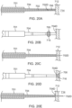
- the signals generated by the sensor 44 in response thereto are also representative of rotation of the first and second intralumenal devices 24 and 26 about their respective longitudinal axes, as shown in FIG. 5A, FIG. 5B and FIG. 5C .
- Parameters include calibrated sensor readings that correspond with rotational angles of the off-axis emitters.
- the parameters accessed include signals values or characteristics that are representative of the position of the distal ends 28D and 26D including location and rotational orientation.
- the predetermined configurations and geometries of the first and second intraluminal devices include predetermined rigidity of the devices over their length and their torsional rigidity such that the application of a translation and/or rotational force at the proximal ends of the devices produces a predictable translation and/or rotation at their distal ends.
- the position sensing module 160 includes a table of calibrations of signal readings corresponding to the longitudinal and rotational positions of each emitter of the first and second intralumenal devices relative to the sensors 44 that may be referenced by the module to determine and/or confirm the relative positions of the emitters on the proximal portion of the devices 24 and 26 to the sensor 44, which are referenced by the processing unit to determine (or reliably predict) the positions of distal ends 28D and 26D of the intralumenal devices 24 and 26 for display on the display monitor.
- the position sensing assembly 600 includes first and second electrically-conductive members (or electrodes) 602, 604 situated along a pathway 618 of a control handle 616 of a guiding sheath 610, and a third electrically-conductive member (or electrode) 606 situated on a proximal portion 608P of an intralumenal device 608 configured for insertion into the pathway 618 and distal advancement through a lumen 614 of a sheath 612 extending distally of the control handle 616.
- the first and second circuit members 602, 604 are separate and distinct from each other and may be disposed, for example, across the pathway 618 from each other, in diametrically opposite positions, and each may have a same dimension or width W along the pathway 618 which is aligned with a longitudinal axis L defined by the control handle 616.
- the third conductive member 606 may be configured as a circumferential band 620 disposed on an outer surface 609 of the intralumenal device 608. The band has a width WB along the longitudinal axis that is equal to or greater than the width W of the first and second.
- a distal end 608D of the intralumenal device 608 is inserted into a hemostatis valve 622 at a proximal end 616P of the control handle 616 to enter the pathway 618.
- the distal end 608D then enters the lumen 614 of the sheath 612 of the guiding sheath 610.
- the proximal portion 608P enters the pathway 618 and the third conductive member 606 approaches the first and second conductive members 602, 604 ( FIG. 14A ).
- the third conductive member 606 comes into contact with both of the first and second conductive members 602, 604 ( FIG. 14B ). As shown in FIG.
- each of the first and second conductive elements 602, 604 is connected to a respective lead wire 625, 627 that extends through an electrical connector (see electrical connector 17 in FIG. 1A ) which enables connection to a power/current source 629.
- the third conductive element 606 completes an electrical circuit 624 that includes the first, third and second conductive members whereupon electrical conductivity is detected ( FIG. 15B ); that is, once the third conductive member 606 is in contact with the first and second conductive members 602, 604, the circuit 624 is completed thereby identifying the presence of the intralumenal device 608.
- the signals generated when the electrical circuit 624 is completed by conductive contact between the first, second and third conductive members 602, 604, 606 advantageously indicate a relative position between the device 608 and the guiding sheath 610, for example, including that the distal end 608D is approaching or protruding from a distal end 612D of the sheath 612.
- the electrical conductivity remains long as there is contact between the members 602 and 606 and between members 606 and 604 during linear translation of the device 608 relative to the control handle 616.
- a system S as shown in FIG. 4C includes a circuit sensing subroutine 165 in a position sensing module 160.
- the system S is configured to determine the position of the proximal portion of the device 608 relative to the control handle 616 and thus the position of the distal end 608D relative to the distal end of the sheath 612 based on the configurations and geometries subroutine 156 of the memory 134 for the device 608.
- the stored configuration and geometry of the device 608 provides predictable and reliable determination of the location, position and/or orientation of the distal end 608D of the device 608 based on the location, position and/or orientation of the proximal portion 608P of the device 608 in relation to the control handle 616 of the guiding sheath 610 through which the device 608 extends.
- the control handle 616 includes a first array A of a plurality of first conductive members 602 and a second array B of a common plurality of second conductive members 604, with each second conductive member being diametrically opposed from a respective first conductive member along the pathway 618 to form a respective pair of separate and distinct conductive members.
- a third array C of a plurality of third conductive members 606 is situated on the proximal portion 608P of the intralumenal device 608 where each of third conductive member 606 can contact a pair of conductive members 602, 604 in completing a respective electrical circuit 624 with the connected pairs 602, 604 with movement of the device 608 relative to the control handle 616,
- the number of circuits completed between a respective pair of first and second conductive members 602, 604 by the third conductive members 606 indicates relative position and movement between the proximal portion 608P of the device 608 and the control handle 616, and thus relative position and movement between the distal end 608D of the device and a distal end 610D of the guiding sheath 610 based on the configuration and geometry of the device 608.
- the completion of each circuit between a respective pair of first and second conductive members 602, 604 by a connecting third conductive member 606 is detected by current sensors A1-AN.
- the system S determines the relative position and movement of the proximal portion 608P of the device 608 and the control handle 616.
- the detection of the completion of circuits A1 indicates the proximal portion 608P is in position P1 relative to the control handle. For example, as shown in FIG.
- the detection of the completion of circuits A1, A2, A3 by third conductive members 606A, 606B, 606C indicates that the proximal portion 608P is in a respective position relative to the control handle 616.
- the detection of the completion of circuits A1, A2, A3, A4 by third conductive members 606A, 606B, 606C, 606D indicates that the proximal portion 608P is in a more distal respective position relative to the control handle 616.
- Each respective position relative to the control handle is determinative of a respective position of the distal end 608D of the device 608 relative to the distal end of the guiding sheath 610 based on known configurations and geometries of the device 608 and the guiding sheath 610. It is understood that the width of and spacing between the conductive members of the arrays A1, A2, A3 can vary depending upon the desired accuracy or resolution of the relative position and movement of the device 608.
- the third conductive members 606 may be configured as ring electrodes or mounted flexible electrodes.
- the proximal portion 608P of the device 608 includes visual indicia 630 configured for viewing by the user in visually notifying the user of the relative position between the device 608 and the control handle 616, and thus the relative position between the distal end 608D of the device 608 and the distal end of the sheath 612 of the guiding sheath 610.
- the visual indicia 630 may include, for example, alphanumeric symbols 630N at selected locations indicating the distances from the respective locations to a proximal end of the device 608, wherein the locations are in between adjacent third conductive members 606.
- the visual indicia 630 may include color-coded marker or bands 630B, for example, a green marker at a distal location D, a yellow marker at a mid-location M and a red marker at a proximal location P, wherein the green marker indicates that the distal end 608D of the device 608 is proximal of the distal end 612D of the sheath 612, the yellow marker indicates that the distal end 608D is approaching the distal end 612, and the red marker indicates that the distal end 608D will soon pass and protrude from the distal end 612 with continued distal advancement.
- a green marker indicates that the distal end 608D of the device 608 is proximal of the distal end 612D of the sheath 612
- the yellow marker indicates that the distal end 608D is approaching the distal end 612
- the red marker indicates that the distal end 608D will soon pass and protrude from the distal end 612 with continued distal advancement.
- the positional value can be correlated to a distance that the distal end 608D of the device 608 protrudes from the distal end 612D of the sheath 612, or an approach distance remaining before the distal tip 608D exits the distal end 612D of the sheath 612.
- a circuit 625 completed by the first, second and third conductive members 602, 604, 606 includes a signal generator 626 and an impedance measuring device 628, e.g., an oscilloscope, an AC volt meter or an impedance meter.
- FIG. 18 is a graph of measured impedance (in Ohms) across the circuit 625 as a function of the distance (displacement) of the third conductive member 606 relative to the first and second conductive members 602, 604, with represents the amount of contact surface area between the first, second and conductive members 602, 604, 606.
- the graph of FIG. 18 shows the measured impedance at a maximum.
- the third conductive member 606 makes contact with the second and third members 602, 604 ( FIG. 14B ) and the measured impedance Z decreases.
- the third conductive member 606 makes full contact with the second and third members ( FIG. 14C ) and the measured impedance decreases further.
- the system S as shown in FIG. 4C includes an impedance subroutine 166 in a position sensing module 160.
- the system S is configured to determine the position of the proximal portion of the device 608 relative to the control handle 616 and thus the position of the distal end 608D relative to the distal end of the sheath 612 based on the configurations and geometries subroutine 156 of the memory 134 for the device 608.
- the stored configuration and geometry of the device 608 provides predictable and reliable determination of the location, position and/or orientation of the distal end 608D of the device 608 based on the location, position and/or orientation of the proximal portion 608P of the device 608 in relation to the control handle 616 of the guiding sheath 610 through which the device 608 extends.
- the system S is configured to provide to the user on a display a visual region-of-interest indicium in real-time 3-D electroanatomical maps via an imaging electromagnetic system, such as The CARTO ® 3 System by Biosense Webster, Inc. Irvine, California.
- an imaging electromagnetic system such as The CARTO ® 3 System by Biosense Webster, Inc. Irvine, California.
- a generated 3-D electroanatomical visualization of an intralumenal device 702 for example, a transseptal guidewire, inserted through a lumen 706 of a lumened device 704, for example, a dilator, inserted through a guiding sheath 701, includes a visual indicium 700 that represents a region of interest ROI occupied by a protruding distal portion 702D.
- the distal portion 702D of the intralumenal device 702 has shape memory such that it is straightened from a predetermined 2-D or 3-D configuration for insertion into and advancement through the lumen 706 and then elastically readopts the predetermined configuration when it exits the lumen or is otherwise unconfined and free from external forces.
- the predetermined configuration may be a "J" shape or any other 2-D or 3-D shape which is re-adopted by the distal portion 702D after the distal portion has exited the inner lumened device 704, penetrated septum 712 and distally advanced into left atrium 714.
- the dynamic visual indicium 700 is displayed as a graphic element near or extending from a depiction or visualization of a distal end 704D of the lumened device 704 to represent a 2D or 3D region occupied by the distal portion 702D in the left atrium.
- the distal portion 702D has not yet exited the lumen 706 so the distal portion is visualized on a display, as shown in FIG. 20B , as a first graphic element 715, e.g., an oval, which may be displayed in a first color.
- a first graphic element 715 e.g., an oval
- the dynamic visual indicium 700 in the visualization of the distal portion 702D becomes a second graphic element 716, e.g., a circle, which may be displayed in a second color.
- the circle as shown in FIG. 20D , represents a spherical region that may be occupied by the distal portion 702D.
- a diameter of the circle is scaled to represent the length of the exposed distal portion 702D that is protruding past the distal end 704D of the lumened device 704 based on a determination of linear translation of the intralumenal device 702 by a position sensing assembly.
- the circle of the second graphic element 716 increases in size as the diameter is scaled to a length representative of the greater exposed length of the distal portion 702D protruding past the distal end 704D, as shown in FIG. 20F .
- the diameter and hence the circle of the second graphic element 716 are further increased such that the circle circumscribes the exposed distal portion 702D in its entirety, as shown in FIG. 20H .
- the circle and the spherical region represented advantageously cover all possible location of the "J" curvature regardless of its axial rotation along the longitudinal axis of the lumened device 704.
- the visualization of the distal portion 704D becomes a third graphic element 719, e.g., another circle of another color, whose diameter is scaled to represent the predetermined threshold length, as shown in FIG. 20J .
- the third graphic element 719 may serve to warn the user that the distal portion 702D is "out of range.”
- Any of the aforementioned embodiments of the position sensing assembly 40 by applying the known configurations and geometries of the intralumenal device 702, lumened device 704 and/or an outer lumened device can determine the relative linear translation of the device 702 at its proximal end to determine the relative linear translation of the device 702 at its distal end.
- the visual indicium 700 is dynamically displayed to the user in real-time with the visualization of any, some or all of these devices, so that the user has a visual cue of the region where the distal portion 702D of the intralumenal device 702 may be located at any given time during a procedure.
Landscapes
- Health & Medical Sciences (AREA)
- Life Sciences & Earth Sciences (AREA)
- Surgery (AREA)
- Engineering & Computer Science (AREA)
- Biomedical Technology (AREA)
- General Health & Medical Sciences (AREA)
- Veterinary Medicine (AREA)
- Heart & Thoracic Surgery (AREA)
- Public Health (AREA)
- Animal Behavior & Ethology (AREA)
- Molecular Biology (AREA)
- Nuclear Medicine, Radiotherapy & Molecular Imaging (AREA)
- Medical Informatics (AREA)
- Pathology (AREA)
- Physics & Mathematics (AREA)
- Electromagnetism (AREA)
- Plasma & Fusion (AREA)
- Cardiology (AREA)
- Otolaryngology (AREA)
- Robotics (AREA)
- Oral & Maxillofacial Surgery (AREA)
- Anesthesiology (AREA)
- Pulmonology (AREA)
- Hematology (AREA)
- Biophysics (AREA)
- Media Introduction/Drainage Providing Device (AREA)
- Measurement And Recording Of Electrical Phenomena And Electrical Characteristics Of The Living Body (AREA)
Applications Claiming Priority (2)
| Application Number | Priority Date | Filing Date | Title |
|---|---|---|---|
| US202363525494P | 2023-07-07 | 2023-07-07 | |
| US18/399,230 US20250009381A1 (en) | 2023-07-07 | 2023-12-28 | Guiding sheath system with position sensing and related methods |
Publications (2)
| Publication Number | Publication Date |
|---|---|
| EP4487805A2 true EP4487805A2 (de) | 2025-01-08 |
| EP4487805A3 EP4487805A3 (de) | 2025-03-12 |
Family
ID=91853582
Family Applications (1)
| Application Number | Title | Priority Date | Filing Date |
|---|---|---|---|
| EP24186702.7A Pending EP4487805A3 (de) | 2023-07-07 | 2024-07-05 | Führungshüllensystem mit positionserfassung |
Country Status (5)
| Country | Link |
|---|---|
| US (1) | US20250009381A1 (de) |
| EP (1) | EP4487805A3 (de) |
| JP (1) | JP2025010521A (de) |
| CN (1) | CN119257732A (de) |
| IL (1) | IL313657A (de) |
Family Cites Families (6)
| Publication number | Priority date | Publication date | Assignee | Title |
|---|---|---|---|---|
| US20030045798A1 (en) * | 2001-09-04 | 2003-03-06 | Richard Hular | Multisensor probe for tissue identification |
| US20070135803A1 (en) * | 2005-09-14 | 2007-06-14 | Amir Belson | Methods and apparatus for performing transluminal and other procedures |
| US20220096149A1 (en) * | 2019-08-28 | 2022-03-31 | Santa Anna Tech Llc | Visualization-Enabled Ablation Catheters, Systems, and Methods |
| US20210401483A1 (en) * | 2020-06-30 | 2021-12-30 | Biosense Webster (Israel) Ltd. | Impedance controlled rf transseptal perforation |
| US12156704B2 (en) * | 2020-12-30 | 2024-12-03 | Canon U.S.A., Inc. | Intraluminal navigation using ghost instrument information |
| EP4732785A2 (de) * | 2021-07-15 | 2026-04-29 | Boston Scientific Scimed Inc. | Verfolgung und abbildung distaler spitzen |
-
2023
- 2023-12-28 US US18/399,230 patent/US20250009381A1/en active Pending
-
2024
- 2024-06-17 IL IL313657A patent/IL313657A/en unknown
- 2024-07-05 EP EP24186702.7A patent/EP4487805A3/de active Pending
- 2024-07-05 CN CN202410897506.0A patent/CN119257732A/zh active Pending
- 2024-07-05 JP JP2024108763A patent/JP2025010521A/ja active Pending
Also Published As
| Publication number | Publication date |
|---|---|
| IL313657A (en) | 2025-02-01 |
| US20250009381A1 (en) | 2025-01-09 |
| EP4487805A3 (de) | 2025-03-12 |
| CN119257732A (zh) | 2025-01-07 |
| JP2025010521A (ja) | 2025-01-21 |
Similar Documents
| Publication | Publication Date | Title |
|---|---|---|
| US11723725B2 (en) | System for detecting catheter electrodes entering into and exiting from an introducer | |
| EP3797689B1 (de) | Darstellung von intrakardialem elektrokardiogramm | |
| EP1679034B1 (de) | Auf Strom basierende Positionsbestimmung | |
| EP2941189B1 (de) | Aktive erkennung eines sensorsübergangs von bedeckt nach exponiert | |
| EP1743575A2 (de) | Hybrid-Positionsbestimmung auf Impedanz- und Magnetbasis | |
| KR20040093452A (ko) | 부상 패턴에 기초한 경중격 촉진을 위한 방법 및 장치 | |
| US9125573B2 (en) | Electrically transparent introducer sheath | |
| US10973436B2 (en) | Pericardiocentesis needle guided by cardiac electrophysiology mapping | |
| EP4355212A1 (de) | Impedanzbestimmende medizinische systeme | |
| EP4483802A1 (de) | System zur formverfolgung eines deformierten intrakorporalen objekts | |
| EP2742895A2 (de) | Erkennung des gegenwärtig aktiven Instruments | |
| US20220313107A1 (en) | System and apparatus for detecting catheters relative to introducers | |
| KR20200050877A (ko) | 조직 벽 내의 개구를 알아내기 위한 무선 주파수(rf) 전송 시스템의 사용 | |
| US20250009381A1 (en) | Guiding sheath system with position sensing and related methods | |
| WO2020104888A1 (en) | Ablation catheter with stacked circuit assembly | |
| WO2002072176A1 (en) | Intervention heart catheter with locating means and method |
Legal Events
| Date | Code | Title | Description |
|---|---|---|---|
| PUAI | Public reference made under article 153(3) epc to a published international application that has entered the european phase |
Free format text: ORIGINAL CODE: 0009012 |
|
| STAA | Information on the status of an ep patent application or granted ep patent |
Free format text: STATUS: THE APPLICATION HAS BEEN PUBLISHED |
|
| AK | Designated contracting states |
Kind code of ref document: A2 Designated state(s): AL AT BE BG CH CY CZ DE DK EE ES FI FR GB GR HR HU IE IS IT LI LT LU LV MC ME MK MT NL NO PL PT RO RS SE SI SK SM TR |
|
| PUAL | Search report despatched |
Free format text: ORIGINAL CODE: 0009013 |
|
| AK | Designated contracting states |
Kind code of ref document: A3 Designated state(s): AL AT BE BG CH CY CZ DE DK EE ES FI FR GB GR HR HU IE IS IT LI LT LU LV MC ME MK MT NL NO PL PT RO RS SE SI SK SM TR |
|
| RIC1 | Information provided on ipc code assigned before grant |
Ipc: A61M 25/00 20060101ALN20250131BHEP Ipc: A61B 17/00 20060101ALN20250131BHEP Ipc: A61B 90/98 20160101ALI20250131BHEP Ipc: A61B 5/06 20060101ALI20250131BHEP Ipc: A61B 34/20 20160101AFI20250131BHEP |
|
| STAA | Information on the status of an ep patent application or granted ep patent |
Free format text: STATUS: REQUEST FOR EXAMINATION WAS MADE |
|
| 17P | Request for examination filed |
Effective date: 20250912 |
|
| STAA | Information on the status of an ep patent application or granted ep patent |
Free format text: STATUS: EXAMINATION IS IN PROGRESS |
|
| 17Q | First examination report despatched |
Effective date: 20251215 |
|
| GRAP | Despatch of communication of intention to grant a patent |
Free format text: ORIGINAL CODE: EPIDOSNIGR1 |
|
| STAA | Information on the status of an ep patent application or granted ep patent |
Free format text: STATUS: GRANT OF PATENT IS INTENDED |
|
| RIC1 | Information provided on ipc code assigned before grant |
Ipc: A61B 34/20 20160101AFI20260311BHEP Ipc: A61B 5/06 20060101ALI20260311BHEP Ipc: A61B 90/98 20160101ALI20260311BHEP Ipc: A61B 18/14 20060101ALI20260311BHEP Ipc: A61B 17/00 20060101ALN20260311BHEP Ipc: A61M 25/00 20060101ALN20260311BHEP |
|
| INTG | Intention to grant announced |
Effective date: 20260323 |
|
| GRAS | Grant fee paid |
Free format text: ORIGINAL CODE: EPIDOSNIGR3 |
|
| GRAA | (expected) grant |
Free format text: ORIGINAL CODE: 0009210 |
|
| STAA | Information on the status of an ep patent application or granted ep patent |
Free format text: STATUS: THE PATENT HAS BEEN GRANTED |