EP4487778A1 - A circuitry and a method for recording a biological electrical signal - Google Patents
A circuitry and a method for recording a biological electrical signal Download PDFInfo
- Publication number
- EP4487778A1 EP4487778A1 EP23182999.5A EP23182999A EP4487778A1 EP 4487778 A1 EP4487778 A1 EP 4487778A1 EP 23182999 A EP23182999 A EP 23182999A EP 4487778 A1 EP4487778 A1 EP 4487778A1
- Authority
- EP
- European Patent Office
- Prior art keywords
- signal
- electrical signal
- biological electrical
- input
- recording
- Prior art date
- Legal status (The legal status is an assumption and is not a legal conclusion. Google has not performed a legal analysis and makes no representation as to the accuracy of the status listed.)
- Granted
Links
Images


Classifications
-
- A—HUMAN NECESSITIES
- A61—MEDICAL OR VETERINARY SCIENCE; HYGIENE
- A61B—DIAGNOSIS; SURGERY; IDENTIFICATION
- A61B5/00—Measuring for diagnostic purposes; Identification of persons
- A61B5/40—Detecting, measuring or recording for evaluating the nervous system
- A61B5/4058—Detecting, measuring or recording for evaluating the nervous system for evaluating the central nervous system
- A61B5/4064—Evaluating the brain
-
- A—HUMAN NECESSITIES
- A61—MEDICAL OR VETERINARY SCIENCE; HYGIENE
- A61B—DIAGNOSIS; SURGERY; IDENTIFICATION
- A61B5/00—Measuring for diagnostic purposes; Identification of persons
- A61B5/24—Detecting, measuring or recording bioelectric or biomagnetic signals of the body or parts thereof
- A61B5/30—Input circuits therefor
- A61B5/304—Switching circuits
-
- A—HUMAN NECESSITIES
- A61—MEDICAL OR VETERINARY SCIENCE; HYGIENE
- A61B—DIAGNOSIS; SURGERY; IDENTIFICATION
- A61B5/00—Measuring for diagnostic purposes; Identification of persons
- A61B5/24—Detecting, measuring or recording bioelectric or biomagnetic signals of the body or parts thereof
- A61B5/30—Input circuits therefor
-
- A—HUMAN NECESSITIES
- A61—MEDICAL OR VETERINARY SCIENCE; HYGIENE
- A61B—DIAGNOSIS; SURGERY; IDENTIFICATION
- A61B5/00—Measuring for diagnostic purposes; Identification of persons
- A61B5/24—Detecting, measuring or recording bioelectric or biomagnetic signals of the body or parts thereof
- A61B5/316—Modalities, i.e. specific diagnostic methods
- A61B5/388—Nerve conduction study, e.g. detecting action potential of peripheral nerves
-
- A—HUMAN NECESSITIES
- A61—MEDICAL OR VETERINARY SCIENCE; HYGIENE
- A61B—DIAGNOSIS; SURGERY; IDENTIFICATION
- A61B5/00—Measuring for diagnostic purposes; Identification of persons
- A61B5/68—Arrangements of detecting, measuring or recording means, e.g. sensors, in relation to patient
- A61B5/6801—Arrangements of detecting, measuring or recording means, e.g. sensors, in relation to patient specially adapted to be attached to or worn on the body surface
- A61B5/6813—Specially adapted to be attached to a specific body part
- A61B5/6814—Head
-
- A—HUMAN NECESSITIES
- A61—MEDICAL OR VETERINARY SCIENCE; HYGIENE
- A61B—DIAGNOSIS; SURGERY; IDENTIFICATION
- A61B5/00—Measuring for diagnostic purposes; Identification of persons
- A61B5/68—Arrangements of detecting, measuring or recording means, e.g. sensors, in relation to patient
- A61B5/6846—Arrangements of detecting, measuring or recording means, e.g. sensors, in relation to patient specially adapted to be brought in contact with an internal body part, i.e. invasive
- A61B5/6847—Arrangements of detecting, measuring or recording means, e.g. sensors, in relation to patient specially adapted to be brought in contact with an internal body part, i.e. invasive mounted on an invasive device
- A61B5/686—Permanently implanted devices, e.g. pacemakers, other stimulators, biochips
-
- A—HUMAN NECESSITIES
- A61—MEDICAL OR VETERINARY SCIENCE; HYGIENE
- A61B—DIAGNOSIS; SURGERY; IDENTIFICATION
- A61B5/00—Measuring for diagnostic purposes; Identification of persons
- A61B5/72—Signal processing specially adapted for physiological signals or for diagnostic purposes
- A61B5/7203—Signal processing specially adapted for physiological signals or for diagnostic purposes for noise prevention, reduction or removal
- A61B5/7217—Signal processing specially adapted for physiological signals or for diagnostic purposes for noise prevention, reduction or removal of noise originating from a therapeutic or surgical apparatus, e.g. from a pacemaker
-
- A—HUMAN NECESSITIES
- A61—MEDICAL OR VETERINARY SCIENCE; HYGIENE
- A61B—DIAGNOSIS; SURGERY; IDENTIFICATION
- A61B5/00—Measuring for diagnostic purposes; Identification of persons
- A61B5/72—Signal processing specially adapted for physiological signals or for diagnostic purposes
- A61B5/7225—Details of analogue processing, e.g. isolation amplifier, gain or sensitivity adjustment, filtering, baseline or drift compensation
-
- A—HUMAN NECESSITIES
- A61—MEDICAL OR VETERINARY SCIENCE; HYGIENE
- A61B—DIAGNOSIS; SURGERY; IDENTIFICATION
- A61B5/00—Measuring for diagnostic purposes; Identification of persons
- A61B5/72—Signal processing specially adapted for physiological signals or for diagnostic purposes
- A61B5/7235—Details of waveform analysis
- A61B5/7264—Classification of physiological signals or data, e.g. using neural networks, statistical classifiers, expert systems or fuzzy systems
-
- A—HUMAN NECESSITIES
- A61—MEDICAL OR VETERINARY SCIENCE; HYGIENE
- A61B—DIAGNOSIS; SURGERY; IDENTIFICATION
- A61B5/00—Measuring for diagnostic purposes; Identification of persons
- A61B5/0002—Remote monitoring of patients using telemetry, e.g. transmission of vital signals via a communication network
- A61B5/0031—Implanted circuitry
-
- A—HUMAN NECESSITIES
- A61—MEDICAL OR VETERINARY SCIENCE; HYGIENE
- A61B—DIAGNOSIS; SURGERY; IDENTIFICATION
- A61B5/00—Measuring for diagnostic purposes; Identification of persons
- A61B5/24—Detecting, measuring or recording bioelectric or biomagnetic signals of the body or parts thereof
-
- A—HUMAN NECESSITIES
- A61—MEDICAL OR VETERINARY SCIENCE; HYGIENE
- A61B—DIAGNOSIS; SURGERY; IDENTIFICATION
- A61B5/00—Measuring for diagnostic purposes; Identification of persons
- A61B5/24—Detecting, measuring or recording bioelectric or biomagnetic signals of the body or parts thereof
- A61B5/316—Modalities, i.e. specific diagnostic methods
- A61B5/318—Heart-related electrical modalities, e.g. electrocardiography [ECG]
- A61B5/346—Analysis of electrocardiograms
-
- A—HUMAN NECESSITIES
- A61—MEDICAL OR VETERINARY SCIENCE; HYGIENE
- A61B—DIAGNOSIS; SURGERY; IDENTIFICATION
- A61B5/00—Measuring for diagnostic purposes; Identification of persons
- A61B5/24—Detecting, measuring or recording bioelectric or biomagnetic signals of the body or parts thereof
- A61B5/316—Modalities, i.e. specific diagnostic methods
- A61B5/369—Electroencephalography [EEG]
- A61B5/372—Analysis of electroencephalograms
-
- A—HUMAN NECESSITIES
- A61—MEDICAL OR VETERINARY SCIENCE; HYGIENE
- A61B—DIAGNOSIS; SURGERY; IDENTIFICATION
- A61B5/00—Measuring for diagnostic purposes; Identification of persons
- A61B5/24—Detecting, measuring or recording bioelectric or biomagnetic signals of the body or parts thereof
- A61B5/316—Modalities, i.e. specific diagnostic methods
- A61B5/389—Electromyography [EMG]
- A61B5/397—Analysis of electromyograms
-
- A—HUMAN NECESSITIES
- A61—MEDICAL OR VETERINARY SCIENCE; HYGIENE
- A61B—DIAGNOSIS; SURGERY; IDENTIFICATION
- A61B5/00—Measuring for diagnostic purposes; Identification of persons
- A61B5/48—Other medical applications
- A61B5/4836—Diagnosis combined with treatment in closed-loop systems or methods
-
- A—HUMAN NECESSITIES
- A61—MEDICAL OR VETERINARY SCIENCE; HYGIENE
- A61B—DIAGNOSIS; SURGERY; IDENTIFICATION
- A61B5/00—Measuring for diagnostic purposes; Identification of persons
- A61B5/72—Signal processing specially adapted for physiological signals or for diagnostic purposes
- A61B5/7203—Signal processing specially adapted for physiological signals or for diagnostic purposes for noise prevention, reduction or removal
-
- A—HUMAN NECESSITIES
- A61—MEDICAL OR VETERINARY SCIENCE; HYGIENE
- A61N—ELECTROTHERAPY; MAGNETOTHERAPY; RADIATION THERAPY; ULTRASOUND THERAPY
- A61N1/00—Electrotherapy; Circuits therefor
- A61N1/18—Applying electric currents by contact electrodes
- A61N1/32—Applying electric currents by contact electrodes alternating or intermittent currents
- A61N1/36—Applying electric currents by contact electrodes alternating or intermittent currents for stimulation
- A61N1/3605—Implantable neurostimulators for stimulating central or peripheral nerve system
- A61N1/36057—Implantable neurostimulators for stimulating central or peripheral nerve system adapted for stimulating afferent nerves
-
- A—HUMAN NECESSITIES
- A61—MEDICAL OR VETERINARY SCIENCE; HYGIENE
- A61N—ELECTROTHERAPY; MAGNETOTHERAPY; RADIATION THERAPY; ULTRASOUND THERAPY
- A61N1/00—Electrotherapy; Circuits therefor
- A61N1/18—Applying electric currents by contact electrodes
- A61N1/32—Applying electric currents by contact electrodes alternating or intermittent currents
- A61N1/36—Applying electric currents by contact electrodes alternating or intermittent currents for stimulation
- A61N1/3605—Implantable neurostimulators for stimulating central or peripheral nerve system
- A61N1/3606—Implantable neurostimulators for stimulating central or peripheral nerve system adapted for a particular treatment
Definitions
- the present description relates to a circuitry and method for recording a biological electrical signal.
- Biomarkers may thus be used for controlling stimulation such that stimulation may be provided only when required within a certain period of time. This may allow side effects of the stimulation to be reduced or minimized.
- stimulation pulses create interference with readout circuits for recording biological electrical signals.
- the stimulation pulses may appear as artefacts masking the underlying biological electrical signal (such as a neural signal) and making concurrent recording and stimulation of biological electrical signals a challenge.
- the artefacts may often be misclassified as action potentials by detection algorithms, and subsequent action potentials cannot be recorded until an amplifier for amplifying a sensed biological electrical signal has recovered from saturation. Thus, rejection or at least reduction of artefacts due to stimulation may be highly beneficial for providing improved accurate recordings of the bioelectrical signals of interest.
- a circuitry for recording a biological electrical signal comprising a signal recording input configured to receive the biological electrical signal, a signal recording amplifier connected to the signal recording input and configured to provide an amplified biological electrical signal at an output node of the signal recording amplifier, a sampling circuit having an input node connected to the output node of the amplifier and configured to sample the amplified biological electrical signal, a feedback integrator connected to the input node of the sampling circuit and configured to provide a feedback signal into the signal recording amplifier, wherein the feedback integrator is configured to subtract a direct current (DC) offset from the amplified biological electrical signal.
- DC direct current
- the circuitry further comprises a switch configured to selectively disconnect the output of the signal recording amplifier from the input node of the sampling circuit and a stimulation artefact detection block configured to detect a stimulation artefact, wherein the switch is configured to receive a control signal for controlling the switch, wherein the control signal is dependent on detection, by the stimulation artefact detection block, of a stimulation artefact affecting recording of the biological electrical signal.
- biological electrical signal should be construed as any electrical signal that can be acquired by any medical sensor or device configured to acquire electrical signals stemming from a biological source.
- the biological electrical signal may be an electrical signal acquired by an electrode or another sensor sensitive to electrical signals, wherein the electrode (or other type of sensor) is configured to detect the biological electrical signal propagating in a nerve, such as a nerve of the central nervous system or the peripheral nervous system.
- the biological electrical signal may be a signal constituting or forming part of electrocardiography, electroencephalography, electromyography, etc.
- the circuitry of the first aspect allows for the circuit to disconnect the signal recording amplifier from the sampling circuit, whenever an artefact is detected by the stimulation artefact detection block.
- the sampling circuit is only connected to the signal recording amplifier whenever the biological electrical signal does not exhibit an artefact, such that no artefacts or at least no significant artefacts are acquired by the sampling circuit.
- the stimulation artefact detection block is configured to detect a stimulation artefact.
- the stimulation artefact detection block is able to identify timing of artefacts being present in the biological electrical signal received at the signal recording input.
- the switch is controlled such that, when the stimulation artefact detection block detects a stimulation artefact, the switch may disconnect the signal recording amplifier from the sampling circuit.
- the stimulation artefact detection block may be configured to detect artefacts having a sufficient amplitude such that recording of the biological electrical signal is affected.
- the stimulation artefact detection block may for instance be configured to detect stimulation artefacts based on a threshold signal level being exceeded. It should be realized that even though the stimulation artefact detection block may be specifically used for controlling the switch in dependence of stimulation artefacts, the stimulation artefact detection block is not necessarily limited to a particular cause of an artefact that may affect recording of the biological electrical signal. Thus, if other artefacts cause increase in signal levels, such artefacts may also be detected by the signal artefact detection block and cause control of the switch.
- the stimulation artefact detection block may comprise a comparator circuit that compares the reference biological electrical signal to a specified threshold.
- the specified threshold may be set such that as soon as a signal level of the reference biological electrical signal is so large that recording of the biological electrical signal will be affected, the comparator circuit may provide a detection of the stimulation artefact.
- the stimulation artefact detection block may determine that a stimulation artefact is present such that the switch may be appropriately controlled.
- the stimulation artefact detection block may be implemented in other ways, for instance so as to analyze changes within the reference biological electrical signal.
- the reference biological electrical signal may be related in different manners to the biological electrical signal received by the signal recording input such that the reference biological electrical signal corresponds to the biological electrical signal to be recorded.
- the reference biological electrical signal and the biological electrical signal to be recorded may be provided by the same sensor, such as the same electrode.
- the electrode may be connected both to the signal recording input and the stimulation artefact detection input, such that the reference biological electrical signal is the same as the biological electrical signal to be recorded.
- different sensors may be used, which may be arranged at locations close to each other, such that the biological electrical signal acquired by a first sensor connected to the signal recording input may be very similar to the reference biological electrical signal acquired by a second sensor connected to the stimulation artefact detection input.
- the stimulation artefact detection amplifier may comprise a feedback integrator connected to the input node of the comparator and configured to provide a feedback signal into the stimulation artefact detection amplifier, wherein the feedback integrator is configured to subtract a DC offset from the amplified reference biological electrical signal.
- the comparator circuit may be connected to the switch and the switch may be configured to receive the control signal from the comparator circuit, wherein the control signal is based on the detection of the stimulation artefact by the comparator circuit.
- control signal for controlling the switch may be directly provided from the comparator circuit. This allows the control signal to be provided in a simple manner.
- the control signal may control that the switch disconnects the output of the signal recording amplifier from the input node of the sampling circuit.
- the control signal provided by the comparator circuit may ensure that no artefacts enter the sampling circuit allowing the biological electrical signal to be recorded with high quality.
- the current-limiting safety circuit block may be used with use of an electrode for detecting the biological electrical signal, wherein the electrode is connected to the signal recording input.
- the current-limiting safety circuit block may comprise a resistor.
- the resistor may limit maximum DC and alternating current (AC) currents that can flow through the living being.
- the sampling circuit may comprise a low-pass filter configured to sample and hold the amplified biological electrical signal at the input node.
- the feedback integrator may comprise an operational amplifier and a feedback capacitor connected between an output of the operational amplifier and an inverting input of the operational amplifier for providing negative feedback to the operational amplifier.
- An associated advantage of this configuration is that an operational amplifier may have a low power consumption, such that the circuitry may provide subtraction of DC offset in a power efficient manner.
- the operational amplifier may also be implemented in a compact manner such that a small space or footprint may be needed for incorporation of the operational amplifier in the circuitry.
- the signal recording amplifier may be an instrumentation amplifier.
- an instrumentation amplifier may have an efficient suppression of common mode noise signals, as the instrumentation amplifier offers a high common mode rejection ratio.
- an instrumentation amplifier may have a low power consumption, such that the circuitry may provide subtraction of DC offset in a power efficient manner.
- the instrumentation amplifier may also be implemented in a compact manner such that a small space or footprint may be needed for incorporation of the instrumentation amplifier in the circuitry.
- the signal recording amplifier may alternatively be implemented as a differential amplifier.
- the signal recording input may be a first signal recording input configured to receive a first biological electrical signal and wherein the circuitry further comprises a second signal recording input configured to receive a second biological electrical signal, wherein the signal recording amplifier may be a differential amplifier having an inverting input and a non-inverting input connected to the first signal recording input and the second signal recording input, respectively, wherein the feedback integrator may be connected to a reference input port of the signal recording amplifier.
- An associated advantage of this configuration is that it provides differential signal recording of the biological electrical signal. This may be used for good attenuation of 50 Hz interference from mains supply.
- the signal recording input may be a first signal recording input configured to receive a first biological electrical signal and wherein the first signal recording input may be connected to an inverting input of the signal recording amplifier, wherein the circuitry further comprises a second signal recording input configured to receive a second biological electrical signal, and wherein the circuitry further comprises a multiplexer, wherein the multiplexer is connected to the feedback integrator, and the multiplexer may be selectively controlled between a first and a second configuration.
- the feedback integrator may be connected via the multiplexer to a non-inverting input of the signal recording amplifier, and a reference input port of the signal recording amplifier is connected to a common-mode voltage.
- the feedback integrator may be connected via the multiplexer to the reference input port of the signal recording amplifier, and the second signal recording input is connected to the non-inverting input of the signal recording amplifier.
- An associated advantage of this configuration is that it provides a tunable and versatile circuitry with a first and a second configuration. Thus, it may be possible to tune the circuitry in line with different applications and intended uses of the circuitry.
- circuitry may be used in the first configuration to allow single-ended recording of the biological electrical signal.
- circuitry may be used in the second configuration to allow differential signal recording of the biological electrical signal.
- the feedback integrator may still be used for providing the DC offset to be subtracted from the amplified biological electrical signal by providing output from the feedback integrator at the reference input port of the signal recording amplifier.
- the signal recording amplifier may be a first signal recording amplifier
- the feedback integrator may be a first feedback integrator
- the switch may be a first switch
- the multiplexer may be a first multiplexer
- the sampling circuit may be a first sampling circuit
- the first signal recording amplifier, the first feedback integrator, the first switch, the first multiplexer, the first sampling circuit and a second switch connected to an output of the first sampling circuit may form a first signal recording block
- the circuitry further comprises a second signal recording block comprising a second signal recording amplifier, a second feedback integrator, a second multiplexer, a second sampling circuit, a third switch configured to selectively disconnect the output of the second signal recording amplifier from an input node of the second sampling circuit, and a fourth switch connected to an output of the second sampling circuit
- the first and second switches may be configured to be de-activated in dependence of the detection, by the stimulation artefact detection block, of a signal level of the stimulation artefact being above a first threshold and the third and fourth switches are configured to be
- An associated advantage of this configuration is that it allows signal loss during a monophasic stimulation to be avoided or reduced, as the configuration allows for continued acquirement of the biological electrical signal, even during a monophasic stimulation.
- the second signal recording block may be activated to provide recording of the biological electrical signal during presence of the stimulation artefact.
- the stimulation artefact detection block may further comprise a delay circuit for delaying a second control signal controlling the second switch in relation to a first control signal controlling the first switch and delaying a fourth control signal controlling the fourth switch in relation to a third control signal controlling the third switch.
- An associated advantage of this configuration is that the delay ensures that feedback AC-coupled loops provided by the feedback integrators are allowed some time in order to properly settle before a signal is output from a respective sampling circuit. This may prevent any switching artefact from entering a signal chain for processing the biological electrical signals.
- the circuitry may further comprise a third signal recording block comprising a third signal recording amplifier, a third feedback integrator, a third multiplexer, a third sampling circuit, a fifth switch configured to selectively disconnect the output of the third signal recording amplifier from an input node of the third sampling circuit, and a sixth switch connected to an output of the third sampling circuit, wherein the fifth and sixth switches may be configured to be activated in dependence of the detection, by the stimulation artefact detection block, of the signal level of the stimulation artefact being below a second threshold, lower than the first threshold.
- An associated advantage of this configuration is it allows signal loss during a biphasic stimulation to be avoided or reduced, as the configuration allows for continued acquirement of the biological electrical signal, even during a stimulation pulse with two phases.
- the second signal recording block may be activated to provide recording of the biological electrical signal during presence of a first phase of the stimulation artefact.
- the third signal recording block may be activated to provide recording of the biological electrical signal during presence of a second phase of the stimulation artefact.
- an apparatus for recording a biological electrical signal comprising one or more electrodes for sensing the biological electrical signal and the circuitry according to the first aspect.
- the circuitry may be incorporated in an apparatus for recording a biological electrical signal.
- the apparatus may comprise electrodes for sensing the biological electrical signal and the circuitry for recording the biological electrical signal while avoiding or reducing impact of a stimulation artefact on the recording of the biological electrical signal.
- the apparatus may further comprise a stimulation unit for providing a stimulation signal in a biological structure, e.g., in a nerve, such as a nerve in the central nervous system or the peripheral nervous system, or in a body region, such as a brain region, for stimulating activity of the biological electrical signal.
- a stimulation unit for providing a stimulation signal in a biological structure, e.g., in a nerve, such as a nerve in the central nervous system or the peripheral nervous system, or in a body region, such as a brain region, for stimulating activity of the biological electrical signal.
- a method for recording a biological electrical signal comprises the steps of receiving, by a signal recording input, the biological electrical signal, amplifying, by a signal recording amplifier connected to the signal recording input, the biological electrical signal, sampling, by a sampling circuit having an input node connected to an output of the signal recording amplifier, the amplified biological electrical signal, providing, a feedback signal into the signal recording amplifier, wherein the feedback signal is created by subtracting a direct current (DC) offset, from the amplified biological electrical signal, using a feedback integrator connected to the input node of the sampling circuit, receiving, a control signal which is dependent of the detection of a stimulation artefact affecting recording of the biological electrical signal, in response to receiving the control signal, selectively disconnecting the output of the signal recording amplifier from the input node of the sampling circuit using a switch and recording, the biological electrical signal, when the switch connects the output of the signal recording amplifier to the input node of the sampling circuit for output of the amplified biological signal with a subtracted DC offset
- DC direct current
- the method allows recording the biological electrical signal while avoiding or reducing impact of a stimulation artefact on the recording of the biological electrical signal.
- the method may further comprise the steps of generating the control signal, wherein said generating comprises receiving, by a stimulation artefact detection input, a reference biological signal corresponding to the biological signal to be recorded, amplifying, by a stimulation artefact detection amplifier connected to the stimulation artefact detection input, the reference biological electrical signal, comparing the amplified reference biological electrical signal to a specified threshold, generating the control signal in dependence on the comparison of the amplified biological electrical signal and the specified threshold.
- control signal for controlling the switch may be directly provided from the comparator circuit. This allows the control signal to be provided in a simple manner.
- the method may further comprise switching, using one or more multiplexers, between two or more different circuit configurations for single-ended or differential recording of the biological electrical signal.
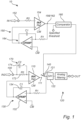
- the circuitry 10 may form part of a medical device, e.g. in the form of a biomedical sensor. As illustrated in Fig. 1 , the circuitry comprises a signal recording input 100, a signal recording amplifier 110, a sampling circuit 120, a feedback integrator 130, a switch 140, and a stimulation artefact detection block 150.
- the circuitry 10 comprises a signal recording input 100 configured to receive a biological electrical signal.
- the biological electrical signal may be construed as any electrical signal that can be acquired by any medical sensor or device configured to acquire electrical signals originating from a biological source.
- the biological electrical signal may be an electrical signal acquired by an electrode or another sensor sensitive to electrical signals, wherein the electrode (or other type of sensor) is configured to detect the biological electrical signal propagating in a nerve, such as a nerve of the central nervous system or the peripheral nervous system.
- the biological electrical signal may be a signal constituting or forming part of electrocardiography, electroencephalography, electromyography, etc.
- the biological electrical signal may be an electrical signal propagating in a biological structure, such as in a nerve, in response to a stimulation of the biological structure.
- the signal recording input 100 may be a node connected to the electrode or other sensor that is configured to acquire the biological electrical signal.
- the signal recording input 100 may thus form an input port connected to the electrode.
- the circuitry 10 may further comprise a current-limiting safety circuit block 170 connected to the signal recording input 100.
- the current-limiting safety circuit block 170 may be arranged between the signal recording input 100 and the signal recording amplifier 110.
- the current-limiting safety circuit block 170 may provide safety of a living being from which the biological electrical signal is acquired.
- the current-limiting safety circuit block 170 may be used with use of an electrode for detecting the biological electrical signal S1, wherein the electrode is connected to the signal recording input 100.
- the current-limiting safety circuit block 170 may comprise a resistor 172.
- the resistor may limit maximum DC and AC currents that can flow through the living being.
- the current-limiting safety circuit block 170 may further comprise a capacitor 174 in parallel to the resistor 172.
- a signal recording amplifier 110 is connected to the signal recording input 100 and configured to provide an amplified biological electrical signal at an output node 111 of the signal recording amplifier 110.
- the signal recording amplifier 110 amplifies the biological electrical signal received at the signal recording input 100 into an amplified biological electrical signal.
- the amplified biological electrical signal may have an increased signal strength compared to the biological electrical signal received at the signal recording input 100, which may facilitate accurate measuring of the biological electrical signal.
- the signal recording amplifier 110 may be an instrumentation amplifier.
- An associated advantage of this configuration may be that an instrumentation amplifier may have an efficient suppression of common mode noise signals, as the instrumentation amplifier offers a high common mode rejection ratio.
- the circuitry 10 further comprises the feedback integrator 130, wherein the feedback integrator 130 is configured to provide a feedback signal into the signal recording amplifier 110.
- the feedback integrator 130 is configured to provide a feedback signal into the signal recording amplifier 110 so as to subtract a DC offset, whereby the DC offset is subtracted or at least reduced in the amplified biological electrical signal.
- the feedback integrator 130 continuously extracts the DC voltage level, e.g. the offset of the input AC signal of the amplified biological electrical signal using the feedback integrator 130.
- the feedback integrator feeds the extracted offset back into the signal recording amplifier 110 so as to subtract the offset from the amplified biological electrical signal in real time.
- the feedback integrator 130 may comprise a resistor at the non-inverting input such that the amplified biological electrical signal passes the resistor before reaching the inverting input.
- the resistor may be tunable so that various high pass cut-off frequencies can be offered.
- the feedback integrator 130 is configured to output a feedback signal into the signal recording amplifier 110.
- the feedback signal may be provided at a non-inverting input of the signal recording amplifier 110.
- the output signal of the signal recording amplifier 110 is free from undesired DC offsets and properly centered around the zero (or common-mode) voltage level.
- Acquisition of the biological electrical signal usually includes a strong DC offset originating from the interface between the electrode and tissue.
- the feedback integrator 130 connected to receive the amplified biological electrical signal may continuously extract the DC voltage level of the biological electrical signal received at the signal recording input 100 and enables this offset to be subtracted from the received biological electrical signal in real time.
- a signal at the output node 111 of the signal recording amplifier 110 may be free from undesired DC offsets and may further be centered around a zero (common mode) voltage level.
- the circuitry 10 further comprises the sampling circuit 120.
- the sampling circuit 120 has an input node 121 connected to the output node 111 of the signal recording amplifier 110.
- the sampling circuit 120 is configured to sample the amplified biological electrical signal.
- the sampling circuit 120 may have a sample-and-hold (S/H) analog block 122 configured to receive the signal at the input node 121 of the sampling circuit 120.
- the S/H block 122 may prohibit signal loss if the incoming signal would be interrupted and reduces distortion levels of the recorded biological electrical signal.
- the S/H block 122 may form a low-pass filter configured to sample and hold the amplified biological electrical signal at the input node 121.
- the circuitry 10 allows for reduction of DC offset of the biological electrical signal. This implies that a high quality recording is provided of the actual biological electrical signal occurring in tissue.
- the circuitry 10 further comprises the switch 140.
- the switch 140 is arranged between the output node 111 of the signal recording amplifier 110 and the input node 121 of the sampling circuit 120.
- the switch 140 is configured to selectively disconnect the output 111 of the signal recording amplifier 110 from the input node 121 of the sampling circuit 120.
- the switch 140 may be used for disconnecting the signal recording amplifier 110 from the sampling circuit 120 whenever a stimulation artefact is detected in the biological electrical signal. This enables preventing any stimulation artefacts from affecting detection of the signal of interest.
- the switch 140 may normally connect the output node 111 of the signal recording amplifier 110 to the input node 121 of the sampling circuit 120.
- the switch 140 enables recording of the biological electrical signal of interest through the sampling circuit 120.
- the switch 140 disconnects the output node 111 of the signal recording amplifier 110 from the sampling circuit 120. This prevents the artefact from entering the sampling circuit 120 and a signal chain for processing the biological electrical signal sampled by the sampling circuit 120.
- the switch 140 reconnects the output node 111 of the signal recording amplifier 110 to the input node 121 of the sampling circuit 120 allowing recording of the biological electrical signal to continue. In this way, any loss of biological electrical signal between stimulation artefacts, such as stimulation pulses, is limited and the recorded signals may be of high quality.
- the sampling circuit 120 may ensure that there is no signal loss when the switch 140 disconnects the output node 111 of the signal recording amplifier 110 from the input node 121 of the sampling circuit 120.
- the S/H block 122 may continue to hold the last recorded signal before interruption by the switch 140, until the switch 140 is reconnected again.
- the feedback integrator 130 is connected to the input port 121 of the sampling circuit 120.
- the switch 140 When the switch 140 is closed, the feedback integrator 130 receives the amplified biological electrical signal for providing feedback to the signal recording amplifier 110. However, when the switch 140 is opened, the feedback integrator 130 is disconnected from the output node 111 of the signal recording amplifier 110.
- the switch 140 is configured to receive a control signal, wherein the control signal S5 is dependent on a detection of a stimulation artefact. Thus, the switch 140 may be opened or closed in dependence of presence of a stimulation artefact in the biological electrical signal.
- the circuitry 10 further comprises the stimulation artefact detection block 150 which is configured to generate the control signal in dependence of detecting a stimulation artefact.
- the stimulation artefact detection block 150 may be configured to detect artefacts having a sufficient amplitude such that recording of the biological electrical signal is affected. Thus, the stimulation artefact detection block 150 may for instance be configured to detect stimulation artefacts based on a threshold signal level being exceeded. It should be realized that even though the stimulation artefact detection block 150 may be specifically used for controlling the switch 140 in dependence of stimulation artefacts, the stimulation artefact detection block 150 is not necessarily limited to a particular cause of an artefact that may affect recording of the biological electrical signal. Thus, if other artefacts cause increase in signal levels, such artefacts may also be detected by the signal artefact detection block 150 and cause control of the switch 140.
- the circuitry 10 allows for disconnecting the signal recording amplifier 110 from the sampling circuit 120, whenever an artefact is detected by the stimulation artefact detection block 150.
- the sampling circuit 120 is only connected to the signal recording amplifier 110 whenever the biological electrical signal does not exhibit an artefact, such that no artefacts or at least no significant artefacts are acquired by the sampling circuit 120.
- the stimulation artefact detection block 150 may comprise a stimulation artefact detection input 152 configured to receive a reference biological electrical signal corresponding to the biological electrical signal to be recorded.
- the stimulation artefact detection block 150 further comprises a stimulation artefact detection amplifier 154 connected to the stimulation artefact detection input 152 and configured to provide an amplified reference biological electrical signal at an output node 156 of the stimulation artefact detection amplifier 154.
- the stimulation artefact detection block 150 may comprise a feedback integrator 164, similar to the feedback integrator 130, implemented in connection to the signal recording amplifier 110.
- the feedback integrator 164 of the stimulation artefact detection block 150 is connected to the output node 156 of the stimulation artefact detection amplifier 154 and configured to provide a feedback signal into the stimulation artefact detection amplifier 154, wherein the feedback integrator is configured to subtract a DC offset from the amplified reference biological electrical signal. This implies that DC offsets may be removed or at least reduced from the reference biological electrical signal.
- the stimulation artefact detection amplifier 154 may form a low-gain block having smaller gain than the signal recording amplifier110. This implies that amplifier saturation stemming from strong pulses due to stimulation artefacts may be avoided.
- the stimulation artefact block 150 may further comprise a comparator circuit 160 having an input node 162 connected to the output node 156 of the stimulation artefact detection amplifier 154 and configured to compare the amplified reference biological electrical signal to a threshold, wherein the comparator circuit 160 is arranged to detect the stimulation artefact based on the comparison of the amplified reference biological electrical signal and the specified threshold.
- a comparator circuit 160 having an input node 162 connected to the output node 156 of the stimulation artefact detection amplifier 154 and configured to compare the amplified reference biological electrical signal to a threshold, wherein the comparator circuit 160 is arranged to detect the stimulation artefact based on the comparison of the amplified reference biological electrical signal and the specified threshold.
- the stimulation artefact detection block 150 may comprise a comparator circuit 160 that compares the reference biological electrical signal to a specified threshold.
- the specified threshold may be set such that as soon as a signal level of the reference biological electrical signal is so large that recording of the biological electrical signal will be affected, the comparator circuit 160 may provide a detection of the stimulation artefact.
- the stimulation artefact detection block 150 may determine that a stimulation artefact is present such that the switch 140 may be appropriately controlled.
- the stimulation artefact detection block 150 may be implemented in other ways, for instance so as to analyze changes within the reference biological electrical signal.
- the reference biological electrical signal may be related in different manners to the biological electrical signal received by the signal recording input 100 such that the reference biological electrical signal corresponds to the biological electrical signal to be recorded.
- the reference biological electrical signal and the biological electrical signal to be recorded may be provided by the same sensor, such as the same electrode.
- the electrode may be connected both to the signal recording input 100 and the stimulation artefact detection input 152, such that the reference biological electrical signal is the same as the biological electrical signal to be recorded.
- different sensors may be used, which may be arranged at locations close to each other, such that the biological electrical signal acquired by a first sensor connected to the signal recording input 100 may be very similar to the reference biological electrical signal acquired by a second sensor connected to the stimulation artefact detection input 152.
- the comparator circuit 160 may be connected to the switch 140 and the switch 140 may be configured to receive the control signal from the comparator circuit 160, wherein the control signal is based on the detection of the stimulation artefact by the comparator circuit 160.
- control signal for controlling the switch 140 may be directly provided from the comparator circuit 160. This allows the control signal to be provided in a simple manner.
- the control signal may control that the switch 140 disconnects the output 111 of the signal recording amplifier 110 from the input node 121 of the sampling circuit 120.
- the control signal provided by the comparator circuit 160 may ensure that no artefacts enter the sampling circuit 120 allowing the biological electrical signal S1 to be recorded with high quality.
- the circuitry 10 may comprise a plurality of signal recording inputs.
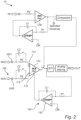
- the signal recording input 100 may comprise a first signal recording input 1001 configured to receive a first biological electrical signal and wherein the circuitry 10 further comprises a second signal recording input 1002 configured to receive a second biological electrical signal.
- the signal recording amplifier 110 may be a differential amplifier having an inverting input 112 and a non-inverting input 113 connected to the first signal recording input 1001 and the second signal recording input 1002, respectively.
- the signal recording amplifier 110 may be configured to amplify a differential signal based on input from two sensors.
- the feedback integrator 130 may be connected to a reference input port 114 of the signal recording amplifier 110 so as to provide the feedback signal into the reference input port 114 of the signal recording amplifier 110 whereby the DC offset may be subtracted from the amplified biological electrical signal.
- the circuitry 10 shown in Fig. 2 may be identical to the circuitry shown in Fig. 1 , except for the signal recording amplifier 110 receiving the second biological electrical signal instead at the non-inverting input 113 and receiving the feedback signal at the reference input port 114, instead of the feedback signal being received at the non-inverting input.
- An associated advantage of this configuration is that it provides differential signal recording of biological electrical signals. This may be used for good attenuation of 50 Hz interference from mains supply.
- circuitry 10 according to a third embodiment will be described.
- the circuitry 10 of the third embodiment corresponds to the circuitry of the second embodiment except for additional components being provided.
- the components that are the same as in the circuitry of the first and second embodiments will not be further described herein.
- the circuitry 10 of the third embodiment has a signal recording input 100 that comprises a first signal recording input 1001 configured to receive a first biological electrical signal and a second signal recording input 1002 configured to receive a second biological electrical signal.
- the first signal recording input 1001 is connected to an inverting input 112 of the signal recording amplifier 110.
- the circuitry 10 of the third embodiment comprises a multiplexer 180.
- the second signal recording input 1002 is connected to a first input of the multiplexer 180.
- the feedback integrator 130 is also connected to output the feedback signal at a second input of the multiplexer 180.
- a common-mode voltage is connected to a third input of the multiplexer 180.
- the multiplexer 180 further comprises a first output connected to the non-inverting input 113 of the signal recording amplifier 110 and a second output connected to the reference input port 114 of the signal recording amplifier 110.
- the multiplexer 180 may be selectively controlled between a first and a second configuration.
- the feedback integrator 130 is connected via the multiplexer 180 to the non-inverting input 113 of the signal recording amplifier 110, and the reference input port 114 of the signal recording amplifier 110 is connected to the common-mode voltage.
- the feedback integrator 130 may be connected via the multiplexer 180 to the reference input port 114 of the signal recording amplifier 110, and the second signal recording input 1002 is connected to the non-inverting input 113 of the signal recording amplifier 110.
- An associated advantage of this configuration is that it provides a tunable and versatile circuitry with a first and a second configuration. Thus, it may be possible to tune the circuitry 10 in line with different applications and intended uses of the circuitry.
- circuitry 10 may be used in the first configuration to allow single-ended recording of the biological electrical signal.
- circuitry 10 may be used in the second configuration to allow differential signal recording of the biological electrical signal.
- the feedback integrator 130 may still be used for providing the DC offset to be subtracted from the amplified biological electrical signal by providing output from the feedback integrator 130 at the reference input port 114 of the signal recording amplifier 110.
- the circuitry 10 shown in Fig. 3 can be tuned or setup such that it can take the form of the circuitry presented in Figure 1 . This may be achieved by connecting the second input of the multiplexer 180 to the first output and the third input of the multiplexer 180 to the second output.
- the circuitry 10 shown in Fig. 3 may alternatively be tuned to take the form of the circuitry presented in Fig. 2 . This may be achieved by connecting the first input of the multiplexer 180 to the first output and the second input of the multiplexer 180 to the second output.
- resistors may be placed in the circuitry 10 at the first and second signal recording input, 1001 and 1002 respectively. This may provide current-limiting safety circuit blocks for both inputs 1001, 1022 in order to increase protection of the human or animal being from which biological electrical signals are acquired.
- circuitry 10 according to a fourth embodiment will be described.
- the circuitry 10 of the fourth embodiment corresponds to the circuitry of the third embodiment except for additional components being provided.
- the components that are the same as in the circuitry of the third embodiment will not be further described herein.
- the signal recording amplifier 100 as shown in the first, second and third embodiments is a first signal recording amplifier 1101
- the feedback integrator 130 is a first feedback integrator 1301
- the switch 140 is a first switch 1401
- the multiplexer 180 is a first multiplexer 1801
- the sampling circuit 120 is a first sampling circuit 1201.
- the first signal recording amplifier 1101, the first feedback integrator 1301, the first switch 1401, the first multiplexer 1801, the first sampling circuit 1201 and a second switch 1402 connected to an output 123 of the first sampling circuit 1201 may form a first signal recording block 11.
Landscapes
- Health & Medical Sciences (AREA)
- Life Sciences & Earth Sciences (AREA)
- Engineering & Computer Science (AREA)
- Physics & Mathematics (AREA)
- Public Health (AREA)
- General Health & Medical Sciences (AREA)
- Veterinary Medicine (AREA)
- Animal Behavior & Ethology (AREA)
- Surgery (AREA)
- Molecular Biology (AREA)
- Medical Informatics (AREA)
- Heart & Thoracic Surgery (AREA)
- Biophysics (AREA)
- Pathology (AREA)
- Biomedical Technology (AREA)
- Signal Processing (AREA)
- Artificial Intelligence (AREA)
- Physiology (AREA)
- Computer Vision & Pattern Recognition (AREA)
- Psychiatry (AREA)
- Neurology (AREA)
- Neurosurgery (AREA)
- Evolutionary Computation (AREA)
- Mathematical Physics (AREA)
- Fuzzy Systems (AREA)
- Power Engineering (AREA)
- Psychology (AREA)
- Measurement And Recording Of Electrical Phenomena And Electrical Characteristics Of The Living Body (AREA)
Abstract
Description
- The present description relates to a circuitry and method for recording a biological electrical signal.
- It is widely accepted by the scientific community that electrical stimulation of specific target brain regions can alleviate symptoms of neurological disorders, such as Parkinson's disease, essential tremor, dystonia, epilepsy, Alzheimer's disease, depression, obsessive-compulsive disorder, Tourette's syndrome, etc. In recent years, the traditional practice of continuously stimulating the brain using static stimulation parameters has shifted to the use of disease biomarkers to determine intensity and timing of stimulation to be used. Biomarkers may thus be used for controlling stimulation such that stimulation may be provided only when required within a certain period of time. This may allow side effects of the stimulation to be reduced or minimized.
- It would thus be desired to have a system allowing continuous monitoring of biological electrical signals such that disease biomarkers may be continuously identified. Hence, the concept of concurrent recording and stimulation of biological electrical signals is becoming more and more important in bidirectional stimulation and recording applications.
- However, stimulation pulses create interference with readout circuits for recording biological electrical signals. The stimulation pulses may appear as artefacts masking the underlying biological electrical signal (such as a neural signal) and making concurrent recording and stimulation of biological electrical signals a challenge.
- The artefacts may often be misclassified as action potentials by detection algorithms, and subsequent action potentials cannot be recorded until an amplifier for amplifying a sensed biological electrical signal has recovered from saturation. Thus, rejection or at least reduction of artefacts due to stimulation may be highly beneficial for providing improved accurate recordings of the bioelectrical signals of interest.
- It is an objective to, at least partly, mitigate, alleviate, or eliminate one or more of the above-identified deficiencies in the art singly or in any combination. In particular, it is an objective to provide recording of biological electrical signal while avoiding or reducing impact of stimulation signals on the recording of the biological electrical signals.
- This and other objectives are at least partly met by the invention as defined in the independent claims. Preferred embodiments are set out in the dependent claims.
- According to a first aspect, there is provided a circuitry for recording a biological electrical signal. The circuitry comprises a signal recording input configured to receive the biological electrical signal, a signal recording amplifier connected to the signal recording input and configured to provide an amplified biological electrical signal at an output node of the signal recording amplifier, a sampling circuit having an input node connected to the output node of the amplifier and configured to sample the amplified biological electrical signal, a feedback integrator connected to the input node of the sampling circuit and configured to provide a feedback signal into the signal recording amplifier, wherein the feedback integrator is configured to subtract a direct current (DC) offset from the amplified biological electrical signal. The circuitry further comprises a switch configured to selectively disconnect the output of the signal recording amplifier from the input node of the sampling circuit and a stimulation artefact detection block configured to detect a stimulation artefact, wherein the switch is configured to receive a control signal for controlling the switch, wherein the control signal is dependent on detection, by the stimulation artefact detection block, of a stimulation artefact affecting recording of the biological electrical signal.
- Within the context of this disclosure the wording "biological electrical signal" should be construed as any electrical signal that can be acquired by any medical sensor or device configured to acquire electrical signals stemming from a biological source. The biological electrical signal may be an electrical signal acquired by an electrode or another sensor sensitive to electrical signals, wherein the electrode (or other type of sensor) is configured to detect the biological electrical signal propagating in a nerve, such as a nerve of the central nervous system or the peripheral nervous system. The biological electrical signal may be a signal constituting or forming part of electrocardiography, electroencephalography, electromyography, etc.
- The circuitry of the first aspect allows for the circuit to disconnect the signal recording amplifier from the sampling circuit, whenever an artefact is detected by the stimulation artefact detection block. Put differently, the sampling circuit is only connected to the signal recording amplifier whenever the biological electrical signal does not exhibit an artefact, such that no artefacts or at least no significant artefacts are acquired by the sampling circuit.
- The stimulation artefact detection block is configured to detect a stimulation artefact. Thus, the stimulation artefact detection block is able to identify timing of artefacts being present in the biological electrical signal received at the signal recording input. The switch is controlled such that, when the stimulation artefact detection block detects a stimulation artefact, the switch may disconnect the signal recording amplifier from the sampling circuit.
- The stimulation artefact detection block may be configured to detect artefacts having a sufficient amplitude such that recording of the biological electrical signal is affected. Thus, the stimulation artefact detection block may for instance be configured to detect stimulation artefacts based on a threshold signal level being exceeded. It should be realized that even though the stimulation artefact detection block may be specifically used for controlling the switch in dependence of stimulation artefacts, the stimulation artefact detection block is not necessarily limited to a particular cause of an artefact that may affect recording of the biological electrical signal. Thus, if other artefacts cause increase in signal levels, such artefacts may also be detected by the signal artefact detection block and cause control of the switch.
- The switch may be used for disconnecting the signal recording amplifier from the sampling circuit whenever a stimulation artefact due to simultaneous stimulation is detected. This enables preventing any stimulation artefacts from contaminating the signal of interest. More specifically, between stimulation pulses, the switch may normally connect the output node of the signal recording amplifier to the sampling circuit. Thus, the switch enables recording the biological electrical signal of interest through the sampling circuit. However, before the stimulation pulse affects the recording of biological electrical signal, the switch disconnects the output node of the signal recording amplifier from the sampling circuit, preventing the artefact from entering the sampling circuit and a signal chain for processing the biological electrical signal sampled by the sampling circuit. At end of a stimulation pulse, the switch reconnects the output node of the signal recording amplifier to the sampling circuit allowing recording of the biological electrical signal to continue until a next stimulation pulse arrives. In this way, any loss of biological electrical signal between the stimulation pulses is limited and the recorded signals are of high quality.
- The circuitry also allows for reduction of DC offset of the biological electrical signal. This implies that a high quality recording of the actual biological electrical signal occurring in tissue. Acquisition of the biological electrical signal usually includes a strong DC offset stemming from the interface between the electrode and tissue. The feedback integrator connected to the input node of the sampling circuit may continuously extract the DC voltage level of the biological electrical signal received at the signal recording input and enables this offset to be subtracted from the received biological electrical signal in real time. As a result, a signal at the output node of the signal recording amplifier may be free from undesired DC offsets and may further be centered around a zero (common mode) voltage level.
- The stimulation artefact detection block may further comprise a stimulation artefact detection input configured to receive a reference biological electrical signal corresponding to the biological electrical signal to be recorded and a stimulation artefact detection amplifier connected to the stimulation artefact detection input and configured to provide an amplified reference biological electrical signal at an output node of the stimulation artefact detection amplifier. The stimulation artefact block may further comprise a comparator circuit having an input node connected to the output node of the stimulation artefact detection amplifier and configured to compare the amplified reference biological electrical signal to a threshold, wherein the comparator circuit is arranged to detect the stimulation artefact based on the comparison of the amplified reference biological electrical signal and the specified threshold.
- Thus, the stimulation artefact detection block may comprise a comparator circuit that compares the reference biological electrical signal to a specified threshold. The specified threshold may be set such that as soon as a signal level of the reference biological electrical signal is so large that recording of the biological electrical signal will be affected, the comparator circuit may provide a detection of the stimulation artefact. Thus, if the reference biological electrical signal exceeds the specified threshold the stimulation artefact detection block may determine that a stimulation artefact is present such that the switch may be appropriately controlled.
- The use of the specified threshold may allow a simple comparison to be made by the comparator circuit. However, it should be realized that the stimulation artefact detection block may be implemented in other ways, for instance so as to analyze changes within the reference biological electrical signal.
- It should be realized that the reference biological electrical signal may be related in different manners to the biological electrical signal received by the signal recording input such that the reference biological electrical signal corresponds to the biological electrical signal to be recorded. For instance, the reference biological electrical signal and the biological electrical signal to be recorded may be provided by the same sensor, such as the same electrode. Thus, the electrode may be connected both to the signal recording input and the stimulation artefact detection input, such that the reference biological electrical signal is the same as the biological electrical signal to be recorded. However, according to an alternative, different sensors may be used, which may be arranged at locations close to each other, such that the biological electrical signal acquired by a first sensor connected to the signal recording input may be very similar to the reference biological electrical signal acquired by a second sensor connected to the stimulation artefact detection input.
- Furthermore, the stimulation artefact detection amplifier may comprise a feedback integrator connected to the input node of the comparator and configured to provide a feedback signal into the stimulation artefact detection amplifier, wherein the feedback integrator is configured to subtract a DC offset from the amplified reference biological electrical signal.
- This implies that DC offsets may be removed or at least reduced from the reference biological electrical signal.
- The comparator circuit may be connected to the switch and the switch may be configured to receive the control signal from the comparator circuit, wherein the control signal is based on the detection of the stimulation artefact by the comparator circuit.
- Thus, the control signal for controlling the switch may be directly provided from the comparator circuit. This allows the control signal to be provided in a simple manner.
- The control signal may control that the switch disconnects the output of the signal recording amplifier from the input node of the sampling circuit. Thus, the control signal provided by the comparator circuit may ensure that no artefacts enter the sampling circuit allowing the biological electrical signal to be recorded with high quality.
- The circuitry may further comprise a current-limiting safety circuit block between the signal recording input and the signal recording amplifier.
- This implies that safety of a living being from which the biological electrical signal is acquired increases for the circuitry. In particular, it should be realized that the current-limiting safety circuit block may be used with use of an electrode for detecting the biological electrical signal, wherein the electrode is connected to the signal recording input.
- The current-limiting safety circuit block may comprise a resistor. The resistor may limit maximum DC and alternating current (AC) currents that can flow through the living being.
- The current-limiting safety circuit block may further comprise a capacitor in parallel to the resistor. The capacitor may decrease an impact of the resistor on a recording performance at high frequencies.
- The sampling circuit may comprise a low-pass filter configured to sample and hold the amplified biological electrical signal at the input node.
- An associated advantage of this configuration is that the sampling circuit may ensure that there is no signal loss at the input node of the sampling circuit when the switch disconnects the output of the signal recording amplifier from the input node of the sampling circuit. When the switch disconnects the output of the signal recording amplifier from the input node of the sampling circuit, the sampling circuit may continue the hold the last recorded signal before interruption by the switch, until the switch is reconnected again.
- The feedback integrator may comprise an operational amplifier and a feedback capacitor connected between an output of the operational amplifier and an inverting input of the operational amplifier for providing negative feedback to the operational amplifier.
- An associated advantage of this configuration is that an operational amplifier may have a low power consumption, such that the circuitry may provide subtraction of DC offset in a power efficient manner. The operational amplifier may also be implemented in a compact manner such that a small space or footprint may be needed for incorporation of the operational amplifier in the circuitry.
- The signal recording amplifier may be an instrumentation amplifier.
- An associated advantage of this configuration is that an instrumentation amplifier may have an efficient suppression of common mode noise signals, as the instrumentation amplifier offers a high common mode rejection ratio.
- An additional associated advantage of this configuration is that an instrumentation amplifier may have a low power consumption, such that the circuitry may provide subtraction of DC offset in a power efficient manner. The instrumentation amplifier may also be implemented in a compact manner such that a small space or footprint may be needed for incorporation of the instrumentation amplifier in the circuitry.
- It should however be realized that the signal recording amplifier may alternatively be implemented as a differential amplifier.
- The signal recording input may be a first signal recording input configured to receive a first biological electrical signal and wherein the circuitry further comprises a second signal recording input configured to receive a second biological electrical signal, wherein the signal recording amplifier may be a differential amplifier having an inverting input and a non-inverting input connected to the first signal recording input and the second signal recording input, respectively, wherein the feedback integrator may be connected to a reference input port of the signal recording amplifier.
- An associated advantage of this configuration is that it provides differential signal recording of the biological electrical signal. This may be used for good attenuation of 50 Hz interference from mains supply.
- The signal recording input may be a first signal recording input configured to receive a first biological electrical signal and wherein the first signal recording input may be connected to an inverting input of the signal recording amplifier, wherein the circuitry further comprises a second signal recording input configured to receive a second biological electrical signal, and wherein the circuitry further comprises a multiplexer, wherein the multiplexer is connected to the feedback integrator, and the multiplexer may be selectively controlled between a first and a second configuration.
- In the first configuration, the feedback integrator may be connected via the multiplexer to a non-inverting input of the signal recording amplifier, and a reference input port of the signal recording amplifier is connected to a common-mode voltage. In the second configuration, the feedback integrator may be connected via the multiplexer to the reference input port of the signal recording amplifier, and the second signal recording input is connected to the non-inverting input of the signal recording amplifier.
- An associated advantage of this configuration is that it provides a tunable and versatile circuitry with a first and a second configuration. Thus, it may be possible to tune the circuitry in line with different applications and intended uses of the circuitry.
- In particular, the circuitry may be used in the first configuration to allow single-ended recording of the biological electrical signal.
- In addition, the circuitry may be used in the second configuration to allow differential signal recording of the biological electrical signal. The feedback integrator may still be used for providing the DC offset to be subtracted from the amplified biological electrical signal by providing output from the feedback integrator at the reference input port of the signal recording amplifier.
- The signal recording amplifier may be a first signal recording amplifier, the feedback integrator may be a first feedback integrator, the switch may be a first switch, the multiplexer may be a first multiplexer and the sampling circuit may be a first sampling circuit, wherein the first signal recording amplifier, the first feedback integrator, the first switch, the first multiplexer, the first sampling circuit and a second switch connected to an output of the first sampling circuit may form a first signal recording block, wherein the circuitry further comprises a second signal recording block comprising a second signal recording amplifier, a second feedback integrator, a second multiplexer, a second sampling circuit, a third switch configured to selectively disconnect the output of the second signal recording amplifier from an input node of the second sampling circuit, and a fourth switch connected to an output of the second sampling circuit, wherein the first and second switches may be configured to be de-activated in dependence of the detection, by the stimulation artefact detection block, of a signal level of the stimulation artefact being above a first threshold and the third and fourth switches are configured to be activated in dependence of the detection, by the stimulation artefact detection block, of the signal level of the stimulation artefact being above the first threshold.
- An associated advantage of this configuration is that it allows signal loss during a monophasic stimulation to be avoided or reduced, as the configuration allows for continued acquirement of the biological electrical signal, even during a monophasic stimulation.
- The second signal recording block may be activated to provide recording of the biological electrical signal during presence of the stimulation artefact.
- The stimulation artefact detection block may further comprise a delay circuit for delaying a second control signal controlling the second switch in relation to a first control signal controlling the first switch and delaying a fourth control signal controlling the fourth switch in relation to a third control signal controlling the third switch.
- An associated advantage of this configuration is that the delay ensures that feedback AC-coupled loops provided by the feedback integrators are allowed some time in order to properly settle before a signal is output from a respective sampling circuit. This may prevent any switching artefact from entering a signal chain for processing the biological electrical signals.
- The circuitry may further comprise a third signal recording block comprising a third signal recording amplifier, a third feedback integrator, a third multiplexer, a third sampling circuit, a fifth switch configured to selectively disconnect the output of the third signal recording amplifier from an input node of the third sampling circuit, and a sixth switch connected to an output of the third sampling circuit, wherein the fifth and sixth switches may be configured to be activated in dependence of the detection, by the stimulation artefact detection block, of the signal level of the stimulation artefact being below a second threshold, lower than the first threshold.
- An associated advantage of this configuration is it allows signal loss during a biphasic stimulation to be avoided or reduced, as the configuration allows for continued acquirement of the biological electrical signal, even during a stimulation pulse with two phases.
- The second signal recording block may be activated to provide recording of the biological electrical signal during presence of a first phase of the stimulation artefact. The third signal recording block may be activated to provide recording of the biological electrical signal during presence of a second phase of the stimulation artefact.
- According to a second aspect, there is provided an apparatus for recording a biological electrical signal, said apparatus comprising one or more electrodes for sensing the biological electrical signal and the circuitry according to the first aspect.
- Effects and features of this second aspect are largely analogous to those described above in connection with the first aspect. Embodiments mentioned in relation to the second aspect are largely compatible with the first aspects.
- Thus, the circuitry may be incorporated in an apparatus for recording a biological electrical signal. The apparatus may comprise electrodes for sensing the biological electrical signal and the circuitry for recording the biological electrical signal while avoiding or reducing impact of a stimulation artefact on the recording of the biological electrical signal.
- The apparatus may further comprise a stimulation unit for providing a stimulation signal in a biological structure, e.g., in a nerve, such as a nerve in the central nervous system or the peripheral nervous system, or in a body region, such as a brain region, for stimulating activity of the biological electrical signal. Thanks to the circuitry being configured to avoid or reduce impact of stimulation artefacts, the apparatus is thus particularly suited for providing stimulation and simultaneously recording biological electrical signals.
- According to a third aspect, there is provided a method for recording a biological electrical signal. The method comprises the steps of receiving, by a signal recording input, the biological electrical signal, amplifying, by a signal recording amplifier connected to the signal recording input, the biological electrical signal, sampling, by a sampling circuit having an input node connected to an output of the signal recording amplifier, the amplified biological electrical signal, providing, a feedback signal into the signal recording amplifier, wherein the feedback signal is created by subtracting a direct current (DC) offset, from the amplified biological electrical signal, using a feedback integrator connected to the input node of the sampling circuit, receiving, a control signal which is dependent of the detection of a stimulation artefact affecting recording of the biological electrical signal, in response to receiving the control signal, selectively disconnecting the output of the signal recording amplifier from the input node of the sampling circuit using a switch and recording, the biological electrical signal, when the switch connects the output of the signal recording amplifier to the input node of the sampling circuit for output of the amplified biological signal with a subtracted DC offset.
- Effects and features of this third aspect are largely analogous to those described above in connection with the first and second aspects. Embodiments mentioned in relation to the third aspect are largely compatible with the first and second aspects.
- The method allows recording the biological electrical signal while avoiding or reducing impact of a stimulation artefact on the recording of the biological electrical signal.
- The method may further comprise the steps of generating the control signal, wherein said generating comprises receiving, by a stimulation artefact detection input, a reference biological signal corresponding to the biological signal to be recorded, amplifying, by a stimulation artefact detection amplifier connected to the stimulation artefact detection input, the reference biological electrical signal, comparing the amplified reference biological electrical signal to a specified threshold, generating the control signal in dependence on the comparison of the amplified biological electrical signal and the specified threshold.
- Thus, the control signal for controlling the switch may be directly provided from the comparator circuit. This allows the control signal to be provided in a simple manner.
- The method may further comprise switching, using one or more multiplexers, between two or more different circuit configurations for single-ended or differential recording of the biological electrical signal.
- This allows tunable and versatile use of the method for recording the biological electrical signal.
- The above, as well as additional objects, features, and advantages of the present description, will be better understood through the following illustrative and non-limiting detailed description, with reference to the appended drawings. In the drawings like reference numerals will be used for like elements unless stated otherwise.
-
Fig. 1 is a schematic view of a circuitry for recording a biological electrical signal according to a first embodiment. -
Fig. 2 is a schematic view a circuitry for recording a biological electrical signal according to a second embodiment. -
Fig. 3 is a schematic view of a circuitry for recording a biological electrical signal according to a third embodiment. -
Fig. 4 is a schematic view of a circuitry for recording a biological electrical signal according to a fourth embodiment. -
Fig. 5 is a schematic view of a circuitry for recording a biological electrical signal according to a fifth embodiment. -
Fig. 6 is a schematic view of an apparatus for recording a biological electrical signal. -
Fig. 7 is a flow chart of a method for recording a biological electrical signal. - In the following, a
circuitry 10 for recording a biological electrical signal according to several different embodiments will be described in connection withFigures 1-6 . Thecircuitry 10 may form part of a medical device, e.g. in the form of a biomedical sensor. As illustrated inFig. 1 , the circuitry comprises asignal recording input 100, asignal recording amplifier 110, asampling circuit 120, afeedback integrator 130, aswitch 140, and a stimulationartefact detection block 150. - Referring now to
Fig. 1 , thecircuitry 10 comprises asignal recording input 100 configured to receive a biological electrical signal. The biological electrical signal may be construed as any electrical signal that can be acquired by any medical sensor or device configured to acquire electrical signals originating from a biological source. Furthermore, the biological electrical signal may be an electrical signal acquired by an electrode or another sensor sensitive to electrical signals, wherein the electrode (or other type of sensor) is configured to detect the biological electrical signal propagating in a nerve, such as a nerve of the central nervous system or the peripheral nervous system. The biological electrical signal may be a signal constituting or forming part of electrocardiography, electroencephalography, electromyography, etc. In particular, the biological electrical signal may be an electrical signal propagating in a biological structure, such as in a nerve, in response to a stimulation of the biological structure. - The
signal recording input 100 may be a node connected to the electrode or other sensor that is configured to acquire the biological electrical signal. Thesignal recording input 100 may thus form an input port connected to the electrode. - The
circuitry 10 may further comprise a current-limitingsafety circuit block 170 connected to thesignal recording input 100. The current-limitingsafety circuit block 170 may be arranged between thesignal recording input 100 and thesignal recording amplifier 110. The current-limitingsafety circuit block 170 may provide safety of a living being from which the biological electrical signal is acquired. In particular, it should be realized that the current-limitingsafety circuit block 170 may be used with use of an electrode for detecting the biological electrical signal S1, wherein the electrode is connected to thesignal recording input 100. The current-limitingsafety circuit block 170 may comprise aresistor 172. The resistor may limit maximum DC and AC currents that can flow through the living being. The current-limitingsafety circuit block 170 may further comprise acapacitor 174 in parallel to theresistor 172. Thecapacitor 174 may decrease an impact of theresistor 172 on a recording performance at high frequencies. Thecapacitor 174 may mainly be useful when a bioimpedance signal is to be recorded and may therefore be associated with a switch for disconnecting thecapacitor 174, which may allow the current-limitingsafety circuit block 170 to be adapted to a type of biological electrical signal being detected. - A
signal recording amplifier 110 is connected to thesignal recording input 100 and configured to provide an amplified biological electrical signal at anoutput node 111 of thesignal recording amplifier 110. - The
signal recording amplifier 110 amplifies the biological electrical signal received at thesignal recording input 100 into an amplified biological electrical signal. The amplified biological electrical signal may have an increased signal strength compared to the biological electrical signal received at thesignal recording input 100, which may facilitate accurate measuring of the biological electrical signal. Thesignal recording amplifier 110 may be an instrumentation amplifier. - An associated advantage of this configuration may be that an instrumentation amplifier may have an efficient suppression of common mode noise signals, as the instrumentation amplifier offers a high common mode rejection ratio.
- An additional associated advantage of this configuration is that an instrumentation amplifier may have a low power consumption, such that the
circuitry 10 may provide subtraction of DC offset in a power efficient manner. The instrumentation amplifier may also be implemented in a compact manner such that a small space or footprint may be needed for incorporation of the instrumentation amplifier in the circuitry. - The
circuitry 10 further comprises thefeedback integrator 130, wherein thefeedback integrator 130 is configured to provide a feedback signal into thesignal recording amplifier 110. Thefeedback integrator 130 is configured to provide a feedback signal into thesignal recording amplifier 110 so as to subtract a DC offset, whereby the DC offset is subtracted or at least reduced in the amplified biological electrical signal. Thefeedback integrator 130 continuously extracts the DC voltage level, e.g. the offset of the input AC signal of the amplified biological electrical signal using thefeedback integrator 130. The feedback integrator feeds the extracted offset back into thesignal recording amplifier 110 so as to subtract the offset from the amplified biological electrical signal in real time. - The
feedback integrator 130 may be an analog feedback integrator. Thefeedback integrator 130 may comprise anoperational amplifier 132 having an inverting input connected to receive the amplified biological electrical signal and a non-inverting input connected to a common-mode voltage. Thefeedback integrator 130 further comprises afeedback capacitor 134 connected between an output of theoperational amplifier 132 and an inverting input of the operational amplifier for providing negative feedback to theoperational amplifier 132. - An associated advantage of this configuration is that an operational amplifier may have a low power consumption, such that the
circuitry 10 may provide subtraction of DC offset in a power efficient manner. Theoperational amplifier 132 may also be implemented in a compact manner such that a small space or footprint may be needed for incorporation of the operational 132 amplifier in thecircuitry 10. - The
feedback integrator 130 may comprise a resistor at the non-inverting input such that the amplified biological electrical signal passes the resistor before reaching the inverting input. The resistor may be tunable so that various high pass cut-off frequencies can be offered. - The
feedback integrator 130 is configured to output a feedback signal into thesignal recording amplifier 110. As shown inFig. 1 , the feedback signal may be provided at a non-inverting input of thesignal recording amplifier 110. As a result of this, the output signal of thesignal recording amplifier 110 is free from undesired DC offsets and properly centered around the zero (or common-mode) voltage level. Acquisition of the biological electrical signal usually includes a strong DC offset originating from the interface between the electrode and tissue. Thefeedback integrator 130 connected to receive the amplified biological electrical signal may continuously extract the DC voltage level of the biological electrical signal received at thesignal recording input 100 and enables this offset to be subtracted from the received biological electrical signal in real time. As a result, a signal at theoutput node 111 of thesignal recording amplifier 110 may be free from undesired DC offsets and may further be centered around a zero (common mode) voltage level. - The
circuitry 10 further comprises thesampling circuit 120. Thesampling circuit 120 has aninput node 121 connected to theoutput node 111 of thesignal recording amplifier 110. Thesampling circuit 120 is configured to sample the amplified biological electrical signal. - The
sampling circuit 120 may have a sample-and-hold (S/H)analog block 122 configured to receive the signal at theinput node 121 of thesampling circuit 120. The S/H block 122 may prohibit signal loss if the incoming signal would be interrupted and reduces distortion levels of the recorded biological electrical signal. - The S/H block 122 may form a low-pass filter configured to sample and hold the amplified biological electrical signal at the
input node 121. Thus thecircuitry 10 allows for reduction of DC offset of the biological electrical signal. This implies that a high quality recording is provided of the actual biological electrical signal occurring in tissue. - The
circuitry 10 further comprises theswitch 140. Theswitch 140 is arranged between theoutput node 111 of thesignal recording amplifier 110 and theinput node 121 of thesampling circuit 120. Theswitch 140 is configured to selectively disconnect theoutput 111 of thesignal recording amplifier 110 from theinput node 121 of thesampling circuit 120. Theswitch 140 may be used for disconnecting thesignal recording amplifier 110 from thesampling circuit 120 whenever a stimulation artefact is detected in the biological electrical signal. This enables preventing any stimulation artefacts from affecting detection of the signal of interest. - More specifically, the
switch 140 may normally connect theoutput node 111 of thesignal recording amplifier 110 to theinput node 121 of thesampling circuit 120. Thus, theswitch 140 enables recording of the biological electrical signal of interest through thesampling circuit 120. However, in case of a stimulation artefact being present in the biological electrical signal and affecting the recording of biological electrical signal, theswitch 140 disconnects theoutput node 111 of thesignal recording amplifier 110 from thesampling circuit 120. This prevents the artefact from entering thesampling circuit 120 and a signal chain for processing the biological electrical signal sampled by thesampling circuit 120. At end of a stimulation artefact, theswitch 140 reconnects theoutput node 111 of thesignal recording amplifier 110 to theinput node 121 of thesampling circuit 120 allowing recording of the biological electrical signal to continue. In this way, any loss of biological electrical signal between stimulation artefacts, such as stimulation pulses, is limited and the recorded signals may be of high quality. - Thanks to the
sampling circuit 120 having the S/H block 122 connected to theinput node 121, thesampling circuit 120 may ensure that there is no signal loss when theswitch 140 disconnects theoutput node 111 of thesignal recording amplifier 110 from theinput node 121 of thesampling circuit 120. When theswitch 140 disconnects theoutput node 111 of thesignal recording amplifier 110 from theinput node 121 of thesampling circuit 120, the S/H block 122 may continue to hold the last recorded signal before interruption by theswitch 140, until theswitch 140 is reconnected again. - The
feedback integrator 130 is connected to theinput port 121 of thesampling circuit 120. When theswitch 140 is closed, thefeedback integrator 130 receives the amplified biological electrical signal for providing feedback to thesignal recording amplifier 110. However, when theswitch 140 is opened, thefeedback integrator 130 is disconnected from theoutput node 111 of thesignal recording amplifier 110. - The
switch 140 is configured to receive a control signal, wherein the control signal S5 is dependent on a detection of a stimulation artefact. Thus, theswitch 140 may be opened or closed in dependence of presence of a stimulation artefact in the biological electrical signal. Thecircuitry 10 further comprises the stimulationartefact detection block 150 which is configured to generate the control signal in dependence of detecting a stimulation artefact. - The stimulation
artefact detection block 150 is configured to detect stimulation artefacts in the biological electrical signal. Thus, the stimulationartefact detection block 150 is able to identify timing of artefacts being present in the biological electrical signal received at thesignal recording input 100. Theswitch 140 is controlled such that, when the stimulationartefact detection block 150 detects a stimulation artefact, theswitch 140 may disconnect thesignal recording amplifier 110 from thesampling circuit 120. - The stimulation
artefact detection block 150 may be configured to detect artefacts having a sufficient amplitude such that recording of the biological electrical signal is affected. Thus, the stimulationartefact detection block 150 may for instance be configured to detect stimulation artefacts based on a threshold signal level being exceeded. It should be realized that even though the stimulationartefact detection block 150 may be specifically used for controlling theswitch 140 in dependence of stimulation artefacts, the stimulationartefact detection block 150 is not necessarily limited to a particular cause of an artefact that may affect recording of the biological electrical signal. Thus, if other artefacts cause increase in signal levels, such artefacts may also be detected by the signalartefact detection block 150 and cause control of theswitch 140. Thecircuitry 10 allows for disconnecting thesignal recording amplifier 110 from thesampling circuit 120, whenever an artefact is detected by the stimulationartefact detection block 150. Put differently, thesampling circuit 120 is only connected to thesignal recording amplifier 110 whenever the biological electrical signal does not exhibit an artefact, such that no artefacts or at least no significant artefacts are acquired by thesampling circuit 120. - The stimulation
artefact detection block 150 may comprise a stimulationartefact detection input 152 configured to receive a reference biological electrical signal corresponding to the biological electrical signal to be recorded. The stimulationartefact detection block 150 further comprises a stimulationartefact detection amplifier 154 connected to the stimulationartefact detection input 152 and configured to provide an amplified reference biological electrical signal at an output node 156 of the stimulationartefact detection amplifier 154. - Furthermore, the stimulation
artefact detection block 150 may comprise afeedback integrator 164, similar to thefeedback integrator 130, implemented in connection to thesignal recording amplifier 110. Thefeedback integrator 164 of the stimulationartefact detection block 150 is connected to the output node 156 of the stimulationartefact detection amplifier 154 and configured to provide a feedback signal into the stimulationartefact detection amplifier 154, wherein the feedback integrator is configured to subtract a DC offset from the amplified reference biological electrical signal. This implies that DC offsets may be removed or at least reduced from the reference biological electrical signal. - The stimulation
artefact detection amplifier 154 may form a low-gain block having smaller gain than the signal recording amplifier110. This implies that amplifier saturation stemming from strong pulses due to stimulation artefacts may be avoided. - The
stimulation artefact block 150 may further comprise acomparator circuit 160 having an input node 162 connected to the output node 156 of the stimulationartefact detection amplifier 154 and configured to compare the amplified reference biological electrical signal to a threshold, wherein thecomparator circuit 160 is arranged to detect the stimulation artefact based on the comparison of the amplified reference biological electrical signal and the specified threshold. - Thus, the stimulation
artefact detection block 150 may comprise acomparator circuit 160 that compares the reference biological electrical signal to a specified threshold. The specified threshold may be set such that as soon as a signal level of the reference biological electrical signal is so large that recording of the biological electrical signal will be affected, thecomparator circuit 160 may provide a detection of the stimulation artefact. Thus, if the reference biological electrical signal exceeds the specified threshold the stimulationartefact detection block 150 may determine that a stimulation artefact is present such that theswitch 140 may be appropriately controlled. - The use of the specified threshold may allow a simple comparison to be made by the
comparator circuit 160. However, it should be realized that the stimulationartefact detection block 150 may be implemented in other ways, for instance so as to analyze changes within the reference biological electrical signal. - It should be realized that the reference biological electrical signal may be related in different manners to the biological electrical signal received by the
signal recording input 100 such that the reference biological electrical signal corresponds to the biological electrical signal to be recorded. For instance, the reference biological electrical signal and the biological electrical signal to be recorded may be provided by the same sensor, such as the same electrode. Thus, the electrode may be connected both to thesignal recording input 100 and the stimulationartefact detection input 152, such that the reference biological electrical signal is the same as the biological electrical signal to be recorded. - However, according to an alternative, different sensors may be used, which may be arranged at locations close to each other, such that the biological electrical signal acquired by a first sensor connected to the
signal recording input 100 may be very similar to the reference biological electrical signal acquired by a second sensor connected to the stimulationartefact detection input 152. - The
comparator circuit 160 may be connected to theswitch 140 and theswitch 140 may be configured to receive the control signal from thecomparator circuit 160, wherein the control signal is based on the detection of the stimulation artefact by thecomparator circuit 160. - Thus, the control signal for controlling the
switch 140 may be directly provided from thecomparator circuit 160. This allows the control signal to be provided in a simple manner. - The control signal may control that the
switch 140 disconnects theoutput 111 of thesignal recording amplifier 110 from theinput node 121 of thesampling circuit 120. Thus, the control signal provided by thecomparator circuit 160 may ensure that no artefacts enter thesampling circuit 120 allowing the biological electrical signal S1 to be recorded with high quality. - Referring now to
Fig. 2 , thecircuitry 10 according to a second embodiment may comprise a plurality of signal recording inputs. As such, thesignal recording input 100 may comprise a firstsignal recording input 1001 configured to receive a first biological electrical signal and wherein thecircuitry 10 further comprises a secondsignal recording input 1002 configured to receive a second biological electrical signal. Thesignal recording amplifier 110 may be a differential amplifier having an invertinginput 112 and anon-inverting input 113 connected to the firstsignal recording input 1001 and the secondsignal recording input 1002, respectively. Thus, thesignal recording amplifier 110 may be configured to amplify a differential signal based on input from two sensors. Further, thefeedback integrator 130 may be connected to areference input port 114 of thesignal recording amplifier 110 so as to provide the feedback signal into thereference input port 114 of thesignal recording amplifier 110 whereby the DC offset may be subtracted from the amplified biological electrical signal. - The
circuitry 10 shown inFig. 2 may be identical to the circuitry shown inFig. 1 , except for thesignal recording amplifier 110 receiving the second biological electrical signal instead at thenon-inverting input 113 and receiving the feedback signal at thereference input port 114, instead of the feedback signal being received at the non-inverting input. - An associated advantage of this configuration is that it provides differential signal recording of biological electrical signals. This may be used for good attenuation of 50 Hz interference from mains supply.
- Referring now to
Fig. 3 , thecircuitry 10 according to a third embodiment will be described. Thecircuitry 10 of the third embodiment corresponds to the circuitry of the second embodiment except for additional components being provided. The components that are the same as in the circuitry of the first and second embodiments will not be further described herein. - Like the circuitry of the second embodiment, the
circuitry 10 of the third embodiment has asignal recording input 100 that comprises a firstsignal recording input 1001 configured to receive a first biological electrical signal and a secondsignal recording input 1002 configured to receive a second biological electrical signal. The firstsignal recording input 1001 is connected to an invertinginput 112 of thesignal recording amplifier 110. - However, in contrast to the circuitry of the second embodiment, the
circuitry 10 of the third embodiment comprises amultiplexer 180. The secondsignal recording input 1002 is connected to a first input of themultiplexer 180. Thefeedback integrator 130 is also connected to output the feedback signal at a second input of themultiplexer 180. Further, a common-mode voltage is connected to a third input of themultiplexer 180. Themultiplexer 180 further comprises a first output connected to thenon-inverting input 113 of thesignal recording amplifier 110 and a second output connected to thereference input port 114 of thesignal recording amplifier 110. - The
multiplexer 180 may be selectively controlled between a first and a second configuration. - In the first configuration, the
feedback integrator 130 is connected via themultiplexer 180 to thenon-inverting input 113 of thesignal recording amplifier 110, and thereference input port 114 of thesignal recording amplifier 110 is connected to the common-mode voltage. In the second configuration, thefeedback integrator 130 may be connected via themultiplexer 180 to thereference input port 114 of thesignal recording amplifier 110, and the secondsignal recording input 1002 is connected to thenon-inverting input 113 of thesignal recording amplifier 110. - An associated advantage of this configuration is that it provides a tunable and versatile circuitry with a first and a second configuration. Thus, it may be possible to tune the
circuitry 10 in line with different applications and intended uses of the circuitry. - In particular, the
circuitry 10 may be used in the first configuration to allow single-ended recording of the biological electrical signal. - In addition, the
circuitry 10 may be used in the second configuration to allow differential signal recording of the biological electrical signal. Thefeedback integrator 130 may still be used for providing the DC offset to be subtracted from the amplified biological electrical signal by providing output from thefeedback integrator 130 at thereference input port 114 of thesignal recording amplifier 110. - More specifically, the
circuitry 10 shown inFig. 3 can be tuned or setup such that it can take the form of the circuitry presented inFigure 1 . This may be achieved by connecting the second input of themultiplexer 180 to the first output and the third input of themultiplexer 180 to the second output. Thecircuitry 10 shown inFig. 3 may alternatively be tuned to take the form of the circuitry presented inFig. 2 . This may be achieved by connecting the first input of themultiplexer 180 to the first output and the second input of themultiplexer 180 to the second output. - As shown in
Fig. 3 , resistors may be placed in thecircuitry 10 at the first and second signal recording input, 1001 and 1002 respectively. This may provide current-limiting safety circuit blocks for bothinputs 1001, 1022 in order to increase protection of the human or animal being from which biological electrical signals are acquired. - Referring now to
Fig. 4 , thecircuitry 10 according to a fourth embodiment will be described. Thecircuitry 10 of the fourth embodiment corresponds to the circuitry of the third embodiment except for additional components being provided. The components that are the same as in the circuitry of the third embodiment will not be further described herein. - In the
circuitry 10 of the fourth embodiment, thesignal recording amplifier 100 as shown in the first, second and third embodiments is a firstsignal recording amplifier 1101, thefeedback integrator 130 is afirst feedback integrator 1301, theswitch 140 is afirst switch 1401, themultiplexer 180 is afirst multiplexer 1801 and thesampling circuit 120 is afirst sampling circuit 1201. The firstsignal recording amplifier 1101, thefirst feedback integrator 1301, thefirst switch 1401, thefirst multiplexer 1801, thefirst sampling circuit 1201 and asecond switch 1402 connected to anoutput 123 of thefirst sampling circuit 1201 may form a firstsignal recording block 11. - The
circuitry 10 further comprises a secondsignal recording block 12 comprising a secondsignal recording amplifier 1102, asecond feedback integrator 1302, asecond multiplexer 1802, asecond sampling circuit 1202, athird switch 1403 configured to selectively disconnect theoutput 115 of the secondsignal recording amplifier 1102 from aninput node 124 of thesecond sampling circuit 1202, and afourth switch 1404 connected to anoutput 125 of thesecond sampling circuit 1202. The secondsignal recording block 12 may be identical to the firstsignal recording block 11. The firstsignal recording block 11 and the secondsignal recording block 12 may be selectively activated via the first, second, third andfourth switches signal recording block 11 may be active when no stimulation artefact is present, whereas the secondsignal recording block 12 may be active when a stimulation artefact is present. - Thus, the first and second switches, 1401 and 1402 respectively, may be configured to be de-activated in dependence of the detection, by the stimulation
artefact detection block 150, of a signal level of the stimulation artefact S4 being above a first threshold, such that the output of the firstsignal recording amplifier 1101 is disconnected from thefirst sampling circuit 1201 and the output of thefirst sampling circuit 1201 is disconnected from providing an output from thecircuitry 10. The third and fourth switches, 1403 and 1404 respectively, are configured to be activated in dependence of the detection, by the stimulationartefact detection block 150, of the signal level of the stimulation artefact being above the first threshold. - The de-activation of the first
signal recording block 11 when a stimulation artefact arrives in the biological electrical signal ensures that the firstsignal recording block 11 will not get contaminated by a short, large DC offset associated with the stimulation artefact. The secondsignal recording block 12 is however inactive before the stimulation artefact arrives. Hence, the secondsignal recording block 12 only receives a large DC offset with a biological electrical signal superposed on the DC offset. Thus, the secondsignal recording block 12 is able to reject the DC offset and may output a biological electrical signal which is free from DC offset and stimulation artefact. - An associated advantage of this configuration is that it allows for signal loss during a monophasic stimulation to be avoided or reduced, as the configuration allows for continued acquirement of the biological electrical signal, even during a monophasic stimulation. The second
signal recording block 12 may be activated to provide recording of the biological electrical signal during presence of the stimulation artefact. - The architecture of the
circuitry 10, as illustrated inFig. 4 may be used as a way to minimize any loss of the biological electrical signal during a monophasic stimulation. It may provide a way of continuing the recording of the biological electrical signal, even during the stimulus pulse interval. - This may be achieved by using the different switches of
circuitry 10 to divert the incoming biological electrical signal along a desired path. Thefirst switch 1401 and thesecond switch 1402 may be activated, allowing the biological electrical signal to pass through a first path in the firstsignal recording block 11 from input to output of thecircuitry 10 when stimulation is not present. During this period, a second path through the secondsignal recording block 12, comprising thethird switch 1403 and thefourth switch 1404, is disconnected from both the input and the output of thecircuitry 10, closing the second path from any incoming signal. - When a stimulation artefact is present, the second signal path through the second
signal recording block 12 gets activated by thethird switch 1403 and thefourth switch 1404 being activated, while the first signal path through the firstsignal recording block 11 is disconnected from both the input and the output of thecircuitry 10. Thus, during normal recording of the biological electrical signal, the signal is directed along the first path through the firstsignal recording block 11 and during the period of stimulation, the signal is directed along the second path through the secondsignal recording block 12. - The stimulation
artefact detection block 150 may be configured to provide two different clock signals. The output from thecomparator 160 may form a first clock signal. The output from thecomparator 160 may further be connected to a NOT gate for inverting the output. The output from the NOT gate may form a second clock signal. - The first clock signal may control the first and
second switches fourth switches - However, as shown in
Fig. 4 , the stimulationartefact detection block 150 may further comprise adelay circuit 190. Thedelay circuit 190 may delay the first clock signal to form a second control signal controlling thesecond switch 1402 which is slightly delayed in relation to the first clock signal that forms a first control signal controlling thefirst switch 1401. Thedelay circuit 190 may also delay the second clock signal to form a fourth control signal controlling thefourth switch 1404 which is slightly delayed in relation to the second clock signal that forms a third control signal controlling thethird switch 1403. - When the stimulation pulse enters the signal path, the
switch 1401 is deactivated andswitch 1403 is activated.Switch 1402 may be deactivated slightly after the deactivation ofswitch 1401, andswitch 1404 may be activated slightly after the activation ofswitch 1403. This strategy provides the feedback AC-coupled loops with some time in order to properly settle, and thus prevents switching artefacts from entering the signal chain. - Similarly, when the stimulation pulse duration ends
switch 1403 is deactivated andswitch 1401 is activated.Switch 1404 may be deactivated slightly after the deactivation ofswitch 1403, andswitch 1402 may be activated slightly after the activation ofswitch 1401 to provide the feedback AC-coupled loops with some time in order to properly settle, and thus prevent the switching artefact from entering the signal chain. - Two different sample-and-hold blocks may be added in the two paths in order to maintain the voltage at a stable level. The voltage may be equal to the last recorded value. This may be important during the short intervals where
switch 1403 andswitch 1402 are both deactivated. This may occur during the period of stimulation termination and the switches are waiting for the AC-coupled feedback loops to properly settle. Similarly, this may occur during the short intervals whereswitch 1401 andswitch 1404 are both deactivated, when the stimulation is about to be activated, and waiting for the AC-coupled feedback loops to properly settle. Analog low-pass filtering blocks may also be added to remove any remaining switching artefacts and high-frequency noise aggressors. - Referring now to
Fig. 5 , thecircuitry 10 according to a fifth embodiment will be described. Thecircuitry 10 of the fifth embodiment corresponds to the circuitry of the fourth embodiment except for additional components being provided. The components that are the same as in the circuitry of the fourth embodiment will not be further described herein. - In addition to the first
signal recording block 11 and the secondsignal recording block 12, thecircuitry 10 may further comprise a thirdsignal recording block 13 comprising a thirdsignal recording amplifier 1103, athird feedback integrator 1303, athird multiplexer 1803, athird sampling circuit 1203, afifth switch 1405 configured to selectively disconnect theoutput 116 of the thirdsignal recording amplifier 1103 from aninput node 126 of thethird sampling circuit 1203, and asixth switch 1406 connected to anoutput 127 of thethird sampling circuit 1203, wherein the fifth and sixth switches, 1405 and 1406 respectively, may be configured to be activated in dependence of the detection, by the stimulationartefact detection block 150, of the signal level of the stimulation artefact S4 being below a second threshold, lower than the first threshold. - An associated advantage of this configuration is it allows signal loss during a biphasic stimulation to be avoided or reduced, as the configuration allows for continued acquirement of the biological electrical signal, even during a stimulation pulse with two phases. The second
signal recording block 12 may be activated to provide recording of the biological electrical signal during presence of a first phase of the stimulation artefact. The thirdsignal recording block 13 may be activated to provide recording of the biological electrical signal during presence of a second phase of the stimulation artefact. - The architecture of the
circuitry 10, as illustrated inFig 5 . may be used as a way to minimize signal loss of the biological electrical signal during biphasic stimulation, since it provides a way of continuing the recording of the biological electrical signal, even during the two phases of the stimulus pulse. The two different phases may be anodic and cathodic phase. - As shown in
Fig. 5 , thecircuitry 10 now comprises three parallel paths through the firstsignal recording block 11, through the secondsignal recording block 12, and through the thirdsignal recording block 13, respectively, between an input and an output of thecircuitry 10. The three signal recording blocks 11, 12, 13 may be identical. - The
circuitry 10 may use the different switches to divert the incoming biological electrical signal along a desired path. Thecircuitry 10 may be configured to activate thefifth switch 1405 and thesixth switch 1406, allowing the signal to pass through when a cathodic phase of stimulation is present. During this period, the first and second path, comprising the signal paths ofswitches switches circuitry 10, closing the two signal paths from any incoming signal. - Prior to the initiation of the anodic phase of stimulation, either the first or the third signal path may be activated, while the switches of the remaining signal paths are disconnected from both the input and the output of the
circuitry 10. During anodic phase of stimulation, the signal path of thethird switch 1403 and thefourth switch 1404 is activated, while the first, second, fifth, andsixth switches - Thus, as an example, during normal recording of the biological electrical signal, the biological electrical signal may be directed along the path of the
first switch 1401 and thesecond switch 1402. During the period of anodic stimulation, the biological electrical signal may be directed along the path of thethird switch 1403 and thefourth switch 1404 and during the period of cathodic stimulation, the biological electrical signal may be directed along the path of thefifth switch 1405 and thesixth switch 1406. An added benefit of the second, fourth andsixth switches - More specifically, when no stimulation signal is present, the
first switch 1401 and thesecond switch 1402 may be activated whereas all the remaining switches are disconnected. However, when the stimulation starts with an anodic pulse, thefirst switch 1401 may be deactivated while thethird switch 1403 is activated. In this case, thesecond switch 1402 can be deactivated slightly after the deactivation of thefirst switch 1401, and thefourth switch 1404 may be activated slightly after the activation of thethird switch 1403 in an effort to provide the feedback AC-coupled loops with some time in order to properly settle, and thus prevent the switching artefact from entering the signal chain. - Following the stimulation with an anodic pulse, a cathodic pulse of stimulation may be provided. Thus, following the stage of anodic stimulation, the
third switch 1403 is deactivated and thefifth switch 1405 is activated. In this case, thefourth switch 1404 may be deactivated slightly after the deactivation of thethird switch 1403, and thesixth switch 1406 can be activated slightly after the activation of thefifth switch 1405 to provide the feedback AC-coupled loops with some time in order to properly settle, and thus prevent the switching artefact from entering the signal chain. - Similarly, when the cathodic stimulation pulse duration ends, the
fifth switch 1405 is deactivated and thefirst switch 1401 is activated again. In this case, thesixth switch 1406 may be deactivated slightly after the deactivation of thefifth switch 1405, and thesecond switch 1402 may be activated slightly after the activation of thefirst switch 1401 to provide the feedback AC-coupled loops with some time in order to properly settle, and thus prevent the switching artefact from entering the signal chain. - The stimulation
artefact detection block 150 may comprise a delay circuit similar to the delay circuit shown inFig. 4 in order to generate the delayed signals to the second, fourth andsixth switches - Three different sample-and-Hold blocks may be added in the three paths in order to maintain the voltage at a stable level. The voltage may be equal to the last recorded value at a stable level. This may be important during the short interval where the
first switch 1401 and thefourth switch 1404 are both deactivated, at the point of stimulation onset with an anodic pulse and waiting for the AC-coupled feedback loops to properly settle. This may also occur during the short interval where thethird switch 1403 and thesixth switch 1406 are both deactivated, at the point of the switching from the anodic to the cathodic pulse phase and waiting for the AC-coupled feedback loops to properly settle. In a similar fashion this may also occur during the short period where thefifth switch 1405 and thesecond switch 1402 are both deactivated, at the point of biphasic pulse termination, and waiting for the AC-coupled feedback loops to properly settle. - Finally, analog low-pass filtering blocks can also be added here to remove any remaining switching artefacts and high-frequency noise aggressors. In addition, a first order high pass filter may be included in each path to remove any DC offsets that can appear and distort the recorded biological electrical signal.
- Referring now to
Fig. 6 , anapparatus 300 for recording a biological electrical signal will be described. Thecircuitry 10 according to any of the above-described embodiments may be incorporated in theapparatus 300. - The
apparatus 300 may comprise acarrier 302 which may be configured to be arranged in relation to a biological structure in which a biological electrical signal is to be sensed. For instance, thecarrier 302 may be adapted for being placed externally, e.g. in contact with the biological structure, such that theapparatus 300 may be a wearable device, or inserted partly or entirely into the biological structure, such that theapparatus 300 may be adapted to be implanted into a body. - The
apparatus 300 may for instance be configured to sense the biological electrical signal propagating in a nerve, such as a nerve of the central nervous system or the peripheral nervous system. As illustrated inFig. 6 , theapparatus 300 may be configured to be arranged in relation to a brain for detecting biological electrical signals in the brain. Thus, thecarrier 302 may for instance be a patch. - The
apparatus 300 further comprises at least oneelectrode 304, which is configured to detect the biological electrical signal propagating in a nerve, such as a nerve of the central nervous system or the peripheral nervous system. The signals sensed by the at least oneelectrode 304 may be provided as input to thecircuitry 10. The at least oneelectrode 304 may be arranged on a surface of thecarrier 302 in order for the at least oneelectrode 304 to be arranged to detect the biological electrical signal. - The
apparatus 300 may further comprise an analog-to-digital converter, which may be configured to convert the recorded biological electrical signals from thecircuitry 10 to a digital form. Theapparatus 300 may also comprise aprocessing unit 306, which may be configured to further process the recorded biological electrical signal. Theprocessing unit 306 may also be arranged in thecarrier 302. However, it should be realized that theapparatus 300 may be configured to transmit recorded biological electrical signals to an external unit for further processing therein. - The
apparatus 300 may further comprise astimulation unit 308 for providing a stimulation signal into the biological structure. Thus, theapparatus 300 may be configured to provide stimulation to the biological structure. The stimulation signal may be an electrical signal which may cause propagation of the biological electrical signal in the biological structure. Thestimulation unit 308 may be connected to at least onestimulation electrode 310 for providing the stimulation signal into the biological structure. Thestimulation electrode 310 may be arranged on the surface of thecarrier 302. - Thanks to the
circuitry 10 being able to avoid or reduce impact of a stimulation artefact on the recording of the biological electrical signal, theapparatus 300 is suited for simultaneous stimulation and recording of biological electrical signals. - Referring now to
Fig. 7 , a method 20 for recording a biological electrical signal will be described. The method 20 may be implemented in a circuitry, e.g. thecircuitry 10 as illustrated in any ofFigs 1-5 . - The method 20 comprises the steps of receiving 201, by a signal recording input, the biological electrical signal, amplifying 202, by a signal recording amplifier connected to the signal recording input, the biological electrical signal, sampling 203, by a sampling circuit having an input node connected to an output of the signal recording amplifier, the amplified biological electrical signal, providing 204, a feedback signal into the signal recording amplifier, wherein the feedback signal subtracts a DC offset, from the amplified biological electrical signal, using a feedback integrator connected to the input node of the sampling circuit, receiving 205, a control signal which is dependent of the detection of a stimulation artefact affecting recording of the biological electrical signal, in response to receiving the control signal, selectively disconnecting 206 the output of the signal recording amplifier from the input node of the sampling circuit using a switch and
recording 207, the biological electrical signal, when the switch connects the output of the signal recording amplifier to the input node of the sampling circuit for output of the amplified biological signal S2 with a subtracted DC offset. - Effects and features of method are largely analogous to those described above in connection with the effects and features of
circuitry 10. The method 20 allows recording the biological electrical signal while avoiding or reducing impact of a stimulation artefact on the recording of the biological electrical signal. - The method may further comprise the steps of generating the control signal, wherein said generating comprises receiving 208, by a stimulation artefact detection input, a reference biological signal corresponding to the biological signal to be recorded, amplifying 209, by a stimulation artefact detection amplifier connected to the stimulation artefact detection input, the reference biological electrical signal, comparing 210 the amplified reference biological electrical signal to a specified threshold, generating 211 the control signal in dependence on the comparison of the amplified biological electrical signal and the specified threshold. Thus, the control signal for controlling the switch may be directly provided from the comparator circuit. This allows the control signal to be provided in a simple manner.
- The method may further comprise switching 212, using one or more multiplexers, between two or more different circuit configurations for single-ended or differential recording of the biological electrical signal. This allows tunable and versatile use of the method for recording the biological electrical signal.
- In the above the inventive concept has mainly been described with reference to a limited number of examples. However, as is readily appreciated by a person skilled in the art, other examples than the ones disclosed above are equally possible within the scope of the inventive concept, as defined by the appended claims.
Claims (15)
- A circuitry (10) for recording a biological electrical signal, said circuitry (10) comprising:a signal recording input (100) configured to receive the biological electrical signal;a signal recording amplifier (110) connected to the signal recording input (100) and configured to provide an amplified biological electrical signal at an output node (111) of the signal recording amplifier (110);a sampling circuit (120) having an input node (121) connected to the output node (111) of the amplifier (110) and configured to sample the amplified biological electrical signal;a feedback integrator (130) connected to the input node (121) of the sampling circuit (120) and configured to provide a feedback signal into the signal recording amplifier (110), wherein the feedback integrator (130) is configured to subtract a direct current, DC, offset from the amplified biological electrical signal;a switch (140) configured to selectively disconnect the output (111) of the signal recording amplifier (110) from the input node (121) of the sampling circuit (120); anda stimulation artefact detection block (150) configured to detect a stimulation artefact;wherein the switch (140) is configured to receive a control signal for controlling the switch (140), wherein the control signal is dependent on detection, by the stimulation artefact detection block (150), of a stimulation artefact affecting recording of the biological electrical signal.
- The circuitry (10) according to claim 1, wherein the stimulation artefact detection block (150) comprises:a stimulation artefact detection input (152) configured to receive a reference biological electrical signal corresponding to the biological electrical signal to be recorded;a stimulation artefact detection amplifier (154) connected to the stimulation artefact detection input (152) and configured to provide an amplified reference biological electrical signal at an output node (156) of the stimulation artefact detection amplifier (154);a comparator circuit (160) having an input node (162) connected to the output node (156) of the stimulation artefact detection amplifier (154) and configured to compare the amplified reference biological electrical signal to a threshold, wherein the comparator circuit (160) is arranged to detect the stimulation artefact based on the comparison of the amplified reference biological electrical signal and the specified threshold.
- The circuitry (10) according to claim 2, wherein the comparator circuit (160) is connected to the switch (140); and
wherein the switch (140) is configured to receive the control signal from the comparator circuit (160), wherein the control signal is based on the detection of the stimulation artefact by the comparator circuit (160). - The circuitry (10) according to any one of the preceding claims, further comprising a current-limiting safety circuit block (170) between the signal recording input (100) and the signal recording amplifier (110).
- The circuitry (10) according to any one of the preceding claims, wherein the sampling circuit (120) comprises a low-pass filter (122) configured to sample and hold the amplified biological electrical signal at the input node (121).
- The circuitry (10) according to any one of the preceding claims, wherein the feedback integrator (130) comprises an operational amplifier (132) and a feedback capacitor (134) connected between an output of the operational amplifier and an inverting input of the operational amplifier for providing negative feedback to the operational amplifier (132).
- The circuitry (10) according to any one of the preceding claims, wherein the signal recording input (100) is a first signal recording input (1001) configured to receive a first biological electrical signal and wherein the circuitry (10) further comprises a second signal recording input (1002) configured to receive a second biological electrical signal, wherein the signal recording amplifier (110) is a differential amplifier having an inverting input (112) and a non-inverting input (113) connected to the first signal recording input (1001) and the second signal recording input (1002), respectively, wherein the feedback integrator (130) is connected to a reference input port (114) of the signal recording amplifier (110).
- The circuitry (10) according to any one of claims 1-6, wherein the signal recording input (100) is a first signal recording input (1001) configured to receive a first biological electrical signal and wherein the first signal recording input (1001) is connected to an inverting input (112) of the signal recording amplifier (110), wherein the circuitry (10) further comprises a second signal recording input (1002) configured to receive a second biological electrical signal, and wherein the circuitry (10) further comprises a multiplexer (180), wherein the multiplexer (180) is connected to the feedback integrator (130), and the multiplexer (180) is selectively controlled between a first and a second configuration;wherein, in the first configuration, the feedback integrator (130) is connected via the multiplexer (180) to a non-inverting input (113) of the signal recording amplifier (110), and a reference input port (114) of the signal recording amplifier (110) is connected to a common-mode voltage, andwherein, in the second configuration, the feedback integrator (130) is connected via the multiplexer (180) to the reference input port (114) of the signal recording amplifier (110), and the second signal recording input (1002) is connected to the non-inverting input (113) of the signal recording amplifier (110).
- The circuitry (10) according to claim 8, wherein the signal recording amplifier (110) is a first signal recording amplifier (1101), the feedback integrator (130) is a first feedback integrator (1301), the switch (140) is a first switch (1401), the multiplexer (180) is a first multiplexer (1801) and the sampling circuit (120) is a first sampling circuit (1201), wherein the first signal recording amplifier (1101), the first feedback integrator (1301), the first switch (1401), the first multiplexer (1801), the first sampling circuit (1201) and a second switch (1402) connected to an output (123) of the first sampling circuit (1201) form a first signal recording block (11), wherein the circuitry (10) further comprises a second signal recording block (12) comprising a second signal recording amplifier (1102), a second feedback integrator (1302), a second multiplexer (1802), a second sampling circuit (1202), a third switch (1403) configured to selectively disconnect the output (115) of the second signal recording amplifier (1102) from an input node (124) of the second sampling circuit (1202), and a fourth switch (1404) connected to an output (125) of the second sampling circuit (1202), wherein the first and second switches (1401, 1402) are configured to be de-activated in dependence of the detection, by the stimulation artefact detection block (150), of a signal level of the stimulation artefact being above a first threshold and the third and fourth switches (1403, 1404) are configured to be activated in dependence of the detection, by the stimulation artefact detection block (150), of the signal level of the stimulation artefact being above the first threshold.
- The circuitry (10) according to claim 9, wherein the stimulation artefact detection block (150) further comprises a delay circuit (190) for delaying a second control signal controlling the second switch (1402) in relation to a first control signal controlling the first switch (1401) and delaying a fourth control signal controlling the fourth switch (1404) in relation to a third control signal controlling the third switch (1403).
- The circuitry according to claim 9 or 10, further comprising a third signal recording block (13) comprising a third signal recording amplifier (1103), a third feedback integrator (1303), a third multiplexer (1803), a third sampling circuit (1203), a fifth switch (1405) configured to selectively disconnect the output (116) of the third signal recording amplifier (1103) from an input node (126) of the third sampling circuit (1203), and a sixth switch (1406) connected to an output (127) of the third sampling circuit (1203), wherein the fifth and sixth switches (1405, 1406) are configured to be activated in dependence of the detection, by the stimulation artefact detection block (150), of the signal level of the stimulation artefact being below a second threshold, lower than the first threshold.
- An apparatus (300) for recording a biological electrical signal, said apparatus (300) comprising one or more electrodes (304) for sensing the biological electrical signal and the circuitry (10) according to any one of the preceding claims.
- A method for recording a biological electrical signal, said method comprising:receiving (201), by a signal recording input, the biological electrical signal;amplifying (202), by a signal recording amplifier connected to the signal recording input, the biological electrical signal;sampling (203), by a sampling circuit having an input node connected to an output of the signal recording amplifier, the amplified biological electrical signal;providing (204), a feedback signal into the signal recording amplifier, wherein the feedback signal is created by subtracting a direct current, DC, offset, from the amplified biological electrical signal, using a feedback integrator connected to the input node of the sampling circuit;receiving (205), a control signal which is dependent of the detection of a stimulation artefact affecting recording of the biological electrical signal;in response to receiving (205) the control signal, selectively disconnecting (206) the output of the signal recording amplifier from the input node of the sampling circuit using a switch; andrecording (207), the biological electrical signal, when the switch connects the output of the signal recording amplifier to the input node of the sampling circuit for output of the amplified biological signal with a subtracted DC offset.
- The method according to claim 13, further comprising generating the control signal, wherein said generating comprises:receiving (208), by a stimulation artefact detection input, a reference biological signal corresponding to the biological signal to be recorded;amplifying (209), by a stimulation artefact detection amplifier connected to the stimulation artefact detection input, the reference biological electrical signal;comparing (210) the amplified reference biological electrical signal to a specified threshold;generating (211) the control signal in dependence on the comparison of the amplified biological electrical signal and the specified threshold.
- The method according to claim 13 or 14, further comprising
switching (212), using one or more multiplexers, between two or more different circuit configurations for single-ended or differential recording of the biological electrical signal.
Priority Applications (2)
| Application Number | Priority Date | Filing Date | Title |
|---|---|---|---|
| EP23182999.5A EP4487778B1 (en) | 2023-07-03 | 2023-07-03 | A circuitry and a method for recording a biological electrical signal |
| US18/755,911 US20250009273A1 (en) | 2023-07-03 | 2024-06-27 | Circuitry and a method for recording a biological electrical signal |
Applications Claiming Priority (1)
| Application Number | Priority Date | Filing Date | Title |
|---|---|---|---|
| EP23182999.5A EP4487778B1 (en) | 2023-07-03 | 2023-07-03 | A circuitry and a method for recording a biological electrical signal |
Publications (2)
| Publication Number | Publication Date |
|---|---|
| EP4487778A1 true EP4487778A1 (en) | 2025-01-08 |
| EP4487778B1 EP4487778B1 (en) | 2025-12-17 |
Family
ID=87071009
Family Applications (1)
| Application Number | Title | Priority Date | Filing Date |
|---|---|---|---|
| EP23182999.5A Active EP4487778B1 (en) | 2023-07-03 | 2023-07-03 | A circuitry and a method for recording a biological electrical signal |
Country Status (2)
| Country | Link |
|---|---|
| US (1) | US20250009273A1 (en) |
| EP (1) | EP4487778B1 (en) |
Citations (3)
| Publication number | Priority date | Publication date | Assignee | Title |
|---|---|---|---|---|
| WO2004000115A1 (en) * | 2002-06-19 | 2003-12-31 | Brainz Instruments Limited | Artefact removal during eeg recordings |
| US10206596B2 (en) * | 2012-11-06 | 2019-02-19 | Saluda Medical Pty Ltd | Method and system for controlling electrical conditions of tissue |
| US20230200738A1 (en) * | 2020-05-18 | 2023-06-29 | Saluda Medical Pty Ltd | Neural Recording with Stimulus Crosstalk Compensation |
-
2023
- 2023-07-03 EP EP23182999.5A patent/EP4487778B1/en active Active
-
2024
- 2024-06-27 US US18/755,911 patent/US20250009273A1/en active Pending
Patent Citations (3)
| Publication number | Priority date | Publication date | Assignee | Title |
|---|---|---|---|---|
| WO2004000115A1 (en) * | 2002-06-19 | 2003-12-31 | Brainz Instruments Limited | Artefact removal during eeg recordings |
| US10206596B2 (en) * | 2012-11-06 | 2019-02-19 | Saluda Medical Pty Ltd | Method and system for controlling electrical conditions of tissue |
| US20230200738A1 (en) * | 2020-05-18 | 2023-06-29 | Saluda Medical Pty Ltd | Neural Recording with Stimulus Crosstalk Compensation |
Also Published As
| Publication number | Publication date |
|---|---|
| US20250009273A1 (en) | 2025-01-09 |
| EP4487778B1 (en) | 2025-12-17 |
Similar Documents
| Publication | Publication Date | Title |
|---|---|---|
| TWI481196B (en) | Bioelectric signal sensing instrument and its baseline drift removal device | |
| US8454505B2 (en) | Method and electronic medical device for simultaneously measuring an impedance and a biopotential signal | |
| CN111712295B (en) | Device for treating neurological disorders by electrical stimulation and method for processing neural signals collected by the device | |
| EP2818103B1 (en) | Biopotential signal acquisition system and method | |
| JP5068811B2 (en) | Method and apparatus for amplifying multiple signals using a single multiplexed amplifier channel with software controlled AC response | |
| US20160361022A1 (en) | Method of detecting signal clipping in a wearable ambulatory medical device | |
| EP3202033A1 (en) | High dyamic range sensing front-end for neural signal recording systems | |
| CA2452367C (en) | System and method for measuring bioelectric impedance in the presence of interference | |
| EP3111835A1 (en) | Sensing device with array of microelectrodes | |
| KR101832734B1 (en) | Improved bio-potential measurement system | |
| Paul et al. | Neural recording analog front-end noise reduction with digital correlated double sampling | |
| US20050107674A1 (en) | DC offset cancellation techniques | |
| EP4487778B1 (en) | A circuitry and a method for recording a biological electrical signal | |
| JP4524441B2 (en) | Apparatus and method for recording biological origin signals | |
| Mendrela et al. | Enabling closed-loop neural interface: A bi-directional interface circuit with stimulation artifact cancellation and cross-channel CM noise suppression | |
| CN103977503B (en) | A kind of PACE ripple checkout gear of low cost and method | |
| CN113940689B (en) | Closed-loop deep brain stimulation artifact suppression system | |
| EP3042607B1 (en) | Biopotential signal acquisition system and method | |
| US20220015712A1 (en) | Biosignal Monitoring System With Motion Artifact Reduction | |
| Wu et al. | Stimulation-Induced Artifact Removal of the Local Field Potential Through Hardware Design: Toward the Implantable Closed-Loop Deep Brain Stimulation | |
| CN108618751A (en) | A kind of device and method that wearable bioelectrical signals common mode interference is eliminated | |
| Yochum et al. | EMG artifacts removal during electrical stimulation, a CWT based technique | |
| Ortiz et al. | Main features of EEG amplifiers | |
| Zhang et al. | An integrated signal acquisition afe for latency quantification of eng signals | |
| US20040205424A1 (en) | Differential filter with high common mode rejection ratio |
Legal Events
| Date | Code | Title | Description |
|---|---|---|---|
| PUAI | Public reference made under article 153(3) epc to a published international application that has entered the european phase |
Free format text: ORIGINAL CODE: 0009012 |
|
| STAA | Information on the status of an ep patent application or granted ep patent |
Free format text: STATUS: THE APPLICATION HAS BEEN PUBLISHED |
|
| AK | Designated contracting states |
Kind code of ref document: A1 Designated state(s): AL AT BE BG CH CY CZ DE DK EE ES FI FR GB GR HR HU IE IS IT LI LT LU LV MC ME MK MT NL NO PL PT RO RS SE SI SK SM TR |
|
| STAA | Information on the status of an ep patent application or granted ep patent |
Free format text: STATUS: REQUEST FOR EXAMINATION WAS MADE |
|
| 17P | Request for examination filed |
Effective date: 20250522 |
|
| GRAP | Despatch of communication of intention to grant a patent |
Free format text: ORIGINAL CODE: EPIDOSNIGR1 |
|
| STAA | Information on the status of an ep patent application or granted ep patent |
Free format text: STATUS: GRANT OF PATENT IS INTENDED |
|
| INTG | Intention to grant announced |
Effective date: 20250718 |
|
| GRAS | Grant fee paid |
Free format text: ORIGINAL CODE: EPIDOSNIGR3 |
|
| GRAA | (expected) grant |
Free format text: ORIGINAL CODE: 0009210 |
|
| STAA | Information on the status of an ep patent application or granted ep patent |
Free format text: STATUS: THE PATENT HAS BEEN GRANTED |
|
| AK | Designated contracting states |
Kind code of ref document: B1 Designated state(s): AL AT BE BG CH CY CZ DE DK EE ES FI FR GB GR HR HU IE IS IT LI LT LU LV MC ME MK MT NL NO PL PT RO RS SE SI SK SM TR |
|
| REG | Reference to a national code |
Ref country code: CH Ref legal event code: F10 Free format text: ST27 STATUS EVENT CODE: U-0-0-F10-F00 (AS PROVIDED BY THE NATIONAL OFFICE) Effective date: 20251217 Ref country code: GB Ref legal event code: FG4D |
|
| REG | Reference to a national code |
Ref country code: DE Ref legal event code: R096 Ref document number: 602023009743 Country of ref document: DE |
|
| REG | Reference to a national code |
Ref country code: LT Ref legal event code: MG9D |
|
| PG25 | Lapsed in a contracting state [announced via postgrant information from national office to epo] |
Ref country code: NO Free format text: LAPSE BECAUSE OF FAILURE TO SUBMIT A TRANSLATION OF THE DESCRIPTION OR TO PAY THE FEE WITHIN THE PRESCRIBED TIME-LIMIT Effective date: 20260317 |
|
| PG25 | Lapsed in a contracting state [announced via postgrant information from national office to epo] |
Ref country code: FI Free format text: LAPSE BECAUSE OF FAILURE TO SUBMIT A TRANSLATION OF THE DESCRIPTION OR TO PAY THE FEE WITHIN THE PRESCRIBED TIME-LIMIT Effective date: 20251217 Ref country code: HR Free format text: LAPSE BECAUSE OF FAILURE TO SUBMIT A TRANSLATION OF THE DESCRIPTION OR TO PAY THE FEE WITHIN THE PRESCRIBED TIME-LIMIT Effective date: 20251217 |
|
| PG25 | Lapsed in a contracting state [announced via postgrant information from national office to epo] |
Ref country code: RS Free format text: LAPSE BECAUSE OF FAILURE TO SUBMIT A TRANSLATION OF THE DESCRIPTION OR TO PAY THE FEE WITHIN THE PRESCRIBED TIME-LIMIT Effective date: 20260317 |
|
| REG | Reference to a national code |
Ref country code: NL Ref legal event code: MP Effective date: 20251217 |
|
| PG25 | Lapsed in a contracting state [announced via postgrant information from national office to epo] |
Ref country code: LV Free format text: LAPSE BECAUSE OF FAILURE TO SUBMIT A TRANSLATION OF THE DESCRIPTION OR TO PAY THE FEE WITHIN THE PRESCRIBED TIME-LIMIT Effective date: 20251217 |
|
| PG25 | Lapsed in a contracting state [announced via postgrant information from national office to epo] |
Ref country code: BG Free format text: LAPSE BECAUSE OF FAILURE TO SUBMIT A TRANSLATION OF THE DESCRIPTION OR TO PAY THE FEE WITHIN THE PRESCRIBED TIME-LIMIT Effective date: 20251217 |