EP4487751A1 - Dishwasher - Google Patents
Dishwasher Download PDFInfo
- Publication number
- EP4487751A1 EP4487751A1 EP23763642.8A EP23763642A EP4487751A1 EP 4487751 A1 EP4487751 A1 EP 4487751A1 EP 23763642 A EP23763642 A EP 23763642A EP 4487751 A1 EP4487751 A1 EP 4487751A1
- Authority
- EP
- European Patent Office
- Prior art keywords
- unit
- light
- dishwasher
- casing
- manipulation
- Prior art date
- Legal status (The legal status is an assumption and is not a legal conclusion. Google has not performed a legal analysis and makes no representation as to the accuracy of the status listed.)
- Pending
Links
Images







Classifications
-
- A—HUMAN NECESSITIES
- A47—FURNITURE; DOMESTIC ARTICLES OR APPLIANCES; COFFEE MILLS; SPICE MILLS; SUCTION CLEANERS IN GENERAL
- A47L—DOMESTIC WASHING OR CLEANING; SUCTION CLEANERS IN GENERAL
- A47L15/00—Washing or rinsing machines for crockery or tableware
- A47L15/42—Details
- A47L15/4251—Details of the casing
- A47L15/4257—Details of the loading door
-
- A—HUMAN NECESSITIES
- A47—FURNITURE; DOMESTIC ARTICLES OR APPLIANCES; COFFEE MILLS; SPICE MILLS; SUCTION CLEANERS IN GENERAL
- A47L—DOMESTIC WASHING OR CLEANING; SUCTION CLEANERS IN GENERAL
- A47L15/00—Washing or rinsing machines for crockery or tableware
- A47L15/42—Details
- A47L15/4293—Arrangements for programme selection, e.g. control panels; Indication of the selected programme, programme progress or other parameters of the programme, e.g. by using display panels
-
- A—HUMAN NECESSITIES
- A47—FURNITURE; DOMESTIC ARTICLES OR APPLIANCES; COFFEE MILLS; SPICE MILLS; SUCTION CLEANERS IN GENERAL
- A47L—DOMESTIC WASHING OR CLEANING; SUCTION CLEANERS IN GENERAL
- A47L15/00—Washing or rinsing machines for crockery or tableware
- A47L15/42—Details
- A47L15/4251—Details of the casing
- A47L15/4257—Details of the loading door
- A47L15/4261—Connections of the door to the casing, e.g. door hinges
-
- A—HUMAN NECESSITIES
- A47—FURNITURE; DOMESTIC ARTICLES OR APPLIANCES; COFFEE MILLS; SPICE MILLS; SUCTION CLEANERS IN GENERAL
- A47L—DOMESTIC WASHING OR CLEANING; SUCTION CLEANERS IN GENERAL
- A47L15/00—Washing or rinsing machines for crockery or tableware
- A47L15/42—Details
- A47L15/4251—Details of the casing
- A47L15/4274—Arrangement of electrical components, e.g. control units or cables
Definitions
- the present disclosure relates to a dishwasher. More specifically, the present disclosure relates to a dishwasher having an input unit configured to may temporarily stop an operation of the dishwasher and is disposed at a position at which a user may conveniently touch the input unit even during an operation of the dishwasher.
- a dishwasher is a device that washes dishes by spraying washing water on the dish as a washing target stored therein.
- detergents may be contained in the washing water used for washing.
- the dishwasher includes a washing tub that defines a washing space, a dish rack that accommodates therein the washing target while being disposed in the washing tub, a spraying arm that sprays washing water into the dish rack, and a sump that stores therein the washing water and supplies the washing water to the spraying arm.
- the dishwasher may be equipped with a manipulation unit through which the user may input a command for operation of the dishwasher.
- the user may generally input a command signal to the dishwasher by touching a button disposed on the manipulation unit.
- a manipulation button for manipulating the dishwasher is disposed on an upper surface of the door as the most convenient position for the user to access the manipulation button.
- the dishwasher is generally positioned indoors in a built-in scheme. Therefore, when the manipulation button is located on the upper surface of the door that opens and closes the washing space of the dishwasher, it may be most convenient for the user to touch the manipulation button. For this reason, the manipulation button is generally disposed on the upper surface of the door.
- the upper surface of the door When the door is closed, the upper surface of the door may be screened by an interior structure, or an upper end structure of the dishwasher such that the manipulation button may not be accessed by the user.
- a structure is generally adopted in which the operation of the dishwasher is stopped for the user's safety when the user opens the door while the dishwasher is in operation. Therefore, while the dishwasher is in operation, the user may stop the operation of the dishwasher by opening the door.
- the operation of the dishwasher is stopped as soon as the door is opened. That is, a washing water spray device and a heated steam spray device disposed inside the dishwasher are still operating when the door is opened. Thus, when the user opens the door, there is a risk that the washing water, the heated steam and substance floating inside the dishwasher may splash onto the user.
- this input unit needs to be disposed in a position at which the user may easily access the input unit even during the operation of the dishwasher rather than on the upper end of the door as a position at which the user cannot touch the input unit during the operation of the dishwasher.
- a display device may be implemented using a light-emitting unit so that the user may recognize the position of the input unit with the naked eye even under a dark environment.
- a sensing unit configured to recognizes the user's touch is provided separately from the light-emitting unit. Therefore, the user recognizes a user input position through the light-emitting unit, and touches the sensing unit which is separate from the light-emitting unit to input a command signal to stop the dishwasher.
- the light-emitting unit requires a space in which a light-emitting device such as a LED is installed. Therefore, the light-emitting unit and the sensing unit configured to detects the user's touch cannot be disposed at the same position.
- the user intends to input the command signal to pause the dishwasher by touching the sensing unit configured to indicates a user input position.
- the sensing unit configured to indicates a user input position.
- the light-emitting unit and the sensing unit are not located at the same position.
- the user may touch the light-emitting unit.
- the command signal may not be input to the dishwasher.
- a separate mark indicating a position of the sensing unit may be disposed at the position of the sensing unit.
- a purpose of the present disclosure is to provide a dishwasher with an input unit configured to may temporarily stop the operation of the dishwasher and may be disposed in a position at which the user may conveniently touch the input unit even during the operation of the dishwasher.
- a purpose of the present disclosure is to provide a dishwasher having a structure that allows the user to touch the light-emitting unit even when the light-emitting unit configured to displays the user touch position and the sensing unit configured to detects the user's touch are spaced from each other to stop the operation of the dishwasher.
- a purpose of the present disclosure is to provide a dishwasher with a structure that enhances design aesthetics of the dishwasher by omitting a separate mark indicating the position of the sensing unit configured to detects the user's touch.
- a manipulation unit configured to receives a user's command signal may be installed at the upper end of the door of the dishwasher according to an embodiment.
- the manipulation unit may include a first input unit, a second input unit, a timer, and a handle.
- the first input unit may be provided in the manipulation unit and may receive a user's manipulation command.
- the first input unit may be mounted so as to face in a frontward direction of the dishwasher. Accordingly, the first input unit may be disposed in the manipulation unit such that a front surface of the first input unit to face a front panel.
- the second input unit may receive the user's operation command and may be mounted to face upwardly of the dishwasher. Accordingly, the second input unit may be disposed in the manipulation unit such that an upper surface of the second input unit may face an upper panel.
- a timer may provide the user with a time remaining until washing is completed, for example. Therefore, the timer may be equipped with a time display that displays the time remaining until the washing is completed. The timer may be disposed inside the manipulation unit so that a front surface of the time display faces the front panel.
- the handle may have at least a portion mounted in the manipulation unit and have an open portion of a lower surface thereof.
- a recess extending in a lateral direction of the door may be defined between an upper end of the outer panel and the manipulation unit.
- the open portion of the lower surface of the handle may communicate with the recess. Accordingly, the user may conveniently open or close the door by placing his/her hand into the handle through the recess and the open portion of the lower surface of the handle.
- the first input unit may receive a command to temporarily stop the dishwasher.
- the first input unit may recognize the touch and the dishwasher stops the operation.
- the user touches the portion of the front panel of the manipulation unit corresponding to the position of the first input unit the first input unit recognizes the touch and the dishwasher operates again.
- the first input unit may include a light-emitting unit, a sensing unit, and a conductive member.
- the light-emitting unit may emit the light to guide the user to the touch position. Since the light emitted from the light-emitting unit passes through the front panel made of a semi-transmissive material, the user may see the position of the light with his or her eyes and know the touch position.
- the sensing unit may be spaced away from the light-emitting unit and may detect the command signal from the user.
- the user's command signal may be sensed by the sensing unit, for example, in a capacitive touch recognition scheme.
- the sensing unit may detect change in current when the user's hand touches the front panel and sense the user's command signal based on the detected change.
- the conductive member may be electrically connected to the sensing unit and may transmit the user's command signal to the sensing unit.
- the conductive member may be made of a carbon material.
- the present disclosure is not limited thereto, and the conductive member may be manufactured using other conductive materials.
- the door may include a manipulation unit configured to receive a manipulation command from a user; and a first input unit disposed in the manipulation unit, wherein the first input unit may include a light-emitting unit configured to radiate light in a frontward direction of the door to guide the user to a touch position; a sensing unit disposed at a position spaced apart from a potion of the light-emitting unit and configured to detect a command signal from the user; and a conductive member electrically connected to the sensing unit so as to transmit the command signal of the user to the sensing unit.
- the conductive member may be disposed in front of the sensing unit and contacts a front surface of the sensing unit, wherein the conductive member may be disposed in front of the light-emitting unit, and passes light emitted from the light-emitting unit therethrough.
- the command signal of the user may be input to the light-emitting unit of the first input unit, and wherein the input command signal may be transmitted to from the light-emitting unit to the sensing unit through the conductive member.
- the first input unit may be disposed in the manipulation unit so that the light-emitting unit faces in a frontward direction of the door in a state in which the door closes the washing space.
- the conductive member may be formed to surround the light-emitting unit and cover the sensing unit.
- the first input unit may include a casing coupled to the manipulation unit, and constructed to accommodate therein the light-emitting unit and the sensing unit, wherein the conductive member may be disposed on an outer side surface of the casing; and a circuit board accommodated in the casing, wherein the light-emitting unit and the sensing unit may be mounted on the circuit board.
- the casing may have a first through-hole defined at a position of the casing corresponding to a position at which the light-emitting unit is disposed, wherein light emitted from the light-emitting unit passes through the first through-hole; and a second through-hole defined at a position of the casing corresponding to a position at which the sensing unit is disposed, wherein the sensing unit may be inserted into the second through-hole.
- the conductive member may include a light diffusion sheet disposed thereon at a position corresponding to a position at which the light-emitting unit may be disposed, wherein the light diffusion sheet may be made of a transmissive or semi-transmissive material through which the light emitted from the light-emitting unit passes.
- the casing may include a mounting guide protruding from an inner side surface of the casing to extend across a board receiving space of the casing, wherein the mounting guide guides a mounting position of the circuit board; and a first support protrusion protruding from an inner surface of the casing inwardly of the casing so as to support the circuit board.
- the casing may further include a second support protrusion protruding from a front outer surface of the casing and contacting an inner surface of the manipulation unit so as to support the casing.
- the manipulation unit may include a front panel constituting a front surface of the manipulation unit, wherein the casing may be disposed on an inner side surface of the front panel; and a lower panel bent from a lower end of the front panel and constituting a lower surface of the manipulation unit, wherein the front panel includes a first support protruding from the inner side surface thereof so as to support the bottom of the casing.
- the conductive member may be disposed between the front panel and the casing, wherein one side surface of the conductive member contacts the inner side surface of the front panel, and the other side surface of the model contacts the sensing unit.
- the manipulation unit may further include a handle having at least a portion received in the manipulation unit, wherein a portion of a lower surface of the handle may be open, wherein a through-hole may be defined in the lower panel of the manipulation unit at a position corresponding to a position where the open portion of the handle may be positioned.
- the casing may be positioned to be spaced apart from the handle by a predetermined distance in a lateral direction of the dishwasher.
- the manipulation unit may further include a reinforcing rib protruding from an inner upper surface of the lower panel, wherein an end of the reinforcing rib may be coupled to the inner side surface of the front panel.
- the light-emitting unit having a certain volume and the sensing unit having a certain volume may be spaced apart from each other and may be electrically connected to each other via the conductive member.
- the user may recognize the light-emitting unit based on the light therefrom, and touch the position where the light-emitting unit is located, so that the command signal may be input to the sensing unit via the conductive member.
- the user may conveniently pause or cancel the pause and restart the dishwasher by touching the position of the light-emitting unit.
- the surface of the manipulation unit may simple and neat, thereby enhancing the aesthetics of the design.
- the first input unit is disposed in the manipulation unit so as to face in the frontward direction of the door.
- the user may recognize the position of the first input unit and touch the first input unit without interference from other parts of the dishwasher or indoor structures to conveniently stop the operation of the dishwasher.
- first, second, etc. are used to describe various components, these components are not limited by these terms. These terms are merely used to distinguish one component from another component. Thus, unless specifically stated to the contrary, the first component may be the second component.
- a and/or B means A, B, or A and B, unless otherwise specified, and "C to D” means C inclusive to D inclusive unless otherwise specified.
- vertical direction refers to the vertical direction of the dishwasher when the dishwasher is installed for daily use.
- Left and right direction means the direction perpendicular to the vertical direction.
- the front-back direction means a direction perpendicular to both the vertical direction and the left-right direction.
- Bilateral direction or “lateral direction” has the same meaning as the left-right direction, and these terms may be used interchangeably with each other in the present disclosure.
- FIG. 1 is a schematic cross-sectional view of a dishwasher according to one embodiment.
- the dishwasher may include a housing that defines an outer appearance, a tub 2 disposed inside the housing and having a washing space 21 defined therein for accommodating therein a dish as a washing target, a door 3 pivotably coupled to a base 8 to selectively open and close the washing space 21, a sump 4 disposed under the tub 2 to store therein washing water, a dish rack 5 disposed in the washing space of the tub 2 to store therein the washing targets, and spraying arms 6, 7, and 9 that spray the washing water toward the washing target stored in the dish rack 5.
- the dish may be, for example, a bowl, a plate, a spoon, chopsticks, or other cooking utensils.
- the tub 2 has the washing space 21 defined therein to accommodates the dish therein, and the dish rack 5 and the spraying arms 6, 7, and 9 may be received in the washing space 21.
- the tub 2 has one open surface, and one open surface may be opened and closed by the door 3.
- the door 3 is pivotably connected to the housing to selectively open and close the washing space 21.
- a bottom of the door 3 may be hinged-coupled to the housing.
- the door 3 may pivot around the hinge to open and close the tub 2.
- the dish rack 5 may extend from the washing space of the dishwasher, and the dish rack 5 having extended from the washing space may be supported by the door 3.
- the sump 4 includes a storage 41 that stores therein the washing water, a sump cover 42 that separates the storage 41 from the tub 2, a water supply unit 43 that supplies washing water from an external source to the storage 41, a water discharger 44 that discharges the washing water in the storage 41 to the outside, and a water supply pump 45 and a flow path 46 for supplying the washing water in the storage 41 to the spraying arms 6, 7, and 9.
- the sump cover 42 may be disposed on a top of the sump 4, and may distinguish the tub 2 from the sump 4. Furthermore, the sump cover 42 may have a plurality of collection holes defined therein through which the washing water sprayed into the washing space 21 through the spraying arms 6, 7, and 9 is collected.
- the washing water sprayed from the spraying arms 6, 7, and 9 falls to the bottom of the washing space 21, and may be collected to the storage 41 of the sump 4 through the holes of the sump cover 42.
- the water supply pump 45 may be disposed on a side or a bottom of the storage 41 and may supply the washing water to the spraying arms 6, 7, and 9.
- One end of the water supply pump 45 may be connected to the storage 41 and the other end thereof may be connected to the supply flow path 46.
- An impeller 451 and a motor 453 may be provided inside the water supply pump 45. When power is supplied to the motor 453, the impeller 451 rotates, such that the washing water from the storage 41 may be supplied to the spraying arms 6, 7, and 9 through the supply flow path 46.
- the supply flow path 46 may selectively supply the washing water supplied from the water supply pump 45 to the spraying arms 6, 7, and 9.
- the supply flow path 46 may include a first supply flow path 461 connected to the lower spraying arm 6, a second supply flow path 463 connected to the upper spraying arm 7 and a top nozzle 9, and a supply flow path switching valve 465 that selectively opens and closes the supply flow paths 461 and 467.
- the supply flow path switching valve 465 may control the supply flow paths 461 and 463 to be opened sequentially or to be opened simultaneously.
- the washing space 21 may receive therein at least one dish rack 5 for storing therein dishes.
- FIG. 1 shows a dishwasher equipped with two dish racks 2. However, the present disclosure is not limited thereto.
- the dishwasher may include only one dish rack or three or more dish racks.
- the number of spraying arms may vary depending on the number of dish racks.
- the dish rack 5 may include a lower rack 51 and an upper rack 53 for storing dishes therein.
- the lower rack 51 may be disposed in the washing space 21, and the dish may be stored therein.
- the upper rack 53 may be disposed on top of the lower rack 51 and may accommodate a dish therein.
- a top rack may be disposed in a space between a top of the upper rack 53 and the top nozzle 9, and a dish may be stored therein.
- the lower rack 51 may be located on top of the sump 4, and the upper rack 53 may be located on top of the lower rack 51.
- Each of the lower rack 51, the upper rack 53, and the top rack may be configured to extend from the washing space through the open surface of the tub 2.
- a rail-type support may be disposed on an inner side surface of the tub 2, and wheels may be disposed at bottoms of the racks 51 and 53.
- the user may extend the dish rack 5 from the washing space to the outside and may store the dishes therein or take out dishes that have been washed therefrom.
- the spraying arm may be provided in the inner space of the tub 2 and may spray the washing water toward the dish in the dish rack 5.
- the spraying arm may include the lower spraying arm 6, the upper spraying arm 7, and the top nozzle 9.
- the lower spraying arm 6 may be pivotably disposed under the lower rack 51 and may spray the washing water on the dish.
- the upper spraying arm 7 may be pivotably disposed between the lower rack 51 and the upper rack 53 and may spray the washing water on the dish.
- the lower spraying arm 6 may be pivotably mounted at the sump cover 42 and may spray the washing water toward the dish stored in the lower rack 51.
- the upper spraying arm 7 may be located on top of the lower spraying arm 6 and may spray the washing water toward the dish stored in the upper rack 53.
- the top nozzle 9 is provided in a top of the washing space 21 and may spray the washing water onto the lower rack 51 and the upper rack 53.
- the first supply flow path 461 may supply the washing water to the lower spraying arm 6, and the second supply flow path 463 may supply the washing water to the upper spraying arm 7 and the top nozzle 9.
- the dishwasher may include the base 8.
- the base 8 may be disposed under the tub 2, and the tub 2 may be mounted thereon.
- the base 8 may provide a space to accommodate the sump 4 therein, and may provide a space to accommodate therein various devices such as the pump, a dry wind supply device, and other devices provided in the dishwasher.
- the base 8 may have an outer wall for supporting the entire dishwasher.
- the space for accommodating therein the various devices may be defined by the outer wall.
- FIG. 2 is a perspective view of a dishwasher according to one embodiment.
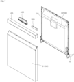
- FIG. 3 is a front perspective view of the door 3 according to one embodiment.
- FIG. 4 is a rear perspective view of the door 3 of FIG. 3 .
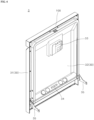
- the door 3 opens and closes the tub 2 having the washing space 21 defined therein, and may include a door body 30, a manipulation unit 100, and a hinge 35.
- the door body 30 may occupy a significant area of the door 3 and may open and close a front open surface of the tub 2.
- the hinge 35 may be mounted on a bottom of the door body 30 and may be composed a pair of hinges respectively disposed at both opposing sides of the door body 30.
- the hinge 35 may be pivotably mounted on the bottom of the tub 2, and the door 3 may pivot with respect to the tub 2 around the hinge 35, so that the door 3 may close or open the tub 2.
- the door body 30 may be formed by combining an outer panel 31 and a liner 32 with each other.
- the outer panel 31 may constitute an outer portion of the door 3, and the manipulation unit 100, which will be described later, may be mounted on an upper end of the outer panel 31.
- the liner 32 may be disposed between the outer panel 31 and the tub 2 and may be combined with the outer panel 31.
- the liner 32 may act as a seal between the door body 30 of the door 3 and the tub 2 to prevent the washing water in the washing space of the tub 2 from leaking out of the washing space of the dishwasher when the door 3 has pivoted to close the open surface of the tub 2.
- the liner 32 may be mounted on an inner surface of the door 3 to act as the seal between the tub 2 and the door 3.
- a receiving device 33 receiving and storing therein detergents, etc. may be disposed on an inner surface of the liner 32.
- the detergent contained in the receiving device 33 may be input into the washing space of the tub 2 in an amount required to washing the dish during the washing process and may be mixed with the washing water in the washing space.
- the hinges 35 may be installed on both opposing outer sides of a lower end portion of the liner 32, respectively.
- a steam injection unit 34 may be disposed on the lower end of the liner 32 and may inject the steam into the washing space of the tub 2 during the operation of the dishwasher.
- the steam injection unit 34 may be mounted on an inner surface of the lower end of the liner 32 which faces the washing space 21, so that a nozzle thereof faces the washing space 21 in the tub 2. Furthermore, the manipulation unit 100 may be mounted on an upper end of the liner 32.
- the manipulation unit 100 may be disposed on the door 3 and may receive a manipulation command from the user.
- the manipulation unit 100 may have an elongate rectangular bar shape.
- the manipulation unit may be mounted on the upper end of the door body 30.
- the manipulation unit 100 may be mounted on the upper end of the door body 30.
- the manipulation unit 100 may be coupled to the upper end of each of the outer panel 31 and the liner 32 which constitute the door body 30. Accordingly, when the outer panel 31 and the liner 32 are coupled to each other, the manipulation unit 100 may be located on the upper end of a combination of the outer panel 31 and the liner 32.
- the manipulation unit 100 may serve as a handle which the user may hold when opening and closing the door 3.
- the upper end of the outer panel 31 may have an inclined surface and the manipulation unit 100 may be coupled to an upper end of the inclined surface.
- a recess may extend in a lateral direction of the door 3 and may be defined between an upper end of a non-inclined front surface of the outer panel 31 and the manipulation unit 100.
- the user may hold the bottom of the manipulation unit 100 through the recess and may rotate the door 3 of the dishwasher around the hinge 3 to open or close the front open surface of the tub.
- a handle 500 with an open bottom which will be described later may be mounted on the manipulation unit 100.
- the manipulation unit 100 may receive a manipulation command.
- the manipulation unit 100 may operate in a touch recognition scheme. Accordingly, the manipulation unit 100 may be provided with an input unit configured to receives a user's manipulation command.
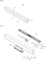
- FIG. 5 is a perspective view showing the manipulation unit 100 according to one embodiment.
- FIG. 6 is an exploded perspective view showing the manipulation unit 100 according to one embodiment.
- the manipulation unit 100 may have the elongate rectangular bar shape, may have an inner space defined therein for accommodating therein parts, and may have an open one surface. The open surface may be closed with the liner 32 when the manipulation unit 100 is mounted on the door 3.
- the manipulation unit 100 may be formed by combining panels with each other such that the space for accommodating therein components is defined by the panels. These panels may include a front panel 110, a lower panel 120, an upper panel 130, and a side panel 140. In this regard, a rear surface of the manipulation unit 100 may be open.
- the front panel 110 may constitute a front surface of the manipulation unit 100, and a casing 240 may be disposed on an inner side surface of the front panel.
- the lower panel 120 may be bent from the front panel 110 and may constitute a lower surface of the manipulation unit 100.
- the front panel 110 may constitute the front portion of the manipulation unit 100, the lower panel 120 may constitute a bottom of the manipulation unit 100, and the upper panel 130 may constitute a top of the manipulation unit 100, and the side panel 140 may block each of both opposing sides of the manipulation unit 100.
- the front panel 110, the lower panel 120, the upper panel 130, and the side panels 140 may be combined with each other to form an outer appearance of the manipulation unit 100.
- the space in which the components are accommodated may be defined by the front panel 110, the lower panel 120, the upper panel 130, and the side panels 140.
- the manipulation unit 100 may operate, for example, in a capacitive touch input scheme. Accordingly, the user may input a command signal to the dishwasher by touching the manipulation unit 100.
- Each of the panels of the manipulation unit 100 may be semi-transmissive. Thus, each of the panels of the manipulation unit 100 ensures that the parts contained in the inner space are not visible to a viewer from a design perspective. Light emitted from the light-emitting unit 210 may pass through each panel and may be perceived by the user.
- each of the panels forming the outer appearance of the manipulation unit 100 may be made of, for example, ABS material which may be semi-transmissive so that the light passes through the ABA material while the components contained in the inner space defined by the panels made of the ABA material are not visible to the user.
- the manipulation unit 100 may include a first input unit 200, a second input unit 410, a timer 420, and the handle 500.
- the first input unit 200 may be included in the manipulation unit 100 and may receive a user's manipulation command.
- the first input unit 200 may be oriented so as to face in a frontward direction of the dishwasher. Accordingly, the first input unit 200 may be positioned in the inner space defined by the panels of the manipulation unit 100 such that a front surface of the first input unit 200 faces the front panel 110.
- the second input unit 410 may receive a user's manipulation command and may be oriented so as to face upwardly of the dishwasher. Accordingly, the second input unit 410200 may be positioned in the inner space defined by the panels of the manipulation unit 100 such that an upper surface thereof faces the upper panel 130.
- the second input unit 410 may receive general command signals related to the operation of the dishwasher. Therefore, the second input unit 410 may include devices for receiving power on/off, setting of a washing time, a command for input or discharge of the washing water, and other various command, a marker for providing information related to input of a manipulation command to the user, and a lighting device that indicates an operation status of the dishwasher.
- the second input unit 410 is oriented so as to face upwardly while being disposed on the upper end of the door 3, the user opens the door 3 and conveniently touches the upper panel 130 facing the second input unit 410 to control the operation of the dishwasher.
- the timer 420 may provide the user with, for example, a time remaining until the washing is completed. Accordingly, the timer 420 may be provided with a time display 421 that displays the time remaining until the washing is completed.
- the timer 420 may be positioned in the inner space defined by the panels of the manipulation unit 100 such that a front surface thereof having the time display 421 faces the front panel 110.
- the second input unit 410 oriented so as to face upwardly of the door 3 cannot be visible to the user. This is because when the door 3 is closed, the second input unit 410 is screened with a top of the housing of the dishwasher or an indoor structure.
- the time display 421 of the timer 420 may be oriented such that a display face thereof faces the front surface of the door 3.
- the user may recognize time information while the dishwasher is operating.
- time display 421 of the timer 420 may be oriented such that the display face thereof faces the front surface of the door 3, the user may visually recognize the time information provided from the timer 420 even when the door 3 is closed.
- the handle 500 may have at least a portion mounted in the manipulation unit 100 and have an open lower surface.
- the recess may extend in the lateral direction of the door 3 and may be defined between the upper end of the non-inclined front surface of the outer panel 31 and the manipulation unit 100.
- the recess may communicate with the open lower surface of the handle 500. Accordingly, the user may conveniently open or close the door 3 by inserting his or her hand into the handle 500 through the recess and the open bottom of the handle.
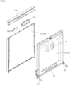
- FIG. 7 is a front exploded perspective view of the door 3 according to one embodiment.
- FIG. 8 is a rear exploded perspective view of the door of FIG. 7 .
- FIG. 9 is a perspective view showing the first input unit 200 according to one embodiment.
- FIG. 10 is an exploded perspective view of FIG. 9 .
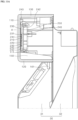
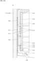
- FIG. 11A is an enlarged cross-sectional view of a portion of the door 3 according to one embodiment.
- FIG. 11B is an enlarged cross-sectional view of a portion A in FIG. 11A .
- the first input unit 200 may include a light-emitting unit 210, a sensing unit 220, and a conductive member 230.
- the light-emitting unit 210 may emit light in a frontward direction of the door 3 to guide the user to a touch position. Since the light emitted from the light-emitting unit 210 passes through the front panel 110 made of the semi-transmissive material, the user may see the position of the light with his or her eyes and know the touch position.
- the light-emitting unit 210 may be embodied as, for example, an LED (light emitting diode).
- the light-emitting unit 210 may have a structure in which a plurality of LEDs are arranged to be spaced apart from each other.
- the front surface of the first input unit 200 faces the rear surface of the front panel 110 constituting the front portion of the manipulation unit 100.
- the front surface of the first input unit 200 faces in the frontward direction of the door 3.
- the light-emitting unit 210 may radiate light in the frontward direction of the dishwasher. Therefore, in a state in which the door 3 is closed, the light from the light-emitting unit 210 may be emitted to an outside out of the dishwasher without being disturbed by a structure disposed on top of the dishwasher or the parts constituting the top of the dishwasher itself.
- the sensing unit 220 may be disposed at a position spaced apart from a position of the light-emitting unit 210 and may sense a command signal from the user.
- the user's command signal may be sensed by the sensing unit 220 in, for example, a capacitive touch recognition scheme. That is, the sensing unit 220 may detect change in current when the user's hand touches the front panel 110 and sense the user's command signal based on the detected change.
- Each of the light-emitting unit 210 and the sensing unit 220 may occupy a certain volume. Therefore, it is difficult for the light-emitting unit 210 and the sensing unit 220 to be located at the same position in the first input unit 200. For this reason, in an embodiment, the light-emitting unit 210 and the sensing unit 220 may be respectively disposed at positions spaced apart from each other in the first input unit 200.
- the sensing unit 220 In order for the sensing unit 220 to detect the user's command signal, the user needs to accurately touch a position of the front panel 110a overlapping, in a front-rear direction, a position where the sensing unit 220 is disposed.
- the user may recognize the touch position of the light-emitting unit 210 based on the light from the light-emitting unit 210.
- a command signal should be input to the sensing unit 220 located at the position spaced from the light-emitting unit 210.
- the sensing unit 220 should be electrically connected to the light-emitting unit 210.
- the first input unit 200 may be provided with the conductive member 230 that electrically connects the light-emitting unit 210 and the sensing unit 220 to each other.
- the conductive member 230 may be made of a conductive material and may have a form of a thin film. Since the light-emitting unit 210 and the sensing unit 220 are electrically connected to each other via the conductive member 230, the sensing unit 220 spaced from the light-emitting unit 210 may receive the user's command signal when the user touches the light-emitting unit 210.
- the user's command signal may be input to the light-emitting unit 210 of the first input unit 200 of the manipulation unit 100, and the input command signal may be transmitted to the sensing unit 220 through the conductive member 230.
- the light-emitting unit 210 having a certain volume and the sensing unit 220 having a certain volume may be spaced apart from each other and may be electrically connected to each other via the conductive member 230.
- the user may recognize the light-emitting unit 210 based on the light therefrom, and touch the position where the light-emitting unit 210 is located, so that the command signal may be input to the sensing unit 220 via the conductive member 230.
- the user may conveniently pause or cancel the pause and restart the dishwasher by touching the position of the light-emitting unit 210.
- the surface of the manipulation unit 100 may simple and neat, thereby enhancing the aesthetics of the design.
- the conductive member 230 may be disposed in front of the sensing unit 220 and may contact a front surface of the sensing unit 220, and may be disposed in front of the light-emitting unit 210, and may pass the light emitted from the light-emitting unit 210 therethrough.
- a light diffusion sheet 231 may be disposed on a position of the conductive member 230 overlapping, in the front-rear direction, the light-emitting unit 210.
- the command signal may be transmitted to the sensing unit 220 through the conductive member 230.
- the first input unit 200 may be disposed in the inner space of the manipulation unit 100 so that the light-emitting unit 210 faces in the frontward direction of the door 3 when the door 3 is closed.
- the first input unit 200 may be mounted in the manipulation unit 100 so that the front surface thereof faces the rear surface of the front panel 110 of the manipulation unit 100.
- the light emitted from the light-emitting unit 210 is directed the frontward direction of the door 3.
- the light emitted from the light-emitting unit 210 travels in the frontward direction of the door 3 without interference with other parts of the dishwasher or indoor structures, so that the user may touch the light-emitting unit 210 without opening the door 3.
- the user recognizes the position of the light-emitting unit 210 with his eyes without opening the door 3 and touches the light-emitting unit 210 to stop the operation of the dishwasher.
- the first input unit 200 is disposed in the manipulation unit 100 so as to face in the frontward direction of the door 3.
- the user may recognize the position of the first input unit 200 and touch the first input unit 200 without interference from other parts of the dishwasher or indoor structures to conveniently stop the operation of the dishwasher.
- the conductive member 230 may be formed to surround the light-emitting unit 210 and cover the sensing unit 220.
- the conductive member 230 may be constructed such that an area thereof corresponding to the light-emitting unit 210 is larger than an area of the light-emitting unit 210. Therefore, due to the conductive member 230, an effective touch area to the user may be larger than the area of the light-emitting unit 210, so that the user may touch the light-emitting unit 210 or a position adjacent to the light-emitting unit 210 in a relatively large area to input the command signal.
- the conductive member 230 may be constructed such that an area thereof corresponding to the sensing unit 220 may be larger than the area of the sensing unit 220. Therefore, the contact area between the conductive member 230 and the sensing unit 220 may be maximized. Thus, a possibility at which the command fails to be sent from the conductive member 230 to the sensing unit 220 due to poor contact between the conductive a portion and the sensing unit 220 may be significantly reduced.
- the sensing unit 220 may be made of a material with high elastic deformation. Therefore, the sensing unit 220 may be manufactured to have a relatively large volume and may be disposed in the manipulation unit 100. The sensing unit 220 may elastically deform so as to adhere to the conductive member 230. Accordingly, occurrence of contact failure between the conductive member and the sensing unit 220 may be suppressed.
- the first input unit 200 may include a casing 240 and a circuit board 250.
- the casing 240 may be coupled to the manipulation unit 100, and may accommodate therein the light-emitting unit 210 and the sensing unit 220.
- the conductive member 230 may be disposed on an outer side surface of the casing 240. When the casing 240 is mounted in the inner space of the manipulation unit 100, the conductive member 230 may be disposed between the front panel 110 and the casing 240.
- one side surface of the conductive member 230 may be in contact with the inner side surface of the front panel 110, while the other side surface thereof may be in contact with the sensing unit 220. Accordingly, when the user touches the position of the front panel 110 corresponding to the light-emitting unit 210, the command signal may be transmitted to the sensing unit 220 through the front panel 110 and the conductive member 230.
- the circuit board 250 may be accommodated in the casing 240.
- the light-emitting unit 210 and the sensing unit 220 may be mounted on the circuit board.
- the circuit board 250 may be connected to a control unit provided in the dishwasher and may transmit the command signal input from the user to the control unit.
- a first through-hole 244 and a second through-hole 245 may be defined in the casing 240.
- the first through-hole 244 may be formed at a position corresponding to a position where the light-emitting unit 210 is disposed, and may be provided to allow light emitted from the light-emitting unit 210 to pass therethrough.
- the second through-hole 245 may be formed at a position corresponding to a position where the sensing unit 220 is disposed, and the sensing unit 220 may be inserted into the second through-hole.
- the first through-hole 244 and the second through-hole 245 may be covered with the conductive member 230 disposed on the front surface of the casing 240.
- the light emitted from the light-emitting unit 210 may pass through the casing 240 through the first through-hole 244 and be directed in a frontward direction of the manipulation unit 100.
- the sensing unit 220 may extend through the casing 240 through the second through-hole 245, and the front surface of the sensing unit 220 may be in contact with the conductive member 230.
- the conductive member 230 may include the light diffusion sheet 231.
- the light diffusion sheet 231 may be disposed at a position corresponding to a position where the light-emitting unit 210 is disposed and may be made of a transmissive or semi-transmissive material so that the light emitted from the light-emitting unit 210 may pass therethrough.
- the light diffusion sheet 231 may allow the light emitted from the light-emitting unit 210 to be spread uniformly. Accordingly, the light having passed through the light diffusion sheet 231 may have a uniform pattern and uniform illuminance throughout the optical diffusion sheet.
- the light diffusion sheet 231 may be made of a conductive material. Therefore, when the user touches a position of the front panel corresponding to the position of the light-emitting unit 210, a command signal may be input to the light diffusion sheet 231 and then may be transmitted from there light diffusion sheet to the sensing unit 220.
- the light diffusion sheet 231 is transmissive or semi-transmissive and is made of the conductive material
- the light diffusion sheet 231 may be made of, for example, indium thin oxide (ITO).
- the liner 32 of the door 3 may extend upwardly beyond the upper end of the outer panel 31. Due to this structure, a space where the manipulation unit 100 may be mounted may be formed on top of the upper end of the outer panel 31 and on a front surface of the upper end of the liner 32.
- the manipulation unit 100 may be disposed in the space defined on top of the upper end of the outer panel 31 and on a front surface of the upper end of the liner 32 and may be coupled to each of the outer panel 31 and the liner 32. Due to this structure, the user may conveniently access the manipulation unit 100 and may easily touch the manipulation unit 100 to control the operation of the dishwasher.
- a rear portion of the manipulation unit 100 may be coupled to the front surface of the upper end of the liner 32.
- the manipulation unit 100 may be firmly coupled to the liner 32 via a coupling member such as a bolt, and may be detachably coupled to each other.
- an inserted protrusion 161 may protrude downwardly from a bottom of the lower panel of the manipulation unit 100, and the inserted protrusion 161 may be inserted into a hole formed in the upper end of the outer panel 31.
- the manipulation unit 100 may be fastened to the upper end of the outer panel 31 via the inserted protrusion 161.
- the manipulation unit 100 In mounting the manipulation unit 100 on the door 3, first, the manipulation unit 100 may be installed on top of the outer panel 31 while the inserted protrusion 161 is inserted into the hole formed in the upper end of the outer panel 31, and then, the manipulation unit 100 and the liner 32 may be coupled to each other using a coupling member. Accordingly, the manipulation unit 100 may be stably and firmly mounted on a top of the door 3.
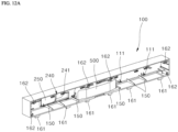
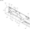
- FIG. 12A is a perspective view showing the manipulation unit 100 and parts mounted in the manipulation unit 100 according to an embodiment.
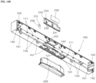
- FIG. 12B is a view of FIG. 12A in a different view direction from a view direction of FIG. 12A .
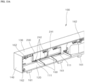
- FIG. 13A is an enlarged view of a portion of FIG. 12A .
- FIG. 13B is an enlarged view of a portion of FIG. 12B .
- FIG. 14A is an exploded perspective view of FIG. 12A .
- FIG. 14B is an exploded perspective view of FIG. 12B .
- FIG. 15 is a perspective view of FIG. 14A in a different view direction from a view direction of FIG. 14A .
- the casing 240 may be provided with a mounting guide 241 and a first support protrusion 242.
- the mounting guide 241 may protrude from the inner side surface of the casing 240 so as to extend across a board receiving space of the casing 240, and may guide a mounting position of the circuit board 250.
- a portion of the circuit board 250 may be fitted with the mounting guide 241 such that the circuit board 250 may be stably received in the board receiving space of the casing 240.
- the circuit board 250 may be received in the receiving space of the casing 240. Therefore, this receiving space may be formed to have a space corresponding to the shape of the circuit board 250.
- the mounting guide 241 may have an inclined portion, and the circuit board 250 may have an inclinedly extending groove at a position corresponding to a position of the inclined surface of the mounting guide 241. Due to this structure, an alignment between the circuit board 250 and the mounting guide 241 when the circuit board 250 is fitted with the mounting guide 241 may be easily achieved based on the inclined portions. Accordingly, the worker assembling the first input unit 200 may conveniently mount the circuit board 250 into the casing 240 while achieving the alignment between the circuit board 250 and the mounting guide 241 based on the inclined portion of the mounting guide 241.
- the first support protrusion 242 may protrude from the inner surface of the casing 240 inwardly of the casing 240 and may support the circuit board 250.
- the first support protrusion 242 may be provided in aa shape of a hook.
- the circuit board 250 may be fitted into the board receiving space of the casing 240 while being engaged with the first support protrusion 242.
- the first support protrusion 242 may prevent the circuit board 250 from being removed from the casing 240 so that the circuit board 250 may be maintained in the firmly fitted into the board receiving space of the casing 240.
- the first support protrusion 242 may be formed at each of lower and upper ends of the casing 240, and may protrude inwardly of the casing 240.
- the first support protrusion 242 formed at the upper end of the casing 240 may be provided to be elastically deformable.
- the first support protrusion 242 formed at the upper end of the casing elastically deforms, and thus the circuit board 250 may be fitted into the board receiving space.
- the first support protrusion 242 at the upper end may be restored to its original shape.
- the upper and lower first support protrusions 242 may elastically press and support the rear surface of the circuit board 250. Accordingly, the circuit board 250 may be stably supported by the upper and lower first support protrusions 242.
- a gap may occur between an outer edge of the circuit board 250 and the casing 240. Through this gap, moisture from the tub 2 may flow into the sensing unit 220.
- the moisture flowing into the sensing unit 220 may deteriorate the performance of the sensing unit 220 or cause malfunction or failure thereof. Therefore, it is necessary to prevent the inflow of the moisture into the sensing unit 220.
- the gap between the edge of the circuit board 250 and the casing 240 may be sealed to prevent the moisture from flowing into the sensing unit 220 through the gap.
- This sealing structure may be implemented, for example, by placing a sealing member made of silicon on the edge of the circuit board 250.
- silicon may be applied into the gap between the edge of the circuit board 250 and the casing 240 to form a sealing structure.
- the manipulation unit 100 may include an inserted protrusion 161 and a fastening hole 162.
- the inserted protrusion 161 may protrude from the lower panel 120 of the manipulation unit 100 and may be provided in a plural manner.
- the inserted protrusions 161 may be arranged to be spaced apart from each other in a longitudinal direction of the manipulation unit 100.
- the inserted protrusion 161 may be inserted into a hole formed in the upper end of the outer panel 31, and thus the manipulation unit 100 may be coupled to the outer panel 31.
- the fastening hole 162 may be formed in the rear surface of the rear panel of the manipulation unit 100 and may face toward the liner 32, and may be provided in a plural manner.
- the fastening holes 162 may be arranged to be spaced apart from each other in the longitudinal direction of the manipulation unit 100.
- a coupling member such as a bolt may be fastened into the fastening hole 162.
- the coupling member may be inserted into and pass through each of the hole formed at the front surface of the upper end of the liner 32 and the fastening hole 162, and thus may couple the manipulation unit 100 to the liner 32.
- the inserted protrusion 161 may be inserted into the hole formed in the upper end of the outer panel 31, and thus the manipulation unit 100 may be coupled to the outer panel 31.
- the coupling member may be inserted into and pass through each of the hole formed at the front surface of the upper end of the liner 32 and the fastening hole 162, and thus may couple the manipulation unit 100 to the liner 32. Due to this structure, the manipulation unit 100 may be stably mounted on the door 3.
- the front panel 110 of the manipulation unit 100 may constitute the front surface of the manipulation unit 100, and the casing 240 may be mounted on the rear surface of the front panel.
- the lower panel 120 of the manipulation unit 100 may be bent from the front panel 110 and constitute the lower surface of the manipulation unit 100.
- the front panel 110 may include a first support 111 that protrudes from the inner side surface thereof and supports the bottom of the casing 240.
- a plurality of first supports may be arranged in the longitudinal direction of the manipulation unit 100.
- the casing 240 may be maintained in the mounted state inside the manipulation unit 100 while being supported on the first supports 111.
- the first support 111 may be provided in a hook shape. Therefore, when the worker places the casing 240 at the mounting position of the manipulation unit 100 and presses the casing, the casing 240 may be mounted in the manipulation unit 100 so as to be held by the first supports 111. Thus, the first support 111 may prevent the casing 240 from being removed from the manipulation unit 100 so that the casing 240 may be maintained in the mounted state in the manipulation unit 100.
- the handle 500 may be accommodated in the inner space defined by the panels of the manipulation unit 100 and may have a lower surface having an open portion.
- a through-hole 121 may be formed in the lower panel 120 of the manipulation unit 100 at a position thereof overlapping a position where the open portion of the lower surface of the handle 500 is disposed.
- the handle 500 may be disposed in the inner space of the manipulation unit 100, the user may put his hand into the manipulation unit 100 through the through-hole 121 and the open portion of the lower surface of the handle 500, and grab the handle, and rotate the door 3 to open or close the open front surface of the tub.
- the handle 500 may be located at a center of the upper end of the door 3 and a center of the manipulation unit 100 for the user's convenience and to ensure that a uniform force is transmitted to each of the pair of hinges 35 to rotate the door 3 smoothly to open or close the washing space.
- the through-hole 121 may also be disposed in the central of the manipulation unit 100.
- the casing 240 and the handle 500 may be disposed at the same position. Thus, due to the respective volumes of the casing 240 and the handle 500, a total volume of the door 3 may increase.
- the user may put his/her hand through the open portion of the handle 500 and grasp the handle such that the thumb come into unintentional contact with the first input unit 200 positioned at the same position as the handle or at a position adjacent thereto. Such contact may cause the dishwasher to unintentionally stop the operation or resume the operation from a stopped state.
- the casing 240 may be positioned to be spaced apart from the handle 500 by a predetermined distance in the lateral direction of the dishwasher. Accordingly, the casing 240 may be disposed adjacent to one of both opposing ends in the lateral direction of the manipulation unit 100 so as to be spaced away from the center of the manipulation unit 100.
- a distance in the dishwasher's lateral direction between the casing 240 and the handle 500 should be large so as to prevent the user's thumb from unintentionally contacting the first input unit 200 when the user holds the handle 500.
- the first input unit 200 may be disposed on a left side of the handle 500 in a rear view of the manipulation unit 100. In another embodiment, the first input unit 200 may be disposed on a right side of the handle 500 in the rear view of the manipulation unit 100. Even in this case, a distance in the dishwasher's lateral direction between the casing 240 and the handle 500 should be large so as to prevent the user's thumb from unintentionally contacting the first input unit 200 when the user holds the handle 500.
- the manipulation unit 100 Since other parts may be mounted in the inner space of the manipulation unit 100, it may be useful for the manipulation unit 100 to be provided with a plurality of positions at which the first input unit 200 is mounted. Accordingly, in the manipulation unit 100, the first input unit 200 may be mounted on either the left or right side of the handle 500, thereby diversifying the position of the first input unit 200 in the manipulation unit 100 to increase space use efficiency in the manipulation unit 100.
- the first support 111 for supporting the first input unit 200 may be disposed on the right side of the handle 500, and this first support 111 may be provided in a plural manner.
- the plurality of first supports 111 may be arranged so as to be spaced form each other by a predetermined distance in the longitudinal direction of the manipulation unit 100 along an entirety of the manipulation unit 100 except for a position where the handle 500 is disposed.
- the casing 240 may include a second support protrusion 243.
- the second support protrusion 243 may protrude upwardly from the outer side surface of the casing 240 and may support the casing 240 while contacting the inner side surface of the manipulation unit 100.
- the second support protrusion 243 may be provided in a plural manner.
- the second support protrusions 243 protruding upwardly of the casing 240 may be in contact with the front panel of the manipulation unit 100 so as to support the casing 240.
- the first supports 111 protruding from the front panel of the manipulation unit 100 may be in contact with the bottom of the casing 240 to support the casing 240.
- the casing 240 may be stably supported by the second supports 243 and the first supports 111 and thus may be maintained in the mounted state in the manipulation unit 100.
- the manipulation unit 100 may further include a reinforcing rib 150.
- the reinforcing rib 150 may protrude upwardly from an inner upper surface of the lower panel 120 and an end of the rib 150 may be coupled to the inner side surface of the front panel 110.
- a plurality of reinforcing ribs 150 may be provided, and the reinforcing ribs 150 may be arranged so as to be spaced from each other by a predetermined spacing in the longitudinal direction of the manipulation unit 100, that is, in the lateral direction of the door 3.
- the lower panel 120 may support loads of a plurality of components accommodated in the manipulation unit 100, including the first input unit 200. Additionally, the lower panel 120 needs to be stably coupled to the outer panel 31. For this reason, the lower panel 120 should not be deformed under an external force.
Landscapes
- Washing And Drying Of Tableware (AREA)
Abstract
Description
- The present disclosure relates to a dishwasher. More specifically, the present disclosure relates to a dishwasher having an input unit configured to may temporarily stop an operation of the dishwasher and is disposed at a position at which a user may conveniently touch the input unit even during an operation of the dishwasher.
- A dishwasher is a device that washes dishes by spraying washing water on the dish as a washing target stored therein. In this regard, detergents may be contained in the washing water used for washing.
- Generally, the dishwasher includes a washing tub that defines a washing space, a dish rack that accommodates therein the washing target while being disposed in the washing tub, a spraying arm that sprays washing water into the dish rack, and a sump that stores therein the washing water and supplies the washing water to the spraying arm.
- By using the dishwasher, a time and effort required to wash the dishes as the washing target after a meal may be reduced, thus contributing to user convenience.
- The dishwasher may be equipped with a manipulation unit through which the user may input a command for operation of the dishwasher. The user may generally input a command signal to the dishwasher by touching a button disposed on the manipulation unit.
- Prior art related to the manipulation unit is disclosed in
Korean Patent Application Publication No. 10-2017-0082406 - As disclosed in the prior art, a manipulation button for manipulating the dishwasher is disposed on an upper surface of the door as the most convenient position for the user to access the manipulation button.
- The dishwasher is generally positioned indoors in a built-in scheme. Therefore, when the manipulation button is located on the upper surface of the door that opens and closes the washing space of the dishwasher, it may be most convenient for the user to touch the manipulation button. For this reason, the manipulation button is generally disposed on the upper surface of the door.
- When the door is closed, the upper surface of the door may be screened by an interior structure, or an upper end structure of the dishwasher such that the manipulation button may not be accessed by the user.
- When the user intends to temporarily stops the operation of the dishwasher while the dishwasher is in operation, the user cannot touch a pause button located on the upper surface of the door due to the position of the manipulation button.
- A structure is generally adopted in which the operation of the dishwasher is stopped for the user's safety when the user opens the door while the dishwasher is in operation. Therefore, while the dishwasher is in operation, the user may stop the operation of the dishwasher by opening the door.
- In this regard, the operation of the dishwasher is stopped as soon as the door is opened. That is, a washing water spray device and a heated steam spray device disposed inside the dishwasher are still operating when the door is opened. Thus, when the user opens the door, there is a risk that the washing water, the heated steam and substance floating inside the dishwasher may splash onto the user.
- Therefore, for the user's convenience and safety, it is necessary to provide a separate input unit to temporarily stop the dishwasher in an operating state. Furthermore, this input unit needs to be disposed in a position at which the user may easily access the input unit even during the operation of the dishwasher rather than on the upper end of the door as a position at which the user cannot touch the input unit during the operation of the dishwasher.
- Additionally, for the user's convenience, the position of the input unit for inputting a pause command needs to be displayed so as to be visually identified. To this end, a display device may be implemented using a light-emitting unit so that the user may recognize the position of the input unit with the naked eye even under a dark environment.
- In this regard, a sensing unit configured to recognizes the user's touch is provided separately from the light-emitting unit. Therefore, the user recognizes a user input position through the light-emitting unit, and touches the sensing unit which is separate from the light-emitting unit to input a command signal to stop the dishwasher.
- The light-emitting unit requires a space in which a light-emitting device such as a LED is installed. Therefore, the light-emitting unit and the sensing unit configured to detects the user's touch cannot be disposed at the same position.
- The user intends to input the command signal to pause the dishwasher by touching the sensing unit configured to indicates a user input position. However, the light-emitting unit and the sensing unit are not located at the same position. Thus, the user may touch the light-emitting unit. In this case, the command signal may not be input to the dishwasher.
- To solve this problem, a separate mark indicating a position of the sensing unit may be disposed at the position of the sensing unit. However, it may be difficult for the user to identify the mark under the dark surrounding.
- Furthermore, when the light-emitting unit for indicating the user input position and the mark indicating the position of the sensing unit configured to should actually be touched by the user are spaced from each other, this may cause confusion for the user as to where to touch. Furthermore, the mark may deteriorate the aesthetics of the dishwasher's design. A solution to these problems is required.
- A purpose of the present disclosure is to provide a dishwasher with an input unit configured to may temporarily stop the operation of the dishwasher and may be disposed in a position at which the user may conveniently touch the input unit even during the operation of the dishwasher.
- In addition, a purpose of the present disclosure is to provide a dishwasher having a structure that allows the user to touch the light-emitting unit even when the light-emitting unit configured to displays the user touch position and the sensing unit configured to detects the user's touch are spaced from each other to stop the operation of the dishwasher.
- Additionally, a purpose of the present disclosure is to provide a dishwasher with a structure that enhances design aesthetics of the dishwasher by omitting a separate mark indicating the position of the sensing unit configured to detects the user's touch.
- Purposes according to the present disclosure are not limited to the above-mentioned purpose. Other purposes and advantages according to the present disclosure that are not mentioned may be understood based on following descriptions, and may be more clearly understood based on embodiments according to the present disclosure. Further, it will be easily understood that the purposes and advantages according to the present disclosure may be realized using means shown in the claims and combinations thereof.
- A manipulation unit configured to receives a user's command signal may be installed at the upper end of the door of the dishwasher according to an embodiment. The manipulation unit may include a first input unit, a second input unit, a timer, and a handle.
- The first input unit may be provided in the manipulation unit and may receive a user's manipulation command. The first input unit may be mounted so as to face in a frontward direction of the dishwasher. Accordingly, the first input unit may be disposed in the manipulation unit such that a front surface of the first input unit to face a front panel.
- The second input unit may receive the user's operation command and may be mounted to face upwardly of the dishwasher. Accordingly, the second input unit may be disposed in the manipulation unit such that an upper surface of the second input unit may face an upper panel.
- A timer may provide the user with a time remaining until washing is completed, for example. Therefore, the timer may be equipped with a time display that displays the time remaining until the washing is completed. The timer may be disposed inside the manipulation unit so that a front surface of the time display faces the front panel.
- The handle may have at least a portion mounted in the manipulation unit and have an open portion of a lower surface thereof. A recess extending in a lateral direction of the door may be defined between an upper end of the outer panel and the manipulation unit. The open portion of the lower surface of the handle may communicate with the recess. Accordingly, the user may conveniently open or close the door by placing his/her hand into the handle through the recess and the open portion of the lower surface of the handle.
- The first input unit may receive a command to temporarily stop the dishwasher. When the user touches a portion of the front panel of the manipulation unit corresponding to the position of the first input unit once, the first input unit may recognize the touch and the dishwasher stops the operation. When the user touches the portion of the front panel of the manipulation unit corresponding to the position of the first input unit, the first input unit recognizes the touch and the dishwasher operates again.
- The first input unit may include a light-emitting unit, a sensing unit, and a conductive member. The light-emitting unit may emit the light to guide the user to the touch position. Since the light emitted from the light-emitting unit passes through the front panel made of a semi-transmissive material, the user may see the position of the light with his or her eyes and know the touch position.
- The sensing unit may be spaced away from the light-emitting unit and may detect the command signal from the user. The user's command signal may be sensed by the sensing unit, for example, in a capacitive touch recognition scheme. In other words, the sensing unit may detect change in current when the user's hand touches the front panel and sense the user's command signal based on the detected change.
- The conductive member may be electrically connected to the sensing unit and may transmit the user's command signal to the sensing unit. For example, at least a portion of the conductive member may be made of a carbon material. However, the present disclosure is not limited thereto, and the conductive member may be manufactured using other conductive materials.
- Disclosed is a dishwasher having a door that opens and closes a washing space. The door may include a manipulation unit configured to receive a manipulation command from a user; and a first input unit disposed in the manipulation unit, wherein the first input unit may include a light-emitting unit configured to radiate light in a frontward direction of the door to guide the user to a touch position; a sensing unit disposed at a position spaced apart from a potion of the light-emitting unit and configured to detect a command signal from the user; and a conductive member electrically connected to the sensing unit so as to transmit the command signal of the user to the sensing unit.
- The conductive member may be disposed in front of the sensing unit and contacts a front surface of the sensing unit, wherein the conductive member may be disposed in front of the light-emitting unit, and passes light emitted from the light-emitting unit therethrough.
- The command signal of the user may be input to the light-emitting unit of the first input unit, and wherein the input command signal may be transmitted to from the light-emitting unit to the sensing unit through the conductive member.
- The first input unit may be disposed in the manipulation unit so that the light-emitting unit faces in a frontward direction of the door in a state in which the door closes the washing space.
- In a front view of the door, the conductive member may be formed to surround the light-emitting unit and cover the sensing unit.
- The first input unit may include a casing coupled to the manipulation unit, and constructed to accommodate therein the light-emitting unit and the sensing unit, wherein the conductive member may be disposed on an outer side surface of the casing; and a circuit board accommodated in the casing, wherein the light-emitting unit and the sensing unit may be mounted on the circuit board.
- The casing may have a first through-hole defined at a position of the casing corresponding to a position at which the light-emitting unit is disposed, wherein light emitted from the light-emitting unit passes through the first through-hole; and a second through-hole defined at a position of the casing corresponding to a position at which the sensing unit is disposed, wherein the sensing unit may be inserted into the second through-hole.
- The conductive member may include a light diffusion sheet disposed thereon at a position corresponding to a position at which the light-emitting unit may be disposed, wherein the light diffusion sheet may be made of a transmissive or semi-transmissive material through which the light emitted from the light-emitting unit passes.
- The casing may include a mounting guide protruding from an inner side surface of the casing to extend across a board receiving space of the casing, wherein the mounting guide guides a mounting position of the circuit board; and a first support protrusion protruding from an inner surface of the casing inwardly of the casing so as to support the circuit board.
- The casing may further include a second support protrusion protruding from a front outer surface of the casing and contacting an inner surface of the manipulation unit so as to support the casing.
- The manipulation unit may include a front panel constituting a front surface of the manipulation unit, wherein the casing may be disposed on an inner side surface of the front panel; and a lower panel bent from a lower end of the front panel and constituting a lower surface of the manipulation unit, wherein the front panel includes a first support protruding from the inner side surface thereof so as to support the bottom of the casing.
- The conductive member may be disposed between the front panel and the casing, wherein one side surface of the conductive member contacts the inner side surface of the front panel, and the other side surface of the model contacts the sensing unit.
- The manipulation unit may further include a handle having at least a portion received in the manipulation unit, wherein a portion of a lower surface of the handle may be open, wherein a through-hole may be defined in the lower panel of the manipulation unit at a position corresponding to a position where the open portion of the handle may be positioned.
- The casing may be positioned to be spaced apart from the handle by a predetermined distance in a lateral direction of the dishwasher.
- The manipulation unit may further include a reinforcing rib protruding from an inner upper surface of the lower panel, wherein an end of the reinforcing rib may be coupled to the inner side surface of the front panel.
- In the dishwasher according to the present disclosure, the light-emitting unit having a certain volume and the sensing unit having a certain volume may be spaced apart from each other and may be electrically connected to each other via the conductive member. Thus, the user may recognize the light-emitting unit based on the light therefrom, and touch the position where the light-emitting unit is located, so that the command signal may be input to the sensing unit via the conductive member.
- Therefore, the user may conveniently pause or cancel the pause and restart the dishwasher by touching the position of the light-emitting unit.
- Furthermore, there is no need to separately form a marker at the position of the sensing unit to inform the user of a position of the sensing unit. Furthermore, a situation where the marker formed at the position of the sensing unit may cause confusion as to whether the user should touch the light-emitting unit or the marker may be removed.
- Furthermore, since the marking indicating the position of the sensing unit is omitted, the surface of the manipulation unit may simple and neat, thereby enhancing the aesthetics of the design.
- Additionally, in the dishwasher according to the present disclosure, the first input unit is disposed in the manipulation unit so as to face in the frontward direction of the door. Thus, without opening the door even during operation of the dishwasher, the user may recognize the position of the first input unit and touch the first input unit without interference from other parts of the dishwasher or indoor structures to conveniently stop the operation of the dishwasher.
- In addition to the above-mentioned effects, the specific effects of the present disclosure are described below along with the description of the specific details for carrying out the present disclosure.
-
-
FIG. 1 is a schematic cross-sectional view of a dishwasher according to one embodiment. -
FIG. 2 is a perspective view of a dishwasher according to one embodiment. -
FIG. 3 is a front perspective view of a door according to one embodiment. -
FIG. 4 is a rear perspective view of the door ofFIG. 3 . -
FIG. 5 is a perspective view showing a manipulation unit according to one embodiment. -
FIG. 6 is an exploded perspective view showing a manipulation unit according to one embodiment. -
FIG. 7 is a front exploded perspective view of a door according to one embodiment. -
FIG. 8 is a rear perspective view of the door ofFIG. 7 . -
FIG. 9 is a perspective view showing a first input unit according to one embodiment. -
FIG. 10 is an exploded perspective view ofFIG. 9 . -
FIG. 11A is an enlarged cross-sectional view of a portion of a door according to one embodiment. -
FIG. 11B is an enlarged cross-sectional view of a portion A inFIG. 11A . -
FIG. 12A is a front perspective view showing a manipulation unit and parts mounted in the manipulation unit according to an embodiment. -
FIG. 12B is a rear view showing the manipulation unit and the parts mounted in the manipulation unitFIG. 12A . -
FIG. 13A is an enlarged view of a portion ofFIG. 12A . -
FIG. 13B is an enlarged view of a portion ofFIG. 12B . -
FIG. 14A is an exploded perspective view ofFIG. 12A . -
FIG. 14B is an exploded perspective view ofFIG. 12B . -
FIG. 15 is a perspective view ofFIG. 14A in a different direction. - The above-mentioned purposes, features, and advantages will be described in detail later with reference to the attached drawings, so that those skilled in the art in the technical field to which the present disclosure belongs may easily practice the technical ideas of the present disclosure. In describing the present disclosure, when it is determined that a detailed description of the publicly known technology related to the present disclosure may unnecessarily obscure the gist of the present disclosure, the detailed description thereof will be omitted. Hereinafter, a preferred embodiment according to the present disclosure will be described in detail with reference to the attached drawings. In the drawings, identical reference numerals are used to indicate identical or similar components.
- Although first, second, etc. are used to describe various components, these components are not limited by these terms. These terms are merely used to distinguish one component from another component. Thus, unless specifically stated to the contrary, the first component may be the second component.
- As used herein, the singular constitutes "a" and "an" are intended to include the plural constitutes as well, unless the context clearly indicates otherwise.
- Further, the terms "comprise", "comprising", "include", and "including" as used herein should not be construed as necessarily including all of various components or steps as described herein, and may be construed as excluding some components or some steps thereof. It will be further understood that the terms "comprise", "comprising", "include", and "including" as used herein specify presence of a component or a step, but do not preclude the presence or addition of another component or step.
- Throughout the present disclosure, "A and/or B" means A, B, or A and B, unless otherwise specified, and "C to D" means C inclusive to D inclusive unless otherwise specified.
- Throughout the present disclosure, "vertical direction" refers to the vertical direction of the dishwasher when the dishwasher is installed for daily use. "Left and right direction" means the direction perpendicular to the vertical direction. The front-back direction means a direction perpendicular to both the vertical direction and the left-right direction. "Bilateral direction" or "lateral direction" has the same meaning as the left-right direction, and these terms may be used interchangeably with each other in the present disclosure.
-
FIG. 1 is a schematic cross-sectional view of a dishwasher according to one embodiment. - Referring to
FIG. 1 , the dishwasher may include a housing that defines an outer appearance, atub 2 disposed inside the housing and having awashing space 21 defined therein for accommodating therein a dish as a washing target, adoor 3 pivotably coupled to abase 8 to selectively open and close thewashing space 21, asump 4 disposed under thetub 2 to store therein washing water, a dish rack 5 disposed in the washing space of thetub 2 to store therein the washing targets, and sprayingarms - The
tub 2 has thewashing space 21 defined therein to accommodates the dish therein, and the dish rack 5 and the sprayingarms washing space 21. Thetub 2 has one open surface, and one open surface may be opened and closed by thedoor 3. - The
door 3 is pivotably connected to the housing to selectively open and close thewashing space 21. For example, a bottom of thedoor 3 may be hinged-coupled to the housing. - In this case, the
door 3 may pivot around the hinge to open and close thetub 2. When thedoor 3 is opened, the dish rack 5 may extend from the washing space of the dishwasher, and the dish rack 5 having extended from the washing space may be supported by thedoor 3. - The
sump 4 includes astorage 41 that stores therein the washing water, asump cover 42 that separates thestorage 41 from thetub 2, awater supply unit 43 that supplies washing water from an external source to thestorage 41, awater discharger 44 that discharges the washing water in thestorage 41 to the outside, and awater supply pump 45 and a flow path 46 for supplying the washing water in thestorage 41 to the sprayingarms - The
sump cover 42 may be disposed on a top of thesump 4, and may distinguish thetub 2 from thesump 4. Furthermore, thesump cover 42 may have a plurality of collection holes defined therein through which the washing water sprayed into thewashing space 21 through the sprayingarms - That is, the washing water sprayed from the spraying
arms washing space 21, and may be collected to thestorage 41 of thesump 4 through the holes of thesump cover 42. - The
water supply pump 45 may be disposed on a side or a bottom of thestorage 41 and may supply the washing water to the sprayingarms - One end of the
water supply pump 45 may be connected to thestorage 41 and the other end thereof may be connected to the supply flow path 46. Animpeller 451 and amotor 453 may be provided inside thewater supply pump 45. When power is supplied to themotor 453, theimpeller 451 rotates, such that the washing water from thestorage 41 may be supplied to the sprayingarms - The supply flow path 46 may selectively supply the washing water supplied from the
water supply pump 45 to the sprayingarms - The supply flow path 46 may include a first supply flow path 461 connected to the
lower spraying arm 6, a secondsupply flow path 463 connected to theupper spraying arm 7 and atop nozzle 9, and a supply flowpath switching valve 465 that selectively opens and closes thesupply flow paths 461 and 467. In this regard, the supply flowpath switching valve 465 may control thesupply flow paths 461 and 463 to be opened sequentially or to be opened simultaneously. - The
washing space 21 may receive therein at least one dish rack 5 for storing therein dishes.FIG. 1 shows a dishwasher equipped with twodish racks 2. However, the present disclosure is not limited thereto. - For example, the dishwasher may include only one dish rack or three or more dish racks. In this case, the number of spraying arms may vary depending on the number of dish racks.
- The dish rack 5 may include a
lower rack 51 and anupper rack 53 for storing dishes therein. Thelower rack 51 may be disposed in thewashing space 21, and the dish may be stored therein. Theupper rack 53 may be disposed on top of thelower rack 51 and may accommodate a dish therein. In one example, a top rack may be disposed in a space between a top of theupper rack 53 and thetop nozzle 9, and a dish may be stored therein. - The
lower rack 51 may be located on top of thesump 4, and theupper rack 53 may be located on top of thelower rack 51. Each of thelower rack 51, theupper rack 53, and the top rack may be configured to extend from the washing space through the open surface of thetub 2. - For this purpose, a rail-type support may be disposed on an inner side surface of the
tub 2, and wheels may be disposed at bottoms of theracks - The spraying arm may be provided in the inner space of the
tub 2 and may spray the washing water toward the dish in the dish rack 5. The spraying arm may include thelower spraying arm 6, theupper spraying arm 7, and thetop nozzle 9. - The
lower spraying arm 6 may be pivotably disposed under thelower rack 51 and may spray the washing water on the dish. - The
upper spraying arm 7 may be pivotably disposed between thelower rack 51 and theupper rack 53 and may spray the washing water on the dish. - The
lower spraying arm 6 may be pivotably mounted at thesump cover 42 and may spray the washing water toward the dish stored in thelower rack 51. Theupper spraying arm 7 may be located on top of thelower spraying arm 6 and may spray the washing water toward the dish stored in theupper rack 53. Thetop nozzle 9 is provided in a top of thewashing space 21 and may spray the washing water onto thelower rack 51 and theupper rack 53. - As described above, the first supply flow path 461 may supply the washing water to the
lower spraying arm 6, and the secondsupply flow path 463 may supply the washing water to theupper spraying arm 7 and thetop nozzle 9. Referring toFIG. 1 , the dishwasher may include thebase 8. Thebase 8 may be disposed under thetub 2, and thetub 2 may be mounted thereon. Thebase 8 may provide a space to accommodate thesump 4 therein, and may provide a space to accommodate therein various devices such as the pump, a dry wind supply device, and other devices provided in the dishwasher. - Therefore, the
base 8 may have an outer wall for supporting the entire dishwasher. The space for accommodating therein the various devices may be defined by the outer wall. -
FIG. 2 is a perspective view of a dishwasher according to one embodiment.FIG. 3 is a front perspective view of thedoor 3 according to one embodiment.FIG. 4 is a rear perspective view of thedoor 3 ofFIG. 3 . Thedoor 3 opens and closes thetub 2 having thewashing space 21 defined therein, and may include adoor body 30, amanipulation unit 100, and ahinge 35. - The
door body 30 may occupy a significant area of thedoor 3 and may open and close a front open surface of thetub 2. Thehinge 35 may be mounted on a bottom of thedoor body 30 and may be composed a pair of hinges respectively disposed at both opposing sides of thedoor body 30. - The
hinge 35 may be pivotably mounted on the bottom of thetub 2, and thedoor 3 may pivot with respect to thetub 2 around thehinge 35, so that thedoor 3 may close or open thetub 2. - The
door body 30 may be formed by combining anouter panel 31 and aliner 32 with each other. Theouter panel 31 may constitute an outer portion of thedoor 3, and themanipulation unit 100, which will be described later, may be mounted on an upper end of theouter panel 31. - The
liner 32 may be disposed between theouter panel 31 and thetub 2 and may be combined with theouter panel 31. Theliner 32 may act as a seal between thedoor body 30 of thedoor 3 and thetub 2 to prevent the washing water in the washing space of thetub 2 from leaking out of the washing space of the dishwasher when thedoor 3 has pivoted to close the open surface of thetub 2. - Accordingly, the
liner 32 may be mounted on an inner surface of thedoor 3 to act as the seal between thetub 2 and thedoor 3. In one example, a receivingdevice 33 receiving and storing therein detergents, etc. may be disposed on an inner surface of theliner 32. The detergent contained in the receivingdevice 33 may be input into the washing space of thetub 2 in an amount required to washing the dish during the washing process and may be mixed with the washing water in the washing space. - In one example, the
hinges 35 may be installed on both opposing outer sides of a lower end portion of theliner 32, respectively. Furthermore, asteam injection unit 34 may be disposed on the lower end of theliner 32 and may inject the steam into the washing space of thetub 2 during the operation of the dishwasher. - The
steam injection unit 34 may be mounted on an inner surface of the lower end of theliner 32 which faces thewashing space 21, so that a nozzle thereof faces thewashing space 21 in thetub 2. Furthermore, themanipulation unit 100 may be mounted on an upper end of theliner 32. - The
manipulation unit 100 may be disposed on thedoor 3 and may receive a manipulation command from the user. When themanipulation unit 100 is mounted on thedoor 3, themanipulation unit 100 may have an elongate rectangular bar shape. For example, the manipulation unit may be mounted on the upper end of thedoor body 30. - The
manipulation unit 100 may be mounted on the upper end of thedoor body 30. Themanipulation unit 100 may be coupled to the upper end of each of theouter panel 31 and theliner 32 which constitute thedoor body 30. Accordingly, when theouter panel 31 and theliner 32 are coupled to each other, themanipulation unit 100 may be located on the upper end of a combination of theouter panel 31 and theliner 32. - The
manipulation unit 100 may serve as a handle which the user may hold when opening and closing thedoor 3. In this regard, in order for the user to conveniently hold themanipulation unit 100, the upper end of theouter panel 31 may have an inclined surface and themanipulation unit 100 may be coupled to an upper end of the inclined surface. - Accordingly, a recess may extend in a lateral direction of the
door 3 and may be defined between an upper end of a non-inclined front surface of theouter panel 31 and themanipulation unit 100. Thus, the user may hold the bottom of themanipulation unit 100 through the recess and may rotate thedoor 3 of the dishwasher around thehinge 3 to open or close the front open surface of the tub. - In order for the user to more conveniently open and close the
door 3, ahandle 500 with an open bottom which will be described later may be mounted on themanipulation unit 100. - When the user touches a surface of the
manipulation unit 100 with his hand, themanipulation unit 100 may receive a manipulation command. To this end, themanipulation unit 100 may operate in a touch recognition scheme. Accordingly, themanipulation unit 100 may be provided with an input unit configured to receives a user's manipulation command. - Hereinafter, the
manipulation unit 100 will be described in more detail with reference to the drawings.FIG. 5 is a perspective view showing themanipulation unit 100 according to one embodiment.FIG. 6 is an exploded perspective view showing themanipulation unit 100 according to one embodiment. - The
manipulation unit 100 may have the elongate rectangular bar shape, may have an inner space defined therein for accommodating therein parts, and may have an open one surface. The open surface may be closed with theliner 32 when themanipulation unit 100 is mounted on thedoor 3. - The
manipulation unit 100 may be formed by combining panels with each other such that the space for accommodating therein components is defined by the panels. These panels may include afront panel 110, alower panel 120, anupper panel 130, and aside panel 140. In this regard, a rear surface of themanipulation unit 100 may be open. - The
front panel 110 may constitute a front surface of themanipulation unit 100, and acasing 240 may be disposed on an inner side surface of the front panel. Thelower panel 120 may be bent from thefront panel 110 and may constitute a lower surface of themanipulation unit 100. Thefront panel 110 may constitute the front portion of themanipulation unit 100, thelower panel 120 may constitute a bottom of themanipulation unit 100, and theupper panel 130 may constitute a top of themanipulation unit 100, and theside panel 140 may block each of both opposing sides of themanipulation unit 100. Thefront panel 110, thelower panel 120, theupper panel 130, and theside panels 140 may be combined with each other to form an outer appearance of themanipulation unit 100. The space in which the components are accommodated may be defined by thefront panel 110, thelower panel 120, theupper panel 130, and theside panels 140. - The
manipulation unit 100 may operate, for example, in a capacitive touch input scheme. Accordingly, the user may input a command signal to the dishwasher by touching themanipulation unit 100. Each of the panels of themanipulation unit 100 may be semi-transmissive. Thus, each of the panels of themanipulation unit 100 ensures that the parts contained in the inner space are not visible to a viewer from a design perspective. Light emitted from the light-emittingunit 210 may pass through each panel and may be perceived by the user. - Accordingly, each of the panels forming the outer appearance of the
manipulation unit 100 may be made of, for example, ABS material which may be semi-transmissive so that the light passes through the ABA material while the components contained in the inner space defined by the panels made of the ABA material are not visible to the user. - The
manipulation unit 100 may include afirst input unit 200, asecond input unit 410, atimer 420, and thehandle 500. - The
first input unit 200 may be included in themanipulation unit 100 and may receive a user's manipulation command. Thefirst input unit 200 may be oriented so as to face in a frontward direction of the dishwasher. Accordingly, thefirst input unit 200 may be positioned in the inner space defined by the panels of themanipulation unit 100 such that a front surface of thefirst input unit 200 faces thefront panel 110. - The
second input unit 410 may receive a user's manipulation command and may be oriented so as to face upwardly of the dishwasher. Accordingly, the second input unit 410200 may be positioned in the inner space defined by the panels of themanipulation unit 100 such that an upper surface thereof faces theupper panel 130. - The
second input unit 410 may receive general command signals related to the operation of the dishwasher. Therefore, thesecond input unit 410 may include devices for receiving power on/off, setting of a washing time, a command for input or discharge of the washing water, and other various command, a marker for providing information related to input of a manipulation command to the user, and a lighting device that indicates an operation status of the dishwasher. - Since the
second input unit 410 is oriented so as to face upwardly while being disposed on the upper end of thedoor 3, the user opens thedoor 3 and conveniently touches theupper panel 130 facing thesecond input unit 410 to control the operation of the dishwasher. - The
timer 420 may provide the user with, for example, a time remaining until the washing is completed. Accordingly, thetimer 420 may be provided with atime display 421 that displays the time remaining until the washing is completed. - The
timer 420 may be positioned in the inner space defined by the panels of themanipulation unit 100 such that a front surface thereof having thetime display 421 faces thefront panel 110. When thedoor 3 is closed when the dishwasher is in operation, thesecond input unit 410 oriented so as to face upwardly of thedoor 3 cannot be visible to the user. This is because when thedoor 3 is closed, thesecond input unit 410 is screened with a top of the housing of the dishwasher or an indoor structure. - Accordingly, the
time display 421 of thetimer 420 may be oriented such that a display face thereof faces the front surface of thedoor 3. Thus, the user may recognize time information while the dishwasher is operating. - Since the
time display 421 of thetimer 420 may be oriented such that the display face thereof faces the front surface of thedoor 3, the user may visually recognize the time information provided from thetimer 420 even when thedoor 3 is closed. - The
handle 500 may have at least a portion mounted in themanipulation unit 100 and have an open lower surface. As described above, the recess may extend in the lateral direction of thedoor 3 and may be defined between the upper end of the non-inclined front surface of theouter panel 31 and themanipulation unit 100. The recess may communicate with the open lower surface of thehandle 500. Accordingly, the user may conveniently open or close thedoor 3 by inserting his or her hand into thehandle 500 through the recess and the open bottom of the handle. - The
first input unit 200 may receive a command to temporarily stop the dishwasher. When the user touches a portion of thefront panel 110 of themanipulation unit 100 facing thefirst input unit 200 once, thefirst input unit 200 recognizes the touch and the dishwasher stops operation. When the user touches the portion of thefront panel 110 facing thefirst input unit 200 again, thefirst input unit 200 recognizes the touch and the dishwasher operates again. - Hereinafter, the
manipulation unit 100 and thefirst input unit 200 will be described in more detail with reference to the drawings. For clear description, thesecond input unit 410 and thetimer 420 are omitted inFIG. 7 and subsequent drawings. -
FIG. 7 is a front exploded perspective view of thedoor 3 according to one embodiment.FIG. 8 is a rear exploded perspective view of the door ofFIG. 7 .FIG. 9 is a perspective view showing thefirst input unit 200 according to one embodiment.FIG. 10 is an exploded perspective view ofFIG. 9 .FIG. 11A is an enlarged cross-sectional view of a portion of thedoor 3 according to one embodiment.FIG. 11B is an enlarged cross-sectional view of a portion A inFIG. 11A . - The
first input unit 200 may include a light-emittingunit 210, asensing unit 220, and aconductive member 230. The light-emittingunit 210 may emit light in a frontward direction of thedoor 3 to guide the user to a touch position. Since the light emitted from the light-emittingunit 210 passes through thefront panel 110 made of the semi-transmissive material, the user may see the position of the light with his or her eyes and know the touch position. The light-emittingunit 210 may be embodied as, for example, an LED (light emitting diode). The light-emittingunit 210 may have a structure in which a plurality of LEDs are arranged to be spaced apart from each other. - The light-emitting
unit 210 may be oriented so as to face in the frontward direction of thefirst input unit 200. Therefore, in order that the light-emittingunit 210 faces in the frontward direction of thedoor 3, thefirst input unit 200 may be mounted in the inner space of themanipulation unit 100 such that thefirst input unit 200 faces in the frontward direction of thedoor 3. - To implement this structure, the front surface of the
first input unit 200 faces the rear surface of thefront panel 110 constituting the front portion of themanipulation unit 100. In this regard, the front surface of thefirst input unit 200 faces in the frontward direction of thedoor 3. - In a state in which the
door 3 is closed, the light-emittingunit 210 may radiate light in the frontward direction of the dishwasher. Therefore, in a state in which thedoor 3 is closed, the light from the light-emittingunit 210 may be emitted to an outside out of the dishwasher without being disturbed by a structure disposed on top of the dishwasher or the parts constituting the top of the dishwasher itself. - The user may visually recognize the light emitted from the light-emitting
unit 210 in a state in which thedoor 3 is closed, and may recognize the position of the light-emittingunit 210 and may touch the light-emittingunit 210 to stop the operation of the dishwasher. - The
sensing unit 220 may be disposed at a position spaced apart from a position of the light-emittingunit 210 and may sense a command signal from the user. The user's command signal may be sensed by thesensing unit 220 in, for example, a capacitive touch recognition scheme. That is, thesensing unit 220 may detect change in current when the user's hand touches thefront panel 110 and sense the user's command signal based on the detected change. - The
conductive member 230 may be electrically connected to thesensing unit 220 and may transmit the user's command signal to thesensing unit 220. For example, at least a portion of theconductive member 230 may be made of carbon material. However, the present disclosure is not limited thereto and theconductive member 230 may be made of other conductive materials. - Each of the light-emitting
unit 210 and thesensing unit 220 may occupy a certain volume. Therefore, it is difficult for the light-emittingunit 210 and thesensing unit 220 to be located at the same position in thefirst input unit 200. For this reason, in an embodiment, the light-emittingunit 210 and thesensing unit 220 may be respectively disposed at positions spaced apart from each other in thefirst input unit 200. - In order for the
sensing unit 220 to detect the user's command signal, the user needs to accurately touch a position of the front panel 110a overlapping, in a front-rear direction, a position where thesensing unit 220 is disposed. - However, the user may recognize the touch position of the light-emitting
unit 210 based on the light from the light-emittingunit 210. In this case, when the user touches the light-emittingunit 210, a command signal should be input to thesensing unit 220 located at the position spaced from the light-emittingunit 210. To this end, thesensing unit 220 should be electrically connected to the light-emittingunit 210. - Accordingly, the
first input unit 200 may be provided with theconductive member 230 that electrically connects the light-emittingunit 210 and thesensing unit 220 to each other. Theconductive member 230 may be made of a conductive material and may have a form of a thin film. Since the light-emittingunit 210 and thesensing unit 220 are electrically connected to each other via theconductive member 230, thesensing unit 220 spaced from the light-emittingunit 210 may receive the user's command signal when the user touches the light-emittingunit 210. - Because the light-emitting
unit 210, thesensing unit 220, and theconductive member 230 are electrically connected to each other, the user's command signal may be input to the light-emittingunit 210 of thefirst input unit 200 of themanipulation unit 100, and the input command signal may be transmitted to thesensing unit 220 through theconductive member 230. - In an embodiment, the light-emitting
unit 210 having a certain volume and thesensing unit 220 having a certain volume may be spaced apart from each other and may be electrically connected to each other via theconductive member 230. Thus, the user may recognize the light-emittingunit 210 based on the light therefrom, and touch the position where the light-emittingunit 210 is located, so that the command signal may be input to thesensing unit 220 via theconductive member 230. - Accordingly, the user may conveniently pause or cancel the pause and restart the dishwasher by touching the position of the light-emitting
unit 210. - Furthermore, there is no need to separately form a marker at the position of the
sensing unit 220 to inform the user of a position of thesensing unit 220. Furthermore, a situation in which the marker formed at the position of thesensing unit 220 may cause confusion as to whether the user should touch the light-emittingunit 210 or the marker may be removed. - Furthermore, since the marking indicating the position of the
sensing unit 220 is omitted, the surface of themanipulation unit 100 may simple and neat, thereby enhancing the aesthetics of the design. - The
conductive member 230 may be disposed in front of thesensing unit 220 and may contact a front surface of thesensing unit 220, and may be disposed in front of the light-emittingunit 210, and may pass the light emitted from the light-emittingunit 210 therethrough. In order for the light irradiated from the light-emittingunit 210 to pass through theconductive member 230, alight diffusion sheet 231 may be disposed on a position of theconductive member 230 overlapping, in the front-rear direction, the light-emittingunit 210. - In this regard, at least a portion of the front surface of the
conductive member 230 may be in contact with the rear surface of thefront panel 110. Therefore, when the user touches thefront panel 110, the command signal may be transmitted to thesensing unit 220 through theconductive member 230. - The
first input unit 200 may be disposed in the inner space of themanipulation unit 100 so that the light-emittingunit 210 faces in the frontward direction of thedoor 3 when thedoor 3 is closed. For example, thefirst input unit 200 may be mounted in themanipulation unit 100 so that the front surface thereof faces the rear surface of thefront panel 110 of themanipulation unit 100. - Therefore, even while the dishwasher is performing the washing work in a state in which the
door 3 closed, the light emitted from the light-emittingunit 210 is directed the frontward direction of thedoor 3. The light emitted from the light-emittingunit 210 travels in the frontward direction of thedoor 3 without interference with other parts of the dishwasher or indoor structures, so that the user may touch the light-emittingunit 210 without opening thedoor 3. - In this regard, when it is necessary to temporarily stop the dishwasher, the user recognizes the position of the light-emitting
unit 210 with his eyes without opening thedoor 3 and touches the light-emittingunit 210 to stop the operation of the dishwasher. - In an embodiment, the
first input unit 200 is disposed in themanipulation unit 100 so as to face in the frontward direction of thedoor 3. Thus, without opening thedoor 3 even during operation of the dishwasher, the user may recognize the position of thefirst input unit 200 and touch thefirst input unit 200 without interference from other parts of the dishwasher or indoor structures to conveniently stop the operation of the dishwasher. - In a front view of the
door 3, theconductive member 230 may be formed to surround the light-emittingunit 210 and cover thesensing unit 220. - Due to this structure, the
conductive member 230 may be constructed such that an area thereof corresponding to the light-emittingunit 210 is larger than an area of the light-emittingunit 210. Therefore, due to theconductive member 230, an effective touch area to the user may be larger than the area of the light-emittingunit 210, so that the user may touch the light-emittingunit 210 or a position adjacent to the light-emittingunit 210 in a relatively large area to input the command signal. - Additionally, due to this structure, the
conductive member 230 may be constructed such that an area thereof corresponding to thesensing unit 220 may be larger than the area of thesensing unit 220. Therefore, the contact area between theconductive member 230 and thesensing unit 220 may be maximized. Thus, a possibility at which the command fails to be sent from theconductive member 230 to thesensing unit 220 due to poor contact between the conductive a portion and thesensing unit 220 may be significantly reduced. - In one example, the
sensing unit 220 may be made of a material with high elastic deformation. Therefore, thesensing unit 220 may be manufactured to have a relatively large volume and may be disposed in themanipulation unit 100. Thesensing unit 220 may elastically deform so as to adhere to theconductive member 230. Accordingly, occurrence of contact failure between the conductive member and thesensing unit 220 may be suppressed. - The
first input unit 200 may include acasing 240 and acircuit board 250. Thecasing 240 may be coupled to themanipulation unit 100, and may accommodate therein the light-emittingunit 210 and thesensing unit 220. Theconductive member 230 may be disposed on an outer side surface of thecasing 240. When thecasing 240 is mounted in the inner space of themanipulation unit 100, theconductive member 230 may be disposed between thefront panel 110 and thecasing 240. - In this regard, one side surface of the
conductive member 230 may be in contact with the inner side surface of thefront panel 110, while the other side surface thereof may be in contact with thesensing unit 220. Accordingly, when the user touches the position of thefront panel 110 corresponding to the light-emittingunit 210, the command signal may be transmitted to thesensing unit 220 through thefront panel 110 and theconductive member 230. - The
circuit board 250 may be accommodated in thecasing 240. The light-emittingunit 210 and thesensing unit 220 may be mounted on the circuit board. Thecircuit board 250 may be connected to a control unit provided in the dishwasher and may transmit the command signal input from the user to the control unit. - When the
circuit board 250 is mounted in thecasing 240, the light-emittingunit 210 and thesensing unit 220 disposed on thecircuit board 250 need to be exposed through thecasing 240. Accordingly, in order to expose the light-emittingunit 210 and thesensing unit 220 through the casing, a first through-hole 244 and a second through-hole 245 may be defined in thecasing 240. - The first through-
hole 244 may be formed at a position corresponding to a position where the light-emittingunit 210 is disposed, and may be provided to allow light emitted from the light-emittingunit 210 to pass therethrough. The second through-hole 245 may be formed at a position corresponding to a position where thesensing unit 220 is disposed, and thesensing unit 220 may be inserted into the second through-hole. In a front view of thefirst input unit 200, the first through-hole 244 and the second through-hole 245 may be covered with theconductive member 230 disposed on the front surface of thecasing 240. - The light emitted from the light-emitting
unit 210 may pass through thecasing 240 through the first through-hole 244 and be directed in a frontward direction of themanipulation unit 100. Thesensing unit 220 may extend through thecasing 240 through the second through-hole 245, and the front surface of thesensing unit 220 may be in contact with theconductive member 230. - The
conductive member 230 may include thelight diffusion sheet 231. Thelight diffusion sheet 231 may be disposed at a position corresponding to a position where the light-emittingunit 210 is disposed and may be made of a transmissive or semi-transmissive material so that the light emitted from the light-emittingunit 210 may pass therethrough. - The
light diffusion sheet 231 may allow the light emitted from the light-emittingunit 210 to be spread uniformly. Accordingly, the light having passed through thelight diffusion sheet 231 may have a uniform pattern and uniform illuminance throughout the optical diffusion sheet. - The
light diffusion sheet 231 may be made of a conductive material. Therefore, when the user touches a position of the front panel corresponding to the position of the light-emittingunit 210, a command signal may be input to thelight diffusion sheet 231 and then may be transmitted from there light diffusion sheet to thesensing unit 220. In order that thelight diffusion sheet 231 is transmissive or semi-transmissive and is made of the conductive material, thelight diffusion sheet 231 may be made of, for example, indium thin oxide (ITO). - In one example, referring to
FIG. 11 A , theliner 32 of thedoor 3 may extend upwardly beyond the upper end of theouter panel 31. Due to this structure, a space where themanipulation unit 100 may be mounted may be formed on top of the upper end of theouter panel 31 and on a front surface of the upper end of theliner 32. - The
manipulation unit 100 may be disposed in the space defined on top of the upper end of theouter panel 31 and on a front surface of the upper end of theliner 32 and may be coupled to each of theouter panel 31 and theliner 32. Due to this structure, the user may conveniently access themanipulation unit 100 and may easily touch themanipulation unit 100 to control the operation of the dishwasher. - A rear portion of the
manipulation unit 100 may be coupled to the front surface of the upper end of theliner 32. In this regard, themanipulation unit 100 may be firmly coupled to theliner 32 via a coupling member such as a bolt, and may be detachably coupled to each other. - Furthermore, an inserted
protrusion 161 may protrude downwardly from a bottom of the lower panel of themanipulation unit 100, and the insertedprotrusion 161 may be inserted into a hole formed in the upper end of theouter panel 31. Themanipulation unit 100 may be fastened to the upper end of theouter panel 31 via the insertedprotrusion 161. - In mounting the
manipulation unit 100 on thedoor 3, first, themanipulation unit 100 may be installed on top of theouter panel 31 while the insertedprotrusion 161 is inserted into the hole formed in the upper end of theouter panel 31, and then, themanipulation unit 100 and theliner 32 may be coupled to each other using a coupling member. Accordingly, themanipulation unit 100 may be stably and firmly mounted on a top of thedoor 3. -
FIG. 12A is a perspective view showing themanipulation unit 100 and parts mounted in themanipulation unit 100 according to an embodiment.FIG. 12B is a view ofFIG. 12A in a different view direction from a view direction ofFIG. 12A .FIG. 13A is an enlarged view of a portion ofFIG. 12A .FIG. 13B is an enlarged view of a portion ofFIG. 12B . -
FIG. 14A is an exploded perspective view ofFIG. 12A .FIG. 14B is an exploded perspective view ofFIG. 12B .FIG. 15 is a perspective view ofFIG. 14A in a different view direction from a view direction ofFIG. 14A . - In order to stably mount the
circuit board 250 to thecasing 240, thecasing 240 may be provided with a mountingguide 241 and afirst support protrusion 242. The mountingguide 241 may protrude from the inner side surface of thecasing 240 so as to extend across a board receiving space of thecasing 240, and may guide a mounting position of thecircuit board 250. - A portion of the
circuit board 250 may be fitted with the mountingguide 241 such that thecircuit board 250 may be stably received in the board receiving space of thecasing 240. Thecircuit board 250 may be received in the receiving space of thecasing 240. Therefore, this receiving space may be formed to have a space corresponding to the shape of thecircuit board 250. - The mounting
guide 241 may have an inclined portion, and thecircuit board 250 may have an inclinedly extending groove at a position corresponding to a position of the inclined surface of the mountingguide 241. Due to this structure, an alignment between thecircuit board 250 and the mountingguide 241 when thecircuit board 250 is fitted with the mountingguide 241 may be easily achieved based on the inclined portions. Accordingly, the worker assembling thefirst input unit 200 may conveniently mount thecircuit board 250 into thecasing 240 while achieving the alignment between thecircuit board 250 and the mountingguide 241 based on the inclined portion of the mountingguide 241. - The
first support protrusion 242 may protrude from the inner surface of thecasing 240 inwardly of thecasing 240 and may support thecircuit board 250. Thefirst support protrusion 242 may be provided in aa shape of a hook. - Therefore, when the worker places the
circuit board 250 into the board receiving space of thecasing 240 and presses the circuit board, thecircuit board 250 may be fitted into the board receiving space of thecasing 240 while being engaged with thefirst support protrusion 242. Thus, thefirst support protrusion 242 may prevent thecircuit board 250 from being removed from thecasing 240 so that thecircuit board 250 may be maintained in the firmly fitted into the board receiving space of thecasing 240. - Referring again to
FIG. 11B , thefirst support protrusion 242 may be formed at each of lower and upper ends of thecasing 240, and may protrude inwardly of thecasing 240. In this regard, thefirst support protrusion 242 formed at the upper end of thecasing 240 may be provided to be elastically deformable. - When the worker places the
circuit board 250 into the board receiving space of thecasing 240 and pressurizes the circuit board, thefirst support protrusion 242 formed at the upper end of the casing elastically deforms, and thus thecircuit board 250 may be fitted into the board receiving space. When thecircuit board 250 has been entirely received in the board receiving space, thefirst support protrusion 242 at the upper end may be restored to its original shape. - When the
circuit board 250 is entirely received into the board receiving space of thecasing 240, the upper and lowerfirst support protrusions 242 may elastically press and support the rear surface of thecircuit board 250. Accordingly, thecircuit board 250 may be stably supported by the upper and lowerfirst support protrusions 242. - In one example, in a state in which the
circuit board 250 has been mounted into the board receiving space of thecasing 240, a gap may occur between an outer edge of thecircuit board 250 and thecasing 240. Through this gap, moisture from thetub 2 may flow into thesensing unit 220. - The moisture flowing into the
sensing unit 220 may deteriorate the performance of thesensing unit 220 or cause malfunction or failure thereof. Therefore, it is necessary to prevent the inflow of the moisture into thesensing unit 220. In thefirst input unit 200 according to an embodiment, the gap between the edge of thecircuit board 250 and thecasing 240 may be sealed to prevent the moisture from flowing into thesensing unit 220 through the gap. - This sealing structure may be implemented, for example, by placing a sealing member made of silicon on the edge of the
circuit board 250. In another embodiment, silicon may be applied into the gap between the edge of thecircuit board 250 and thecasing 240 to form a sealing structure. - The
manipulation unit 100 may include an insertedprotrusion 161 and afastening hole 162. The insertedprotrusion 161 may protrude from thelower panel 120 of themanipulation unit 100 and may be provided in a plural manner. The insertedprotrusions 161 may be arranged to be spaced apart from each other in a longitudinal direction of themanipulation unit 100. The insertedprotrusion 161 may be inserted into a hole formed in the upper end of theouter panel 31, and thus themanipulation unit 100 may be coupled to theouter panel 31. - The
fastening hole 162 may be formed in the rear surface of the rear panel of themanipulation unit 100 and may face toward theliner 32, and may be provided in a plural manner. The fastening holes 162 may be arranged to be spaced apart from each other in the longitudinal direction of themanipulation unit 100. A coupling member such as a bolt may be fastened into thefastening hole 162. The coupling member may be inserted into and pass through each of the hole formed at the front surface of the upper end of theliner 32 and thefastening hole 162, and thus may couple themanipulation unit 100 to theliner 32. - The inserted
protrusion 161 may be inserted into the hole formed in the upper end of theouter panel 31, and thus themanipulation unit 100 may be coupled to theouter panel 31. The coupling member may be inserted into and pass through each of the hole formed at the front surface of the upper end of theliner 32 and thefastening hole 162, and thus may couple themanipulation unit 100 to theliner 32. Due to this structure, themanipulation unit 100 may be stably mounted on thedoor 3. - The
front panel 110 of themanipulation unit 100 may constitute the front surface of themanipulation unit 100, and thecasing 240 may be mounted on the rear surface of the front panel. Thelower panel 120 of themanipulation unit 100 may be bent from thefront panel 110 and constitute the lower surface of themanipulation unit 100. Thefront panel 110 may include afirst support 111 that protrudes from the inner side surface thereof and supports the bottom of thecasing 240. A plurality of first supports may be arranged in the longitudinal direction of themanipulation unit 100. - The
casing 240 may be maintained in the mounted state inside themanipulation unit 100 while being supported on the first supports 111. Thefirst support 111 may be provided in a hook shape. Therefore, when the worker places thecasing 240 at the mounting position of themanipulation unit 100 and presses the casing, thecasing 240 may be mounted in themanipulation unit 100 so as to be held by the first supports 111. Thus, thefirst support 111 may prevent thecasing 240 from being removed from themanipulation unit 100 so that thecasing 240 may be maintained in the mounted state in themanipulation unit 100. - The
handle 500 may be accommodated in the inner space defined by the panels of themanipulation unit 100 and may have a lower surface having an open portion. A through-hole 121 may be formed in thelower panel 120 of themanipulation unit 100 at a position thereof overlapping a position where the open portion of the lower surface of thehandle 500 is disposed. - Due to this structure, even though the
handle 500 may be disposed in the inner space of themanipulation unit 100, the user may put his hand into themanipulation unit 100 through the through-hole 121 and the open portion of the lower surface of thehandle 500, and grab the handle, and rotate thedoor 3 to open or close the open front surface of the tub. - The
handle 500 may be located at a center of the upper end of thedoor 3 and a center of themanipulation unit 100 for the user's convenience and to ensure that a uniform force is transmitted to each of the pair ofhinges 35 to rotate thedoor 3 smoothly to open or close the washing space. Correspondingly, the through-hole 121 may also be disposed in the central of themanipulation unit 100. - If the
casing 240 is disposed in the center of themanipulation unit 100, thecasing 240 and thehandle 500 may be disposed at the same position. Thus, due to the respective volumes of thecasing 240 and thehandle 500, a total volume of thedoor 3 may increase. - Furthermore, if the
casing 240 is disposed in the center of themanipulation unit 100, the user may put his/her hand through the open portion of thehandle 500 and grasp the handle such that the thumb come into unintentional contact with thefirst input unit 200 positioned at the same position as the handle or at a position adjacent thereto. Such contact may cause the dishwasher to unintentionally stop the operation or resume the operation from a stopped state. - To solve these problems, the
casing 240 may be positioned to be spaced apart from thehandle 500 by a predetermined distance in the lateral direction of the dishwasher. Accordingly, thecasing 240 may be disposed adjacent to one of both opposing ends in the lateral direction of themanipulation unit 100 so as to be spaced away from the center of themanipulation unit 100. - A distance in the dishwasher's lateral direction between the
casing 240 and thehandle 500 should be large so as to prevent the user's thumb from unintentionally contacting thefirst input unit 200 when the user holds thehandle 500. - Referring to
FIG. 12A , in an embodiment, thefirst input unit 200 may be disposed on a left side of thehandle 500 in a rear view of themanipulation unit 100. In another embodiment, thefirst input unit 200 may be disposed on a right side of thehandle 500 in the rear view of themanipulation unit 100. Even in this case, a distance in the dishwasher's lateral direction between thecasing 240 and thehandle 500 should be large so as to prevent the user's thumb from unintentionally contacting thefirst input unit 200 when the user holds thehandle 500. - Since other parts may be mounted in the inner space of the
manipulation unit 100, it may be useful for themanipulation unit 100 to be provided with a plurality of positions at which thefirst input unit 200 is mounted. Accordingly, in themanipulation unit 100, thefirst input unit 200 may be mounted on either the left or right side of thehandle 500, thereby diversifying the position of thefirst input unit 200 in themanipulation unit 100 to increase space use efficiency in themanipulation unit 100. - In order to mount the
first input unit 200 on the right side of thehandle 500, thefirst support 111 for supporting thefirst input unit 200 may be disposed on the right side of thehandle 500, and thisfirst support 111 may be provided in a plural manner. - Accordingly, the plurality of
first supports 111 may be arranged so as to be spaced form each other by a predetermined distance in the longitudinal direction of themanipulation unit 100 along an entirety of themanipulation unit 100 except for a position where thehandle 500 is disposed. - The
casing 240 may include asecond support protrusion 243. Thesecond support protrusion 243 may protrude upwardly from the outer side surface of thecasing 240 and may support thecasing 240 while contacting the inner side surface of themanipulation unit 100. Thesecond support protrusion 243 may be provided in a plural manner. - When the
casing 240 is mounted in themanipulation unit 100, thesecond support protrusions 243 protruding upwardly of thecasing 240 may be in contact with the front panel of themanipulation unit 100 so as to support thecasing 240. The first supports 111 protruding from the front panel of themanipulation unit 100 may be in contact with the bottom of thecasing 240 to support thecasing 240. Thus, thecasing 240 may be stably supported by thesecond supports 243 and thefirst supports 111 and thus may be maintained in the mounted state in themanipulation unit 100. - The
manipulation unit 100 may further include a reinforcingrib 150. The reinforcingrib 150 may protrude upwardly from an inner upper surface of thelower panel 120 and an end of therib 150 may be coupled to the inner side surface of thefront panel 110. A plurality of reinforcingribs 150 may be provided, and the reinforcingribs 150 may be arranged so as to be spaced from each other by a predetermined spacing in the longitudinal direction of themanipulation unit 100, that is, in the lateral direction of thedoor 3. - The
lower panel 120 may support loads of a plurality of components accommodated in themanipulation unit 100, including thefirst input unit 200. Additionally, thelower panel 120 needs to be stably coupled to theouter panel 31. For this reason, thelower panel 120 should not be deformed under an external force. - The reinforcing
rib 150 reinforces the rigidity of thelower panel 120 and the rigidity of a portion of themanipulation unit 100 at which thefront panel 110 and thelower panel 120 meet each other so that thelower panel 120 is not deformed under the external force. - As described above, the present disclosure has been described with reference to illustrative drawings. However, the present disclosure is not limited by the embodiments and drawings as disclosed in the present disclosure. It is obvious that various modifications may be made thereto by technicians related to the present disclosure without departing from technical ideas of the present disclosure. In addition, it is appreciated that although the effect of the configuration of the present disclosure is not explicitly set forth while describing the embodiment of the present disclosure, effects predictable from the configuration should also be recognized.
Claims (15)
- A dishwasher having a door for opening and closing a washing space,
wherein the door includes:a manipulation unit configured to receive a manipulation command from a user; anda first input unit disposed in the manipulation unit,wherein the first input unit includes:a light-emitting unit configured to radiate light in a frontward direction of the door to guide the user to a touch position;a sensing unit disposed at a position spaced apart from a potion of the light-emitting unit and configured to detect a command signal from the user; anda conductive member electrically connected to the sensing unit so as to transmit the command signal of the user to the sensing unit. - The dishwasher of claim 1, wherein the conductive member is disposed in front of the sensing unit and contacts a front surface of the sensing unit,
wherein the conductive member is disposed in front of the light-emitting unit, and passes light emitted from the light-emitting unit therethrough. - The dishwasher of claim 1, wherein the command signal of the user is input to the light-emitting unit of the first input unit, and
wherein the input command signal is transmitted to from the light-emitting unit to the sensing unit through the conductive member. - The dishwasher of claim 1, wherein the first input unit is disposed in the manipulation unit so that the light-emitting unit faces in a frontward direction of the door in a state in which the door closes the washing space.
- The dishwasher of claim 1, wherein in a front view of the door, the conductive member is formed to surround the light-emitting unit and cover the sensing unit.
- The dishwasher of claim 1, wherein the first input unit includes:a casing coupled to the manipulation unit, and constructed to accommodate therein the light-emitting unit and the sensing unit, wherein the conductive member is disposed on an outer side surface of the casing; anda circuit board accommodated in the casing, wherein the light-emitting unit and the sensing unit are mounted on the circuit board.
- The dishwasher of claim 6, wherein the casing has a first through-hole defined at a position of the casing corresponding to a position at which the light-emitting unit is disposed, wherein light emitted from the light-emitting unit passes through the first through-hole; and
a second through-hole defined at a position of the casing corresponding to a position at which the sensing unit is disposed, wherein the sensing unit is inserted into the second through-hole. - The dishwasher of claim 7, wherein the conductive member includes a light diffusion sheet disposed thereon at a position corresponding to a position at which the light-emitting unit is disposed, wherein the light diffusion sheet is made of a transmissive or semi-transmissive material through which the light emitted from the light-emitting unit passes.
- The dishwasher of claim 8, wherein the casing includes:a mounting guide protruding from an inner side surface of the casing to extend across a board receiving space of the casing, wherein the mounting guide guides a mounting position of the circuit board; anda first support protrusion protruding from an inner surface of the casing inwardly of the casing so as to support the circuit board.
- The dishwasher of claim 9, wherein the casing further includes a second support protrusion protruding from a front outer surface of the casing and contacting an inner surface of the manipulation unit so as to support the casing.
- The dishwasher of claim 10, wherein the manipulation unit includes:a front panel constituting a front surface of the manipulation unit, wherein the casing is disposed on an inner side surface of the front panel; anda lower panel bent from a lower end of the front panel and constituting a lower surface of the manipulation unit,wherein the front panel includes a first support protruding from the inner side surface thereof so as to support the bottom of the casing.
- The dishwasher of claim 11, wherein the conductive member is disposed between the front panel and the casing,
wherein one side surface of the conductive member contacts the inner side surface of the front panel, and the other side surface of the model contacts the sensing unit. - The dishwasher of claim 12, wherein the manipulation unit further includes a handle having at least a portion received in the manipulation unit, wherein a portion of a lower surface of the handle is open,
wherein a through-hole is defined in the lower panel of the manipulation unit at a position corresponding to a position where the open portion of the handle is positioned. - The dishwasher of claim 13, wherein the casing is positioned to be spaced apart from the handle by a predetermined distance in a lateral direction of the dishwasher.
- The dishwasher of claim 11, wherein the manipulation unit further includes a reinforcing rib protruding from an inner upper surface of the lower panel, wherein an end of the reinforcing rib is coupled to the inner side surface of the front panel.
Applications Claiming Priority (2)
| Application Number | Priority Date | Filing Date | Title |
|---|---|---|---|
| KR1020220027872A KR20230130819A (en) | 2022-03-04 | 2022-03-04 | Dish washer |
| PCT/KR2023/001754 WO2023167443A1 (en) | 2022-03-04 | 2023-02-07 | Dishwasher |
Publications (2)
| Publication Number | Publication Date |
|---|---|
| EP4487751A1 true EP4487751A1 (en) | 2025-01-08 |
| EP4487751A4 EP4487751A4 (en) | 2025-06-18 |
Family
ID=87883989
Family Applications (1)
| Application Number | Title | Priority Date | Filing Date |
|---|---|---|---|
| EP23763642.8A Pending EP4487751A4 (en) | 2022-03-04 | 2023-02-07 | Dishwasher |
Country Status (4)
| Country | Link |
|---|---|
| US (1) | US20250160606A1 (en) |
| EP (1) | EP4487751A4 (en) |
| KR (1) | KR20230130819A (en) |
| WO (1) | WO2023167443A1 (en) |
Families Citing this family (1)
| Publication number | Priority date | Publication date | Assignee | Title |
|---|---|---|---|---|
| US12575710B2 (en) * | 2024-06-13 | 2026-03-17 | Whirlpool Corporation | Dishwasher with door assembly |
Family Cites Families (14)
| Publication number | Priority date | Publication date | Assignee | Title |
|---|---|---|---|---|
| DE10326684A1 (en) * | 2003-06-03 | 2004-12-23 | Ego Control Systems Gmbh + Co. Kg | sensor device |
| KR20050074213A (en) * | 2004-01-13 | 2005-07-18 | 동양매직 주식회사 | Device of preventing water from spattering of dish waser and its method |
| JP2010146780A (en) * | 2008-12-17 | 2010-07-01 | Panasonic Corp | Input display device of household electric appliance |
| KR20110100383A (en) * | 2010-03-04 | 2011-09-14 | 삼성전자주식회사 | Built-in dish washer |
| EP2458060B1 (en) * | 2010-11-29 | 2016-02-17 | Electrolux Home Products Corporation N.V. | Control-panel assembly for household appliances and household appliance provided with such control-panel assembly |
| KR101880082B1 (en) * | 2012-03-27 | 2018-07-20 | 삼성전자주식회사 | Washing machine |
| DE102012223779A1 (en) * | 2012-12-19 | 2014-06-26 | BSH Bosch und Siemens Hausgeräte GmbH | Household appliance with capacitive control panel and method for its production |
| DE102016113162A1 (en) * | 2015-07-28 | 2017-02-02 | Schott Ag | Control panel for a household appliance with at least one user interface, home appliance and method for producing the control panel with user interface |
| KR102416688B1 (en) | 2016-01-06 | 2022-07-05 | 엘지전자 주식회사 | Dish washer |
| KR101815383B1 (en) * | 2016-06-30 | 2018-01-30 | 엘지전자 주식회사 | Refrigerator and display assembly for refrigerator |
| DE102016216035A1 (en) * | 2016-08-25 | 2018-03-01 | E.G.O. Elektro-Gerätebau GmbH | Electric appliance, arrangement of such an electric appliance with a diaphragm and method for producing such an arrangement |
| DE102020210758A1 (en) * | 2020-08-25 | 2022-03-03 | BSH Hausgeräte GmbH | Panel assembly for a dishwasher, method for installing a panel assembly and dishwasher with such a panel assembly |
| JP7647776B2 (en) * | 2021-02-02 | 2025-03-18 | 株式会社村田製作所 | Manufacturing method for electronic components |
| US12011133B2 (en) * | 2021-06-21 | 2024-06-18 | Haier Us Appliance Solutions, Inc. | Retention clip for a circuit board edge connector |
-
2022
- 2022-03-04 KR KR1020220027872A patent/KR20230130819A/en active Pending
-
2023
- 2023-02-07 EP EP23763642.8A patent/EP4487751A4/en active Pending
- 2023-02-07 US US18/843,607 patent/US20250160606A1/en active Pending
- 2023-02-07 WO PCT/KR2023/001754 patent/WO2023167443A1/en not_active Ceased
Also Published As
| Publication number | Publication date |
|---|---|
| US20250160606A1 (en) | 2025-05-22 |
| WO2023167443A1 (en) | 2023-09-07 |
| KR20230130819A (en) | 2023-09-12 |
| EP4487751A4 (en) | 2025-06-18 |
Similar Documents
| Publication | Publication Date | Title |
|---|---|---|
| EP2893864B1 (en) | Home appliance having display unit | |
| KR101836592B1 (en) | Refrigerator | |
| EP2355686B1 (en) | Console assembly for a dishwashing appliance, and associated apparatus | |
| KR102416688B1 (en) | Dish washer | |
| CN207987545U (en) | Electrical equipment | |
| JP6591736B2 (en) | Operation panel and washing machine | |
| EP4487751A1 (en) | Dishwasher | |
| CN217040028U (en) | Dish washing machine | |
| JP2022031524A (en) | refrigerator | |
| US20210269960A1 (en) | Counsumer appliance and touch panel interface | |
| CN114569036B (en) | Dish washer and control method thereof | |
| KR102280561B1 (en) | Control panel apparatus and washing machine having the same | |
| WO2020135376A1 (en) | Clothing treating device | |
| JP2016002421A (en) | Washing machine | |
| RU2850040C2 (en) | Device for processing laundry | |
| KR102671181B1 (en) | Dish Washer |
Legal Events
| Date | Code | Title | Description |
|---|---|---|---|
| STAA | Information on the status of an ep patent application or granted ep patent |
Free format text: STATUS: THE INTERNATIONAL PUBLICATION HAS BEEN MADE |
|
| PUAI | Public reference made under article 153(3) epc to a published international application that has entered the european phase |
Free format text: ORIGINAL CODE: 0009012 |
|
| STAA | Information on the status of an ep patent application or granted ep patent |
Free format text: STATUS: REQUEST FOR EXAMINATION WAS MADE |
|
| 17P | Request for examination filed |
Effective date: 20241003 |
|
| AK | Designated contracting states |
Kind code of ref document: A1 Designated state(s): AL AT BE BG CH CY CZ DE DK EE ES FI FR GB GR HR HU IE IS IT LI LT LU LV MC ME MK MT NL NO PL PT RO RS SE SI SK SM TR |
|
| DAV | Request for validation of the european patent (deleted) | ||
| DAX | Request for extension of the european patent (deleted) | ||
| A4 | Supplementary search report drawn up and despatched |
Effective date: 20250520 |
|
| RIC1 | Information provided on ipc code assigned before grant |
Ipc: A47L 15/42 20060101AFI20250514BHEP |