EP4487710A1 - Electronic atomization device - Google Patents
Electronic atomization device Download PDFInfo
- Publication number
- EP4487710A1 EP4487710A1 EP23787855.8A EP23787855A EP4487710A1 EP 4487710 A1 EP4487710 A1 EP 4487710A1 EP 23787855 A EP23787855 A EP 23787855A EP 4487710 A1 EP4487710 A1 EP 4487710A1
- Authority
- EP
- European Patent Office
- Prior art keywords
- air inlet
- configuration
- airflow
- atomization device
- operating element
- Prior art date
- Legal status (The legal status is an assumption and is not a legal conclusion. Google has not performed a legal analysis and makes no representation as to the accuracy of the status listed.)
- Pending
Links
Images







Classifications
-
- A—HUMAN NECESSITIES
- A24—TOBACCO; CIGARS; CIGARETTES; SIMULATED SMOKING DEVICES; SMOKERS' REQUISITES
- A24F—SMOKERS' REQUISITES; MATCH BOXES; SIMULATED SMOKING DEVICES
- A24F40/00—Electrically operated smoking devices; Component parts thereof; Manufacture thereof; Maintenance or testing thereof; Charging means specially adapted therefor
- A24F40/40—Constructional details, e.g. connection of cartridges and battery parts
- A24F40/48—Fluid transfer means, e.g. pumps
- A24F40/485—Valves; Apertures
-
- A—HUMAN NECESSITIES
- A24—TOBACCO; CIGARS; CIGARETTES; SIMULATED SMOKING DEVICES; SMOKERS' REQUISITES
- A24F—SMOKERS' REQUISITES; MATCH BOXES; SIMULATED SMOKING DEVICES
- A24F40/00—Electrically operated smoking devices; Component parts thereof; Manufacture thereof; Maintenance or testing thereof; Charging means specially adapted therefor
- A24F40/10—Devices using liquid inhalable precursors
-
- A—HUMAN NECESSITIES
- A24—TOBACCO; CIGARS; CIGARETTES; SIMULATED SMOKING DEVICES; SMOKERS' REQUISITES
- A24F—SMOKERS' REQUISITES; MATCH BOXES; SIMULATED SMOKING DEVICES
- A24F40/00—Electrically operated smoking devices; Component parts thereof; Manufacture thereof; Maintenance or testing thereof; Charging means specially adapted therefor
- A24F40/40—Constructional details, e.g. connection of cartridges and battery parts
- A24F40/42—Cartridges or containers for inhalable precursors
-
- A—HUMAN NECESSITIES
- A24—TOBACCO; CIGARS; CIGARETTES; SIMULATED SMOKING DEVICES; SMOKERS' REQUISITES
- A24F—SMOKERS' REQUISITES; MATCH BOXES; SIMULATED SMOKING DEVICES
- A24F40/00—Electrically operated smoking devices; Component parts thereof; Manufacture thereof; Maintenance or testing thereof; Charging means specially adapted therefor
- A24F40/50—Control or monitoring
- A24F40/51—Arrangement of sensors
-
- A—HUMAN NECESSITIES
- A24—TOBACCO; CIGARS; CIGARETTES; SIMULATED SMOKING DEVICES; SMOKERS' REQUISITES
- A24F—SMOKERS' REQUISITES; MATCH BOXES; SIMULATED SMOKING DEVICES
- A24F40/00—Electrically operated smoking devices; Component parts thereof; Manufacture thereof; Maintenance or testing thereof; Charging means specially adapted therefor
- A24F40/40—Constructional details, e.g. connection of cartridges and battery parts
Definitions
- Embodiments of this application relate to the field of electronic atomization technologies, and in particular, to an electronic atomization device.
- Tobacco products (such as cigarettes and cigars) burn tobacco during use to produce tobacco smoke. Attempts are made to replace these tobacco-burning products by manufacturing products that release compounds without being burnt.
- a heating device that releases a compound by heating rather than burning a material.
- the material may be tobacco or other non-tobacco products. These non-tobacco products may include or not include nicotine.
- aerosol-providing articles for example, so-called electronic atomization devices. These devices generally contain a liquid, and the liquid is heated to be vaporized, to generate an inhalable aerosol.
- the liquid may contain nicotine, and/or aromatics, and/or aerosol-generation substances (such as glycerin).
- an airflow sensor senses an inhalation action of a user, and based on the sensing of the airflow sensor, the liquid is controlled to be vaporized to generate the aerosol.
- An embodiment of this application provides an electronic atomization device, including:
- the circuit is configured to prevent, when the operating element is in the first configuration, the battery cell from supplying power to the atomization assembly.
- the electronic atomization device further includes: a second air inlet, and a second airflow channel located between the second air inlet and the inhalation port, where the second air inlet, the inhalation port, and the second airflow channel are arranged to define a second airflow path from the first air inlet to the inhalation port.
- the operating element opens or exposes the second air inlet in the first configuration; and the operating element closes or covers the second air inlet in the second configuration, to prevent the external air from entering through the second air inlet.
- an area of the second air inlet is greater than an area of the first air inlet.
- the electronic atomization device further includes:
- the electronic atomization device further includes: a damping element, located between the operating element and the shell, to provide damping in movement of the operating element.
- the airflow sensor includes a first side and a second side that face away from each other, where the first side is in airflow communication with the first airflow channel;
- the operating element prevents the airflow sensor from sensing the airflow change in the first airflow channel in the first configuration, and allows the airflow sensor to sense the airflow change in the first airflow channel in the second configuration.
- Another embodiment of this application further provides an electronic atomization device, including:
- the electronic atomization device is locked in the first configuration by using the operating element, to avoid providing the aerosol to a user, especially a minor.
- This application provides an electronic atomization device, configured to atomize a liquid substrate to generate an aerosol.
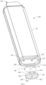
- FIG. 1 is a schematic diagram of an electronic atomization device 100 according to a specific embodiment.
- the electronic atomization device includes a plurality of components arranged in an outer body or a shell (which may be referred to as a housing).
- An overall design of the outer body or the shell is variable, and a style or configuration of an outer body that may limit an overall size and shape of the electronic atomization device 100 is variable.
- an elongated body may be formed by a single integral housing, or an elongated housing may be formed by two or more separable bodies.
- the electronic atomization device 100 may include a control body at an end, and the control body has a housing including one or more reusable components (for example, storage batteries such as rechargeable batteries and/or rechargeable supercapacitors, and various electronic components configured to control an operation of a product).
- the electronic atomization device includes an outer body or a shell for inhalation at an other end.
- the electronic atomization device 100 includes: a shell 10, basically defining an outer surface of the electronic atomization device 100 and including a near end 110 and a far end 120 opposite to each other in a longitudinal direction.
- the near end 110 is an end close to a user for inhalation; and the far end 120 is an end away from the user.
- the shell 10 may be formed by a metal such as stainless steel or aluminum, or an alloy.
- a metal such as stainless steel or aluminum, or an alloy.
- Other appropriate materials include various plastics (for example, polycarbonates), metal-plating over plastics, ceramics, and the like.
- the electronic atomization device 100 further includes: an inhalation port A, provided for the user to inhale; and the near end 110 located on the shell 10.
- the electronic atomization device 100 further includes: an operating element 80, arranged at the far end 120 of the shell 10 and arranged to be movable in a width direction of the shell 10. Specifically, a slot 121 extending in the width direction is provided at the far end 120 of the shell 10; and the operating element 80 is at least partially accommodated and held in the slot 121 to move.
- a limiting concave portion 125 extending in the width direction of the shell 10 is provided on a side edge of the slot 121; and an engaging protrusion 831 extending into the limiting concave portion 125 is arranged on the operating element 80, so that during movement, movement of the operating element 80 is limited by using the limiting concave portion 125.
- the operating element 80 is prevented from detaching from the slot 121.
- the operating element 80 is constructed to be substantially perpendicular to a longitudinal direction of the shell 10.
- the operating element 80 is thin, and a length of the operating element 80 is greater than a width, and the width is greater than a thickness.
- the operating element 80 includes a first end wall 810 and a second end wall 820 that face away from each other in a thickness direction, and a peripheral side wall 830 extending between the first end wall 810 and the second end wall 820.
- the engaging protrusion 831 is located on the peripheral side wall 830.
- the first end wall 810 of the operating element 80 faces the slot 121 of the shell 10 instead of being exposed, and the second end wall 820 is exposed at the far end 120 of the shell 10.
- a plurality of convex edges 821 are arranged on the second end wall 820, and are configured to provide friction when the user presses the second end wall 820 to move the operating element 80. This facilitates a user operation.
- the convex edge 821 is perpendicular to a length direction of the operating element 80.
- An accommodating concave cavity 811 is provided on the first end wall 810 of the operating element 80, and the accommodating concave cavity 811 is configured to accommodate and mount a damping element 90.
- the damping element 90 is made of elastic silicone, a thermoplastic elastomer, an elastic polymer, or the like. After assembly, the damping element 90 is located between the operating element 80 and the shell 10 in a longitudinal direction of the electronic atomization device, to provide damping during the movement of the operating element 80.
- the damping element 90 is also constructed to be thin. After assembly, the damping element 90 is compressed by the operating element 80 and the shell 10 on two sides in the thickness direction. A protrusion 91 is arranged on a surface of the damping element 90 facing the shell 10. This is beneficial for providing damping when the damping element abuts against the shell 10 to form extrusion or compression.
- the electronic atomization device 100 further includes: a liquid storage cavity 12 configured to store a liquid substrate, and an atomization assembly configured to absorb the liquid substrate from the liquid storage cavity 12 and heat and atomize the liquid substrate.
- both the liquid storage cavity 12 and the atomization assembly are arranged close to the near end 110.
- an aerosol output tube 11 is arranged in the longitudinal direction.
- the aerosol output tube 11 at least partially extends in the liquid storage cavity 12, and the liquid storage cavity 12 is formed by space between an outer wall of the aerosol output tube 11 and an inner wall of the first housing 10.
- a first end of the aerosol output tube 11 opposite to the near end 110 is in communication with the inhalation port A, to output the aerosol generated by the atomization assembly through atomization to the inhalation port A for inhalation.
- the atomization assembly includes:
- the liquid guide element 20 may be further constructed to be of various regular or irregular shapes, and is partially in fluid communication with the liquid storage cavity 12 to receive the liquid substrate.
- the liquid guide element 20 may be of more regular or irregular shapes, such as a polygonal block shape, a slot shape with a slot on a surface, or an arch shape with a hollow channel inside.
- the heating element 30 may be bonded onto the liquid guide element 20 through printing, deposition, sintering, physical assembly, or the like.
- the liquid guide element 20 may have a plane or a curved surface for supporting the heating element 30, and the heating element 30 is formed on the plane or the curved surface of the liquid guide element 20 through surface-mounting, printing, deposition, or the like.
- the heating element 30 is a conductive trajectory formed on a surface of the liquid guide element 20.
- the conductive trajectory of the heating element 30 may be in a form of a printed circuit formed through printing.
- the heating element 30 is a patterned conductive trajectory.
- the heating element 30 is planar.
- the heating element 30 is a conductive trajectory extending in a circuitous, meandering, reciprocating, or bending manner.
- a sealing element 40 is further arranged in the shell 10; and the sealing element 40 at least partially supports the aerosol output tube 11 and seals the liquid storage cavity 12.
- the liquid storage cavity 12 defined by the outer wall of the aerosol output tube 11 and the inner wall of the shell 10 is closed at an end portion close to the near end 110; and an end portion of the liquid storage cavity 12 facing the far end 120 is sealed by the sealing element 40.
- an insertion portion 41 extending toward the near end 110 is arranged on the sealing element 40, and is provided for insertion of the aerosol output tube 11.
- the sealing element 40 further defines an air channel 42 running through the sealing element 40 in the longitudinal direction of the electronic atomization device, to allow external air to enter the aerosol output tube 11 during inhalation. As shown in FIG. 7 , the air channel 42 is at least partially surrounded by the insertion portion 41.
- the electronic atomization device 100 further includes:
- a circuit board (not shown in the figure) is further arranged in the electronic atomization device 100, to control power output by the battery cell 140 to the heating element 30.
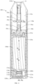
- FIG. 7 a design of an airflow path for inhalation is shown by an arrow R2.
- An air inlet is provided at the far end 120 of the electronic atomization device 100, to allow the external air to enter the shell 10 during inhalation.
- a gap is maintained between the battery cell 140 and the shell 10, so that the air entering from the air inlet can enter the air channel 42 of the sealing element 40 through the gap between the battery cell 140 and the shell 10, and then passes through the aerosol output tube 11 and carries the aerosol generated by the heating element 30 through heating to be output to the inhalation port A.
- the electronic atomization device 100 includes: an airflow sensor 150, such as a microphone or a differential pressure sensor, including a first side 151 and a second side 152 that face away from each other in the longitudinal direction of the electronic atomization device 100.
- an airflow sensor 150 such as a microphone or a differential pressure sensor
- the first side 151 is arranged to face the battery cell 140, and the first side 151 is in airflow communication with the gap between the battery cell 140 and the shell 10, so that an airflow flowing through the gap between the battery cell 140 and the shell 10 can be sensed during inhalation of the user.
- the second side 152 faces the far end 120, and can be in communication with an external atmosphere through a hole 124 located in the slot 121.
- the airflow sensor 150 determines an inhalation action of the user when a pressure difference between the first side 151 and the second side 152 caused by an inhalation airflow is greater than a preset threshold, and outputs a high-level signal. Further, the circuit board (not shown in the figure) controls, based on a sensing result of the airflow sensor 150, the battery cell 140 to output power to the heating element 30, to atomize a liquid to generate the aerosol.
- the electronic atomization device 100 includes: a first air inlet channel 170 located between the battery cell 140 and the far end 120.
- the first air inlet channel 170 includes a first air inlet 123 located in the slot 121.
- the first air inlet channel 170 is configured to allow the external air to enter the shell 10 from the first air inlet 123. Specifically, the external air is allowed to enter the gap between the battery cell 140 and the shell 10 from the first air inlet channel 170, to finally enter the aerosol output tube 11.
- the airflow sensor 150 is arranged close to the far end 120; and the airflow sensor 150 is arranged at the far end 120 close to the first air inlet 123.
- a first through hole 840 is provided on the operating element 80, and a second side 92 opposite to and in communication with the first through hole 840 is provided on the damping element 90.
- the operating element 80 is moved in the slot 121 by the user pressing the second end wall 820, and has a first configuration or a first location.
- FIG. 5 and FIG. 8 are schematic diagrams of the operating element 80 in the first configuration or the first location.
- the operating element 80 and the damping element 90 close the first air inlet 123 of the first air inlet channel 170.
- the operating element 80 and the damping element 90 close the hole 124.
- the second side 152 of the airflow sensor 150 is sealed or is isolated from the external air, so that the airflow sensor 150 such as the microphone or the differential pressure sensor, cannot be triggered.
- the circuit board controls to prevent the battery cell 140 from supplying power to the heating element 30, and the user cannot inhale.
- the external air cannot enter the shell 10 through the first air inlet 123. In this case, when the user inhales at the inhalation port A, there is large inhalation resistance because no inhalation airflow is generated.
- FIG. 6 and FIG. 9 are schematic diagrams of the operating element 80 in the second configuration or the second location.
- the operating element 80 and the damping element 90 open or expose the first air inlet 123 of the first air inlet channel 170.
- the hole 124 is aligned with both the first through hole 840 of the operating element 80 and the second through hole 92 of the damping element 90 to be in communication with the external air.
- the second side 152 of the airflow sensor 150 is in communication with the external air. In this way, in the second configuration and the second location, when the user inhales at the inhalation port A, the external air can enter the shell 10 through the first air inlet channel 170 in a direction shown by an arrow R4 in FIG.
- the airflow sensor 150 can be triggered based on that the pressure difference between the first side 151 and the second side 152 is greater than the preset threshold, so that the circuit board controls the battery cell 140 to supply power to the heating element 30 to generate the aerosol through heating.
- the first air inlet channel 170 and the hole 124 are selectively opened or closed through movement of the operating element 80 between the first configuration and the second configuration in a direction shown by an arrow P in FIG. 5 and FIG. 6 .
- the first air inlet channel 170 and the hole 124 are closed to form a locked state of the electronic atomization device 100.
- the heating element 30 is prevented from heating to generate the aerosol, and the inhalation resistance is made high during inhalation to prevent inhalation.
- the first air inlet channel 170 and the hole 124 are opened or conducted to form an unlocked state of the electronic atomization device 100. In this case, the user can inhale the aerosol.
- the foregoing electronic atomization device 100 can prevent the user, especially a minor, from inhaling through the locked state.
- the electronic atomization device 100 may detect a location of the operating element 80 by using a sensing device such as a distance sensor or an optical sensor, to determine a configuration state of the operating element 80; and prevent the aerosol from being generated in the first configuration.
- a sensing device such as a distance sensor or an optical sensor
- FIG. 10 to FIG. 15 show an electronic atomization device 100 according to a more preferred embodiment.
- the electronic atomization device 100 includes:
- the electronic atomization device 100 in this embodiment further includes:
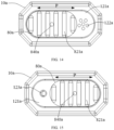
- FIG. 12 and FIG. 14 are schematic diagrams of the first configuration.
- the operating element 80a in the first configuration covers or closes the first air inlet 123a of the first air inlet channel 170a and the hole 124a, to prevent airflow sensor 150a from triggering to lock the electronic atomization device 100.
- the external air can enter the shell 10a from the second air inlet 122a of the second air inlet channel 160a, as shown by an arrow R3 in FIG. 12 ; and then the external air flows to the air channel 42a and the aerosol output tube 11a through the gap between the battery cell 140a and the shell 10a.
- the electronic atomization device 100 when the user inhales in a locked state, heating is not performed to generate the aerosol, but an airflow still pass through the electronic atomization device 100. In the locked state, air can still be inhaled without providing large inhalation resistance. This is beneficial to avoiding causing a minor to discover or find that the electronic atomization device 100 is locked.
- an area of the second air inlet 122a is greater than an area of the first air inlet 123a.
- the hole 124a is aligned with both a first through hole 840a of the operating element 80a and a second through hole 92a of the damping element 90a to be in communication with the external air.
- the first air inlet 123a of the first air inlet channel 170a is opened or exposed, and the external air can enter the shell 10a during inhalation in a direction shown by an arrow R4 in the figure.
- the electronic atomization device 100 is in an unlocked state, and when the user inhales, the airflow sensor 150a such as a microphone or a differential pressure sensor can respond to an inhalation action to trigger to generate a high-level signal, so that the circuit board controls, based on the triggering of the airflow sensor 150a, the battery cell 140a to output power to the heating element 30a.
- the airflow sensor 150a such as a microphone or a differential pressure sensor can respond to an inhalation action to trigger to generate a high-level signal, so that the circuit board controls, based on the triggering of the airflow sensor 150a, the battery cell 140a to output power to the heating element 30a.
- the second air inlet 122a of the second air inlet channel 160a is covered or closed, to prevent the external air from entering the shell 10a from the second air inlet channel 160a.
- generation of the aerosol is prevented in the locked state, but there is still an airflow passing through the electronic atomization device 100. This is beneficial to preventing the minor from discovering that the electronic atomization device 100 is locked.
- the air entering the shell 10a from the second air inlet channel 160a avoids the first side 151a of the airflow sensor 150a.
- the airflow during inhalation is separated from the first side 151a of the airflow sensor 150a. This is further beneficial to preventing the triggering of the airflow sensor 150a.
- a cross-sectional area of the first air inlet channel 170a is less than a cross-sectional area of the second air inlet channel 160a.
- a hole diameter of the second air inlet 122a is about 1 mm to 3 mm.
- both the first air inlet channel 170a and the second air inlet channel 160a extend in the longitudinal direction of the electronic atomization device 100; and the first air inlet channel 170a and the second air inlet channel 160a are arranged spaced away in a width direction of the electronic atomization device 100.
- the airflow sensor 150a is located between the first air inlet channel 170a and the second air inlet channel 160a in the width direction of the electronic atomization device 100.
- the airflow sensor 150a is close to a center of the electronic atomization device 100 in the width direction; and the first air inlet channel 170a and/or the second air inlet channel 160a deviates from the center of the electronic atomization device 100 in the width direction.
- the shell 10/10a of the electronic atomization device 100 is constructed to be in an elongated cylindrical shape different from the above flat shape.
- the operating element 80/80a is in an annular or arc shape that at least partially surrounds the shell 10/10a. In this way, correspondingly, in an operation, the operating element 80/80a is driven to rotate in a circumferential direction of the shell 10/10a, to adjust a location of the operating element 80/80 to be configured between the first configuration and the second configuration.
- the first air inlet channel 170/170a and the first air inlet 123/123a are correspondingly arranged at locations away from the far end 120/120a.
- the first air inlet channel 170/170a and the first air inlet 123/123a are located between the battery cell 140/140a and the sealing element 40/40a.
- the first air inlet channel 170/170a and the first air inlet 123/123a are defined between the holder 130/130a and the sealing element 40/40a. In this way, the operating element 80/80a is correspondingly adjusted and arranged at a corresponding location on the shell 10/10a.
- FIG. 16 to FIG. 23 show an electronic atomization device 100 according to another embodiment.
- a shell 10b of the electronic atomization device 100 includes a suction nozzle end and an opening end that are opposite to each other in a longitudinal direction, a part of the shell 10b adjacent to the suction nozzle end is configured to be a flat inhalation port B, a suction nozzle B 1 longitudinally penetrating through the inhalation port is provided inside the inhalation port B, and a user mainly contact the inhalation port B during use of the electronic atomization device 100.
- An atomization assembly and a battery 16b are mounted in an inner cavity of the shell 10b from the opening end of the shell 10b, and a bottom cover is further arranged at the opening end of the shell 10b. In addition to covering the opening end of the shell 10b, the bottom cover is further configured to provide longitudinal support for a battery assembly.
- a part of space of the inner cavity of the shell 10b is configured to be a liquid storage cavity 12b, and the liquid storage cavity 12b is configured to store a liquid substrate.
- the liquid storage cavity 12b is defined and formed by a liquid storage tube 121b fixed in the inner cavity of the shell 10b, the inner cavity of the liquid storage tube 121b is filled with a liquid storage element 122b, and the liquid storage element 122b may be defined and formed by fiber cotton having a liquid storage capability.
- the atomization assembly includes an atomization core assembly and the electronic atomization device 100 configured to support the atomization core assembly.
- the atomization core assembly includes a heating element 30b and a liquid guide element 20b.
- the heating element 30b is configured to atomize the liquid substrate to generate an aerosol.
- At least a part of the liquid guide element 20b is combined with the heating element 30b, and another part of the liquid guide element 20b extends into an inner part of the liquid storage cavity 12b or maintains a fluid channel with the liquid storage cavity 12b, to provide the liquid substrate inside the liquid storage cavity 12b for the heating element 30b.
- an atomization core assembly of the electronic atomization device 100 generally uses a low-cost cotton core atomization core assembly, a liquid guide element 20b thereof is made of a fiber cotton material, and a heating element 30b is made of one or more metals of iron, chromium, and nickel to form a spiral heating wire or a heating plate with a grid structure.
- the heating element 30b is configured to be a heating plate with a grid structure, the heating plate is constructed to be an open tubular structure, and the liquid guide element 20b is fixed to a periphery of the heating element 30b to wrap the heating element 30b in an inner cavity of the liquid guide element.
- the atomization core assembly is placed in the inner cavity of the shell 10b by using a substantially tubular holder 23b.
- the holder 23b has a cavity with two open ends, and two U-shaped openings penetrating through an upper open end of the holder are arranged on a side wall of the holder 23b.
- the liquid guide element 20b is generally formed by stacking several layers of fiber cotton sheets, and two free ends of the fiber cotton sheet are stacked together to form a protruding structure.
- the stacked several layers of fiber cotton sheets are fixed to a U-shaped opening 231b on the holder 23b by using the protruding structure.
- a step surface is arranged on an inner wall of the holder 23b, and a lower end of the liquid guide element 20b longitudinally abuts against the step surface of the inner wall.
- An upper end of the U-shaped opening 231b extends to the upper open end of the holder 23b, and a lower end of the U-shaped opening 231b is flush with the step surface.
- a liquid inlet hole 232b is further provided on the side wall of the holder 23b, and the liquid inlet hole 232b is provided within a longitudinal extension range of the U-shaped opening 231b.
- An air outlet tube 24b is sleeved on an upper end of the holder 23b, an end of the air outlet tube 24b abuts against a flange on an outer wall of the holder 23b, and the other end of the air outlet tube 24b extends out of the inner cavity of the liquid storage tube 121b.
- the liquid storage element 122b filled inside the liquid storage tube 121b is formed by splicing of several parts of fiber cotton, and the several parts of fiber cotton are spliced on the holder 23b and a periphery of the air outlet tube.
- the protruding structure on the liquid guide element 20b can directly contact with the fiber cotton, to absorb the liquid substrate.
- the liquid substrate can also enter the liquid guide element 20b from the liquid inlet hole on the holder 23b, and the heating element 30b atomizes the absorbed liquid substrate to generate the aerosol.
- the liquid storage cavity 12b of the electronic atomization device 100 is generally configured to be non-fillable, to prevent a user from adding a low-quality liquid substrate into the liquid storage cavity 12b.
- the liquid storage tube 121b includes a near end and a far end opposite to each other in the longitudinal direction, and the near end is arranged close to the inhalation port B.
- An upper sealing member 13b and a lower sealing member 14b are respectively arranged at the near end and the far end of the liquid storage tube 121b.
- the upper sealing sleeve is sealingly sleeved on an upper end of the liquid storage tube 121b.
- a slot is further provided on the upper sealing member 13b, and a liquid absorption element 131b is arranged in the slot.
- the liquid absorption element 131b is arranged close to the suction nozzle B1 and is made of a fiber cotton material with a capillary function, to absorb condensate and prevent the condensate from entering the suction nozzle B1 to be inhaled by the user.
- longitudinally penetrating fluid channels are provided on the liquid absorption element 131b and the upper sealing member 13b.
- a hollow air guide column 133b is provided on the upper sealing member 13b, the air guide column 133b is accommodated in an inner cavity of the air outlet tube 24b, and a vent hole on the air guide column 133b is in communication with the air outlet tube 24b and a vent hole on the liquid absorption element 131b.
- a flange is arranged on a side wall of the lower sealing member 14b, and a lower end of the liquid storage tube 121b abuts against the flange of the lower sealing member 14b.
- a through hole in communication with the slot is provided on the upper sealing member 13b.
- An upper end of the air outlet tube 24b is fixed in the through hole of the upper sealing member 13b, and an air outlet end of the air outlet tube 24b is arranged close to an air outlet hole on the liquid guide element 20b.
- the through hole on the upper sealing member 13b is in longitudinal communication with the air outlet tube and the vent hole on the liquid absorption element 131b.
- An air guide hole 141b is further provided on the lower sealing member 14b, and the air guide hole 141b is configured to be able to guide an external airflow into an inner cavity of the holder 23b.
- a lower end of the holder 23b abuts against a step surface on an inner wall of the air guide hole 141b.
- a positive electrode 142b and a negative electrode 143b are further fixed on the lower sealing member 14b.
- Conductive pins connected to two ends of the heating element 30b penetrate a wall of the lower sealing member 14b to be connected to the positive electrode 142b and the negative electrode 143b.
- the heating element 30b is configured to be a heating plate with a grid structure, and the heating plate is constructed to be an open tubular structure.
- Conductive leads connected to two ends of the heating element 30b are maintained to extend on a longitudinal extension line of two free sides of the heating plate as close as possible, to prevent the two free sides of the heating plate from being pulled, causing the heating plate to shift and affecting a heating effect of the heating plate.
- Several support legs 144b are arranged on a bottom end surface of the lower sealing member 14b, and the several support legs are arranged surrounding the air guide hole 141b. The support leg 144b abuts against a liquid absorption element or a power supply assembly in a bottom cover 81b.
- a control part of an airflow sensor 150b inside the electronic atomization device 100 is in communication with the power supply assembly through a wire, and the electronic atomization device 100 control, by using the airflow sensor 150b, opening and closing of the electronic atomization device 100 due to an air pressure change inside the shell 10b due to an inhalation action.
- the airflow sensor includes a first side 151b and a second side 152b.
- the first side 151b is in communication with the airflow channel inside the electronic atomization device 100
- the second side 152b is in communication with the external atmosphere through an air hole 50b.
- the airflow channel inside the electronic atomization device 100 is in communication with the suction nozzle B1 and an air inlet 60b.
- air pressure in the airflow channel inside the electronic atomization device 100 decreases, and a pressure difference is generated between the second side 152b and the first side 151b.
- the airflow sensor 150b converts a pressure difference signal into an electrical signal, to control the battery 16b to provide power drive for the atomization assembly.
- the air inlet 60b of the electronic atomization device 100 is generally provided at the bottom of the bottom cover thereof or near the bottom end thereof.
- the air hole 50b of the airflow sensor is also arranged close to the air inlet 60b.
- an operating element 70b is further arranged on an end of the shell 10b.
- the operating element 70b has a function of a child lock.
- the electronic atomization device 100 can be started only when the operating element 70b is adjusted to a set location. Further, the operating element 70b is configured to be movable between a first configuration and a second configuration relative to the shell 10b.
- the operating element 70b When the operating element 70b is in the first configuration, the operating element 70b is configured to simultaneously close the air hole 50b and the air inlet 60b, and the electronic atomization device 100 is in a locked state.
- the operating element 70b When the operating element 70b is in the second configuration, the operating element 70b is configured to simultaneously open the air hole 50b and the air inlet 60b, and the electronic atomization device 100 is in an open state.
- the electronic atomization device 100 When the electronic atomization device 100 is not in use, the electronic atomization device 100 is in a closed state, and the air inlet 60b and the air hole 50b of the electronic atomization device 100 are both in a closed state.
- a configuration of the operating element 70b mainly relies on a function of a movable switch.
- the movable switch may be configured to rotate relative to the shell 10b to implement the opening and closing of the electronic atomization device 100.
- the movable switch may alternatively be configured to slide relative to the shell 10b to implement the opening and closing of the electronic atomization device 100.
- a specific structure of the movable switch is described in detail below in combination with different structures of the electronic atomization device 100.
- the operating element 70b is configured to be a rotary switch.
- the atomization assembly and the power supply assembly inside the electronic atomization device 100 are arranged in parallel up and down, and the airflow sensor 150b is arranged at a lower end of the battery 16b.
- the electronic atomization device 100 includes a rotating sleeve 71b connected to an end of the shell 10b, where the rotating sleeve 71b may rotate relative to the shell 10b, and a sleeve 72b is further arranged inside the rotating sleeve 71b.
- the sleeve 72b is coaxially arranged with the rotating sleeve 71b, and an end of the sleeve 72b is fixedly connected to the shell 10b.
- the operating element 70b includes the rotating sleeve 71b and the sleeve 72b.
- the rotating sleeve 71b rotates relative to the sleeve 72b, thereby changing a switching state of the air inlet 60b and a switching state of the air hole 50b.
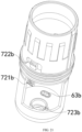
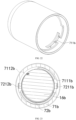
- the battery 16b is accommodated in an inner cavity of the sleeve 72b, a length of the sleeve 72b is greater than a length of the shell 10b, a circumferentially extending sliding rail 711b is arranged on an inner wall of the rotating sleeve 71b, and a first group of outward-turned buckles 721b is arranged on the sleeve 72b.
- the first group of buckles 721b is configured to be slidable on the sliding rail 711b, and the first group of buckles 721b includes a first buckle 7211b and a second buckle 7212b that are symmetrical about an axis thereof.
- a first sliding rail 7111b and a second sliding rail 7112b that are symmetrically arranged about a central axis of the rotating sleeve are arranged on the selected rotating sleeve 71b, where the first buckle 7211b slides on the first sliding rail 7111b, and the second buckle 7212b slides on the second sliding rail 7112b.
- a second group of buckles 722b is further arranged on the sleeve 72b, and the second group of buckles 722b is snap-connected to the shell 10b, so that the sleeve 72b is fixedly arranged inside the electronic atomization device 100.
- the rotating sleeve 71b When the rotating sleeve 71b is rotated in a specified direction, the rotating sleeve 71b rotates relative to the sleeve 72b until the buckle on the sleeve 72b abuts against an end of the sliding rail on the rotating sleeve 71b.
- a protrusion structure may be arranged on the inner wall of the rotating sleeve 71b
- a sliding slot structure may be arranged on the sleeve 72b, so that the rotating sleeve 71b is configured to be rotatable within a stroke limited by a sliding slot.
- the first group of buckles 721b on the sleeve 72b is located at an end of the sliding rail 711b.
- the first group of buckles 721b on the sleeve 72b is located at the other end of the sliding rail 711b.
- a receiving cavity 723 is provided on the sleeve 72b, and the airflow sensor 150b is fixed in the receiving cavity 723.
- a wire slot is provided on a side of the receiving cavity 723. A wire connected to a control board of the airflow sensor 150b is led out through the wire slot and further extends to be connected to the battery 16b and the heating element 30b.
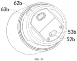
- the air inlet 60b includes at least one air inlet hole 61b provided at intervals at a bottom end of the rotating sleeve 71b, and an air guide port 62b is provided at a bottom end of the sleeve 72b.
- the air hole 50b includes a first air hole 51b provided at the bottom end of the rotating sleeve 71b and a second air hole 52b provided at the bottom end of the sleeve 72b.
- the second air hole 52b is in communication with the receiving cavity 723 of the airflow sensor 150b, where a part of the air inlet hole 61b and the first air hole 51b are arranged symmetrically about a center of the bottom end of the rotating sleeve 71b, so that during the rotation of the rotating sleeve 71b, a displacement of the air inlet hole 61b rotating relative to a central axis of the rotating sleeve is basically the same as a displacement of the first air hole 51b rotating relative to the central axis of the rotating sleeve, so that the air inlet hole 61b and the first air hole 51b can be simultaneously in communication with or staggered with the air guide port 62b and the second air hole 52b on the sleeve 72b respectively.
- a blocking element 73b is further arranged between the rotating sleeve 71b and the sleeve 72b.
- the blocking element 73b is configured to be a flexible material, so that the air inlet hole 61b and the first air hole 51b on the rotating sleeve 71b can be sealed and blocked, making it difficult for the airflow to enter through a gap between the two.
- a first air guide window 63b and a second air guide window 53b are further arranged on the blocking element 73b, and the first air guide window 63b and the second air guide window 53b are symmetrically arranged about a center of the blocking element 73b.
- the first air guide window 63b is always in communication with the air guide port 62b on the sleeve 72b.
- the rotating sleeve 71b is in the first configuration, the first air guide window 63b directly faces the air inlet hole 61b on the rotating sleeve 71b, and the airflow channel inside the electronic atomization device 100 is in longitudinal communication.
- the first air guide window 63b is completely staggered with the air inlet hole 61b on the rotating sleeve 71b, and the airflow channel inside the electronic atomization device 100 is in a closed state.
- the air hole 50b includes the second air guide window 53b, and the second air guide window 53b is always in communication with the second air hole 52b on the sleeve 72b.
- the second air guide window 53b directly faces the first air hole 51b on the rotating sleeve 71b, and the air hole 50b is in longitudinal communication.
- the second air guide window 53b is completely staggered with the first air hole 51b on the rotating sleeve 71b, and the air hole 50b is in a closed state.
- an air inlet cross-sectional area ofthe air inlet 60b of the electronic atomization device 100 is configured to be adjustable, so that inhalation resistance of the electronic atomization device 100 is configured to be in an adjustable mode.
- the electronic atomization device 100 is configured to be in a two-level inhalation resistance mode. As shown in FIG. 19 , two air inlet holes 61b, respectively a first air inlet hole 611b and a second air inlet hole 612b, are provided on an end of the rotating sleeve 71b.
- the first air inlet hole 611b is in longitudinal communication with the first air guide window 63b on the blocking element 73b and the air guide port 62b on the sleeve 72b, and the airflow channel is in a communication state.
- the second air inlet hole 612b is staggered with the first air guide window on the blocking element 73b, and the external airflow can only enter the electronic atomization device 100 through the first air inlet hole 611b. In this case, the electronic atomization device 100 is in a first inhalation resistance mode.
- the first air inlet hole 611b, the second air inlet hole 612b, the first air guide window 63b on the blocking element 73b, and the air guide port 62b on the sleeve 72b are all in longitudinal communication, and the external airflow may enter the electronic atomization device 100 through the first air inlet hole 611b and the second air inlet hole 612b.
- the electronic atomization device 100 is in a second inhalation resistance mode.
- an air inlet cross-sectional area limited by the air inlet 60b corresponding to the second inhalation resistance mode is much greater than an air inlet cross-sectional area limited by the air inlet 60b corresponding to the first inhalation resistance mode.
- the user may determine whether the electronic atomization device 100 is currently in the first inhalation resistance mode or the second inhalation resistance mode by observing a switching state of the first air inlet hole 611b and a switching state of the second air inlet hole 612b on the bottom cover.
- the third location is between the first configuration and the second configuration.
- the rotating sleeve 71b corresponds to a third location state.
- the air hole 50b is in an open state.
- the first air hole 51b on the rotating sleeve 71b, the second air guide window 53b on the blocking element 73b, and the second air hole 52b on the sleeve 72b are in a communication state.
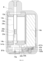
- an air inlet area of the second air guide window 53b is greater than an air inlet area of the second air hole 52b and an air inlet area of the first air hole 5 1b, so that when the rotating sleeve 71b moves from the third location to the second configuration, the second air hole 52b on the rotating sleeve 71b can always be in communication with the second air guide window 53b.
- An air inlet area of the first air guide window 63b is greater than an air inlet area of the first air inlet hole 611b and an air inlet area of the second air inlet hole 612b, so that during the rotation of the rotating sleeve 71b, the first air inlet hole 611b and the second air inlet hole 612b arranged spaced away on an end surface of the rotating sleeve 71b can simultaneously overlap with the first air guide window 63b.
- the air inlet area of the first air guide window 63b may be configured to be the same as an area of the air guide port 62b on the sleeve 72b, to further increase an airflow amount entering the electronic atomization device 100.
- the air inlet hole 61b provided on the rotating sleeve 71b may be provided to be an arc-shaped air inlet, so that during the rotation of the rotating sleeve 71b, an area of overlap between the arc-shaped air inlet on the rotating sleeve 71b and the first air guide window 63b on the blocking element 73b continuously changes, thereby continuously changing a size of the inhalation resistance of the electronic atomization device 100.
- the atomization assembly and the power supply assembly inside the electronic atomization device 100 are arranged side by side on the left and right.
- the inner cavity of the shell 10b of the electronic atomization device 100 is divided into two cavities, namely the liquid storage cavity 12b and a battery cavity.
- the inhalation port B is arranged within a range of a region in which the liquid storage cavity 12b extends, and the liquid storage cavity 12b and the battery cavity are separated by an inner wall of the shell 10b.
- the bottom cover 81b is arranged at an end of the shell 10b, and the airflow sensor 150b is fixedly arranged in an inner cavity of the bottom cover 81b.
- the box-shaped electronic atomization device 100 is configured with a large liquid storage cavity 12b, so that many liquid substrates can be stored inside.
- a charging interface 3 1b is further arranged on the bottom cover 81b, and the charging interface 3 1b is fixed on a charging plate.
- the charging plate is arranged at the lower end of the battery 16b.
- a receiving cavity is further provided in the inner cavity of the bottom cover 81b.
- the airflow sensor 150b is arranged closer to the atomization assembly than that in the foregoing embodiment, so that a protruding air guide column 431b is arranged at an end of the sealing sleeve 43b, an end of a vent hole on the air guide column 431b is in communication with the airflow channel inside the electronic atomization device 100, and the other end of the vent hole on the air guide column 431b is in communication with a sensing membrane of the airflow sensor 150b.
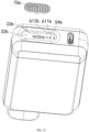
- the operating element 70b configured on the electronic atomization device 100 is configured to be a sliding switch 75b.
- a sliding slot 32b is provided on an end surface of the bottom cover 81b, a strip-shaped opening 33b is provided in the sliding slot 32b, and the sliding switch 75b includes an operating member and a protruding sliding column. An end of the sliding column is connected to the operating member, and a plug is arranged at the other end of the sliding column. Anti-slip grains are arranged on an outer surface of the operating member. When external force is applied to the operating member, the sliding switch 75b can slide in the sliding slot 32b, and an operable moving range of the sliding switch 75b is a stroke defined by the strip-shaped opening 33b of the sliding slot 32b.
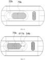
- the sliding column of the sliding switch 75b When the sliding switch 75b is in the first configuration, the sliding column of the sliding switch 75b is located at a side of the strip opening 33b, and when the sliding switch 75b is in the second configuration, the sliding column of the sliding switch 75b is located at the other side of the strip-shaped opening.
- the air inlet 60b of the electronic atomization device 100 includes the air inlet hole 61b provided on the sliding slot 32b, and the air hole 50b of the electronic atomization device 100 includes a third air hole 54b provided on the sliding slot 32b.
- the air inlet hole 61b is configured to introduce the external airflow into the inner cavity of the bottom cover 81b to enter the electronic atomization device 100.
- the first air hole 51b is in communication with the receiving cavity of the airflow sensor 150b, so that a base membrane of the airflow sensor 150b is in communication with the external atmosphere.
- the air inlet hole 61b is arranged adjacent to the third air hole 54b.
- the sliding switch 75b When the sliding switch 75b is in the first configuration, the third air hole 54b and the air inlet hole 61b are both blocked by the sliding switch 75b, as shown in FIG. 26 , so that the airflow channel and the air hole 50b of the electronic atomization device 100 are both in a closed state. Even if the user inhales hard, the external airflow cannot enter the electronic atomization device 100, and the airflow sensor 150b cannot be triggered, so that the electronic atomization device 100 is in a child lock state.
- the first air hole 51b is staggered with the sliding switch 75b, so that the air hole 50b of the electronic atomization device 100 is in an open state
- the air inlet hole 61b is staggered with the sliding switch 75b, so that the airflow channel of the electronic atomization device 100 is in an open state.
- the inhalation resistance of the electronic atomization device 100 is configured to be adjustable.
- two air inlet holes 61b respectively the first air inlet hole 611b and the second air inlet hole 612b, are provided spaced away in the sliding slot 32b.
- the third air hole 54b is provided on a side of the first air inlet hole 611b.
- the third air hole 54b, the first air inlet hole 611b, and the second air inlet hole 612b are provided adjacent to each other in sequence.
- the sliding switch 75b further includes the third location between the first configuration and the second configuration.
- the third air hole 54b is staggered with the sliding switch 75b
- the air hole 50b is in an open state
- the first air inlet hole 611b is staggered with the sliding switch 75b
- the second air inlet hole 612b is blocked by the sliding switch 75b
- the air inlet 60b is in an open state
- the electronic atomization device 100 corresponds to the first inhalation resistance mode, as shown in FIG. 27 .
- the first air hole 51b is staggered with the sliding switch 75b
- the air hole 50b is in an open state
- the first air inlet hole 611b and the second air inlet hole 612b are both staggered with the sliding switch 75b
- the air inlet 60b is in an open state
- the electronic atomization device 100 corresponds to the second inhalation resistance mode, as shown in FIG. 28 .
- the air inlet cross-sectional area defined by the air inlet 60b of the electronic atomization device 100 in the first inhalation resistance mode is smaller than the air inlet cross-sectional area defined by the air inlet 60b in the second inhalation resistance mode.
- the air inlet 60b may be configured to be a strip-shaped air inlet or a plurality of air inlet holes 61b may be provided on the sliding slot 32b, and a switching state of the plurality of air inlet holes 61b may be changed by changing a location of the sliding switch 75b, thereby adjusting the inhalation resistance of the electronic atomization device 100.
- An embodiment of this application provides an operating element 70b, and the operating element 70b can simultaneously control switching states of an air hole 50b and an air inlet 60b of an electronic atomization device 100.
- the operating element 70b When the operating element 70b is in a first configuration, the air hole 50b and the air inlet 60b are both in a closed state. Even if a user performs an inhalation action hard, inside the electronic atomization device 100 without supplement of an external airflow, a first side 151b of an airflow sensor 150b can only sense a slight airflow change, so that the airflow sensor 150b of the electronic atomization device 100 cannot be triggered.
- the external airflow may enter the electronic atomization device 100 through the air hole 50b and a gap between a connecting wire of the airflow sensor 150b and a wire fixing slot or a fixing hole, so that sufficient negative pressure is generated inside the electronic atomization device 100, so that the airflow sensor 150b is triggered and the electronic atomization device 100 is started.
- the operating element 70b may be arranged with a multi-level adjustment mode, to further adjust an inhalation resistance mode of the electronic atomization device 100, thereby improving user experience.
Landscapes
- Special Spraying Apparatus (AREA)
Abstract
Description
- This application claims priority to
Chinese Patent Application No. 202220888270.0, entitled "ELECTRONIC ATOMIZATION DEVICE" Chinese Patent Application 202220875734.4, entitled "AEROSOL GENERATION DEVICE", filed with the China National Intellectual Property Administration on April 15, 2022 - Embodiments of this application relate to the field of electronic atomization technologies, and in particular, to an electronic atomization device.
- Tobacco products (such as cigarettes and cigars) burn tobacco during use to produce tobacco smoke. Attempts are made to replace these tobacco-burning products by manufacturing products that release compounds without being burnt.
- An example of such a product is a heating device that releases a compound by heating rather than burning a material. For example, the material may be tobacco or other non-tobacco products. These non-tobacco products may include or not include nicotine. In another example, there are aerosol-providing articles, for example, so-called electronic atomization devices. These devices generally contain a liquid, and the liquid is heated to be vaporized, to generate an inhalable aerosol. The liquid may contain nicotine, and/or aromatics, and/or aerosol-generation substances (such as glycerin). In a known electronic atomization device, an airflow sensor senses an inhalation action of a user, and based on the sensing of the airflow sensor, the liquid is controlled to be vaporized to generate the aerosol.
- An embodiment of this application provides an electronic atomization device, including:
- a liquid storage cavity, configured to store a liquid substrate;
- an atomization assembly, configured to atomize the liquid substrate to generate an aerosol;
- an inhalation port;
- a first air inlet, and a first airflow channel located between the first air inlet and the inhalation port, where the first air inlet, the inhalation port, and the first airflow channel are arranged to define a first airflow path from the first air inlet through the atomization assembly to the inhalation port, to transmit the aerosol to the inhalation port;
- an airflow sensor, in airflow communication with the first airflow channel and configured to sense an airflow change in the first airflow channel;
- a battery cell, configured to supply power to the atomization assembly;
- a circuit, configured to control, based on a sensing result of the airflow sensor, the battery cell to supply power to the atomization assembly; and
- an operating element, arranged to be configurable between a first configuration and a second configuration, where the operating element closes or covers the first air inlet in the first configuration to prevent external air from entering through the first air inlet, and the operating element opens or exposes the first air inlet in the second configuration.
- In a more preferred implementation, the circuit is configured to prevent, when the operating element is in the first configuration, the battery cell from supplying power to the atomization assembly.
- In a more preferred implementation, the electronic atomization device further includes:
a second air inlet, and a second airflow channel located between the second air inlet and the inhalation port, where the second air inlet, the inhalation port, and the second airflow channel are arranged to define a second airflow path from the first air inlet to the inhalation port. - In a more preferred implementation, the operating element opens or exposes the second air inlet in the first configuration; and the operating element closes or covers the second air inlet in the second configuration, to prevent the external air from entering through the second air inlet.
- In a more preferred implementation, an area of the second air inlet is greater than an area of the first air inlet.
- In a more preferred implementation, the electronic atomization device further includes:
- a shell, at least partially defining a surface of the electronic atomization device, where
- at least a part of the operating element is exposed outside the shell and is constructed to be movable relative to the shell, to change a configuration between the first configuration and the second configuration.
- In a more preferred implementation, the electronic atomization device further includes:
a damping element, located between the operating element and the shell, to provide damping in movement of the operating element. - In a more preferred implementation, the airflow sensor includes a first side and a second side that face away from each other, where the first side is in airflow communication with the first airflow channel;
- an air hole is further provided on the shell, to communicate the second side with an external atmosphere;
- the operating element closes or covers the air hole in the first configuration, to isolate the second side from the external atmosphere, to prevent the airflow sensor from sensing the airflow change in the first airflow channel; and the operating element opens or exposes the air hole in the second configuration, to communicate the second side with the external atmosphere.
- In a more preferred implementation, the operating element prevents the airflow sensor from sensing the airflow change in the first airflow channel in the first configuration, and allows the airflow sensor to sense the airflow change in the first airflow channel in the second configuration.
- Another embodiment of this application further provides an electronic atomization device, including:
- a liquid storage cavity, configured to store a liquid substrate;
- an atomization assembly, configured to atomize the liquid substrate to generate an aerosol;
- an inhalation port;
- a first air inlet, and a first airflow channel located between the first air inlet and the inhalation port, where the first air inlet, the inhalation port, and the first airflow channel are arranged to define a first airflow path from the first air inlet through the atomization assembly to the inhalation port, to transmit the aerosol to the inhalation port;
- an airflow sensor, including a first side and a second side that face away from each other, where the first side is in airflow communication with the first airflow channel;
- an air hole, configured to communicate the second side with an external atmosphere;
- a battery cell, configured to supply power to the atomization assembly;
- a circuit, controlling, based on a sensing result of the airflow sensor, the battery cell to supply power to the atomization assembly; and
- an operating element, arranged to be configurable between a first configuration and a second configuration, where the operating element closes or covers the air hole in the first configuration, to isolate the second side from the external atmosphere, to prevent the airflow sensor from sensing the airflow change in the first airflow channel; and the operating element opens or exposes the air hole in the second configuration, to communicate the second side with the external atmosphere, to allow the airflow sensor to sense the airflow change in the first airflow channel.
- According to the foregoing electronic atomization device, the electronic atomization device is locked in the first configuration by using the operating element, to avoid providing the aerosol to a user, especially a minor.
- One or more embodiments are exemplarily described with reference to the corresponding figures in the accompanying drawings, and the descriptions are not to be construed as limiting the embodiments. Elements in the accompanying drawings that have same reference numerals are represented as similar elements, and unless otherwise particularly stated, the figures in the accompanying drawings are not drawn to scale.
-
FIG. 1 is a schematic diagram of an electronic atomization device from an angle of view according to an embodiment; -
FIG. 2 is a schematic diagram of the electronic atomization device inFIG. 1 from another angle of view; -
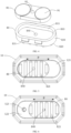
FIG. 3 is a schematic exploded view of a part of components of the electronic atomization device inFIG. 2 before assembly; -
FIG. 4 is a schematic exploded view of an operating element and a damping element inFIG. 3 from another angle of view; -
FIG. 5 is a schematic diagram of an operating element inFIG. 2 in a configuration state; -
FIG. 6 is a schematic diagram of the operating element inFIG. 5 moved to another configuration state; -
FIG. 7 is a schematic cross-sectional view of the electronic atomization device inFIG. 2 ; -
FIG. 8 is a schematic cross-sectional view of an operating element inFIG. 7 in a configuration state; -
FIG. 9 is a schematic cross-sectional view of the operating element inFIG. 8 moved to another configuration state; -
FIG. 10 is a schematic exploded view of a part of components of an electronic atomization device according to another embodiment; -
FIG. 11 is a schematic cross-sectional view of the electronic atomization device inFIG. 10 ; -
FIG. 12 is a schematic cross-sectional view of an operating element inFIG. 11 in a configuration state; -
FIG. 13 is a schematic cross-sectional view of the operating element inFIG. 12 moved to another configuration state; -
FIG. 14 is a schematic diagram of an operating element inFIG. 10 in a configuration state; -
FIG. 15 is a schematic diagram of the operating element inFIG. 14 moved to another configuration state; -
FIG. 16 is a cross-sectional view of an electronic atomization device according to another embodiment; -
FIG. 17 is an exploded view of an atomization assembly inFIG. 16 ; -
FIG. 18 is a cross-sectional view of the electronic atomization device inFIG. 16 from another angle of view; -
FIG. 19 is an exploded view of the electronic atomization device inFIG. 16 ; -
FIG. 20 is a three-dimensional diagram of the electronic atomization device inFIG. 16 with a rotating sleeve removed; -
FIG. 21 is a three-dimensional diagram of a sleeve of the electronic atomization device inFIG. 16 ; -
FIG. 22 is a three-dimensional diagram of the rotating sleeve of the electronic atomization device inFIG. 16 ; -
FIG. 23 is a cross-sectional view of the electronic atomization device inFIG. 16 from another angle of view; -
FIG. 24 is a cross-sectional view of an electronic atomization device according to another embodiment; -
FIG. 25 is an exploded view of the electronic atomization device inFIG. 24 ; -
FIG. 26 is a three-dimensional diagram of an operating element of the electronic atomization device inFIG. 24 in a first configuration; -
FIG. 27 is a three-dimensional diagram of the operating element of the electronic atomization device inFIG. 24 in a third configuration; and -
FIG. 28 is a three-dimensional diagram of the operating element of the electronic atomization device inFIG. 24 in a second configuration. - For ease of understanding of this application, this application is described in further detail below with reference to the accompanying drawings and specific implementations.
- This application provides an electronic atomization device, configured to atomize a liquid substrate to generate an aerosol.
- Further,
FIG. 1 is a schematic diagram of anelectronic atomization device 100 according to a specific embodiment. The electronic atomization device includes a plurality of components arranged in an outer body or a shell (which may be referred to as a housing). An overall design of the outer body or the shell is variable, and a style or configuration of an outer body that may limit an overall size and shape of theelectronic atomization device 100 is variable. Generally, an elongated body may be formed by a single integral housing, or an elongated housing may be formed by two or more separable bodies. - For example, the
electronic atomization device 100 may include a control body at an end, and the control body has a housing including one or more reusable components (for example, storage batteries such as rechargeable batteries and/or rechargeable supercapacitors, and various electronic components configured to control an operation of a product). In addition, the electronic atomization device includes an outer body or a shell for inhalation at an other end. - Further, in specific embodiments shown in
FIG. 1 and FIG. 2 , theelectronic atomization device 100 includes:
ashell 10, basically defining an outer surface of theelectronic atomization device 100 and including anear end 110 and afar end 120 opposite to each other in a longitudinal direction. During use, thenear end 110 is an end close to a user for inhalation; and thefar end 120 is an end away from the user. - In some examples, the
shell 10 may be formed by a metal such as stainless steel or aluminum, or an alloy. Other appropriate materials include various plastics (for example, polycarbonates), metal-plating over plastics, ceramics, and the like. - Further, as shown in
FIG. 1 and FIG. 2 , theelectronic atomization device 100 further includes:
an inhalation port A, provided for the user to inhale; and thenear end 110 located on theshell 10. - The
electronic atomization device 100 further includes:
anoperating element 80, arranged at thefar end 120 of theshell 10 and arranged to be movable in a width direction of theshell 10. Specifically, aslot 121 extending in the width direction is provided at thefar end 120 of theshell 10; and the operatingelement 80 is at least partially accommodated and held in theslot 121 to move. In addition, a limitingconcave portion 125 extending in the width direction of theshell 10 is provided on a side edge of theslot 121; and an engagingprotrusion 831 extending into the limitingconcave portion 125 is arranged on the operatingelement 80, so that during movement, movement of the operatingelement 80 is limited by using the limitingconcave portion 125. In addition, through cooperation between the limitingconcave portion 125 and the engagingprotrusion 831, the operatingelement 80 is prevented from detaching from theslot 121. - Further, as shown in
FIG. 3 andFIG. 4 , the operatingelement 80 is constructed to be substantially perpendicular to a longitudinal direction of theshell 10. The operatingelement 80 is thin, and a length of the operatingelement 80 is greater than a width, and the width is greater than a thickness. The operatingelement 80 includes afirst end wall 810 and asecond end wall 820 that face away from each other in a thickness direction, and aperipheral side wall 830 extending between thefirst end wall 810 and thesecond end wall 820. The engagingprotrusion 831 is located on theperipheral side wall 830. - After assembly, the
first end wall 810 of the operatingelement 80 faces theslot 121 of theshell 10 instead of being exposed, and thesecond end wall 820 is exposed at thefar end 120 of theshell 10. A plurality ofconvex edges 821 are arranged on thesecond end wall 820, and are configured to provide friction when the user presses thesecond end wall 820 to move the operatingelement 80. This facilitates a user operation. Theconvex edge 821 is perpendicular to a length direction of the operatingelement 80. - An accommodating
concave cavity 811 is provided on thefirst end wall 810 of the operatingelement 80, and the accommodatingconcave cavity 811 is configured to accommodate and mount a dampingelement 90. The dampingelement 90 is made of elastic silicone, a thermoplastic elastomer, an elastic polymer, or the like. After assembly, the dampingelement 90 is located between the operatingelement 80 and theshell 10 in a longitudinal direction of the electronic atomization device, to provide damping during the movement of the operatingelement 80. - Further, as shown in
FIG. 3 andFIG. 4 , the dampingelement 90 is also constructed to be thin. After assembly, the dampingelement 90 is compressed by the operatingelement 80 and theshell 10 on two sides in the thickness direction. Aprotrusion 91 is arranged on a surface of the dampingelement 90 facing theshell 10. This is beneficial for providing damping when the damping element abuts against theshell 10 to form extrusion or compression. - Further, as shown in
FIG. 5 to FIG. 9 , theelectronic atomization device 100 further includes:
aliquid storage cavity 12 configured to store a liquid substrate, and an atomization assembly configured to absorb the liquid substrate from theliquid storage cavity 12 and heat and atomize the liquid substrate. In addition, for ease of atomization and output, both theliquid storage cavity 12 and the atomization assembly are arranged close to thenear end 110. Specifically, in this embodiment, anaerosol output tube 11 is arranged in the longitudinal direction. In an implementation, theaerosol output tube 11 at least partially extends in theliquid storage cavity 12, and theliquid storage cavity 12 is formed by space between an outer wall of theaerosol output tube 11 and an inner wall of thefirst housing 10. A first end of theaerosol output tube 11 opposite to thenear end 110 is in communication with the inhalation port A, to output the aerosol generated by the atomization assembly through atomization to the inhalation port A for inhalation. - In an implementation shown in
FIG. 7 , the atomization assembly includes: - a
liquid guide element 20, made of a capillary material or a porous material, such as a sponge, a cotton fiber, or a porous body, where theliquid guide element 20 extends perpendicular to the longitudinal direction of theelectronic atomization device 100, and theliquid guide element 20 at least partially extends from theliquid storage cavity 12 into theaerosol output tube 11, to absorb and store the liquid substrate through capillary infiltration, as shown by an arrow R1 inFIG. 7 ; and - a
heating element 30, located in theaerosol output tube 11 and surrounding theliquid guide element 20, to heat at least a part of the liquid substrate in theliquid guide element 20 to generate the aerosol and release the aerosol to theaerosol output tube 11. In a preferred implementation, theheating element 30 is a spiral heating wire surrounding theliquid guide element 20. - Alternatively, in some variable implementations, the
liquid guide element 20 may be further constructed to be of various regular or irregular shapes, and is partially in fluid communication with theliquid storage cavity 12 to receive the liquid substrate. Alternatively, in some variable implementations, theliquid guide element 20 may be of more regular or irregular shapes, such as a polygonal block shape, a slot shape with a slot on a surface, or an arch shape with a hollow channel inside. - Alternatively, in some other variable implementations, the
heating element 30 may be bonded onto theliquid guide element 20 through printing, deposition, sintering, physical assembly, or the like. In some other variable implementations, theliquid guide element 20 may have a plane or a curved surface for supporting theheating element 30, and theheating element 30 is formed on the plane or the curved surface of theliquid guide element 20 through surface-mounting, printing, deposition, or the like. Alternatively, in some other variable implementations, theheating element 30 is a conductive trajectory formed on a surface of theliquid guide element 20. In an implementation, the conductive trajectory of theheating element 30 may be in a form of a printed circuit formed through printing. In some implementations, theheating element 30 is a patterned conductive trajectory. In some other implementations, theheating element 30 is planar. In the implementations, theheating element 30 is a conductive trajectory extending in a circuitous, meandering, reciprocating, or bending manner. - Further, as shown in
FIG. 7 , a sealingelement 40 is further arranged in theshell 10; and the sealingelement 40 at least partially supports theaerosol output tube 11 and seals theliquid storage cavity 12. In this way, after assembly, theliquid storage cavity 12 defined by the outer wall of theaerosol output tube 11 and the inner wall of theshell 10 is closed at an end portion close to thenear end 110; and an end portion of theliquid storage cavity 12 facing thefar end 120 is sealed by the sealingelement 40. - For ease of assembly, an
insertion portion 41 extending toward thenear end 110 is arranged on the sealingelement 40, and is provided for insertion of theaerosol output tube 11. The sealingelement 40 further defines anair channel 42 running through the sealingelement 40 in the longitudinal direction of the electronic atomization device, to allow external air to enter theaerosol output tube 11 during inhalation. As shown inFIG. 7 , theair channel 42 is at least partially surrounded by theinsertion portion 41. - Further, as shown in
FIG. 7 , theelectronic atomization device 100 further includes: - a
holder 130, located between the sealingelement 40 and thefar end 120, where theholder 130 is rigid and includes asupport arm 131, and thesupport arm 131 is inserted into the sealingelement 40 to provide support for the sealingelement 40; and - a
battery cell 140, at least partially accommodated and held in theholder 130, and configured to supply power to theheating element 30. Specifically, lead holes 43 are provided on the sealingelement 40, and after assembly, two ends of theheating element 30 are connected to thebattery cell 140 by using leading wires passing through the lead holes 43, so that theheating element 30 is in connection. - Certainly, a circuit board (not shown in the figure) is further arranged in the
electronic atomization device 100, to control power output by thebattery cell 140 to theheating element 30. - Further, as shown in
FIG. 7 , a design of an airflow path for inhalation is shown by an arrow R2. An air inlet is provided at thefar end 120 of theelectronic atomization device 100, to allow the external air to enter theshell 10 during inhalation. In addition, a gap is maintained between thebattery cell 140 and theshell 10, so that the air entering from the air inlet can enter theair channel 42 of the sealingelement 40 through the gap between thebattery cell 140 and theshell 10, and then passes through theaerosol output tube 11 and carries the aerosol generated by theheating element 30 through heating to be output to the inhalation port A. - Further, as shown in
FIG. 5 to FIG. 9 , theelectronic atomization device 100 includes:
anairflow sensor 150, such as a microphone or a differential pressure sensor, including afirst side 151 and asecond side 152 that face away from each other in the longitudinal direction of theelectronic atomization device 100. After assembly, thefirst side 151 is arranged to face thebattery cell 140, and thefirst side 151 is in airflow communication with the gap between thebattery cell 140 and theshell 10, so that an airflow flowing through the gap between thebattery cell 140 and theshell 10 can be sensed during inhalation of the user. Thesecond side 152 faces thefar end 120, and can be in communication with an external atmosphere through ahole 124 located in theslot 121. Theairflow sensor 150 determines an inhalation action of the user when a pressure difference between thefirst side 151 and thesecond side 152 caused by an inhalation airflow is greater than a preset threshold, and outputs a high-level signal. Further, the circuit board (not shown in the figure) controls, based on a sensing result of theairflow sensor 150, thebattery cell 140 to output power to theheating element 30, to atomize a liquid to generate the aerosol. - Further, as shown in
FIG. 5 to FIG. 9 , theelectronic atomization device 100 includes:
a firstair inlet channel 170 located between thebattery cell 140 and thefar end 120. The firstair inlet channel 170 includes afirst air inlet 123 located in theslot 121. The firstair inlet channel 170 is configured to allow the external air to enter theshell 10 from thefirst air inlet 123. Specifically, the external air is allowed to enter the gap between thebattery cell 140 and theshell 10 from the firstair inlet channel 170, to finally enter theaerosol output tube 11. - In addition, as shown in the figure, the
airflow sensor 150 is arranged close to thefar end 120; and theairflow sensor 150 is arranged at thefar end 120 close to thefirst air inlet 123. - Further, as shown in
FIG. 3 ,FIG. 4, FIG. 5, FIG. 6 ,FIG. 8, and FIG. 9 , a first throughhole 840 is provided on the operatingelement 80, and asecond side 92 opposite to and in communication with the first throughhole 840 is provided on the dampingelement 90. The operatingelement 80 is moved in theslot 121 by the user pressing thesecond end wall 820, and has a first configuration or a first location. Specifically, -
FIG. 5 andFIG. 8 are schematic diagrams of the operatingelement 80 in the first configuration or the first location. In the first configuration or the first location, the operatingelement 80 and the dampingelement 90 close thefirst air inlet 123 of the firstair inlet channel 170. In addition, in the first configuration or the first location, the operatingelement 80 and the dampingelement 90 close thehole 124. In this way, in the first configuration or the first location, thesecond side 152 of theairflow sensor 150 is sealed or is isolated from the external air, so that theairflow sensor 150 such as the microphone or the differential pressure sensor, cannot be triggered. In this way, in the first configuration or the first location, the circuit board controls to prevent thebattery cell 140 from supplying power to theheating element 30, and the user cannot inhale. In addition, in the implementations, the external air cannot enter theshell 10 through thefirst air inlet 123. In this case, when the user inhales at the inhalation port A, there is large inhalation resistance because no inhalation airflow is generated. -
FIG. 6 andFIG. 9 are schematic diagrams of the operatingelement 80 in the second configuration or the second location. In the second configuration or the second location, the operatingelement 80 and the dampingelement 90 open or expose thefirst air inlet 123 of the firstair inlet channel 170. In addition, thehole 124 is aligned with both the first throughhole 840 of the operatingelement 80 and the second throughhole 92 of the dampingelement 90 to be in communication with the external air. In this case, thesecond side 152 of theairflow sensor 150 is in communication with the external air. In this way, in the second configuration and the second location, when the user inhales at the inhalation port A, the external air can enter theshell 10 through the firstair inlet channel 170 in a direction shown by an arrow R4 inFIG. 9 ; and then the external air flows to theaerosol output tube 11 through the gap between thebattery cell 140 and theshell 10 in a direction shown by the arrow R2. In addition, theairflow sensor 150 can be triggered based on that the pressure difference between thefirst side 151 and thesecond side 152 is greater than the preset threshold, so that the circuit board controls thebattery cell 140 to supply power to theheating element 30 to generate the aerosol through heating. - The first
air inlet channel 170 and thehole 124 are selectively opened or closed through movement of the operatingelement 80 between the first configuration and the second configuration in a direction shown by an arrow P inFIG. 5 and FIG. 6 . Specifically, when the operating element is moved to the first configuration, the firstair inlet channel 170 and thehole 124 are closed to form a locked state of theelectronic atomization device 100. In this case, theheating element 30 is prevented from heating to generate the aerosol, and the inhalation resistance is made high during inhalation to prevent inhalation. When the operating element is moved to the second configuration, the firstair inlet channel 170 and thehole 124 are opened or conducted to form an unlocked state of theelectronic atomization device 100. In this case, the user can inhale the aerosol. Furthermore, the foregoingelectronic atomization device 100 can prevent the user, especially a minor, from inhaling through the locked state. - In some implementations, the
electronic atomization device 100 may detect a location of the operatingelement 80 by using a sensing device such as a distance sensor or an optical sensor, to determine a configuration state of the operatingelement 80; and prevent the aerosol from being generated in the first configuration. - Further,
FIG. 10 to FIG. 15 show anelectronic atomization device 100 according to a more preferred embodiment. In this implementation, theelectronic atomization device 100 includes: - a
shell 10a, including anear end 110a and afar end 120a that face away from to each other in a longitudinal direction, where anaerosol output tube 11a and aliquid storage cavity 12a close to thenear end 110a are provided in theshell 10a; - a
liquid guide element 20a, extending from theliquid storage cavity 12a into theaerosol output tube 11a, to absorb a liquid substrate; aheating element 30a, located in theaerosol output tube 11a and surrounding theliquid guide element 20a, to heat at least a part of the liquid substrate in theliquid guide element 20a to generate an aerosol; - a sealing
element 40a, sealing theliquid storage cavity 12a and having aninsertion portion 41a provided for insertion of theaerosol output tube 11a, where alead hole 43a is provided on the sealingelement 40a, and is provided for connecting theheating element 30a to abattery cell 140a after a leading wire passes through thelead hole 43a; and anair channel 42a is provided on the sealingelement 40a, to allow air entering from thefar end 120a to flow into theaerosol output tube 11a; - a
holder 130a, being rigid and including asupport arm 131a, where thesupport arm 131a is inserted into the sealingelement 40a to provide support for the sealingelement 40a; - the
battery cell 140a, accommodated and held in theholder 130a, and configured to output power to theheating element 30a; and - a circuit board (not shown in the figure), configured to control the
battery cell 140a to output power to theheating element 30a. - Further, as shown in
FIG. 12 to FIG. 15 , theelectronic atomization device 100 in this embodiment further includes: - an
airflow sensor 150a, where afirst side 151a is arranged to face thebattery cell 140a, and thefirst side 151a is in airflow communication with a gap between thebattery cell 140a and theshell 10a, so that an airflow flowing through the gap between thebattery cell 140a and theshell 10a can be sensed during inhalation of a user; and asecond side 152a faces thefar end 120a, and can be in communication with external air through ahole 124a located in aslot 121a; - a first
air inlet channel 170a, where the firstair inlet channel 170a includes afirst air inlet 123a located in theslot 121a; and the firstair inlet channel 170a is configured to allow the external air to enter theshell 10a from thefirst air inlet 123a, and specifically, the external air is allowed to enter the gap between thebattery cell 140a and theshell 10a from the firstair inlet channel 170a, to finally enter theaerosol output tube 11a; - a second
air inlet channel 160a, where the secondair inlet channel 160a includes asecond air inlet 122a located in theslot 121a; and the secondair inlet channel 160a is configured to allow the external air to enter theshell 10a from thesecond air inlet 122a; and - an
operating element 80a and a dampingelement 90a, located at thefar end 120a and movable in theslot 121a of theshell 10a, and selectively configured between a first configuration and a second configuration. Specifically, -
FIG. 12 andFIG. 14 are schematic diagrams of the first configuration. Theoperating element 80a in the first configuration covers or closes thefirst air inlet 123a of the firstair inlet channel 170a and thehole 124a, to preventairflow sensor 150a from triggering to lock theelectronic atomization device 100. - In addition, in the first configuration, when the user inhales at an inhalation port A, the external air can enter the
shell 10a from thesecond air inlet 122a of the secondair inlet channel 160a, as shown by an arrow R3 inFIG. 12 ; and then the external air flows to theair channel 42a and theaerosol output tube 11a through the gap between thebattery cell 140a and theshell 10a. In theelectronic atomization device 100 in this embodiment, when the user inhales in a locked state, heating is not performed to generate the aerosol, but an airflow still pass through theelectronic atomization device 100. In the locked state, air can still be inhaled without providing large inhalation resistance. This is beneficial to avoiding causing a minor to discover or find that theelectronic atomization device 100 is locked. - In addition, an area of the
second air inlet 122a is greater than an area of thefirst air inlet 123a. - Further, when the
operating element 80a and the dampingelement 90a are moved to the second configuration, as shown inFIG. 13 andFIG. 15 , thehole 124a is aligned with both a first throughhole 840a of theoperating element 80a and a second throughhole 92a of the dampingelement 90a to be in communication with the external air. Thefirst air inlet 123a of the firstair inlet channel 170a is opened or exposed, and the external air can enter theshell 10a during inhalation in a direction shown by an arrow R4 in the figure. In this case, theelectronic atomization device 100 is in an unlocked state, and when the user inhales, theairflow sensor 150a such as a microphone or a differential pressure sensor can respond to an inhalation action to trigger to generate a high-level signal, so that the circuit board controls, based on the triggering of theairflow sensor 150a, thebattery cell 140a to output power to theheating element 30a. - In addition, in the second configuration shown in
FIG. 13 andFIG. 15 , thesecond air inlet 122a of the secondair inlet channel 160a is covered or closed, to prevent the external air from entering theshell 10a from the secondair inlet channel 160a. - In the
electronic atomization device 100 in the preferred embodiment, generation of the aerosol is prevented in the locked state, but there is still an airflow passing through theelectronic atomization device 100. This is beneficial to preventing the minor from discovering that theelectronic atomization device 100 is locked. - In some other preferred implementations, in the locked state, when the user inhales, the air entering the
shell 10a from the secondair inlet channel 160a avoids thefirst side 151a of theairflow sensor 150a. Alternatively, in the locked state, the airflow during inhalation is separated from thefirst side 151a of theairflow sensor 150a. This is further beneficial to preventing the triggering of theairflow sensor 150a. - Further, according to the preferred implementations shown in
FIG. 12 and FIG. 13 , a cross-sectional area of the firstair inlet channel 170a is less than a cross-sectional area of the secondair inlet channel 160a. For the electronic atomization device inhaled by the minor in the locked state, this is beneficial to reducing the inhalation resistance to further prevent the minor from detecting that the electronic atomization device is locked. - Further, in the preferred implementation shown in
FIG. 14 , a hole diameter of thesecond air inlet 122a is about 1 mm to 3 mm. In addition, there are a plurality ofsecond air inlets 122a, for example, six second air inlets annularly arranged inFIG. 14 . - Further, in a more preferred implementation, both the first
air inlet channel 170a and the secondair inlet channel 160a extend in the longitudinal direction of theelectronic atomization device 100; and the firstair inlet channel 170a and the secondair inlet channel 160a are arranged spaced away in a width direction of theelectronic atomization device 100. In addition, theairflow sensor 150a is located between the firstair inlet channel 170a and the secondair inlet channel 160a in the width direction of theelectronic atomization device 100. - In addition, the
airflow sensor 150a is close to a center of theelectronic atomization device 100 in the width direction; and the firstair inlet channel 170a and/or the secondair inlet channel 160a deviates from the center of theelectronic atomization device 100 in the width direction. - Alternatively, in some other variable implementations, the
shell 10/10a of theelectronic atomization device 100 is constructed to be in an elongated cylindrical shape different from the above flat shape. The operatingelement 80/80a is in an annular or arc shape that at least partially surrounds theshell 10/10a. In this way, correspondingly, in an operation, the operatingelement 80/80a is driven to rotate in a circumferential direction of theshell 10/10a, to adjust a location of the operatingelement 80/80 to be configured between the first configuration and the second configuration. - Alternatively, in some other variable implementations, the first
air inlet channel 170/170a and thefirst air inlet 123/123a are correspondingly arranged at locations away from thefar end 120/120a. For example, in some implementations, the firstair inlet channel 170/170a and thefirst air inlet 123/123a are located between thebattery cell 140/140a and the sealingelement 40/40a. Alternatively, for example, in some implementations, the firstair inlet channel 170/170a and thefirst air inlet 123/123a are defined between theholder 130/130a and the sealingelement 40/40a. In this way, the operatingelement 80/80a is correspondingly adjusted and arranged at a corresponding location on theshell 10/10a. - Further,
FIG. 16 to FIG. 23 show anelectronic atomization device 100 according to another embodiment. In this implementation, ashell 10b of theelectronic atomization device 100 includes a suction nozzle end and an opening end that are opposite to each other in a longitudinal direction, a part of theshell 10b adjacent to the suction nozzle end is configured to be a flat inhalation port B, a suction nozzle B 1 longitudinally penetrating through the inhalation port is provided inside the inhalation port B, and a user mainly contact the inhalation port B during use of theelectronic atomization device 100. An atomization assembly and abattery 16b are mounted in an inner cavity of theshell 10b from the opening end of theshell 10b, and a bottom cover is further arranged at the opening end of theshell 10b. In addition to covering the opening end of theshell 10b, the bottom cover is further configured to provide longitudinal support for a battery assembly. A part of space of the inner cavity of theshell 10b is configured to be aliquid storage cavity 12b, and theliquid storage cavity 12b is configured to store a liquid substrate. In an example, theliquid storage cavity 12b is defined and formed by aliquid storage tube 121b fixed in the inner cavity of theshell 10b, the inner cavity of theliquid storage tube 121b is filled with aliquid storage element 122b, and theliquid storage element 122b may be defined and formed by fiber cotton having a liquid storage capability. - The atomization assembly includes an atomization core assembly and the
electronic atomization device 100 configured to support the atomization core assembly. The atomization core assembly includes aheating element 30b and aliquid guide element 20b. Theheating element 30b is configured to atomize the liquid substrate to generate an aerosol. At least a part of theliquid guide element 20b is combined with theheating element 30b, and another part of theliquid guide element 20b extends into an inner part of theliquid storage cavity 12b or maintains a fluid channel with theliquid storage cavity 12b, to provide the liquid substrate inside theliquid storage cavity 12b for theheating element 30b. For a non-rechargeableelectronic atomization device 100, an atomization core assembly of theelectronic atomization device 100 generally uses a low-cost cotton core atomization core assembly, aliquid guide element 20b thereof is made of a fiber cotton material, and aheating element 30b is made of one or more metals of iron, chromium, and nickel to form a spiral heating wire or a heating plate with a grid structure. - In an example, as shown in
FIG. 17 , theheating element 30b is configured to be a heating plate with a grid structure, the heating plate is constructed to be an open tubular structure, and theliquid guide element 20b is fixed to a periphery of theheating element 30b to wrap theheating element 30b in an inner cavity of the liquid guide element. The atomization core assembly is placed in the inner cavity of theshell 10b by using a substantiallytubular holder 23b. Theholder 23b has a cavity with two open ends, and two U-shaped openings penetrating through an upper open end of the holder are arranged on a side wall of theholder 23b. Theliquid guide element 20b is generally formed by stacking several layers of fiber cotton sheets, and two free ends of the fiber cotton sheet are stacked together to form a protruding structure. The stacked several layers of fiber cotton sheets are fixed to aU-shaped opening 231b on theholder 23b by using the protruding structure. A step surface is arranged on an inner wall of theholder 23b, and a lower end of theliquid guide element 20b longitudinally abuts against the step surface of the inner wall. An upper end of theU-shaped opening 231b extends to the upper open end of theholder 23b, and a lower end of theU-shaped opening 231b is flush with the step surface. Aliquid inlet hole 232b is further provided on the side wall of theholder 23b, and theliquid inlet hole 232b is provided within a longitudinal extension range of theU-shaped opening 231b. Anair outlet tube 24b is sleeved on an upper end of theholder 23b, an end of theair outlet tube 24b abuts against a flange on an outer wall of theholder 23b, and the other end of theair outlet tube 24b extends out of the inner cavity of theliquid storage tube 121b. Theliquid storage element 122b filled inside theliquid storage tube 121b is formed by splicing of several parts of fiber cotton, and the several parts of fiber cotton are spliced on theholder 23b and a periphery of the air outlet tube. The protruding structure on theliquid guide element 20b can directly contact with the fiber cotton, to absorb the liquid substrate. In addition, the liquid substrate can also enter theliquid guide element 20b from the liquid inlet hole on theholder 23b, and theheating element 30b atomizes the absorbed liquid substrate to generate the aerosol. - When the
electronic atomization device 100 reaches a factory state, theliquid storage cavity 12b of theelectronic atomization device 100 is generally configured to be non-fillable, to prevent a user from adding a low-quality liquid substrate into theliquid storage cavity 12b. Theliquid storage tube 121b includes a near end and a far end opposite to each other in the longitudinal direction, and the near end is arranged close to the inhalation port B. Anupper sealing member 13b and alower sealing member 14b are respectively arranged at the near end and the far end of theliquid storage tube 121b. The upper sealing sleeve is sealingly sleeved on an upper end of theliquid storage tube 121b. A slot is further provided on theupper sealing member 13b, and aliquid absorption element 131b is arranged in the slot. Theliquid absorption element 131b is arranged close to the suction nozzle B1 and is made of a fiber cotton material with a capillary function, to absorb condensate and prevent the condensate from entering the suction nozzle B1 to be inhaled by the user. In addition, longitudinally penetrating fluid channels are provided on theliquid absorption element 131b and theupper sealing member 13b. In an example, as shown inFIG. 16 andFIG. 17 , a hollowair guide column 133b is provided on theupper sealing member 13b, theair guide column 133b is accommodated in an inner cavity of theair outlet tube 24b, and a vent hole on theair guide column 133b is in communication with theair outlet tube 24b and a vent hole on theliquid absorption element 131b. A flange is arranged on a side wall of thelower sealing member 14b, and a lower end of theliquid storage tube 121b abuts against the flange of thelower sealing member 14b. In another example, as shown inFIG. 24 , a through hole in communication with the slot is provided on theupper sealing member 13b. An upper end of theair outlet tube 24b is fixed in the through hole of theupper sealing member 13b, and an air outlet end of theair outlet tube 24b is arranged close to an air outlet hole on theliquid guide element 20b. The through hole on theupper sealing member 13b is in longitudinal communication with the air outlet tube and the vent hole on theliquid absorption element 131b. - An
air guide hole 141b is further provided on thelower sealing member 14b, and theair guide hole 141b is configured to be able to guide an external airflow into an inner cavity of theholder 23b. A lower end of theholder 23b abuts against a step surface on an inner wall of theair guide hole 141b. Further, apositive electrode 142b and anegative electrode 143b are further fixed on thelower sealing member 14b. Conductive pins connected to two ends of theheating element 30b penetrate a wall of thelower sealing member 14b to be connected to thepositive electrode 142b and thenegative electrode 143b. In a preferred implementation, theheating element 30b is configured to be a heating plate with a grid structure, and the heating plate is constructed to be an open tubular structure. Conductive leads connected to two ends of theheating element 30b are maintained to extend on a longitudinal extension line of two free sides of the heating plate as close as possible, to prevent the two free sides of the heating plate from being pulled, causing the heating plate to shift and affecting a heating effect of the heating plate.Several support legs 144b are arranged on a bottom end surface of thelower sealing member 14b, and the several support legs are arranged surrounding theair guide hole 141b. Thesupport leg 144b abuts against a liquid absorption element or a power supply assembly in abottom cover 81b. - A control part of an
airflow sensor 150b inside theelectronic atomization device 100 is in communication with the power supply assembly through a wire, and theelectronic atomization device 100 control, by using theairflow sensor 150b, opening and closing of theelectronic atomization device 100 due to an air pressure change inside theshell 10b due to an inhalation action. The airflow sensor includes afirst side 151b and asecond side 152b. Thefirst side 151b is in communication with the airflow channel inside theelectronic atomization device 100, and thesecond side 152b is in communication with the external atmosphere through anair hole 50b. The airflow channel inside theelectronic atomization device 100 is in communication with the suction nozzle B1 and anair inlet 60b. When the user performs the inhalation action, air pressure in the airflow channel inside theelectronic atomization device 100 decreases, and a pressure difference is generated between thesecond side 152b and thefirst side 151b. When the pressure difference reaches a start threshold of theairflow sensor 150b, theairflow sensor 150b converts a pressure difference signal into an electrical signal, to control thebattery 16b to provide power drive for the atomization assembly. - For a one-piece
electronic atomization device 100, theair inlet 60b of theelectronic atomization device 100 is generally provided at the bottom of the bottom cover thereof or near the bottom end thereof. When theairflow sensor 150b is also arranged inside the bottom cover of theelectronic atomization device 100, theair hole 50b of the airflow sensor is also arranged close to theair inlet 60b. In the embodiment provided in this application, anoperating element 70b is further arranged on an end of theshell 10b. Theoperating element 70b has a function of a child lock. Theelectronic atomization device 100 can be started only when theoperating element 70b is adjusted to a set location. Further, theoperating element 70b is configured to be movable between a first configuration and a second configuration relative to theshell 10b. When theoperating element 70b is in the first configuration, theoperating element 70b is configured to simultaneously close theair hole 50b and theair inlet 60b, and theelectronic atomization device 100 is in a locked state. When theoperating element 70b is in the second configuration, theoperating element 70b is configured to simultaneously open theair hole 50b and theair inlet 60b, and theelectronic atomization device 100 is in an open state. When theelectronic atomization device 100 is not in use, theelectronic atomization device 100 is in a closed state, and theair inlet 60b and theair hole 50b of theelectronic atomization device 100 are both in a closed state. Therefore, even if a child imitates an inhalation action, the external airflow cannot enter theelectronic atomization device 100 through theair hole 50b or theair inlet 60b, so that thefirst side 151b and thesecond side 152b of theairflow sensor 150b inside theelectronic atomization device 100 cannot generate a pressure difference, so that theairflow sensor 150b cannot be triggered, and theelectronic atomization device 100 cannot generate the aerosol, thereby limiting use of theelectronic atomization device 100 by the child. A configuration of theoperating element 70b mainly relies on a function of a movable switch. The movable switch may be configured to rotate relative to theshell 10b to implement the opening and closing of theelectronic atomization device 100. In an optional implementation, the movable switch may alternatively be configured to slide relative to theshell 10b to implement the opening and closing of theelectronic atomization device 100. A specific structure of the movable switch is described in detail below in combination with different structures of theelectronic atomization device 100. - In an embodiment, when the
electronic atomization device 100 is configured to be in a cylindrical shape, theoperating element 70b is configured to be a rotary switch. When theelectronic atomization device 100 is configured to be in the cylindrical shape, the atomization assembly and the power supply assembly inside theelectronic atomization device 100 are arranged in parallel up and down, and theairflow sensor 150b is arranged at a lower end of thebattery 16b. As shown inFIG. 18 to FIG. 23 , theelectronic atomization device 100 includes arotating sleeve 71b connected to an end of theshell 10b, where therotating sleeve 71b may rotate relative to theshell 10b, and asleeve 72b is further arranged inside therotating sleeve 71b. Thesleeve 72b is coaxially arranged with therotating sleeve 71b, and an end of thesleeve 72b is fixedly connected to theshell 10b. Theoperating element 70b includes therotating sleeve 71b and thesleeve 72b. Therotating sleeve 71b rotates relative to thesleeve 72b, thereby changing a switching state of theair inlet 60b and a switching state of theair hole 50b. Further, thebattery 16b is accommodated in an inner cavity of thesleeve 72b, a length of thesleeve 72b is greater than a length of theshell 10b, a circumferentially extending slidingrail 711b is arranged on an inner wall of therotating sleeve 71b, and a first group of outward-turnedbuckles 721b is arranged on thesleeve 72b. The first group ofbuckles 721b is configured to be slidable on the slidingrail 711b, and the first group ofbuckles 721b includes afirst buckle 7211b and asecond buckle 7212b that are symmetrical about an axis thereof. Correspondingly, a first slidingrail 7111b and a second slidingrail 7112b that are symmetrically arranged about a central axis of the rotating sleeve are arranged on the selected rotatingsleeve 71b, where thefirst buckle 7211b slides on the first slidingrail 7111b, and thesecond buckle 7212b slides on the second slidingrail 7112b. A second group ofbuckles 722b is further arranged on thesleeve 72b, and the second group ofbuckles 722b is snap-connected to theshell 10b, so that thesleeve 72b is fixedly arranged inside theelectronic atomization device 100. When therotating sleeve 71b is rotated in a specified direction, therotating sleeve 71b rotates relative to thesleeve 72b until the buckle on thesleeve 72b abuts against an end of the sliding rail on therotating sleeve 71b. It may be understood that a protrusion structure may be arranged on the inner wall of therotating sleeve 71b, and a sliding slot structure may be arranged on thesleeve 72b, so that therotating sleeve 71b is configured to be rotatable within a stroke limited by a sliding slot. When therotating sleeve 71b is in the first configuration, the first group ofbuckles 721b on thesleeve 72b is located at an end of the slidingrail 711b. When therotating sleeve 71b is in the second configuration, the first group ofbuckles 721b on thesleeve 72b is located at the other end of the slidingrail 711b. A receiving cavity 723 is provided on thesleeve 72b, and theairflow sensor 150b is fixed in the receiving cavity 723. A wire slot is provided on a side of the receiving cavity 723. A wire connected to a control board of theairflow sensor 150b is led out through the wire slot and further extends to be connected to thebattery 16b and theheating element 30b. - The
air inlet 60b includes at least one air inlet hole 61b provided at intervals at a bottom end of therotating sleeve 71b, and anair guide port 62b is provided at a bottom end of thesleeve 72b. Theair hole 50b includes afirst air hole 51b provided at the bottom end of therotating sleeve 71b and asecond air hole 52b provided at the bottom end of thesleeve 72b. Thesecond air hole 52b is in communication with the receiving cavity 723 of theairflow sensor 150b, where a part of the air inlet hole 61b and thefirst air hole 51b are arranged symmetrically about a center of the bottom end of therotating sleeve 71b, so that during the rotation of therotating sleeve 71b, a displacement of the air inlet hole 61b rotating relative to a central axis of the rotating sleeve is basically the same as a displacement of thefirst air hole 51b rotating relative to the central axis of the rotating sleeve, so that the air inlet hole 61b and thefirst air hole 51b can be simultaneously in communication with or staggered with theair guide port 62b and thesecond air hole 52b on thesleeve 72b respectively. - Further, when the air inlet hole 61b on the
rotating sleeve 71b is staggered with theair guide port 62b on thesleeve 72b, and thefirst air hole 51b on therotating sleeve 71b is staggered with thesecond air hole 52b on thesleeve 72b, to form a seal between the air inlet hole 61b and the first air hole 5 1b on therotating sleeve 71b and prevent an airflow from entering through a gap between therotating sleeve 71b and thesleeve 72b, a blockingelement 73b is further arranged between therotating sleeve 71b and thesleeve 72b. When the air inlet hole 61b on therotating sleeve 71b is staggered with theair guide port 62b on thesleeve 72b, and thefirst air hole 51b on therotating sleeve 71b is staggered with thesecond air hole 52b on thesleeve 72b, the blockingelement 73b is configured to be a flexible material, so that the air inlet hole 61b and thefirst air hole 51b on therotating sleeve 71b can be sealed and blocked, making it difficult for the airflow to enter through a gap between the two. In addition, a firstair guide window 63b and a secondair guide window 53b are further arranged on the blockingelement 73b, and the firstair guide window 63b and the secondair guide window 53b are symmetrically arranged about a center of the blockingelement 73b. The firstair guide window 63b is always in communication with theair guide port 62b on thesleeve 72b. When therotating sleeve 71b is in the first configuration, the firstair guide window 63b directly faces the air inlet hole 61b on therotating sleeve 71b, and the airflow channel inside theelectronic atomization device 100 is in longitudinal communication. When therotating sleeve 71b is in the second configuration, the firstair guide window 63b is completely staggered with the air inlet hole 61b on therotating sleeve 71b, and the airflow channel inside theelectronic atomization device 100 is in a closed state. Theair hole 50b includes the secondair guide window 53b, and the secondair guide window 53b is always in communication with thesecond air hole 52b on thesleeve 72b. When therotating sleeve 71b is in the first configuration, the secondair guide window 53b directly faces thefirst air hole 51b on therotating sleeve 71b, and theair hole 50b is in longitudinal communication. When therotating sleeve 71b is in the second configuration, the secondair guide window 53b is completely staggered with thefirst air hole 51b on therotating sleeve 71b, and theair hole 50b is in a closed state. - Further, an air inlet cross-sectional area ofthe
air inlet 60b of theelectronic atomization device 100 is configured to be adjustable, so that inhalation resistance of theelectronic atomization device 100 is configured to be in an adjustable mode. In an example, theelectronic atomization device 100 is configured to be in a two-level inhalation resistance mode. As shown inFIG. 19 , two air inlet holes 61b, respectively a firstair inlet hole 611b and a secondair inlet hole 612b, are provided on an end of therotating sleeve 71b. When therotating sleeve 71b is at a third location, the firstair inlet hole 611b is in longitudinal communication with the firstair guide window 63b on the blockingelement 73b and theair guide port 62b on thesleeve 72b, and the airflow channel is in a communication state. The secondair inlet hole 612b is staggered with the first air guide window on the blockingelement 73b, and the external airflow can only enter theelectronic atomization device 100 through the firstair inlet hole 611b. In this case, theelectronic atomization device 100 is in a first inhalation resistance mode. When therotating sleeve 71b is in the second configuration, the firstair inlet hole 611b, the secondair inlet hole 612b, the firstair guide window 63b on the blockingelement 73b, and theair guide port 62b on thesleeve 72b are all in longitudinal communication, and the external airflow may enter theelectronic atomization device 100 through the firstair inlet hole 611b and the secondair inlet hole 612b. In this case, theelectronic atomization device 100 is in a second inhalation resistance mode. Apparently, an air inlet cross-sectional area limited by theair inlet 60b corresponding to the second inhalation resistance mode is much greater than an air inlet cross-sectional area limited by theair inlet 60b corresponding to the first inhalation resistance mode. The user may determine whether theelectronic atomization device 100 is currently in the first inhalation resistance mode or the second inhalation resistance mode by observing a switching state of the firstair inlet hole 611b and a switching state of the secondair inlet hole 612b on the bottom cover. The third location is between the first configuration and the second configuration. Correspondingly, when thefirst buckle 7211b and thesecond buckle 7212b are both at a middle location of the slidingrail 711b, therotating sleeve 71b corresponds to a third location state. In addition, when therotating sleeve 71b is at the third location, theair hole 50b is in an open state. To be specific, thefirst air hole 51b on therotating sleeve 71b, the secondair guide window 53b on the blockingelement 73b, and thesecond air hole 52b on thesleeve 72b are in a communication state. Therefore, an air inlet area of the secondair guide window 53b is greater than an air inlet area of thesecond air hole 52b and an air inlet area of the first air hole 5 1b, so that when therotating sleeve 71b moves from the third location to the second configuration, thesecond air hole 52b on therotating sleeve 71b can always be in communication with the secondair guide window 53b. An air inlet area of the firstair guide window 63b is greater than an air inlet area of the firstair inlet hole 611b and an air inlet area of the secondair inlet hole 612b, so that during the rotation of therotating sleeve 71b, the firstair inlet hole 611b and the secondair inlet hole 612b arranged spaced away on an end surface of therotating sleeve 71b can simultaneously overlap with the firstair guide window 63b. The air inlet area of the firstair guide window 63b may be configured to be the same as an area of theair guide port 62b on thesleeve 72b, to further increase an airflow amount entering theelectronic atomization device 100. It may be understood that the air inlet hole 61b provided on therotating sleeve 71b may be provided to be an arc-shaped air inlet, so that during the rotation of therotating sleeve 71b, an area of overlap between the arc-shaped air inlet on therotating sleeve 71b and the firstair guide window 63b on the blockingelement 73b continuously changes, thereby continuously changing a size of the inhalation resistance of theelectronic atomization device 100. - In another embodiment provided in this application, as shown in
FIG. 24 to FIG. 28 , when theelectronic atomization device 100 is configured to be in a box shape, the atomization assembly and the power supply assembly inside theelectronic atomization device 100 are arranged side by side on the left and right. In a preferred implementation, the inner cavity of theshell 10b of theelectronic atomization device 100 is divided into two cavities, namely theliquid storage cavity 12b and a battery cavity. The inhalation port B is arranged within a range of a region in which theliquid storage cavity 12b extends, and theliquid storage cavity 12b and the battery cavity are separated by an inner wall of theshell 10b. In the box-shapedelectronic atomization device 100, thebottom cover 81b is arranged at an end of theshell 10b, and theairflow sensor 150b is fixedly arranged in an inner cavity of thebottom cover 81b. Specifically, as shown inFIG. 24 andFIG. 25 , the box-shapedelectronic atomization device 100 is configured with a largeliquid storage cavity 12b, so that many liquid substrates can be stored inside. In a preferred implementation, a charging interface 3 1b is further arranged on thebottom cover 81b, and the charging interface 3 1b is fixed on a charging plate. The charging plate is arranged at the lower end of thebattery 16b. A receiving cavity is further provided in the inner cavity of thebottom cover 81b. After theairflow sensor 150b is fixed on a sealingsleeve 43b, an airflow sensing assembly is formed, and the airflow sensing assembly is fixed inside the receiving cavity. Theairflow sensor 150b is arranged closer to the atomization assembly than that in the foregoing embodiment, so that a protrudingair guide column 431b is arranged at an end of the sealingsleeve 43b, an end of a vent hole on theair guide column 431b is in communication with the airflow channel inside theelectronic atomization device 100, and the other end of the vent hole on theair guide column 431b is in communication with a sensing membrane of theairflow sensor 150b. Theoperating element 70b configured on theelectronic atomization device 100 is configured to be a slidingswitch 75b. A slidingslot 32b is provided on an end surface of thebottom cover 81b, a strip-shapedopening 33b is provided in the slidingslot 32b, and the slidingswitch 75b includes an operating member and a protruding sliding column. An end of the sliding column is connected to the operating member, and a plug is arranged at the other end of the sliding column. Anti-slip grains are arranged on an outer surface of the operating member. When external force is applied to the operating member, the slidingswitch 75b can slide in the slidingslot 32b, and an operable moving range of the slidingswitch 75b is a stroke defined by the strip-shapedopening 33b of the slidingslot 32b. When the slidingswitch 75b is in the first configuration, the sliding column of the slidingswitch 75b is located at a side of thestrip opening 33b, and when the slidingswitch 75b is in the second configuration, the sliding column of the slidingswitch 75b is located at the other side of the strip-shaped opening. - The
air inlet 60b of theelectronic atomization device 100 includes the air inlet hole 61b provided on the slidingslot 32b, and theair hole 50b of theelectronic atomization device 100 includes athird air hole 54b provided on the slidingslot 32b. The air inlet hole 61b is configured to introduce the external airflow into the inner cavity of thebottom cover 81b to enter theelectronic atomization device 100. Thefirst air hole 51b is in communication with the receiving cavity of theairflow sensor 150b, so that a base membrane of theairflow sensor 150b is in communication with the external atmosphere. The air inlet hole 61b is arranged adjacent to thethird air hole 54b. When the slidingswitch 75b is in the first configuration, thethird air hole 54b and the air inlet hole 61b are both blocked by the slidingswitch 75b, as shown inFIG. 26 , so that the airflow channel and theair hole 50b of theelectronic atomization device 100 are both in a closed state. Even if the user inhales hard, the external airflow cannot enter theelectronic atomization device 100, and theairflow sensor 150b cannot be triggered, so that theelectronic atomization device 100 is in a child lock state. When the slidingswitch 75b is in the second configuration, thefirst air hole 51b is staggered with the slidingswitch 75b, so that theair hole 50b of theelectronic atomization device 100 is in an open state, and the air inlet hole 61b is staggered with the slidingswitch 75b, so that the airflow channel of theelectronic atomization device 100 is in an open state. - Further, the inhalation resistance of the
electronic atomization device 100 is configured to be adjustable. Specifically, two air inlet holes 61b, respectively the firstair inlet hole 611b and the secondair inlet hole 612b, are provided spaced away in the slidingslot 32b. Thethird air hole 54b is provided on a side of the firstair inlet hole 611b. Thethird air hole 54b, the firstair inlet hole 611b, and the secondair inlet hole 612b are provided adjacent to each other in sequence. The slidingswitch 75b further includes the third location between the first configuration and the second configuration. When the slidingswitch 75b is at the third location, thethird air hole 54b is staggered with the slidingswitch 75b, theair hole 50b is in an open state, the firstair inlet hole 611b is staggered with the slidingswitch 75b, the secondair inlet hole 612b is blocked by the slidingswitch 75b, theair inlet 60b is in an open state, and theelectronic atomization device 100 corresponds to the first inhalation resistance mode, as shown inFIG. 27 . When the slidingswitch 75b is in the second configuration, thefirst air hole 51b is staggered with the slidingswitch 75b, theair hole 50b is in an open state, the firstair inlet hole 611b and the secondair inlet hole 612b are both staggered with the slidingswitch 75b, theair inlet 60b is in an open state, and theelectronic atomization device 100 corresponds to the second inhalation resistance mode, as shown inFIG. 28 . Apparently, the air inlet cross-sectional area defined by theair inlet 60b of theelectronic atomization device 100 in the first inhalation resistance mode is smaller than the air inlet cross-sectional area defined by theair inlet 60b in the second inhalation resistance mode. It may be understood that if it is necessary to add a multi-level inhalation resistance mode, theair inlet 60b may be configured to be a strip-shaped air inlet or a plurality of air inlet holes 61b may be provided on the slidingslot 32b, and a switching state of the plurality of air inlet holes 61b may be changed by changing a location of the slidingswitch 75b, thereby adjusting the inhalation resistance of theelectronic atomization device 100. - An embodiment of this application provides an
operating element 70b, and theoperating element 70b can simultaneously control switching states of anair hole 50b and anair inlet 60b of anelectronic atomization device 100. When theoperating element 70b is in a first configuration, theair hole 50b and theair inlet 60b are both in a closed state. Even if a user performs an inhalation action hard, inside theelectronic atomization device 100 without supplement of an external airflow, afirst side 151b of anairflow sensor 150b can only sense a slight airflow change, so that theairflow sensor 150b of theelectronic atomization device 100 cannot be triggered. It may be understood that if theair hole 50b is in an open state and the user inhales theelectronic atomization device 100, the external airflow may enter theelectronic atomization device 100 through theair hole 50b and a gap between a connecting wire of theairflow sensor 150b and a wire fixing slot or a fixing hole, so that sufficient negative pressure is generated inside theelectronic atomization device 100, so that theairflow sensor 150b is triggered and theelectronic atomization device 100 is started. After theair hole 50b is closed, the external airflow has no chance to enter theelectronic atomization device 100, so that there is no possibility that a child lock of theelectronic atomization device 100 fails. Further, theoperating element 70b may be arranged with a multi-level adjustment mode, to further adjust an inhalation resistance mode of theelectronic atomization device 100, thereby improving user experience. - It should be noted that, the specification of this application and the accompanying drawings thereof illustrate preferred embodiments of this application, but are not limited to the embodiments described in this specification. Further, a person of ordinary skill in the art may make improvements or variations according to the above descriptions, and such improvements and variations shall all fall within the protection scope of the appended claims of this application.
Claims (15)
- An electronic atomization device, comprising:a liquid storage cavity, configured to store a liquid substrate;an atomization assembly, configured to atomize the liquid substrate to generate an aerosol;an inhalation port;a first air inlet, and a first airflow channel located between the first air inlet and the inhalation port, wherein the first airflow channel defines a first airflow path from the first air inlet through the atomization assembly to the inhalation port, to transmit the aerosol to the inhalation port;an airflow sensor, in airflow communication with the first airflow channel and configured to sense an airflow change in the first airflow channel;a battery cell, configured to supply power to the atomization assembly;a circuit, configured to control, based on a sensing result of the airflow sensor, the battery cell to supply power to the atomization assembly; andan operating element, arranged to be configurable between a first configuration and a second configuration, wherein the operating element closes or covers the first air inlet in the first configuration to prevent external air from entering the first airflow channel through the first air inlet, and the operating element opens or exposes the first air inlet in the second configuration.
- The electronic atomization device according to claim 1, wherein the circuit is configured to prevent, when the operating element is in the first configuration, the battery cell from supplying power to the atomization assembly.
- The electronic atomization device according to claim 1 or 2, further comprising:
a second air inlet, and a second airflow channel located between the second air inlet and the inhalation port, wherein the second airflow channel defines a second airflow path from the first air inlet to the inhalation port. - The electronic atomization device according to claim 3, wherein the operating element opens or exposes the second air inlet in the first configuration; and the operating element closes or covers the second air inlet in the second configuration, to prevent the external air from entering the second airflow channel through the second air inlet.
- The electronic atomization device according to claim 3, wherein an area of the second air inlet is greater than an area of the first air inlet, or the number of the second air inlet is greater than the number of the first air inlet.
- The electronic atomization device according to claim 1 or 2, further comprising:
a shell, at least partially defining a surface of the electronic atomization device, wherein:
at least a part of the operating element is exposed outside the shell and is constructed to be movable relative to the shell, to change a configuration between the first configuration and the second configuration. - The electronic atomization device according to claim 6, further comprising:
a damping element, located between the operating element and the shell, to provide damping in movement of the operating element. - The electronic atomization device according to claim 6, wherein:the airflow sensor comprises a first side and a second side that face away from each other, and the first side is in airflow communication with the first airflow channel;an air hole is further provided on the shell, to communicate the second side with an external atmosphere;the operating element closes or covers the air hole in the first configuration, to isolate the second side from the external atmosphere, to prevent the airflow sensor from sensing the airflow change in the first airflow channel; andthe operating element opens or exposes the air hole in the second configuration, to communicate the second side with the external atmosphere.
- The electronic atomization device according to claim 1, wherein the operating element prevents the airflow sensor from sensing the airflow change in the first airflow channel in the first configuration, and allows the airflow sensor to sense the airflow change in the first airflow channel in the second configuration.
- The electronic atomization device according to claim 1, wherein the electronic atomization device further comprises a second air inlet, a configuration of the operating element further comprises a third configuration, the operating element opens the first air inlet and closes the second air inlet when in the third configuration, and the third configuration is located between the first configuration and the second configuration.
- The electronic atomization device according to claim 10, wherein the operating element simultaneously opens the first air inlet and the second air inlet when in the second configuration.
- An electronic atomization device, comprising:a shell;an inhalation port and at least one air inlet, wherein the air inlet is configured to guide an external airflow to enter the electronic atomization device, and an airflow channel is defined between the air inlet and the inhalation port;an airflow sensor, configured to sense an airflow change in the airflow channel, to generate a sensing signal, wherein the airflow sensor comprises a first side and a second side that are opposite to each other, and the first side is in fluid communication with the airflow channel;an air hole, configured to communicate the second side of the airflow sensor with an external world; andan operating element, wherein the operating element is movable relative to the shell between a first configuration and a second configuration; the operating element simultaneously closes the air hole and all the air inlets when in the first configuration, to prevent the sensing signal from being generated due to activation of the airflow sensor; and the operating element simultaneously opens the air hole and all the air inlets when in the second configuration, to allow the airflow sensor to be activated.
- The electronic atomization device according to claim 12, wherein an air inlet cross-sectional area of the air inlet is configured to be changeable with a change of a location of the operating element.
- The electronic atomization device according to claim 12, wherein the operating element is capable of being in a third configuration, the third configuration is located between the first configuration and the second configuration, and when the operating element is in the third configuration, the air hole is opened, and simultaneously the air inlet is partially opened or a partial quantity of air inlets are opened.
- The electronic atomization device according to claim 11, wherein:the operating element comprises a rotating sleeve, the rotating sleeve is connected to an end of the shell, and the rotating sleeve is configured to be rotatable relative to the shell;or the operating element comprises a sliding switch, and the sliding switch is configured to be operable to be slidable relative to the shell.
Applications Claiming Priority (3)
| Application Number | Priority Date | Filing Date | Title |
|---|---|---|---|
| CN202220888270.0U CN217446684U (en) | 2022-04-15 | 2022-04-15 | Electronic atomization device |
| CN202220875734.4U CN217826746U (en) | 2022-04-15 | 2022-04-15 | Aerosol generating device |
| PCT/CN2023/088549 WO2023198213A1 (en) | 2022-04-15 | 2023-04-15 | Electronic atomization device |
Publications (2)
| Publication Number | Publication Date |
|---|---|
| EP4487710A1 true EP4487710A1 (en) | 2025-01-08 |
| EP4487710A4 EP4487710A4 (en) | 2025-07-30 |
Family
ID=88329081
Family Applications (1)
| Application Number | Title | Priority Date | Filing Date |
|---|---|---|---|
| EP23787855.8A Pending EP4487710A4 (en) | 2022-04-15 | 2023-04-15 | ELECTRONIC ATOMIZATION DEVICE |
Country Status (3)
| Country | Link |
|---|---|
| US (1) | US20250248453A1 (en) |
| EP (1) | EP4487710A4 (en) |
| WO (1) | WO2023198213A1 (en) |
Families Citing this family (3)
| Publication number | Priority date | Publication date | Assignee | Title |
|---|---|---|---|---|
| CN119999969A (en) * | 2023-11-15 | 2025-05-16 | 深圳市合元科技有限公司 | Aerosol Generating Device |
| WO2026027722A1 (en) * | 2024-07-31 | 2026-02-05 | Philip Morris Products S.A. | Aerosol-generating device with a first airflow passage and a second airflow passage |
| CN118923948A (en) * | 2024-08-08 | 2024-11-12 | 深圳市吉迩科技有限公司 | Aerosol generating device |
Family Cites Families (13)
| Publication number | Priority date | Publication date | Assignee | Title |
|---|---|---|---|---|
| WO2012026963A2 (en) * | 2010-08-23 | 2012-03-01 | Darren Rubin | Systems and methods of aerosol delivery with airflow regulation |
| US10842195B2 (en) * | 2014-10-29 | 2020-11-24 | Jt International S.A. | Aerosol generating device |
| WO2016118645A1 (en) * | 2015-01-22 | 2016-07-28 | Fontem Holdings 1 B.V. | Electronic vaporization devices |
| KR20220002979A (en) * | 2019-05-03 | 2022-01-07 | 제이티 인터내셔널 소시에떼 아노님 | Aerosol-generating device with removable stopper with detector |
| CN111602857A (en) * | 2019-05-16 | 2020-09-01 | 深圳市艾维普思科技有限公司 | Pneumatic switch of electronic cigarette, power supply device of electronic cigarette and electronic cigarette |
| CN213939709U (en) * | 2020-07-28 | 2021-08-13 | 深圳市悦享未来电子有限公司 | Disposable electronic cigarette |
| CN111920097B (en) * | 2020-08-07 | 2025-10-24 | 深圳市卓力能技术有限公司 | An electronic atomization device |
| CN215958315U (en) * | 2021-07-21 | 2022-03-08 | 深圳市合元科技有限公司 | Atomizer, electronic atomization device and sealing element for atomizer |
| CN215958310U (en) * | 2021-01-29 | 2022-03-08 | 深圳市合元科技有限公司 | Atomizer and electronic atomization device |
| CN215347020U (en) * | 2021-03-11 | 2021-12-31 | 深圳市合元科技有限公司 | Atomizer and electronic atomization device |
| CN215347044U (en) * | 2021-05-07 | 2021-12-31 | 深圳市合元科技有限公司 | Atomizer and electronic atomization device |
| CN217826746U (en) * | 2022-04-15 | 2022-11-18 | 深圳市合元科技有限公司 | Aerosol generating device |
| CN217446684U (en) * | 2022-04-15 | 2022-09-20 | 深圳市合元科技有限公司 | Electronic atomization device |
-
2023
- 2023-04-15 US US18/855,686 patent/US20250248453A1/en active Pending
- 2023-04-15 WO PCT/CN2023/088549 patent/WO2023198213A1/en not_active Ceased
- 2023-04-15 EP EP23787855.8A patent/EP4487710A4/en active Pending
Also Published As
| Publication number | Publication date |
|---|---|
| US20250248453A1 (en) | 2025-08-07 |
| EP4487710A4 (en) | 2025-07-30 |
| WO2023198213A1 (en) | 2023-10-19 |
Similar Documents
| Publication | Publication Date | Title |
|---|---|---|
| US20250248453A1 (en) | Electronic atomization device | |
| CN217446684U (en) | Electronic atomization device | |
| EP4609734A1 (en) | Electronic atomization device, device body, and liquid source | |
| US12357022B2 (en) | Aerosol-generating device | |
| CN217826746U (en) | Aerosol generating device | |
| US20250248452A1 (en) | Electronic atomization device | |
| CN220712901U (en) | Electronic atomizing device | |
| EP4305982B1 (en) | Vaporization device and electronic cigarette having same | |
| EP4458183A1 (en) | Electronic atomization device and support for electronic atomization device | |
| EP4684666A1 (en) | Electronic atomization device | |
| EP4335313A1 (en) | Atomizer and electronic atomization device | |
| KR102326001B1 (en) | Cartridge and Aerosol generating device including the same | |
| CN217446683U (en) | Electronic atomization device | |
| CN219353095U (en) | Electronic atomizing device | |
| EP4599717A1 (en) | Atomizer and electronic atomization device | |
| WO2025011436A1 (en) | Electronic atomization device | |
| CN115836747A (en) | Atomizer, electronic atomization device and atomization assembly for atomizer | |
| WO2025066812A1 (en) | Electronic atomization device | |
| CN213939709U (en) | Disposable electronic cigarette | |
| CN219353090U (en) | Atomizer and electronic atomization device | |
| CN117044994A (en) | Nebulizers and aerosol generating devices | |
| CN221653642U (en) | Electronic atomizing device | |
| CN224192928U (en) | Electronic atomizing device | |
| WO2025092507A1 (en) | Electronic atomization device | |
| EP4643683A1 (en) | Atomizer and electronic atomization device |
Legal Events
| Date | Code | Title | Description |
|---|---|---|---|
| STAA | Information on the status of an ep patent application or granted ep patent |
Free format text: STATUS: THE INTERNATIONAL PUBLICATION HAS BEEN MADE |
|
| PUAI | Public reference made under article 153(3) epc to a published international application that has entered the european phase |
Free format text: ORIGINAL CODE: 0009012 |
|
| STAA | Information on the status of an ep patent application or granted ep patent |
Free format text: STATUS: REQUEST FOR EXAMINATION WAS MADE |
|
| 17P | Request for examination filed |
Effective date: 20240930 |
|
| AK | Designated contracting states |
Kind code of ref document: A1 Designated state(s): AL AT BE BG CH CY CZ DE DK EE ES FI FR GB GR HR HU IE IS IT LI LT LU LV MC ME MK MT NL NO PL PT RO RS SE SI SK SM TR |
|
| DAV | Request for validation of the european patent (deleted) | ||
| DAX | Request for extension of the european patent (deleted) | ||
| A4 | Supplementary search report drawn up and despatched |
Effective date: 20250626 |
|
| RIC1 | Information provided on ipc code assigned before grant |
Ipc: A24F 40/40 20200101AFI20250620BHEP Ipc: A24F 40/51 20200101ALI20250620BHEP Ipc: A24F 40/48 20200101ALI20250620BHEP Ipc: A24F 40/10 20200101ALI20250620BHEP |