EP4486063A1 - Stroboscope for loom - Google Patents
Stroboscope for loom Download PDFInfo
- Publication number
- EP4486063A1 EP4486063A1 EP23756100.6A EP23756100A EP4486063A1 EP 4486063 A1 EP4486063 A1 EP 4486063A1 EP 23756100 A EP23756100 A EP 23756100A EP 4486063 A1 EP4486063 A1 EP 4486063A1
- Authority
- EP
- European Patent Office
- Prior art keywords
- loom
- change
- stroboscope
- delay angle
- control unit
- Prior art date
- Legal status (The legal status is an assumption and is not a legal conclusion. Google has not performed a legal analysis and makes no representation as to the accuracy of the status listed.)
- Pending
Links
Images


Classifications
-
- D—TEXTILES; PAPER
- D03—WEAVING
- D03D—WOVEN FABRICS; METHODS OF WEAVING; LOOMS
- D03D47/00—Looms in which bulk supply of weft does not pass through shed, e.g. shuttleless looms, gripper shuttle looms, dummy shuttle looms
- D03D47/28—Looms in which bulk supply of weft does not pass through shed, e.g. shuttleless looms, gripper shuttle looms, dummy shuttle looms wherein the weft itself is projected into the shed
- D03D47/30—Looms in which bulk supply of weft does not pass through shed, e.g. shuttleless looms, gripper shuttle looms, dummy shuttle looms wherein the weft itself is projected into the shed by gas jet
- D03D47/3066—Control or handling of the weft at or after arrival
- D03D47/3073—Detection means therefor
-
- D—TEXTILES; PAPER
- D03—WEAVING
- D03D—WOVEN FABRICS; METHODS OF WEAVING; LOOMS
- D03D47/00—Looms in which bulk supply of weft does not pass through shed, e.g. shuttleless looms, gripper shuttle looms, dummy shuttle looms
- D03D47/28—Looms in which bulk supply of weft does not pass through shed, e.g. shuttleless looms, gripper shuttle looms, dummy shuttle looms wherein the weft itself is projected into the shed
- D03D47/30—Looms in which bulk supply of weft does not pass through shed, e.g. shuttleless looms, gripper shuttle looms, dummy shuttle looms wherein the weft itself is projected into the shed by gas jet
- D03D47/3093—Displaying data
-
- D—TEXTILES; PAPER
- D03—WEAVING
- D03J—AUXILIARY WEAVING APPARATUS; WEAVERS' TOOLS; SHUTTLES
- D03J1/00—Auxiliary apparatus combined with or associated with looms
- D03J1/005—Displays or displaying data
-
- H—ELECTRICITY
- H05—ELECTRIC TECHNIQUES NOT OTHERWISE PROVIDED FOR
- H05B—ELECTRIC HEATING; ELECTRIC LIGHT SOURCES NOT OTHERWISE PROVIDED FOR; CIRCUIT ARRANGEMENTS FOR ELECTRIC LIGHT SOURCES, IN GENERAL
- H05B47/00—Circuit arrangements for operating light sources in general, i.e. where the type of light source is not relevant
- H05B47/10—Controlling the light source
- H05B47/105—Controlling the light source in response to determined parameters
-
- G—PHYSICS
- G03—PHOTOGRAPHY; CINEMATOGRAPHY; ANALOGOUS TECHNIQUES USING WAVES OTHER THAN OPTICAL WAVES; ELECTROGRAPHY; HOLOGRAPHY
- G03B—APPARATUS OR ARRANGEMENTS FOR TAKING PHOTOGRAPHS OR FOR PROJECTING OR VIEWING THEM; APPARATUS OR ARRANGEMENTS EMPLOYING ANALOGOUS TECHNIQUES USING WAVES OTHER THAN OPTICAL WAVES; ACCESSORIES THEREFOR
- G03B15/00—Special procedures for taking photographs; Apparatus therefor
- G03B15/02—Illuminating scene
- G03B15/03—Combinations of cameras with lighting apparatus; Flash units
- G03B15/05—Combinations of cameras with electronic flash apparatus; Electronic flash units
-
- G—PHYSICS
- G03—PHOTOGRAPHY; CINEMATOGRAPHY; ANALOGOUS TECHNIQUES USING WAVES OTHER THAN OPTICAL WAVES; ELECTROGRAPHY; HOLOGRAPHY
- G03B—APPARATUS OR ARRANGEMENTS FOR TAKING PHOTOGRAPHS OR FOR PROJECTING OR VIEWING THEM; APPARATUS OR ARRANGEMENTS EMPLOYING ANALOGOUS TECHNIQUES USING WAVES OTHER THAN OPTICAL WAVES; ACCESSORIES THEREFOR
- G03B39/00—High-speed photography
Definitions
- the present invention relates to a loom stroboscope.
- a stroboscope is used for observing a loom.
- a loom stroboscope used for observing a loom includes a light emitting device, a trigger control unit, and an input unit.
- the trigger control unit is configured to transmit a trigger signal to the light emitting device to cause the light emitting device to emit light when a main shaft of the loom rotates by a delay angle from a reference angle.
- the input unit is operated by an observer to set a desired delay angle.
- Patent Literature 1 Japanese Examined Patent Publication No. H06-9158
- the suitable delay angle facilitates the observation of the loom. Accordingly, the observer adjusts the delay angle to obtain the suitable delay angle.
- the adjustment of the delay angle includes the following steps. First, the observer operates the input unit to set a conceivable suitable delay angle. The observer then observes the loom by using the set delay angle. If the set delay angle is not suitable for observing the loom, the observer operates the input unit to change the delay angle. The observer observes the loom by using the changed delay angle. If the changed delay angle is not suitable, the observer operates the input unit to change the delay angle again. In such a way, the observer repeats input of the delay angle and eye observation of the loom to adjust the delay angle, which decreases work efficiency.
- a loom stroboscope for solving the previously described problem includes: a light emitting device; and a trigger control unit configured to transmit a trigger signal to the light emitting device to cause the light emitting device to emit light when a main shaft of a loom rotates by a delay angle from a reference angle, wherein the trigger control unit is configured to change the delay angle by a predetermined amount of change within a predetermined range of change.
- the trigger control unit changes the delay angle by the predetermined amount of change within the predetermined range of change, the observer does not have to input the delay angle every time to change the delay angle. This therefore improves efficiency in the adjustment of the delay angle.
- the loom stroboscope may include an input unit for inputting the predetermined range of change and the predetermined amount of change.
- This configuration allows the observer to operate the input unit to set the desired range of change and the desired amount of change.
- the loom stroboscope may include a camera that is configured to capture an image in synchronization with light emission of the light emitting device.
- This configuration allows capturing images that show the condition of the loom at various delay angles.
- the loom stroboscope may include an image display for displaying the image captured by the camera.
- the trigger control unit of the loom stroboscope may be configured to repeatedly change the delay angle by the predetermined amount of change within the predetermined range of change.
- the loom operates at a high speed. Accordingly, the eye observation of a weft yarn may fail unless the trigger control unit repeatedly changes the delay angle. However, the trigger control unit repeatedly changes the delay angle, so that the eye observation is facilitated.
- the present invention which has been made in light of the above described problem, is directed to providing a loom stroboscope that allows efficient adjustment of a delay angle.
- the loom stroboscope is a stroboscope used for observation of a loom.
- the observation of the loom is to observe the travelling condition of a weft yarn.
- a loom 100 of the present embodiment is an air jet loom that uses air to insert a weft yarn.
- the loom 100 includes a main shaft 101 and a nozzle (not illustrated) from which a weft yarn is injected.
- the main shaft 101 is driven by a main motor (not illustrated).
- the timing at which the weft yarn is injected from the nozzle corresponds to a rotation angle of the main shaft 101.
- the weft yarn is injected from the nozzle when the main shaft 101 rotates by a predetermined rotation angle from a particular rotation angle.
- the particular rotation angle of the main shaft 101 is referred to as a reference angle.
- an angle delayed from the reference angle is referred to as a delay angle.
- the loom 100 includes a detecting unit 102 and an output unit 103.
- the detecting unit 102 is configured to detect the rotation angle of the main shaft 101.
- the detecting unit 102 is, for example, a rotary encoder.
- the detecting unit 102 is connected to the output unit 103.
- the detecting unit 102 transmits a detected rotation angle of the main shaft 101 to the output unit 103.
- the output unit 103 transmits a signal to the loom stroboscope every time the detected rotation angle corresponds to a predetermined reference angle. For example, if the reference angle is 0°, the output unit 103 outputs a signal every time the rotation angle of the main shaft 101 becomes 0°.
- a loom stroboscope 10 includes a light emitting device 11, a camera 12, a controller 13, an input unit 14, and a display 15.
- the light emitting device 11 is, for example, an LED light.
- the light emitting device 11 is disposed on a surface of a housing (not illustrated) of the loom stroboscope 10.
- the light emitting device 11 is connected to a trigger control unit 13a of the controller 13.
- the trigger control unit 13a will be described later.
- the light emitting device 11 emits light upon receiving a trigger signal from the trigger control unit 13a.
- the camera 12 is an imaging device.
- the camera 12 includes an image sensor.
- the camera 12 is disposed on the surface of the housing so that the camera 12 captures images of an object illuminated by the light emitting device 11.
- the camera 12 is connected to the trigger control unit 13a.
- the camera 12 is configured to capture an image upon receiving a trigger signal from the trigger control unit 13a.
- the loom stroboscope 10 is arranged so that the light emitting device 11 illuminates the weft yarn and the camera 12 captures images of the weft yarn in the loom 100.
- the loom stroboscope 10 may be fixed at a desired position with a fixing device (not illustrated).
- the controller 13 includes a processor and a storage unit.
- the processor is a Central Processing Unit (CPU), a Graphics Processing Unit (GPU), or a Digital Signal Processor (DSP).
- the storage unit includes Random Access Memory (RAM) and Read Only Memory (ROM).
- the storage unit stores program code or instructions for causing the processor to execute the processing.
- the storage unit i.e., a computer-readable medium, includes any available medium accessible by a general-purpose or dedicated computer.
- the controller 13 may include a hardware circuit, such as an Application Specific Integrated Circuit (ASIC) or a Field Programmable Gate Array (FPGA).
- the controller 13, which is a processing circuit may include one or more processors operating in accordance with a computer program, one or more hardware circuits, such as ASICs and FPGAs, or combinations thereof.
- the controller 13 includes the trigger control unit 13a for controlling a trigger signal and a display control unit 13b for controlling the display 15.
- the trigger signal of the present embodiment is a signal for causing the light emitting device 11 to emit light and the camera 12 to capture an image.
- the trigger control unit 13a is configured to control the trigger signal to control the light emitting device 11 and the camera 12.
- the trigger control unit 13a is connected to the output unit 103 of the loom 100.
- the trigger control unit 13a receives a signal, which is an external input signal, from the output unit 103 of the loom 100.
- the trigger control unit 13a sets the delay angle. The setting of the delay angle will be described later.
- the trigger control unit 13a controls the trigger signal based on the external input signal from the loom 100 and the set delay angle.
- the trigger control unit 13a determines a rotation period Tm of the main shaft 101 based on the interval between the external input signals.
- the trigger control unit 13a converts the delay angle to a delay time Td by using the rotation period Tm of the main shaft 101 and the reference angle.
- the trigger control unit 13a transmits the trigger signal to the light emitting device 11 and the camera 12 at a time ts, which is a time when a delay time Td has elapsed from a time tr at which the external input signal is input. In other words, the trigger control unit 13a transmits the trigger signal to the light emitting device 11 and the camera 12 when the main shaft 101 rotates by the delay angle from the reference angle.
- the loom stroboscope 10 has a first setting mode in which the loom stroboscope 10 sets the delay angle to a fixed value and a second setting mode in which the loom stroboscope 10 changes the delay angle.
- the trigger control unit 13a sets the delay angle to one angle, which is input by the observer via the input unit 14.
- the trigger control unit 13a changes the delay angle by a predetermined amount of change within a predetermined range of change. That is, the trigger control unit 13a sets multiple delay angles that are different by a predetermined amount of change within a predetermined range of change.
- the trigger control unit 13a of the present embodiment outputs a trigger signal once per rotation of the main shaft 101.
- the trigger control unit 13a sets one delay angle per rotation of the main shaft 101.
- the trigger control unit 13a changes the delay angle by the predetermined amount of change within the predetermined range of change per rotation of the main shaft 101.
- the range of change and the amount of change of the delay angle are set by the observer.
- the range of change of the delay angle is set by setting the minimum value and the maximum value of the delay angle. That is, the range of change of the delay angle is defined by the minimum value and the maximum value.
- the trigger control unit 13a repeatedly changes the delay angle by the predetermined amount of change within the predetermined range of change until the observer stops the second setting mode. Specifically, the trigger control unit 13a changes the delay angle by the predetermined amount of change from the minimum value to the maximum value within the predetermined range of change. The trigger control unit 13a changes the delay angle to the maximum value of the range of change, and then resets the delay angle to the minimum value of the range of change.
- the input unit 14 is disposed on the housing of the loom stroboscope 10.
- the input unit 14 is a part of the loom stroboscope 10 operated by the observer to input information into the loom stroboscope 10.
- the input unit 14 of the present embodiment has, for example, a dial for inputting an angle and an operation button for selecting a button displayed on the display 15.
- the display 15 is disposed on the housing of the loom stroboscope 10.
- the display 15 is controlled by the display control unit 13b to display.
- the display control unit 13b causes the display 15 to display an operation screen and the captured image.
- the display 15 serves as an operation screen display for displaying an operation screen and also serves as an image display for displaying captured images.
- FIG. 3 illustrates the operation screen when the loom stroboscope 10 is in the second setting mode.
- the operation screen is provided with an input screen for inputting the minimum value, the maximum value, and the amount of change of the delay angle; an OK button for starting the second setting mode; and a cancel button for stopping the second setting mode.
- the operation screen is also provided with a mode change button for changing the setting mode of the loom stroboscope 10 to the first setting mode; a start button for activating the loom stroboscope 10; and a stop button for stopping the loom stroboscope 10.
- the observer inputs a desired delay angle by turning the dial of the input unit 14 while checking the angle displayed on the input screen of the display 15.
- the observer selects a desired button from the buttons displayed on the display 15 by operating the operation button of the input unit 14 while checking the operation screen of the display 15.
- the observer operates the input unit 14 to set the range of change and the amount of change of the delay angle. For example, in a case that the weft yarn is injected from the nozzle when the rotation angle of the main shaft is 90°, the delay angle needs to be set to a value near 90° so that the condition of the weft yarn can be observed. Accordingly, the observer enters 90 for the minimum value [°], 105 for the maximum value [°], and 5 for the amount of change [°] on the input screen of the operation screen. Then, the observer selects the OK button.
- the trigger control unit 13a sets the delay angle based on the minimum value, the maximum value, and the amount of change that are input via the input unit 14.
- the trigger control unit 13a changes the delay angle by 5° increments in the range of change of 90° to 105°.
- the trigger control unit 13a sets the delay angle to 90°.
- the trigger control unit 13a outputs a trigger signal at a time ts1[s] after the lapse of a delay time Td1[s], which corresponds to the delay angle of 90°, from a time tr1[s] at which an external input signal is input.
- the trigger control unit 13a changes the delay angle to 95°.
- the trigger control unit 13a outputs a trigger signal at a time ts2[s] after the lapse of a delay time Td2[s], which corresponds to the delay angle of 95°, from a time tr2[s] at which an external input signal is input.
- the trigger control unit 13a changes the delay angle to 100°.
- the trigger control unit 13a outputs a trigger signal at a time ts3[s] after the lapse of a delay time Td3[s], which corresponds to the delay angle of 100°, from a time tr3[s] at which an external input signal is input.
- the trigger control unit 13a changes the delay angle to 105°.
- the trigger control unit 13a outputs a trigger signal at a time ts4[s] after the lapse of a delay time Td4[s], which corresponds to the delay angle of 105°, from a time tr4[s] at which an external input signal is input.
- the trigger control unit 13a resets the delay angle to 90°.
- the trigger control unit 13a outputs a trigger signal at a time ts5[s] after the lapse of the delay time Td1[s], which corresponds to the delay angle of 90°, from a time tr5[s] at which an external input signal is input.
- the trigger control unit 13a repeatedly changes the delay angle until the observer stops the second setting mode by selecting the cancel button.
- the light emitting device 11 emits light every time receiving the trigger signal.
- the camera 12 captures an image every time receiving the trigger signal.
- the camera 12 captures an image at the same time as the light emitting device 11 emits light. That is, the camera 12 captures an image in synchronization with the light emission of the light emitting device 11.
- the display control unit 13b causes the display 15 to display the image captured by the camera 12. This allows the observer to observe the traveling condition of the weft yarn with the captured image displayed on the display 15, in addition to eye observation of the weft yarn.
- the allowable deviation ⁇ is stored in the storage unit of the controller 13.
Landscapes
- Engineering & Computer Science (AREA)
- Textile Engineering (AREA)
- Looms (AREA)
- Stroboscope Apparatuses (AREA)
Abstract
Description
- The present invention relates to a loom stroboscope.
- A stroboscope is used for observing a loom. A loom stroboscope used for observing a loom includes a light emitting device, a trigger control unit, and an input unit. As disclosed in Patent Literature 1, the trigger control unit is configured to transmit a trigger signal to the light emitting device to cause the light emitting device to emit light when a main shaft of the loom rotates by a delay angle from a reference angle. The input unit is operated by an observer to set a desired delay angle.
- Patent Literature 1:
Japanese Examined Patent Publication No. H06-9158 - The suitable delay angle facilitates the observation of the loom. Accordingly, the observer adjusts the delay angle to obtain the suitable delay angle. For example, the adjustment of the delay angle includes the following steps. First, the observer operates the input unit to set a conceivable suitable delay angle. The observer then observes the loom by using the set delay angle. If the set delay angle is not suitable for observing the loom, the observer operates the input unit to change the delay angle. The observer observes the loom by using the changed delay angle. If the changed delay angle is not suitable, the observer operates the input unit to change the delay angle again. In such a way, the observer repeats input of the delay angle and eye observation of the loom to adjust the delay angle, which decreases work efficiency.
- A loom stroboscope for solving the previously described problem includes: a light emitting device; and a trigger control unit configured to transmit a trigger signal to the light emitting device to cause the light emitting device to emit light when a main shaft of a loom rotates by a delay angle from a reference angle, wherein the trigger control unit is configured to change the delay angle by a predetermined amount of change within a predetermined range of change.
- Since the trigger control unit changes the delay angle by the predetermined amount of change within the predetermined range of change, the observer does not have to input the delay angle every time to change the delay angle. This therefore improves efficiency in the adjustment of the delay angle.
- The loom stroboscope may include an input unit for inputting the predetermined range of change and the predetermined amount of change.
- This configuration allows the observer to operate the input unit to set the desired range of change and the desired amount of change.
- The loom stroboscope may include a camera that is configured to capture an image in synchronization with light emission of the light emitting device.
- This configuration allows capturing images that show the condition of the loom at various delay angles.
- The loom stroboscope may include an image display for displaying the image captured by the camera.
- This allows the observer to observe the loom with the image display.
- The trigger control unit of the loom stroboscope may be configured to repeatedly change the delay angle by the predetermined amount of change within the predetermined range of change.
- The loom operates at a high speed. Accordingly, the eye observation of a weft yarn may fail unless the trigger control unit repeatedly changes the delay angle. However, the trigger control unit repeatedly changes the delay angle, so that the eye observation is facilitated.
- The present invention, which has been made in light of the above described problem, is directed to providing a loom stroboscope that allows efficient adjustment of a delay angle.
-
-
FIG. 1 is a schematic diagram of a loom stroboscope and a loom. -
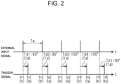
FIG. 2 is a view for explaining a relationship between external input signals and trigger signals. -
FIG. 3 is a schematic diagram showing information displayed on a display. - The following will describe an embodiment of a loom stroboscope with reference to
FIGS. 1 to 3 . The loom stroboscope is a stroboscope used for observation of a loom. In the present embodiment, the observation of the loom is to observe the travelling condition of a weft yarn. Aloom 100 of the present embodiment is an air jet loom that uses air to insert a weft yarn. - As illustrated in
FIG. 1 , theloom 100 includes amain shaft 101 and a nozzle (not illustrated) from which a weft yarn is injected. Themain shaft 101 is driven by a main motor (not illustrated). The timing at which the weft yarn is injected from the nozzle corresponds to a rotation angle of themain shaft 101. Specifically, the weft yarn is injected from the nozzle when themain shaft 101 rotates by a predetermined rotation angle from a particular rotation angle. In the following description, the particular rotation angle of themain shaft 101 is referred to as a reference angle. Furthermore, an angle delayed from the reference angle is referred to as a delay angle. - The
loom 100 includes a detectingunit 102 and anoutput unit 103. The detectingunit 102 is configured to detect the rotation angle of themain shaft 101. The detectingunit 102 is, for example, a rotary encoder. The detectingunit 102 is connected to theoutput unit 103. The detectingunit 102 transmits a detected rotation angle of themain shaft 101 to theoutput unit 103. Theoutput unit 103 transmits a signal to the loom stroboscope every time the detected rotation angle corresponds to a predetermined reference angle. For example, if the reference angle is 0°, theoutput unit 103 outputs a signal every time the rotation angle of themain shaft 101 becomes 0°. - A
loom stroboscope 10 includes alight emitting device 11, acamera 12, acontroller 13, aninput unit 14, and adisplay 15. - The
light emitting device 11 is, for example, an LED light. Thelight emitting device 11 is disposed on a surface of a housing (not illustrated) of theloom stroboscope 10. Thelight emitting device 11 is connected to atrigger control unit 13a of thecontroller 13. Thetrigger control unit 13a will be described later. Thelight emitting device 11 emits light upon receiving a trigger signal from thetrigger control unit 13a. - The
camera 12 is an imaging device. Thecamera 12 includes an image sensor. Thecamera 12 is disposed on the surface of the housing so that thecamera 12 captures images of an object illuminated by thelight emitting device 11. Thecamera 12 is connected to thetrigger control unit 13a. Thecamera 12 is configured to capture an image upon receiving a trigger signal from thetrigger control unit 13a. - The loom
stroboscope 10 is arranged so that thelight emitting device 11 illuminates the weft yarn and thecamera 12 captures images of the weft yarn in theloom 100. The loomstroboscope 10 may be fixed at a desired position with a fixing device (not illustrated). - The
controller 13 includes a processor and a storage unit. For example, the processor is a Central Processing Unit (CPU), a Graphics Processing Unit (GPU), or a Digital Signal Processor (DSP). The storage unit includes Random Access Memory (RAM) and Read Only Memory (ROM). The storage unit stores program code or instructions for causing the processor to execute the processing. The storage unit, i.e., a computer-readable medium, includes any available medium accessible by a general-purpose or dedicated computer. Thecontroller 13 may include a hardware circuit, such as an Application Specific Integrated Circuit (ASIC) or a Field Programmable Gate Array (FPGA). Thecontroller 13, which is a processing circuit, may include one or more processors operating in accordance with a computer program, one or more hardware circuits, such as ASICs and FPGAs, or combinations thereof. - The
controller 13 includes thetrigger control unit 13a for controlling a trigger signal and adisplay control unit 13b for controlling thedisplay 15. As previously described, the trigger signal of the present embodiment is a signal for causing thelight emitting device 11 to emit light and thecamera 12 to capture an image. In other words, thetrigger control unit 13a is configured to control the trigger signal to control thelight emitting device 11 and thecamera 12. - The
trigger control unit 13a is connected to theoutput unit 103 of theloom 100. Thetrigger control unit 13a receives a signal, which is an external input signal, from theoutput unit 103 of theloom 100. Thetrigger control unit 13a sets the delay angle. The setting of the delay angle will be described later. Thetrigger control unit 13a controls the trigger signal based on the external input signal from theloom 100 and the set delay angle. - As illustrated in
FIG. 2 , thetrigger control unit 13a determines a rotation period Tm of themain shaft 101 based on the interval between the external input signals. Thetrigger control unit 13a converts the delay angle to a delay time Td by using the rotation period Tm of themain shaft 101 and the reference angle. Thetrigger control unit 13a transmits the trigger signal to thelight emitting device 11 and thecamera 12 at a time ts, which is a time when a delay time Td has elapsed from a time tr at which the external input signal is input. In other words, thetrigger control unit 13a transmits the trigger signal to thelight emitting device 11 and thecamera 12 when themain shaft 101 rotates by the delay angle from the reference angle. - According to the present embodiment, the
loom stroboscope 10 has a first setting mode in which the loomstroboscope 10 sets the delay angle to a fixed value and a second setting mode in which the loomstroboscope 10 changes the delay angle. - When the
loom stroboscope 10 is in the first setting mode, thetrigger control unit 13a sets the delay angle to one angle, which is input by the observer via theinput unit 14. - When the
loom stroboscope 10 is in the second setting mode, thetrigger control unit 13a changes the delay angle by a predetermined amount of change within a predetermined range of change. That is, thetrigger control unit 13a sets multiple delay angles that are different by a predetermined amount of change within a predetermined range of change. - The
trigger control unit 13a of the present embodiment outputs a trigger signal once per rotation of themain shaft 101. Thetrigger control unit 13a sets one delay angle per rotation of themain shaft 101. Thetrigger control unit 13a changes the delay angle by the predetermined amount of change within the predetermined range of change per rotation of themain shaft 101. - In the present embodiment, the range of change and the amount of change of the delay angle are set by the observer. The range of change of the delay angle is set by setting the minimum value and the maximum value of the delay angle. That is, the range of change of the delay angle is defined by the minimum value and the maximum value.
- In the present embodiment, the
trigger control unit 13a repeatedly changes the delay angle by the predetermined amount of change within the predetermined range of change until the observer stops the second setting mode. Specifically, thetrigger control unit 13a changes the delay angle by the predetermined amount of change from the minimum value to the maximum value within the predetermined range of change. Thetrigger control unit 13a changes the delay angle to the maximum value of the range of change, and then resets the delay angle to the minimum value of the range of change. - The
input unit 14 is disposed on the housing of theloom stroboscope 10. Theinput unit 14 is a part of theloom stroboscope 10 operated by the observer to input information into theloom stroboscope 10. Theinput unit 14 of the present embodiment has, for example, a dial for inputting an angle and an operation button for selecting a button displayed on thedisplay 15. - The
display 15 is disposed on the housing of theloom stroboscope 10. Thedisplay 15 is controlled by thedisplay control unit 13b to display. - As illustrated in
FIG. 3 , thedisplay control unit 13b causes thedisplay 15 to display an operation screen and the captured image. Thedisplay 15 serves as an operation screen display for displaying an operation screen and also serves as an image display for displaying captured images. - The observer operates the
loom stroboscope 10 from the operation screen.FIG. 3 illustrates the operation screen when theloom stroboscope 10 is in the second setting mode. The operation screen is provided with an input screen for inputting the minimum value, the maximum value, and the amount of change of the delay angle; an OK button for starting the second setting mode; and a cancel button for stopping the second setting mode. Although not illustrated, the operation screen is also provided with a mode change button for changing the setting mode of theloom stroboscope 10 to the first setting mode; a start button for activating theloom stroboscope 10; and a stop button for stopping theloom stroboscope 10. - The observer inputs a desired delay angle by turning the dial of the
input unit 14 while checking the angle displayed on the input screen of thedisplay 15. The observer selects a desired button from the buttons displayed on thedisplay 15 by operating the operation button of theinput unit 14 while checking the operation screen of thedisplay 15. - The following will specifically describe the operation of the
loom stroboscope 10 in the second setting mode with a specific example. - The observer operates the
input unit 14 to set the range of change and the amount of change of the delay angle. For example, in a case that the weft yarn is injected from the nozzle when the rotation angle of the main shaft is 90°, the delay angle needs to be set to a value near 90° so that the condition of the weft yarn can be observed. Accordingly, the observer enters 90 for the minimum value [°], 105 for the maximum value [°], and 5 for the amount of change [°] on the input screen of the operation screen. Then, the observer selects the OK button. - The
trigger control unit 13a sets the delay angle based on the minimum value, the maximum value, and the amount of change that are input via theinput unit 14. Thetrigger control unit 13a changes the delay angle by 5° increments in the range of change of 90° to 105°. - As illustrated in
FIG. 2 , thetrigger control unit 13a sets the delay angle to 90°. Thetrigger control unit 13a outputs a trigger signal at a time ts1[s] after the lapse of a delay time Td1[s], which corresponds to the delay angle of 90°, from a time tr1[s] at which an external input signal is input. - Sequentially, the
trigger control unit 13a changes the delay angle to 95°. Thetrigger control unit 13a outputs a trigger signal at a time ts2[s] after the lapse of a delay time Td2[s], which corresponds to the delay angle of 95°, from a time tr2[s] at which an external input signal is input. - Then, the
trigger control unit 13a changes the delay angle to 100°. Thetrigger control unit 13a outputs a trigger signal at a time ts3[s] after the lapse of a delay time Td3[s], which corresponds to the delay angle of 100°, from a time tr3[s] at which an external input signal is input. - Then, the
trigger control unit 13a changes the delay angle to 105°. Thetrigger control unit 13a outputs a trigger signal at a time ts4[s] after the lapse of a delay time Td4[s], which corresponds to the delay angle of 105°, from a time tr4[s] at which an external input signal is input. - Then, the
trigger control unit 13a resets the delay angle to 90°. Thetrigger control unit 13a outputs a trigger signal at a time ts5[s] after the lapse of the delay time Td1[s], which corresponds to the delay angle of 90°, from a time tr5[s] at which an external input signal is input. - In such a way, the
trigger control unit 13a repeatedly changes the delay angle until the observer stops the second setting mode by selecting the cancel button. - The
light emitting device 11 emits light every time receiving the trigger signal. Thecamera 12 captures an image every time receiving the trigger signal. Thecamera 12 captures an image at the same time as thelight emitting device 11 emits light. That is, thecamera 12 captures an image in synchronization with the light emission of thelight emitting device 11. Thedisplay control unit 13b causes thedisplay 15 to display the image captured by thecamera 12. This allows the observer to observe the traveling condition of the weft yarn with the captured image displayed on thedisplay 15, in addition to eye observation of the weft yarn. - The following will describe operations and advantageous effects of the present embodiment.
- (1) The
trigger control unit 13a changes the delay angle by a predetermined amount of change within a predetermined range of change. This eliminates the need for the observer to input the delay angle every time to change the delay angle. This therefore improves efficiency in the adjustment of the delay angle. - (2) The loom
stroboscope 10 includes theinput unit 14 for inputting the predetermined range of change and the predetermined amount of change. This configuration allows the observer to operate theinput unit 14 to set the desired range of change and the desired amount of change of the delay angle. - (3) The loom
stroboscope 10 includes thecamera 12 that is configured to capture an image in synchronization with light emission of thelight emitting device 11. This configuration allows thecamera 12 to capture images that show the condition of theloom 100 at various delay angles. - (4) The loom
stroboscope 10 includes thedisplay 15 for displaying the images captured by thecamera 12. This allows the observer to observe the travelling condition of the weft yarn with thedisplay 15. - (5) The loom 100 operates at a high speed. Accordingly, the eye observation of the weft yarn may fail unless the
trigger control unit 13a repeatedly changes the delay angle. However, in the present embodiment, thetrigger control unit 13a repeatedly changes the delay angle, so that the eye observation is facilitated. - The embodiment of the present invention may be modified in various manners, as exemplified below. The present embodiment and the following modification examples may be combined within the scope of the present invention.
- ∘ The
loom stroboscope 10 does not necessarily need thecamera 12. - ∘ The
loom stroboscope 10 may have the second setting mode only. - ∘ The
loom stroboscope 10 may include a touch panel, instead of theinput unit 14 and thedisplay 15. The touch panel is disposed on the housing of theloom stroboscope 10. The touch panel serves as both the input unit and the display. In this configuration, the observer operates the touch panel to input a predetermined range of change and a predetermined amount of change. Thedisplay control unit 13b controls the touch panel to display. The observer uses the captured image displayed on the touch panel to observe the weft yarn. - ∘ The operation screen display for displaying the operation screen and the image display for displaying the captured images may be individually disposed on the housing of the
loom stroboscope 10. - ∘ In the
loom stroboscope 10, the range of change of the delay angle may be defined by only one of the minimum value and the maximum value set by the observer. When the observer sets only the minimum value of the delay angle, the maximum value of the delay angle needs to be stored in advance in the storage unit of thecontroller 13. When the observer sets only the maximum value of the delay angle, the minimum value of the delay angle needs to be stored in advance in the storage unit of thecontroller 13. - ∘ According to the present embodiment, the range of change of the delay angle is defined by the minimum value and the maximum value, but may be defined by a reference value θb and an allowable deviation ±α from the reference value θb. In this modification, the delay angle is changed in a range of change of (θb - α) to (θb + α).
- Alternatively, in the
loom stroboscope 10, only the reference value θb may be set by the observer. In this modification, the allowable deviation α is stored in the storage unit of thecontroller 13. - ∘ The amount of change of the delay angle may be a fixed value stored in advance in the storage unit of the
controller 13. - ∘ The
trigger control unit 13a does not necessarily need to repeatedly change the delay angle by the predetermined amount of change within the predetermined range of change. In other words, thetrigger control unit 13a may end the setting of the delay angle after changing the delay angle to the maximum value of the range of change. - ∘ The
loom stroboscope 10 may have a connection port to which an external memory, such as a USB or an SD card, is connected. This configuration allows the images captured by thecamera 12 to be stored in the external memory. - ∘ The
camera 12 needs to capture an image in synchronization with the light emission of thelight emitting device 11, but thetrigger control unit 13a does not necessarily need to transmit a trigger signal to thecamera 12. - ∘ The object of the observation is not limited to the weft yarn. For example, the object of the observation may be the
loom 100. -
- 10 Loom stroboscope
- 11 Light emitting device
- 12 Camera
- 13a Trigger control unit
- 14 Input unit
- 15 Display as image display
- 100 Loom
- 101 Main shaft
Claims (5)
- A loom stroboscope comprising:a light emitting device; anda trigger control unit configured to transmit a trigger signal to the light emitting device to cause the light emitting device to emit light when a main shaft of a loom rotates by a delay angle from a reference angle, characterized in thatthe trigger control unit is configured to change the delay angle by a predetermined amount of change within a predetermined range of change.
- The loom stroboscope according to claim 1, characterized in that the loom stroboscope includes an input unit for inputting the predetermined range of change and the predetermined amount of change.
- The loom stroboscope according to claim 1 or 2, characterized in that the loom stroboscope includes a camera that is configured to capture an image in synchronization with light emission of the light emitting device.
- The loom stroboscope according to claim 3, characterized in that the loom stroboscope includes an image display for displaying the image captured by the camera.
- The loom stroboscope according to any one of claims 1 to 4, characterized in that the trigger control unit is configured to repeatedly change the delay angle by the predetermined amount of change within the predetermined range of change.
Applications Claiming Priority (2)
| Application Number | Priority Date | Filing Date | Title |
|---|---|---|---|
| JP2022024672A JP7771810B2 (en) | 2022-02-21 | 2022-02-21 | Loom stroboscope |
| PCT/JP2023/001977 WO2023157572A1 (en) | 2022-02-21 | 2023-01-23 | Stroboscope for loom |
Publications (2)
| Publication Number | Publication Date |
|---|---|
| EP4486063A1 true EP4486063A1 (en) | 2025-01-01 |
| EP4486063A4 EP4486063A4 (en) | 2025-06-11 |
Family
ID=87578262
Family Applications (1)
| Application Number | Title | Priority Date | Filing Date |
|---|---|---|---|
| EP23756100.6A Pending EP4486063A4 (en) | 2022-02-21 | 2023-01-23 | STROBOSCOPE FOR WEAVING MACHINES |
Country Status (4)
| Country | Link |
|---|---|
| EP (1) | EP4486063A4 (en) |
| JP (1) | JP7771810B2 (en) |
| CN (1) | CN118592088A (en) |
| WO (1) | WO2023157572A1 (en) |
Families Citing this family (1)
| Publication number | Priority date | Publication date | Assignee | Title |
|---|---|---|---|---|
| CN119332396A (en) * | 2024-12-18 | 2025-01-21 | 苏州伟创电气科技股份有限公司 | A weft yarn detection method, device, equipment and storage medium |
Family Cites Families (4)
| Publication number | Priority date | Publication date | Assignee | Title |
|---|---|---|---|---|
| JPH069158B2 (en) * | 1985-11-11 | 1994-02-02 | シンポ工業株式会社 | Stroboscope control device |
| JP2773128B2 (en) * | 1988-03-11 | 1998-07-09 | 株式会社豊田自動織機製作所 | Stroboscope control device in loom |
| JPH02284386A (en) * | 1989-04-24 | 1990-11-21 | Shimpo Ind Co Ltd | Stroboscope controlling device |
| JP2777738B2 (en) * | 1990-02-13 | 1998-07-23 | 津田駒工業株式会社 | Apparatus for judging the quality of weft insertion-related members of an air jet loom |
-
2022
- 2022-02-21 JP JP2022024672A patent/JP7771810B2/en active Active
-
2023
- 2023-01-23 EP EP23756100.6A patent/EP4486063A4/en active Pending
- 2023-01-23 WO PCT/JP2023/001977 patent/WO2023157572A1/en not_active Ceased
- 2023-01-23 CN CN202380017736.7A patent/CN118592088A/en active Pending
Also Published As
| Publication number | Publication date |
|---|---|
| CN118592088A (en) | 2024-09-03 |
| EP4486063A4 (en) | 2025-06-11 |
| JP7771810B2 (en) | 2025-11-18 |
| WO2023157572A1 (en) | 2023-08-24 |
| JP2023121370A (en) | 2023-08-31 |
Similar Documents
| Publication | Publication Date | Title |
|---|---|---|
| US9581802B2 (en) | Endoscope device, and measurement method | |
| US20050288556A1 (en) | Electronic endoscope system for fluorescence observation | |
| EP2700347A1 (en) | Endoscope and image acquisition method | |
| US9232148B2 (en) | Image capture apparatus and zooming method | |
| CN101449958A (en) | Noise reduction system, endoscope processor, and endoscope system | |
| JP7771810B2 (en) | Loom stroboscope | |
| US20140300698A1 (en) | Endoscopic arrangement | |
| US9962068B2 (en) | Image pickup system and control method of image pickup system | |
| US20180324385A1 (en) | Storage device, control device, display device, and storage method | |
| JP6387713B2 (en) | Ultrasonic diagnostic apparatus and ultrasonic probe | |
| EP4485956A1 (en) | Stroboscope | |
| WO2023188915A1 (en) | Loom stroboscope, and observation system | |
| KR20160004536A (en) | Inspection device for fabric | |
| US11503990B2 (en) | Imaging system, processing device and illumination control method to set emission timing of illumination light in readout period of signal value of imager | |
| JP6492588B2 (en) | Projector and projector control method | |
| KR20160090275A (en) | Inspection device for fabric | |
| JP2017032496A (en) | Shaft vibration measuring device | |
| EP1602761A2 (en) | Setting device for loom | |
| US20110313254A1 (en) | Light source device and endoscopic apparatus | |
| US12495214B2 (en) | Pulse illumination imaging of a target element | |
| US12300162B2 (en) | Method of determining a state of a display | |
| JP2008045926A (en) | Optical displacement sensor and control method thereof | |
| CN111367322A (en) | Rotary display device, rotary display control method thereof and display curtain wall | |
| JP3388839B2 (en) | X-ray rotation stereoscopic imaging device | |
| JP2019039093A (en) | Device for adjusting stop mark in loom |
Legal Events
| Date | Code | Title | Description |
|---|---|---|---|
| STAA | Information on the status of an ep patent application or granted ep patent |
Free format text: STATUS: THE INTERNATIONAL PUBLICATION HAS BEEN MADE |
|
| PUAI | Public reference made under article 153(3) epc to a published international application that has entered the european phase |
Free format text: ORIGINAL CODE: 0009012 |
|
| STAA | Information on the status of an ep patent application or granted ep patent |
Free format text: STATUS: REQUEST FOR EXAMINATION WAS MADE |
|
| 17P | Request for examination filed |
Effective date: 20240606 |
|
| AK | Designated contracting states |
Kind code of ref document: A1 Designated state(s): AL AT BE BG CH CY CZ DE DK EE ES FI FR GB GR HR HU IE IS IT LI LT LU LV MC ME MK MT NL NO PL PT RO RS SE SI SK SM TR |
|
| REG | Reference to a national code |
Ref country code: DE Ref legal event code: R079 Free format text: PREVIOUS MAIN CLASS: H05B0041340000 Ipc: D03D0047300000 |
|
| DAV | Request for validation of the european patent (deleted) | ||
| DAX | Request for extension of the european patent (deleted) | ||
| A4 | Supplementary search report drawn up and despatched |
Effective date: 20250513 |
|
| RIC1 | Information provided on ipc code assigned before grant |
Ipc: G03B 39/00 20210101ALN20250507BHEP Ipc: G03B 15/05 20210101ALN20250507BHEP Ipc: H05B 47/105 20200101ALI20250507BHEP Ipc: D03J 1/00 20060101ALI20250507BHEP Ipc: D03D 47/30 20060101AFI20250507BHEP |
|
| GRAP | Despatch of communication of intention to grant a patent |
Free format text: ORIGINAL CODE: EPIDOSNIGR1 |
|
| STAA | Information on the status of an ep patent application or granted ep patent |
Free format text: STATUS: GRANT OF PATENT IS INTENDED |
|
| RIC1 | Information provided on ipc code assigned before grant |
Ipc: D03D 47/30 20060101AFI20260210BHEP Ipc: D03J 1/00 20060101ALI20260210BHEP Ipc: H05B 47/105 20200101ALI20260210BHEP Ipc: G03B 15/05 20210101ALN20260210BHEP Ipc: G03B 39/00 20210101ALN20260210BHEP |
|
| INTG | Intention to grant announced |
Effective date: 20260219 |